EP0465117B1 - Vegetation cutting tool - Google Patents
Vegetation cutting tool Download PDFInfo
- Publication number
- EP0465117B1 EP0465117B1 EP91305807A EP91305807A EP0465117B1 EP 0465117 B1 EP0465117 B1 EP 0465117B1 EP 91305807 A EP91305807 A EP 91305807A EP 91305807 A EP91305807 A EP 91305807A EP 0465117 B1 EP0465117 B1 EP 0465117B1
- Authority
- EP
- European Patent Office
- Prior art keywords
- teeth
- blade
- cutting
- faces
- sides
- Prior art date
- Legal status (The legal status is an assumption and is not a legal conclusion. Google has not performed a legal analysis and makes no representation as to the accuracy of the status listed.)
- Expired - Lifetime
Links
- 238000005520 cutting process Methods 0.000 title claims description 54
- 230000036346 tooth eruption Effects 0.000 claims description 22
- 238000000034 method Methods 0.000 claims description 13
- 230000008569 process Effects 0.000 claims description 13
- 238000009966 trimming Methods 0.000 claims description 9
- 239000002184 metal Substances 0.000 claims description 8
- 230000009471 action Effects 0.000 claims description 5
- 239000011521 glass Substances 0.000 claims description 5
- 239000007769 metal material Substances 0.000 claims description 2
- 238000010008 shearing Methods 0.000 claims description 2
- 238000004519 manufacturing process Methods 0.000 description 9
- 230000008901 benefit Effects 0.000 description 6
- 239000000463 material Substances 0.000 description 4
- 230000001154 acute effect Effects 0.000 description 2
- 230000015572 biosynthetic process Effects 0.000 description 2
- 230000008878 coupling Effects 0.000 description 2
- 238000010168 coupling process Methods 0.000 description 2
- 238000005859 coupling reaction Methods 0.000 description 2
- 238000003754 machining Methods 0.000 description 2
- 230000004048 modification Effects 0.000 description 1
- 238000012986 modification Methods 0.000 description 1
- 239000002002 slurry Substances 0.000 description 1
- 238000010408 sweeping Methods 0.000 description 1
Images


Classifications
-
- B—PERFORMING OPERATIONS; TRANSPORTING
- B21—MECHANICAL METAL-WORKING WITHOUT ESSENTIALLY REMOVING MATERIAL; PUNCHING METAL
- B21D—WORKING OR PROCESSING OF SHEET METAL OR METAL TUBES, RODS OR PROFILES WITHOUT ESSENTIALLY REMOVING MATERIAL; PUNCHING METAL
- B21D53/00—Making other particular articles
- B21D53/60—Making other particular articles cutlery wares; garden tools or the like
- B21D53/64—Making other particular articles cutlery wares; garden tools or the like knives; scissors; cutting blades
-
- A—HUMAN NECESSITIES
- A01—AGRICULTURE; FORESTRY; ANIMAL HUSBANDRY; HUNTING; TRAPPING; FISHING
- A01G—HORTICULTURE; CULTIVATION OF VEGETABLES, FLOWERS, RICE, FRUIT, VINES, HOPS OR SEAWEED; FORESTRY; WATERING
- A01G3/00—Cutting implements specially adapted for horticultural purposes; Delimbing standing trees
- A01G3/04—Apparatus for trimming hedges, e.g. hedge shears
- A01G3/047—Apparatus for trimming hedges, e.g. hedge shears portable
- A01G3/053—Apparatus for trimming hedges, e.g. hedge shears portable motor-driven
-
- B—PERFORMING OPERATIONS; TRANSPORTING
- B23—MACHINE TOOLS; METAL-WORKING NOT OTHERWISE PROVIDED FOR
- B23D—PLANING; SLOTTING; SHEARING; BROACHING; SAWING; FILING; SCRAPING; LIKE OPERATIONS FOR WORKING METAL BY REMOVING MATERIAL, NOT OTHERWISE PROVIDED FOR
- B23D63/00—Dressing the tools of sawing machines or sawing devices for use in cutting any kind of material, e.g. in the manufacture of sawing tools
- B23D63/06—Upsetting the cutting edges of saw teeth, e.g. swaging
-
- B—PERFORMING OPERATIONS; TRANSPORTING
- B23—MACHINE TOOLS; METAL-WORKING NOT OTHERWISE PROVIDED FOR
- B23D—PLANING; SLOTTING; SHEARING; BROACHING; SAWING; FILING; SCRAPING; LIKE OPERATIONS FOR WORKING METAL BY REMOVING MATERIAL, NOT OTHERWISE PROVIDED FOR
- B23D63/00—Dressing the tools of sawing machines or sawing devices for use in cutting any kind of material, e.g. in the manufacture of sawing tools
- B23D63/18—Straightening damaged saw blades; Reconditioning the side surface of saw blades, e.g. by grinding
-
- B—PERFORMING OPERATIONS; TRANSPORTING
- B23—MACHINE TOOLS; METAL-WORKING NOT OTHERWISE PROVIDED FOR
- B23D—PLANING; SLOTTING; SHEARING; BROACHING; SAWING; FILING; SCRAPING; LIKE OPERATIONS FOR WORKING METAL BY REMOVING MATERIAL, NOT OTHERWISE PROVIDED FOR
- B23D65/00—Making tools for sawing machines or sawing devices for use in cutting any kind of material
- B23D65/02—Making saw teeth by punching, cutting, or planing
Definitions
- This invention relates to vegetation cutting tools having reciprocating teeth, such as used for trimming hedges.
- Hedge trimming tools are required to cut vegetation ranging from small limbs of for example 0.95 cm. (3/8 inch) diameter, down to the size of leaf stems.
- a vegetation cutting tool of the kind comprising two substantially planar blades each having a blade body and laterally projected teeth, the blades lying in face to face relation, and means for reciprocating the blades relative to each other whereby the teeth of the blades cooperatively open and close in a shearing operation, one of the blades being a cutting blade having an outer surface opposed to an inner surface (hereafter referred to as first and second surfaces) adjacent the other blade, the teeth of the cutting blade being cutting teeth having teeth faces parallel to and adjacent the second surface and further having sides inclined to the teeth faces to form concave cutting edges at the intersection with said teeth faces.
- a tool of this kind is directed into or along the hedge and as vegetation enters the space between the fixed blade teeth, it is severed by the reciprocating teeth.
- teeth of the overlying cutting blade are a primary consideration in the manufacture of tools of this kind.
- the teeth were produced in what can essentially be considered as a two-step operation.
- holes or openings were made, e.g. by a circular punch driven through the blade thickness at the leading edge of the blade.
- the holes are formed so as to overlap the leading edge, resulting in a scalloped configuration having hour glass configured teeth separated by C-shaped openings.
- a frusto conical sharpening tool rotated on its axis, is projected down into the C-shaped openings to bevel or flare outwardly the blade thickness from the bottom surface to the top surface of the blade.
- the blade is laid with the bottom surface flat on the fixed blade so that the cutting edges slide over the fixed blade fingers in a scissors-like slicing action.
- the invention accordingly provides a process of forming a cutting blade for a vegetation cutting tool, the process comprising the steps of forming open-sided openings in an edge of a planar metal strip having first and second opposed surfaces, the metal material between the openings forming unfinished cutting teeth, upsetting the sides of the unfinished cutting teeth downwardly from said first surface whereby the sides are projected angularly and downwardly below the plane of the second surface of the blade, and grinding coplanar faces through the teeth sides projected below the said second surface of the blade to form cutting edges for the cutting teeth.
- the invention also provides a vegetation cutting tool of the kind described in which said teeth faces are coplanar and spaced from the second surface of the cutting blade towards the other blade, so as to space the cutting blade second surface from the opposed surface of the other blade.
- the present invention thus does away with the conventional practice of forming the cutting edges with a rotating frusto conical sharpening tool.
- the same first step is performed to create the hour glass configured teeth separated by C-shaped openings in the leading edges of the blade.
- the teeth (which are unfinished in this stage of operation) are then curled or curved downwardly on both side edges.
- This curling operation results in the top surface of the teeth being projected through the plane defined by the bottom surface of the blade.
- a machining tool is directed along the bottom surface of the blade and in a single machining operation grinds faces through the thickness of the downwardly projected sides of the teeth. The faces form acute angles with the top surfaces of the blade which become the cutting edges.
- the invention will thus be seen to provide a cutting blade of a vegetation trimming tool having teeth configured for effective cutting and a process for easy manufacture of such a blade.
- Fig. 1 shows a hedge trimming tool 10 arranged to be mounted to a power head (not shown).
- a bottom blade 12 of the tool 10 is fixedly mounted to the power head.
- a cutting blade 14 overlies the fixed blade 12 and is coupled to an output shaft of the power head as represented by a coupling arm 16.
- a flat holding bar 18 is secured to the fixed blade 12 by rivets 20.
- Slots 22 in the cutting blade 14 allow the cutting blade to reciprocate relative to the fixed blade 12 and the holding bar 18, as indicated by arrows 24. Reciprocation of cutting blade 14 is effected by the output shaft of the power head coupled to the cutting blade 14 by coupling arm 16.
- the hedge trimming tool 10 is operated to direct the tool in a sweeping action in either of the directions indicated by arrows 26 and 28.
- the tool can be constructed to function in one or the other of the directions 26,28, but the tool is typically designed to function in both directions as illustrated for convenience and versatility.
- the leading edge of the tool or its components i.e. the leading edge of the fixed blade 12 or the reciprocating blade 14, it will be understood that the term has reference to the direction of operation and includes one or both leading edges as determined by the arrows 26,28.
- the fixed bottom blade 12 is scalloped along its leading edge to produce forwardly directed fingers or teeth 30. These teeth are spaced apart a distance to receive therebetween the maximum thickness of branches of a hedge to be trimmed, for example, 0.95 cm. (3/8 inch).
- the reciprocating blade 14 is scalloped along its leading edge in a manner to produce cutting teeth 32, which are described in detail hereafter. These teeth 32 reciprocate between a retracted position in which the teeth overlying the teeth 30 (shown in solid lines), and a closed position with the teeth 32 (designated 32') positioned between the teeth 30 (illustrated in dash lines at the upper right end of Fig. 1). It will be understood that material such as branches (less than 0.95 cm.
- the teeth 32 of the cutting blade 14 are formed of complex curves which can best be seen from the perspective view of Fig. 4.
- the teeth 32 of the blade 14 as shown in Fig. 1 at the upper left end have cutting edges 44 that generate a top view profile of the teeth that is relatively wide at the inner end 66 and outer tip 33 and relatively narrow across the middle to produce the hour glass shape.
- the teeth viewed from the end as indicated by view line 36 take on the shape of an inverted U. This is because the sides of the cutting teeth are curved downwardly.
- the operation that forms this U-shaped curve is illustrated in Fig. 6c.
- the teeth are bowed, i.e. the teeth sides are curved downwardly, so that the full blade thickness is projected angularly downwardly through the plane defined by the bottom surface 38 of the blade (See Fig. 6c at 48e).
- the advantages of the invention are primarily advantages in the production of the blade, but structural advantages are achieved as well.
- the faces 42 are slightly below bottom surface 38 of the blade. These faces 42 are the only surfaces contacting and sliding on the top surface of fixed blade 12. The total contact surface is thereby a fraction of the contact surface which would occur if the full bottom surface of the cutting blade were to ride on the fixed blade 12 (as in prior art hedge trimming tools) and the frictional resistance to the reciprocating action of the blade 14 is significantly reduced.
- a further advantage afforded by this tooth configuration is that the cutting edge 44 can be readily resharpened.
- the cutting edge 44 is shown rounded as when worn.
- a resharpening medium applied against the faces 42 will result in the partial removal of the faces 42 as indicated by dash lines 46 to generate a resharpened cutting edge at the location of the reduced faces 42 as indicated at 44′.
- This sharpening medium can be a tool applied against the blade bottom following disassembly of the blade from the fixed blade, or it can be an aggregate strip or even a slurry of aggregate that is inserted between the blades. The tool is operated to reciprocate the blades for automatic or self sharpening.
- the primary benefit of the tooth configuration of the invention is in the simplified production of the blade.
- the steps of production are illustrated in Figs. 5-7.
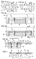
- Figs. 5a and 5b schematically illustrate the traditional first step wherein a die punch 46 having circular die cutters 47 punches circular holes 48 along both side edges 52 of a metal strip 50.
- the metal strip has been previously cut to size, e.g., 0.18 x 4.29 x 61 cm. (0.07 x 1.69 x 24.00 inches) from a roll of metal sheet material, e.g. 61 cm. (24 inches) wide and 0.18 cm. (0.07 inches) thick and some metres long.
- the die punch 46 overlaps the edges 52 as indicated by the dash lines 54 in Fig. 5a to form an open sided C-shaped opening 48.
- the next step is the step of upsetting, curving or curling the metal at the sides of the teeth, illustrated in Figs. 6a-6c.
- Fig. 6c is a cross section as will be apparent from noting the view lines of Figs. 6b and 6a.
- anvils 56 are positioned under the metal strip 58 between the holes 48.
- a forming tool 60 includes configured plungers 62. The plungers 62 are forced down through the openings 48 as illustrated in Fig. 6c to curl or curve the side edges of opening 48 around the anvil 56. It is important to note that this forming step results in the hole edge 48e being forced below the planar bottom surface 38 of the body 50.
- Fig. 7 illustrates the sharpening step which converts the strip 50 to the blade 14 and produces the configured cutting teeth 32.
- a sharpening tool 64 is simply directed along the bottom of the blade in a direction 39, parallel to and spaced slightly below the bottom surface 38 as illustrated.
- the rotating cylindrical sharpening tool 64 of Fig. 7 is merely a schematic illustration of such tools in general. (In actual practice, the blade is passed over the top of the blade bottom 38 to sharpen the teeth.) The movement of the sharpening tool 64 across the blade bottom projects through the teeth sides resulting in the formation of faces 42 and hence cutting edges 44. This final step of course converts the intermediate strip segments or portions 58 into the cutting teeth 32.
- each of the rivets 20 is provided with an enlarged diameter center section 64 that spaces the bar 18 from blade 12 to provide free sliding of the cutting blade 14.
- the faces 42 of the teeth 32 ridge on the top surface of the fixed blade teeth 30.
- the innermost portion of the edge 44 is curved inwardly (as indicated at 66 in Fig. 1) to a greater extent than tip 33 at the outer end of the teeth.
- the inner curve at 66 functions as a guide or cam surface to maintain the cutting teeth at a level above the top surface of the fingers and ensures that the teeth 32 will not project into the spacing between the teeth 30 so as to catch on these teeth.
Landscapes
- Engineering & Computer Science (AREA)
- Mechanical Engineering (AREA)
- Life Sciences & Earth Sciences (AREA)
- Biodiversity & Conservation Biology (AREA)
- Ecology (AREA)
- Forests & Forestry (AREA)
- Environmental Sciences (AREA)
- Harvester Elements (AREA)
Description
- This invention relates to vegetation cutting tools having reciprocating teeth, such as used for trimming hedges.
- Hedge trimming tools are required to cut vegetation ranging from small limbs of for example 0.95 cm. (3/8 inch) diameter, down to the size of leaf stems. There is known from US-A-2 558 459 a vegetation cutting tool of the kind comprising two substantially planar blades each having a blade body and laterally projected teeth, the blades lying in face to face relation, and means for reciprocating the blades relative to each other whereby the teeth of the blades cooperatively open and close in a shearing operation, one of the blades being a cutting blade having an outer surface opposed to an inner surface (hereafter referred to as first and second surfaces) adjacent the other blade, the teeth of the cutting blade being cutting teeth having teeth faces parallel to and adjacent the second surface and further having sides inclined to the teeth faces to form concave cutting edges at the intersection with said teeth faces. A tool of this kind is directed into or along the hedge and as vegetation enters the space between the fixed blade teeth, it is severed by the reciprocating teeth.
- Effective formation of the teeth of the overlying cutting blade is a primary consideration in the manufacture of tools of this kind. Heretofore the teeth were produced in what can essentially be considered as a two-step operation. First, holes or openings were made, e.g. by a circular punch driven through the blade thickness at the leading edge of the blade. The holes are formed so as to overlap the leading edge, resulting in a scalloped configuration having hour glass configured teeth separated by C-shaped openings.
- In the second step of the prior manufacturing process, a frusto conical sharpening tool, rotated on its axis, is projected down into the C-shaped openings to bevel or flare outwardly the blade thickness from the bottom surface to the top surface of the blade. This creates cutting edges along the concave curved sides of the hour glass configured teeth at the bottom surface of the blade. The blade is laid with the bottom surface flat on the fixed blade so that the cutting edges slide over the fixed blade fingers in a scissors-like slicing action.
- Of concern in this manner of forming the teeth is the substantial cost of forming the cutting edges, i.e. the step of projecting a rotating frusto conical sharpening tool into the C-shaped openings to bevel the blade thickness and thereby form the cutting edges.
- The invention accordingly provides a process of forming a cutting blade for a vegetation cutting tool, the process comprising the steps of forming open-sided openings in an edge of a planar metal strip having first and second opposed surfaces, the metal material between the openings forming unfinished cutting teeth, upsetting the sides of the unfinished cutting teeth downwardly from said first surface whereby the sides are projected angularly and downwardly below the plane of the second surface of the blade, and grinding coplanar faces through the teeth sides projected below the said second surface of the blade to form cutting edges for the cutting teeth.
- The invention also provides a vegetation cutting tool of the kind described in which said teeth faces are coplanar and spaced from the second surface of the cutting blade towards the other blade, so as to space the cutting blade second surface from the opposed surface of the other blade.
- The present invention thus does away with the conventional practice of forming the cutting edges with a rotating frusto conical sharpening tool. In the preferred embodiment, the same first step is performed to create the hour glass configured teeth separated by C-shaped openings in the leading edges of the blade. The teeth (which are unfinished in this stage of operation) are then curled or curved downwardly on both side edges. This curling operation results in the top surface of the teeth being projected through the plane defined by the bottom surface of the blade. A machining tool is directed along the bottom surface of the blade and in a single machining operation grinds faces through the thickness of the downwardly projected sides of the teeth. The faces form acute angles with the top surfaces of the blade which become the cutting edges.
- Whereas in the present invention, two operations are required to produce the desired cutting edges, these operations are accomplished in only a fraction of the time previously required by the sharpening process with the frusto conical sharpening tool. Furthermore, it is desirable to offset the forces of the cutting edges below the bottom surface of the blade and the present invention allows for this, to reduce the surface-to-surface contact between the blades, which in turn reduces friction. Also, the tooth configuration of the present invention offers the potential of easy resharpening.
- The invention will thus be seen to provide a cutting blade of a vegetation trimming tool having teeth configured for effective cutting and a process for easy manufacture of such a blade.
- The present invention is further described below, by way of example, with reference to the accompanying drawings, in which:
- Fig. 1 is a top view of a hedge trimming tool in accordance with the present invention;
- Fig. 2 is an enlarged sectional view taken on view line 2-2 of Fig. 1;
- Fig. 3 is a partial side view taken on view line 3-3 of Fig. 2;
- Fig. 4 is a perspective view on a larger scale of a part of the cutting blade of the tool illustrated in Figs. 1-4;
- Figs. 4a and 4b illustrate the manner of forming the complexly curved cutting edge illustrated perspectively in Fig. 4;
- Figs. 5a and 5b illustrate a hole forming step used in producing the cutting blade of Fig. 4;
- Figs. 6a, 6b and 6c illustrate an edge curling step used in producing the cutting blade of Fig. 4; and
- Fig. 7 illustrates the edge sharpening step used in producing the cutting blade of Fig. 4.
- Referring first to Figs. 1-3, Fig. 1 shows a
hedge trimming tool 10 arranged to be mounted to a power head (not shown). Abottom blade 12 of thetool 10 is fixedly mounted to the power head. Acutting blade 14 overlies thefixed blade 12 and is coupled to an output shaft of the power head as represented by acoupling arm 16. Aflat holding bar 18 is secured to thefixed blade 12 byrivets 20.Slots 22 in thecutting blade 14 allow the cutting blade to reciprocate relative to thefixed blade 12 and theholding bar 18, as indicated byarrows 24. Reciprocation ofcutting blade 14 is effected by the output shaft of the power head coupled to thecutting blade 14 bycoupling arm 16. - The
hedge trimming tool 10 is operated to direct the tool in a sweeping action in either of the directions indicated byarrows directions fixed blade 12 or thereciprocating blade 14, it will be understood that the term has reference to the direction of operation and includes one or both leading edges as determined by thearrows - As can be seen in Fig. 1, the fixed
bottom blade 12 is scalloped along its leading edge to produce forwardly directed fingers orteeth 30. These teeth are spaced apart a distance to receive therebetween the maximum thickness of branches of a hedge to be trimmed, for example, 0.95 cm. (3/8 inch). Thereciprocating blade 14 is scalloped along its leading edge in a manner to producecutting teeth 32, which are described in detail hereafter. Theseteeth 32 reciprocate between a retracted position in which the teeth overlying the teeth 30 (shown in solid lines), and a closed position with the teeth 32 (designated 32') positioned between the teeth 30 (illustrated in dash lines at the upper right end of Fig. 1). It will be understood that material such as branches (less than 0.95 cm. diameter), twigs, leaves and the like slide into the spaces betweenteeth 30 and then into the opening between thecutting teeth 32, (with the cutting teeth reciprocated to the retracted position). Theteeth 32 close across the opening (position 32') with thetips 33 of the cutting teeth first hooking and drawing the materials into the opening. Continued movement of theteeth 32 across the opening, in co-operation with the opposedstationary teeth 30, slices through and severs the material. Several cycles of reciprocation may be required to sever the larger branches. However, the reciprocation is very rapid and the operator "feel" is uninterrupted. - All of the above description is as applicable to prior hedge trimming tools as it is to the illustrated tool of the present invention. The improvements provided by this invention are to be seen primarily in the production of the teeth of the reciprocating cutting blade, and to a lesser degree, in the operational benefit resulting from reduced friction.
- The
teeth 32 of thecutting blade 14 are formed of complex curves which can best be seen from the perspective view of Fig. 4. Consider first the shape of the teeth when viewed from the top as indicated byview line 34 in Fig. 4 and as seen in the plan view of Fig. 1. Theteeth 32 of theblade 14 as shown in Fig. 1 at the upper left end havecutting edges 44 that generate a top view profile of the teeth that is relatively wide at theinner end 66 andouter tip 33 and relatively narrow across the middle to produce the hour glass shape. - Referring now to Figs. 4 and 4a, the teeth viewed from the end as indicated by
view line 36, take on the shape of an inverted U. This is because the sides of the cutting teeth are curved downwardly. The operation that forms this U-shaped curve is illustrated in Fig. 6c. The teeth are bowed, i.e. the teeth sides are curved downwardly, so that the full blade thickness is projected angularly downwardly through the plane defined by thebottom surface 38 of the blade (See Fig. 6c at 48e). - With reference to Figs. 4a and 7, because the
top surfaces 40 of the teeth segments are projected at an angle to the planar body of the blade, the depending sides of the teeth can be ground off parallel to the bottom surface 38 (arrow 39 of Fig. 7) to form bottom teeth faces 42. The included acute angle α between faces 42 andtop surface 40 in Fig. 4a produces thecutting edge 44. - The advantages of the invention are primarily advantages in the production of the blade, but structural advantages are achieved as well. Note that the
faces 42 are slightly belowbottom surface 38 of the blade. These faces 42 are the only surfaces contacting and sliding on the top surface of fixedblade 12. The total contact surface is thereby a fraction of the contact surface which would occur if the full bottom surface of the cutting blade were to ride on the fixed blade 12 (as in prior art hedge trimming tools) and the frictional resistance to the reciprocating action of theblade 14 is significantly reduced. - A further advantage afforded by this tooth configuration is that the
cutting edge 44 can be readily resharpened. In Fig. 4b, thecutting edge 44 is shown rounded as when worn. A resharpening medium applied against thefaces 42 will result in the partial removal of thefaces 42 as indicated bydash lines 46 to generate a resharpened cutting edge at the location of the reduced faces 42 as indicated at 44′. This sharpening medium can be a tool applied against the blade bottom following disassembly of the blade from the fixed blade, or it can be an aggregate strip or even a slurry of aggregate that is inserted between the blades. The tool is operated to reciprocate the blades for automatic or self sharpening. - As previously indicated, the primary benefit of the tooth configuration of the invention is in the simplified production of the blade. The steps of production are illustrated in Figs. 5-7.
- Figs. 5a and 5b schematically illustrate the traditional first step wherein a
die punch 46 having circular diecutters 47 punchescircular holes 48 along both side edges 52 of ametal strip 50. (The metal strip has been previously cut to size, e.g., 0.18 x 4.29 x 61 cm. (0.07 x 1.69 x 24.00 inches) from a roll of metal sheet material, e.g. 61 cm. (24 inches) wide and 0.18 cm. (0.07 inches) thick and some metres long.) Thedie punch 46 overlaps theedges 52 as indicated by the dash lines 54 in Fig. 5a to form an open sided C-shapedopening 48. (As explained previously, in prior production processes, it is at this point that a frusto conical sharpening tool would be forced down through each hole or opening 48 to bevel the thickness of the strip upwardly and outwardly to form the sharpened edge co-planar to thebottom surface 38 of the strips.) - The next step, which is a deviation from the prior processes and is peculiar to this invention, is the step of upsetting, curving or curling the metal at the sides of the teeth, illustrated in Figs. 6a-6c. Fig. 6c is a cross section as will be apparent from noting the view lines of Figs. 6b and 6a. As will be most apparent from Fig. 6c,
anvils 56 are positioned under themetal strip 58 between theholes 48. A formingtool 60 includes configuredplungers 62. Theplungers 62 are forced down through theopenings 48 as illustrated in Fig. 6c to curl or curve the side edges of opening 48 around theanvil 56. It is important to note that this forming step results in thehole edge 48e being forced below theplanar bottom surface 38 of thebody 50. - Fig. 7 illustrates the sharpening step which converts the
strip 50 to theblade 14 and produces the configured cuttingteeth 32. A sharpeningtool 64 is simply directed along the bottom of the blade in adirection 39, parallel to and spaced slightly below thebottom surface 38 as illustrated. Those skilled in the art will be aware of the many different forms thattool 64 can take and the rotating cylindrical sharpeningtool 64 of Fig. 7 is merely a schematic illustration of such tools in general. (In actual practice, the blade is passed over the top of the blade bottom 38 to sharpen the teeth.) The movement of the sharpeningtool 64 across the blade bottom projects through the teeth sides resulting in the formation offaces 42 and hence cuttingedges 44. This final step of course converts the intermediate strip segments orportions 58 into the cuttingteeth 32. - The
bar 18, thecutting blade 14 and the fixedbar 12 are then assembled into the tool of Figs. 1-3. As shown in Fig. 2, each of therivets 20 is provided with an enlargeddiameter center section 64 that spaces thebar 18 fromblade 12 to provide free sliding of thecutting blade 14. The faces 42 of theteeth 32 ridge on the top surface of the fixedblade teeth 30. The innermost portion of theedge 44 is curved inwardly (as indicated at 66 in Fig. 1) to a greater extent thantip 33 at the outer end of the teeth. The inner curve at 66 functions as a guide or cam surface to maintain the cutting teeth at a level above the top surface of the fingers and ensures that theteeth 32 will not project into the spacing between theteeth 30 so as to catch on these teeth. - As seen in Fig. 1, sliding of the
reciprocating blade 14 is permitted by theslots 22 which extend parallel to the direction of reciprocating action indicated byarrow 24. It will be appreciated, however, that relationship of the twoblades cutting blade 14 is fixed to the power head andblade 12 is reciprocated. Yet again, both blades can be reciprocated so as to move in opposite directions. - Those skilled in the art will conceive variations and modifications of the tool and production method described without departing from the scope of the invention as defined in the claims appended hereto.
Claims (9)
- A process of forming a cutting blade (14) for a vegetation cutting tool, the process comprising the steps of:
forming open-sided openings (48) in an edge of a planar metal strip having first and second opposed surfaces, the metal material between the openings forming unfinished cutting teeth (32),
upsetting the sides of the unfinished cutting teeth downwardly from said first surface whereby the sides are projected angularly and downwardly below the plane of the second surface (38) of the blade, and
grinding coplanar faces (42) through the teeth sides projected below the said second surface of the blade to form cutting edges (44) for the cutting teeth. - A process as claimed in claim 1 wherein the faces are ground so as to be parallel to and spaced below the second surface of the blade.
- A process as claimed in claim 1 or 2 wherein the faces (42) are formed by the pass of a sharpening tool (64) directed along a plane parallel to the second surface (38) of the blade.
- A process as claimed in claim 1, 2 or 3 wherein the cutting teeth (32) have concavely curved sides (40) curved in the plane of the metal strip to thereby form a planar profile of an hour glass configuration.
- A process as claimed in claim 1, 2, 3 or 4 wherein the open-sided openings (48) are formed in a die stamping operation and the sides of the cutting teeth (32) are downwardly curved by positioning a forming anvil (56) at the bottom of the unfinished teeth and forcing down through the openings a plunger (62) configured to curve the teeth sides around the forming anvil.
- A process as claimed in any preceding claim wherein the cutting teeth (32) are formed by circular dies (47) that form C-shaped openings, by plungers (62) that curl the side edges of the C-shaped opening downwardly, and by a sharpening tool (64) which is passed parallel to the plane of the blade adjacent the second surface and through the depending sides to form the teeth faces (42).
- A vegetation cutting tool comprising:
two substantially planar blades (12,14) each having a blade body and laterally projected teeth (30,32), the blades lying in face to face relation, and means for reciprocating the blades relative to each other whereby the teeth of the blades cooperatively open and close in a shearing operation,
one of the blades being a cutting blade (14) having a first surface opposed to a second surface (38) adjacent the other blade (12), the teeth (32) of the cutting blade being cutting teeth (32) having teeth faces (42) parallel to and adjacent the second surface (38) and further having sides inclined to the teeth faces (42) to form concave cutting edges (44) at the intersection with said teeth faces (42) characterised in that said teeth faces (42) are coplanar and spaced from the second surface (38) of the cutting blade (14) towards the other blade (12), so as to space the cutting blade second surface from the opposed surface of the other blade. - A trimming tool as claimed in claim 7 wherein the cutting teeth (30,32) are configured as a complex curve with the sides curved in the plane of the blade to form an hour glass-like planar profile.
- A process of resharpening the cutting teeth of a tool as claimed in claim 7 or 8 comprising introducing a sharpening medium between the relatively reciprocating blades (12,14), whereby the cutting teeth (30,32) are sharpened by the relative reciprocating action of the blades.
Applications Claiming Priority (2)
| Application Number | Priority Date | Filing Date | Title |
|---|---|---|---|
| US546428 | 1990-06-29 | ||
| US07/546,428 US5093999A (en) | 1990-06-29 | 1990-06-29 | Vegetation cutting tool and method of manufacture |
Publications (2)
| Publication Number | Publication Date |
|---|---|
| EP0465117A1 EP0465117A1 (en) | 1992-01-08 |
| EP0465117B1 true EP0465117B1 (en) | 1994-09-21 |
Family
ID=24180385
Family Applications (1)
| Application Number | Title | Priority Date | Filing Date |
|---|---|---|---|
| EP91305807A Expired - Lifetime EP0465117B1 (en) | 1990-06-29 | 1991-06-27 | Vegetation cutting tool |
Country Status (5)
| Country | Link |
|---|---|
| US (1) | US5093999A (en) |
| EP (1) | EP0465117B1 (en) |
| JP (1) | JPH04229108A (en) |
| CA (1) | CA2041959A1 (en) |
| DE (1) | DE69104145T2 (en) |
Families Citing this family (17)
| Publication number | Priority date | Publication date | Assignee | Title |
|---|---|---|---|---|
| DE4134878A1 (en) * | 1991-10-23 | 1993-04-29 | Deere & Co | METHOD FOR PRODUCING A SUSPENDING SUSPENSION STRIP FOR A CHOPPING DEVICE, SEPARATION BAR AND CHOPPING DEVICE |
| IT1267685B1 (en) * | 1994-02-11 | 1997-02-07 | Valex Spa | HEDGE CUTTER BLADE |
| US5581891A (en) * | 1994-08-12 | 1996-12-10 | Black & Decker Inc. | Hedge trimmer with combination shearing and sawing blade assembly |
| EP0700632B1 (en) * | 1994-09-08 | 2000-03-15 | Nikkari Co., Ltd. | A cutting section for a cutting machine such as a mower or hedge trimmer |
| IT1287323B1 (en) * | 1996-07-26 | 1998-08-04 | Valex S R L Ora Valex S P A | Hedge trimmer blade assembly. |
| US8590355B2 (en) * | 2004-04-19 | 2013-11-26 | Rasspe Systemtechnik Gmbh & Co. Kg | Chopping blade and counterblade for a chopping device and process for its production |
| US20060096424A1 (en) * | 2004-11-05 | 2006-05-11 | Charles Klyzek | Cutting blade edge application method and apparatus |
| FR2907362B1 (en) * | 2006-10-18 | 2009-06-26 | Adiamas Soc Par Actions Simpli | METHOD OF MAKING A CRANTED TOOTH ON A CUTTING BLADE, INSTALLATION FOR CARRYING OUT SAID METHOD, AND KNIFE OBTAINED BY THIS PROCESS |
| FR2939008B1 (en) * | 2008-12-01 | 2011-06-24 | Pellenc Sa | MOTORIZED SIZE SELF-DECOATING APPARATUS, IN PARTICULAR HEDGE TRIMMER |
| DE102009008819A1 (en) * | 2009-02-13 | 2010-08-19 | Andreas Stihl Ag & Co. Kg | Knife arrangement of a hedge trimmer |
| US8826546B2 (en) | 2009-09-01 | 2014-09-09 | Husqvarna Ab | Cutting assembly for hand-held power tool |
| CN102057839A (en) * | 2010-10-26 | 2011-05-18 | 王书翰 | Tool for shearing branches and leaves |
| JP5874129B2 (en) * | 2011-12-20 | 2016-03-02 | 株式会社やまびこ | Reciprocating sliding blade structure |
| US20140115901A1 (en) * | 2012-10-26 | 2014-05-01 | Conair Corporation | Hair clipper apparatus with blade assembly |
| CN103125278B (en) * | 2013-03-05 | 2014-05-07 | 宁波市鄞州泰利机械有限公司 | Improved structure of high-branch hedge trimmer |
| US10682777B2 (en) * | 2015-04-28 | 2020-06-16 | Koninklijke Philips N.V. | Blade set and hair cutting appliance |
| US10159194B2 (en) * | 2015-09-09 | 2018-12-25 | Black & Decker Inc. | Hedgetrimmer with saw blade |
Family Cites Families (9)
| Publication number | Priority date | Publication date | Assignee | Title |
|---|---|---|---|---|
| US1152531A (en) * | 1912-07-25 | 1915-09-07 | Herbert E Marshall | Hedge-cutter. |
| US1644141A (en) * | 1926-06-11 | 1927-10-04 | Michael W Mcardle | Vibrating cutter for sheep shears |
| US2558459A (en) * | 1947-04-18 | 1951-06-26 | Kermit A Larson | Hedge trimmer with sectioned housing |
| US3540317A (en) * | 1967-12-12 | 1970-11-17 | Capewell Mfg Co | Method of making saw blades |
| US3538693A (en) * | 1969-08-11 | 1970-11-10 | Sigvard Hast | Lawn-mowers |
| US3768163A (en) * | 1972-02-23 | 1973-10-30 | Black & Decker Mfg Co | Grass trimmer sharpening device |
| US4592143A (en) * | 1984-04-06 | 1986-06-03 | Black & Decker Inc | Reciprocating trimming apparatus |
| DE8419115U1 (en) * | 1984-06-26 | 1984-09-27 | Fa. Andreas Stihl, 7050 Waiblingen | HEDGE TRIMMER |
| US4827616A (en) * | 1988-03-07 | 1989-05-09 | Ryobi Motor Products Corp. | In-line hedge trimmer with planetary gear drive and vibration damping blade assembly |
-
1990
- 1990-06-29 US US07/546,428 patent/US5093999A/en not_active Expired - Fee Related
-
1991
- 1991-05-07 CA CA002041959A patent/CA2041959A1/en not_active Abandoned
- 1991-06-27 DE DE69104145T patent/DE69104145T2/en not_active Expired - Fee Related
- 1991-06-27 EP EP91305807A patent/EP0465117B1/en not_active Expired - Lifetime
- 1991-06-28 JP JP3158837A patent/JPH04229108A/en active Pending
Also Published As
| Publication number | Publication date |
|---|---|
| DE69104145T2 (en) | 1995-05-18 |
| DE69104145D1 (en) | 1994-10-27 |
| JPH04229108A (en) | 1992-08-18 |
| EP0465117A1 (en) | 1992-01-08 |
| US5093999A (en) | 1992-03-10 |
| CA2041959A1 (en) | 1991-12-30 |
Similar Documents
| Publication | Publication Date | Title |
|---|---|---|
| EP0465117A1 (en) | Vegetation cutting tool | |
| US5138908A (en) | Vegetation cutting tool and method of manufacture | |
| AU699070B2 (en) | Hedge trimmer with combination shearing and sawing blade assembly | |
| US8726517B2 (en) | Trimmer mechanism, hair trimmer, and hair trimmer attachment | |
| US2976747A (en) | Method for forming filing tools | |
| US20140115901A1 (en) | Hair clipper apparatus with blade assembly | |
| CA1077696A (en) | Hair-cutting | |
| US5893212A (en) | Cigar cutter | |
| US5412873A (en) | Reciprocating hedge trimmer tool having cutting teeth with asymmetrical guard portions | |
| US4124937A (en) | Improved notching shear for notching woven textile fabric or other flexible or pliable sheet material | |
| US4406063A (en) | Pinking shears | |
| US2590024A (en) | Method of making pinking scissors | |
| US3808682A (en) | Pneumatically driven shear | |
| US3728792A (en) | Cutting blades for powered carving knives | |
| US4536956A (en) | Reciprocatingly drivable cutter for a dry-shaving apparatus | |
| US3676930A (en) | Hedge shears | |
| US4660453A (en) | Circular knife and method of making same | |
| US4706524A (en) | Circular knife and method of making same | |
| US2603251A (en) | Saw blade | |
| US2565552A (en) | Method of manufacturing pinking shears | |
| US20020138989A1 (en) | Rotary cutter | |
| CN208497054U (en) | a rotary cutter | |
| US4887495A (en) | Method of manufacturing a double-edged peeling knife | |
| JP7142411B2 (en) | twig trimmer. | |
| GB925970A (en) | Improvements in or relating to the manufacture of knife blades |
Legal Events
| Date | Code | Title | Description |
|---|---|---|---|
| PUAI | Public reference made under article 153(3) epc to a published international application that has entered the european phase |
Free format text: ORIGINAL CODE: 0009012 |
|
| AK | Designated contracting states |
Kind code of ref document: A1 Designated state(s): DE FR GB IT |
|
| 17P | Request for examination filed |
Effective date: 19920122 |
|
| 17Q | First examination report despatched |
Effective date: 19930518 |
|
| GRAA | (expected) grant |
Free format text: ORIGINAL CODE: 0009210 |
|
| AK | Designated contracting states |
Kind code of ref document: B1 Designated state(s): DE FR GB IT |
|
| REF | Corresponds to: |
Ref document number: 69104145 Country of ref document: DE Date of ref document: 19941027 |
|
| ITF | It: translation for a ep patent filed | ||
| ET | Fr: translation filed | ||
| PLBE | No opposition filed within time limit |
Free format text: ORIGINAL CODE: 0009261 |
|
| STAA | Information on the status of an ep patent application or granted ep patent |
Free format text: STATUS: NO OPPOSITION FILED WITHIN TIME LIMIT |
|
| 26N | No opposition filed | ||
| PGFP | Annual fee paid to national office [announced via postgrant information from national office to epo] |
Ref country code: FR Payment date: 19960611 Year of fee payment: 6 |
|
| PGFP | Annual fee paid to national office [announced via postgrant information from national office to epo] |
Ref country code: GB Payment date: 19960618 Year of fee payment: 6 |
|
| PGFP | Annual fee paid to national office [announced via postgrant information from national office to epo] |
Ref country code: DE Payment date: 19960627 Year of fee payment: 6 |
|
| PG25 | Lapsed in a contracting state [announced via postgrant information from national office to epo] |
Ref country code: GB Free format text: LAPSE BECAUSE OF NON-PAYMENT OF DUE FEES Effective date: 19970627 |
|
| GBPC | Gb: european patent ceased through non-payment of renewal fee |
Effective date: 19970627 |
|
| PG25 | Lapsed in a contracting state [announced via postgrant information from national office to epo] |
Ref country code: FR Free format text: LAPSE BECAUSE OF NON-PAYMENT OF DUE FEES Effective date: 19980227 |
|
| PG25 | Lapsed in a contracting state [announced via postgrant information from national office to epo] |
Ref country code: DE Free format text: LAPSE BECAUSE OF NON-PAYMENT OF DUE FEES Effective date: 19980303 |
|
| REG | Reference to a national code |
Ref country code: FR Ref legal event code: ST |
|
| REG | Reference to a national code |
Ref country code: FR Ref legal event code: ST |
|
| PG25 | Lapsed in a contracting state [announced via postgrant information from national office to epo] |
Ref country code: IT Free format text: LAPSE BECAUSE OF NON-PAYMENT OF DUE FEES Effective date: 20050627 |