EP0465082A2 - Vorrichtung und Verfahren für kurzzeitige thermische Infrarot-Spectrometrie - Google Patents
Vorrichtung und Verfahren für kurzzeitige thermische Infrarot-Spectrometrie Download PDFInfo
- Publication number
- EP0465082A2 EP0465082A2 EP91305707A EP91305707A EP0465082A2 EP 0465082 A2 EP0465082 A2 EP 0465082A2 EP 91305707 A EP91305707 A EP 91305707A EP 91305707 A EP91305707 A EP 91305707A EP 0465082 A2 EP0465082 A2 EP 0465082A2
- Authority
- EP
- European Patent Office
- Prior art keywords
- thermal infrared
- infrared emission
- emission spectrum
- cooling
- altered
- Prior art date
- Legal status (The legal status is an assumption and is not a legal conclusion. Google has not performed a legal analysis and makes no representation as to the accuracy of the status listed.)
- Withdrawn
Links
Images


Classifications
-
- G—PHYSICS
- G01—MEASURING; TESTING
- G01N—INVESTIGATING OR ANALYSING MATERIALS BY DETERMINING THEIR CHEMICAL OR PHYSICAL PROPERTIES
- G01N21/00—Investigating or analysing materials by the use of optical means, i.e. using sub-millimetre waves, infrared, visible or ultraviolet light
- G01N21/62—Systems in which the material investigated is excited whereby it emits light or causes a change in wavelength of the incident light
- G01N21/71—Systems in which the material investigated is excited whereby it emits light or causes a change in wavelength of the incident light thermally excited
-
- G—PHYSICS
- G01—MEASURING; TESTING
- G01J—MEASUREMENT OF INTENSITY, VELOCITY, SPECTRAL CONTENT, POLARISATION, PHASE OR PULSE CHARACTERISTICS OF INFRARED, VISIBLE OR ULTRAVIOLET LIGHT; COLORIMETRY; RADIATION PYROMETRY
- G01J5/00—Radiation pyrometry, e.g. infrared or optical thermometry
- G01J5/60—Radiation pyrometry, e.g. infrared or optical thermometry using determination of colour temperature
- G01J5/601—Radiation pyrometry, e.g. infrared or optical thermometry using determination of colour temperature using spectral scanning
-
- G—PHYSICS
- G01—MEASURING; TESTING
- G01N—INVESTIGATING OR ANALYSING MATERIALS BY DETERMINING THEIR CHEMICAL OR PHYSICAL PROPERTIES
- G01N21/00—Investigating or analysing materials by the use of optical means, i.e. using sub-millimetre waves, infrared, visible or ultraviolet light
- G01N21/84—Systems specially adapted for particular applications
- G01N21/85—Investigating moving fluids or granular solids
Definitions
- the present invention relates to spectroscopic analysis of materials, and particularly, to non-contact, remote spectroscopic analysis of a quantity of moving or stationary material based on transient thermal infrared emission from the material.
- Spectroscopy is a well known and general method for analyzing materials.
- spectroscopic methods which, in turn, are applicable to certain types of analyses and measurements, and which have advantages and disadvantages.
- This deep-layer strong emission at preferred wavelengths is greatly attenuated before leaving the sample since surface layers of the thick sample preferentially absorb those particular wavelengths and such process is termed "self-absorption".
- Self-absorption in optically-thick samples causes severe truncation of strong spectroscopic bands and leads to emission spectra which closely resemble black-body emission spectra representative of an optically thick material being heated to a uniform temperature and which contain little spectral structure characteristic of the material being analyzed.
- Another object of the present invention is to provide an apparatus and method of thermal transient infrared transmission spectroscopy which can be utilized on either moving or stationary materials, and which does not require application of heat to the material so as to be utilizable for heat sensitive materials.
- Another object of the present invention is to provide an apparatus and method for analyzing a solid material inclusive of a semisolid material such as a flexible or rubber-like material, or a liquid material such as a molten material which is to be extruded, by transiently generating a temperature differential between a thin surface layer portion and a lower portion sufficient to alter the thermal infrared emission spectrum from the black-body thermal emission spectrum of the material by cooling the thin surface layer portion and detecting the altered thermal emission spectrum of the material while the altered thermal emission spectrum is sufficiently free of self-absorption by the material of emitted infrared radiation.
- Another object to the present invention is to provide an apparatus and method as above described which can be accomplished generally without physical contact with the material.
- a further object to the present invention is to provide an apparatus and method as above described which can be done remotely from the material being analyzed.
- a further object to the present invention is to provide an apparatus and method as above described which can derive the molecular composition of a material, and various physical and chemical properties of the material that are related to molecular composition.
- Another object to the present invention is to provide an apparatus and method as above described which can be utilized directly on production or processing lines which handle the materials.
- a still further object to the present invention is to provide an apparatus and method as above described which is non-destructive to the material being analyzed.
- a further object to the present invention is to provide an apparatus and method as above described which can also be utilized to analyze either large or small samples of the materials in laboratory settings.
- a still further object to the present invention is to provide an apparatus and method as above described which can be utilized with optically dense materials.
- a further object to the present invention is to provide an apparatus and method as above described which overcomes the spectroscopic problems caused by self-absorption of the emitted radiation from the material being analyzed.
- a further object of the present invention is to provide an apparatus and method as above described which can be utilized for stationary materials, or for an unknown quantity of moving material, on both a continuous and non-destructive basis.
- Another object of the present invention is to provide an apparatus and method as above described which can be directly utilized in-process for an unknown quantity of moving material.
- a further object of the present invention is to provide an apparatus and method as above described which is economical, efficient and reliable.
- Another object of the present invention is to provide an apparatus and method as above described which can operate within the extreme and changing conditions of a processing environment for materials, or within a laboratory setting.
- a further object of the invention is to provide an apparatus and method as above described, which can be combined with a computer system to derive information about the materials useful for processing, control, and understanding of the material.
- the present invention provides an apparatus and method for nondestructively analyzing either stationary or moving materials, particularly solid materials inclusive of semisolid materials which are flexible or rubber-like or liquid material such as molten materials which are to be extruded, by infrared spectroscopy.
- a temperature differential is transiently generated between a thin surface layer portion of the material and a lower portion of the material sufficient to alter the thermal infrared emission spectrum of the material from the black-body thermal infrared emission spectrum of the material. That is, by cooling a part of the surface of the material, a transient temperature differential is generated between the thin surface layer portion and lower portion of the material sufficient to alter the thermal infrared emission spectrum of the material from the black-body thermal infrared emission spectrum thereof.
- the altered thermal infrared emission spectrum of the material is detected while the altered thermal infrared emission spectrum is sufficiently free of self-absorption by the material of emitted infrared radiation, prior to the temperature differential propagating into the lower portion of the material to an extent such that the altered thermal infrared emission spectrum is no longer sufficiently free of self-absorption by the material of emitted infrared radiation.
- the altered thermal infrared emission spectrum is detected as an infrared spectrum by a spectrometer, for example, and the spectrum contains information on the molecular composition of the material. Thereafter, characteristics relating to the molecular composition of the material may be determined based upon the detected altered thermal infrared emission.
- a cooling source imposes, for example, a cooling jet to a part of the surface of the material to cause transient cooling of the thin surface layer of the material and superpositioning of the transmission spectrum of the cooled layer on the emission of infrared radiation from the hotter lower portion of material below the cooled layer resulting in the altered infrared emission which is detected. Because the bulk of the material, i.e., all of the material below the cooled or chilled layer having a depth l , is at a uniform temperature, the bulk or lower portion of the material will emit a black-body spectrum characteristic of the temperature T H .
- the chilled surface layer is optically thin so that l ⁇ 1/ ⁇ , where ⁇ is the absorption coefficient, then the surface layer will emit a negligible amount of infrared as compared to the amount passing through it from the bulk, both because it is thin and because emission intensity is proportional to T4, so that the cooled the surface layer will absorb infrared from the bulk emission and altered thermal infrared emission will be detected.
- the cooled or chilled layer will behave in the manner of a sample of thickness l when placed in an infrared spectrometer whose source is at temperature T H and the emission reaching the spectrometer will be a transmission spectrum of the optically thin cooled layer and will be referred to hereinafter as a "transmission spectrum"
- the cooling of the surface of the material may be effected by a jet of cold gas or some other cold source for rapidly cooling the surface of the material within the field of view of a spectrometer.
- the material may be a solid or liquid and may be a moving stream of material or may be stationary.
- the application of a jet of cold gas for example, produces an optically thin, chilled layer at the surface of the material within the field of view of the spectrometer and the layer thickens and warms by thermal diffusion in which the temperature differential between the thin surface layer portion and the lower portion of the material propagates into the lower portion of the material.
- the spectrometer may be controlled to effect detection only when the chilled layer within the spectrometer field of view remains thin or there may be effected relative movement of the material with respect to the field of view of the spectrometer so that as the layer thickens and warms by thermal diffusion, it is carried out of the field of view of the spectrometer by such relative motion. Since the chilled surface layer starts to thicken immediately after being formed, i.e., the temperature differential propagates into the lower portion of the material, the longer the chilled layer is observed by the spectrometer after its formation, the greater the average observed thickness of the layer will be, and the higher the observed optical density of the layer will be. The faster that the material is moved through the spectrometer field of view, either by reducing the size of the field of view or by increasing the speed of the observed material, the less the amount of saturation which is caused by self-absorption.
- the analysis and detection of the transmission spectrum or altered thermal infrared emission is accomplished by a spectrometer and detector which, in preferred embodiments, can be, for example, a cooled HgCdTe infrared detector.
- the detector operates so as to detect the altered thermal infrared emission spectrum of the material which has been altered from the black-body thermal infrared emission spectrum of the material as a result of the generation of the temperature differential transiently in the thin surface layer portion by cooling of such thin surface layer portion while the altered thermal infrared emission spectrum is sufficiently free of self-absorption by the material of emitted infrared radiation, prior to the temperature differential propagating through the lower portion of the material to an extent such that the altered thermal infrared emission spectrum is no longer sufficiently free of self-absorption by the material of emitted infrared radiation, so that the detected altered thermal infrared emission spectrum is indicative of characteristics relating to the molecular composition of the material.
- Such detection may be achieved in the case of a pulsed cooling jet applied to a stationary material by controlling the operation of the detector in accordance with the application of a cooling jet so that the detector is activated for a predetermined period to achieve the detection as described.
- the field of the detector is set in relation to movement of the material so that substantially only the altered thermal emission spectrum which is substantially free of self-absorption appears within the field of view of the detector as a result of movement of the material.
- Control arrangements may also be provided so as to able to detect the transmission spectrum or altered thermal infrared emission spectrum which is substantially free of self-absorption by suitable detection of the detected spectrum. That is, by suitable filtering of the detected wavelengths.
- the detector may be controlled by a control arrangement and/or provide an output to a control arrangement including a processor having appropriate software for deriving different characteristics from the detected and selected spectra of the infrared radiation from the material.
- a control arrangement including a processor having appropriate software for deriving different characteristics from the detected and selected spectra of the infrared radiation from the material.
- control arrangement or processor may include appropriate computer memory, storage, and printer or graphic components.
- the invention can be utilized as a non-contact, remote analytical apparatus and method for measuring infrared absorbance spectra of materials, either in a moving stream or in a stationary setting.
- the cooling of the thin, near surface layer of the material can be accomplished by either pulsing a cooling jet in time onto the material, or moving the material relative to the applied cooling, or both.
- the transmission spectrum or altered thermal infrared emission spectrum from the material is analyzed by the detector to obtain infrared absorbance spectra of the material.
- the infrared absorbance spectra are then used to determine molecular composition and other correlated properties.
- the invention therefore provides efficient and accurate emission spectroscopic analysis of materials without requiring heating thereof and is particularly useful in heat sensitive materials or molten materials. It eliminates the selective sampling, grinding or other preparation required by presently utilized systems.
- the invention can also be adapted to a variety of situations. It can be utilized in laboratory settings for a variety of different types and sizes of materials, and it can be utilized on-line in production settings. By utilizing computer software and hardware, it can form an integral part of process control by being able to derive this information during processing, without contact or sampling, or destruction of material being processed. It can also be used to assist in controlling how the processing of the material proceeds.
- Fig. 1 is a block diagram arrangement of an embodiment of the present invention.
- Fig. 2 is a schematic perspective view of a further embodiment of the present invention.
- Fig. 3 is a graphical depiction of observed emissivity spectra for a 3 mm thick polycarbonate which is moving at 40.8 cm/s with respect to the detector for both a uniform sample temperature emission and with a cooled surface layer transmission at different temperatures.
- Fig. 4 is a graphical depiction of the spectra of Fig. 3 obtained by ratioing or dividing the spectra at the cooled surface layer transmission and the uniform sample temperature emission to obtain a transmittance spectrum as well as showing a reference transmittance spectrum recorded photoacoustically.
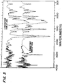
- Fig. 5 is similar to Fig. 4 and wherein the 3 mm thick polycarbonate moved at a speed ten times faster than that of Fig. 3, i.e., at 408 cm/s.
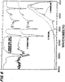
- Fig. 6 is a graphical depiction of observed emissivity spectra for beeswax moving at 40.8 cm/s with respect to the detection for both a uniform sample temperature (emission), and a cooled surface layer (transmission), and by ratioing the emission and transmission spectra (transmittance), with a transmittance spectrum recorded photoacoustically being included for reference.
- Fig. 7 is a graphical depiction of transmittance spectra of 40.8 cm/s, 3-mm-thick poly[(methyl methacrylate)-co-(butyl methacrylate)] composition materials with a 23°C bulk temperature wherein compositions (a-k) are (top to bottom) 100.0, 93.1, 85.7, 77.8, 69.2, 60.0, 50.0, 39.1, 27.3, 14.3, and 0.0 mole percent methyl methacrylate.
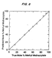
- Fig. 8 is a graph showing compositions of copolymers of methyl and butyl methacrylate predicted by cross validating principal component regressions of 1100 to 790 cm ⁇ 1 region of the spectra in Figure 7 plotted against the known sample compositions.
- Fig. 1 illustrates an embodiment of the invention which can be utilized to analyze either stationary or moving material.
- the sample or material 16 to be analyzed is disposed, for example, on a material position controller 18 such as a material transporter, for example, a conveyor, rotary table or a positioning table which can be controlled to accurately position the sample material 16.
- a material position controller 18 such as a material transporter, for example, a conveyor, rotary table or a positioning table which can be controlled to accurately position the sample material 16.
- the type of sample position controller 18 depends upon the selected operation.
- a cooling jet supply and controller 20 is provided which can be operated either in a pulsed or continuous mode and a cooling jet is directed onto the material 16.
- Collection optics 26, such as are known in the art, are used to focus the infrared radiation emitted by the sample material 16 onto spectrometer/detector system 28, which system generates an electrical signal as a function of wave number of the emitted radiation.
- a computer system 30 is also provided which controls the spectrometer/detector system 28 as well as controllers 18 and 20 and processes the spectrometer/detector system 28 signals in order to obtain the chemical or physical information required from the analysis.
- the computer system 30 also control measurement components, display results and commands auxiliary systems.
- An output from the computer system may also be supplied to a display, printer or plotter 32.
- a microscope system 36 having appropriate optics for viewing the analysis area on the sample material 16, that is, the area of intersection of the cooling jet onto the material 16.
- Reference numeral 40 designates communication connections or links between the computer system 30 and other components and controls of the embodiment.
- Computer system 30 can therefore, by appropriate software, operate the cooling jet supply and control 20, sample position controller 18, spectrometer/detector system 28 and microscope system 36.
- Other components and controls can also optionally be operated by the computer system 30, as desired.
- the embodiment of Fig. 1 is flexible and adaptable to be used for different materials, and different analytical procedures.
- This embodiment can analyze moving or stationary materials and the composition of the cooling jet upon the material 16 causes transient cooling in a thin surface layer of the material 16 by pulsing the cooling jet over time, or by rapid relative motion between the cooling jet and the material 16, or by a combination of both.
- the application of the cooling jet generates a temperature differential between the cooled thin surface layer portion of the material and a lower portion of the material sufficient to alter the thermal infrared emission spectrum of the material from the black-body thermal infrared emission spectrum of the material.
- the altered thermal infrared emission spectrum of the material representative of the transmission spectrum as described above is detected while such altered thermal infrared emission spectrum is sufficiently free of self-absorption by the material of emitted infrared radiation, prior to the temperature differential propagating into the lower portion of the material to an extent such that the altered thermal infrared emission spectrum is no longer sufficiently free of self-absorption by the material of emitted infrared radiation, so that the detected altered thermal infrared emission spectrum is indicative of characteristics relating to the molecular composition of the material.
- the emitted radiation is detected and measured by the spectrometer/detector system 28 and the computer system 30 then processes the signal to obtain molecular concentrations or other physical or chemical information through correlation techniques as required by any number of different operations, such as process control, quality control, analytical chemistry, or non-destructive evaluation applications including ratioing or the like.
- the quantitative analysis may be effected utilizing commercial principle-component-regression (PCR) software (CIRCOM from Perkin-Elmer).
- the spectrometer/detector system 28 may be any suitable type of spectrophotometer such as a Perkin-Elmer 1800 spectrophotometer having a wide-band liquid-nitrogen-cooled HgCdTe detector.
- the computer system 30 can include appropriate computers utilizing software and complementary data for deriving different material characteristics from infrared emission spectra. Additionally, such system can utilize appropriate software, displays, complementary data and servosystems for enabling decision making and for transmitting and executing commands based on the infrared spectra.
- the sample material 16 to be analyzed is moved on a conveyor belt 18 or may be attached to a rotating disk, for example, and the cooling jet provided by the cooling jet supply and controller 20 is directed onto the surface of the sample material whereby the relative motion between the sample material and the impingement of the cooling jet on the surface of the material which is sweeping past the impingement point of the cooling jet effects transient cooling in a thin surface layer of the sample material.
- Radiation emitted by the sample material is focused by the collection optics 26 on the infrared spectrometer detector system 28.
- System 28 and the computer system 30 measures the emitted radiation intensity as a function of wavenumber in terms of an electrical signal with the computer system 30 providing an output to peripherals (display printer, and/or plotter 32) to display and record the data.
- the computer system 30 processes the infrared data to determine various material properties.
- the computer system 30 uses communication or command links 40 to control various components of the measurement system, for example, the cooling jet supply and controller 20, and to control other systems, such as processing equipment (not shown) based upon material properties determined by the on-line measurements.
- the embodiment of Fig. 1 can also be used on a stationary sample material 16 which stationary measurement mode is appropriate for use in analytical laboratories where a moving stream of material 16 is not present.
- the cooling jet supply and controller 20 is pulsed with a pulse time which is short on the scale of a pulse repetition time.
- a heating jet may be utilized to prevent the long term cooling in the sample material 16 and thereby return the sample material to its previous temperature.
- the microscope viewing system 36 can be employed to position the impingement spot of the cooling jet at a precise location on the sample 16 which enables microanalysis.
- the stationary sample measurement mode is similar to the moving sample embodiment described above.
- the spectrometer/detector system 28 sampling under control of the computer system 30.
- the detection by the spectrometer/detector system is gated in accordance with the application of the cooling pulse to detect the transient altered thermal emission of infrared radiation from the material for a short time period, thereby avoiding detection of emissions effected by self-absorption.
- Other techniques may also be utilized and the spectrometer/detector may be provided with suitable filters.
- Fig. 2 shows another embodiment of the present invention for a better understanding of the invention and this embodiment was used to generate the spectra illustrated in Figs. 3-6.
- the illustrated curves showing the transmission spectra, on the scale, used do not show clearly the variation, especially in the high wavenumbers as, for example, wavenumbers 2000-4000 of curve C in Fig. 6.
- such variations do exist and are clearly shown in the resultant transmittance curve D of Fig. 6.
- solid sample material to be analyzed in the form of a rotating disk 42 is secured to a variable speed motor 44 through an axle 46 for spinning the disk 42.
- the normal infrared source of a Perkin-Elmer 1800 spectrophotometer was removed and the disk of the sample material 42 was positioned so that the spectrophotometer 50 viewed the sample normal to the surface thereof.
- the sample disk was mounted on the shaft 46 of the variable speed motor 44 and spun to simulate a continuous flow of fresh material through the spectrometer field of view.
- a salt (KCl) window 52 covered the spectrometer port without any other optics being utilized.
- the cooling jet supply was in the form of helium being chilled by passage through a liquid nitrogen bath 54 at 0.10 to 0.14 L/s.
- the stream of cold helium was directed onto the surface of the sample material disk 42 within the spectrometer field of view by a 1 mm inner-diameter tube 58 under control of a controller 56.
- the end of the tube 58 was positioned within 2 mm of the sample surface and was positioned at a 45° angle with respect to both the sample surface and the direction of motion of the sample to the field of view which is indicated by the arrow direction.
- a jet of heated nitrogen flowing from a heater 60 was directed onto the cooled or chilled surface track left by the cold jet.
- the temperature and flow rate of the nitrogen were adjusted so that the nitrogen raised the temperature of the surface of the sample material disk 42 to approximately the temperature value thereof prior to application of the cold jet.
- the rotating sample disc 42 mimics a continuous flow of uniform-temperature material into the spectrometer field of view having a cold jet 22 applied thereto.
- a heat gun 62 was directed onto the rear of the sample disk 42 in order to raise the bulk sample temperature above room temperature, if desired.
- Figs. 4 and 6 show curves (A) representing reference transmittance spectra which were not recorded by conventional transmission since the samples were optically thick. Instead, absorbance spectra were recorded using an MTEC Model 200 photoacoustic detector mounted in the spectrophotometer with its normal infrared source, and the absorbance spectra were converted mathematically to transmittance spectra. The absorbance spectra were recorded at 0.05 cm/s optical-path-difference velocity and 8 cm ⁇ 1 nominal resolution by accumulating 32 scans.
- Fig. 3 shows both emission and transmission spectra for 3 a mm-thick polycarbonate (Lexan) travelling at 40.8 cm/s through the spectrometer field of view, which spectra have not been corrected for the response function of the spectrometer and detector.
- Two emission curves (A and B) were recorded with the sample at a uniform temperature of 23°C (curve A) and 132°C (curve B) so that the emission curves represent black-body emission.
- the 23°C emission spectrum (curve A) is virtually identical to that of a black-body emission spectrum whereas the 132°C spectrum (curve B) has some structure characteristic of polycarbonate, but again is considered representative of a black-body emission spectrum.
- the transmission spectra in accordance with the present invention have all of the characteristic features of polycarbonate with curve C representing the transmission spectra for the 23°C temperature and curve D the transmission spectrum for the 132°C temperature.
- the emission and transmission spectrum for curves A and C and curves B and D, respectively, were ratioed to produce the transmittance spectra curves B and C, respectively, as shown in Fig. 4.
- Fig. 4 shows transmittance spectra of the sample polycarbonate disk at the temperatures of 23°C (curve A) and 132°C (curve B) based upon ratioing with the emission spectra at such uniform temperatures, but at a 408 cm/s sample velocity representing 10 times the speed utilized in accordance with Figs. 3 and 4.
- the spectra in Fig. 5 displayed less saturation than those in Fig. 4, including the reference photoacoustic spectrum.
- the cooled layer is both thinner and not as cold so that the strength of absorption is reduced. Accordingly, the higher speed spectra have smaller signal-to-noise ratios.
- Fig. 6 shows spectra for yellow beeswax (Fisher Scientific) which melts at 62°C to 65°C and which is optically a highly scattering material.
- the beeswax was formed as a disk of an average 3 mm thickness at room temperature, as the sample 42 in Fig. 2 and rotated at a speed of 40.8 cm/s through the spectrometer field of view.
- the transmittance spectrum using a photoacoustic detector is shown in curve A with the emission spectrum for the sample material at 23°C being shown in curve B and the transmission spectra in accordance with the present invention being shown in curve C.
- the transmittance spectrum (curve D) was derived by ratioing the emission and transmission spectra (curves B and C).
- the spectra of eleven copolymers of methyl methacrylate and n-butyl methacrylate were recorded utilizing the embodiment of Fig. 2 and analyzed by principal component regression (PCR).
- the sample disks averaged 3 mm in thickness and had compositions of 0.0, 14.3, 27.3, 39.1, 50.0, 60.0, 69.2, 77.8, 85.7, 93.1, and 100.0 mole percent methyl methacrylate.
- the transmission spectra were recorded with the disks at room temperature (23°C) and moving at 40.8 cm/s.
- the transmittance spectra are shown in Fig.
- the present invention produces quantitatively accurate spectra from optically thick, moving materials. Quantitative analysis is possible even at the low thermal-emission intensities from room temperature samples wherein a dynamic thermal gradient is induced so that the spectroscopic behavior of an optically thin layer of material differs from that of the rest of the sample.
- the present invention overcomes the problem of high optical density in solids that previously prevented the real-time infrared analysis of most solid samples and is insensitive to the reflectance and optical-scattering properties of samples while functioning in real time without sample preparation and does not involve raising sample temperature, so it can be applied where elevated temperatures cannot be used.
Landscapes
- Health & Medical Sciences (AREA)
- Nuclear Medicine, Radiotherapy & Molecular Imaging (AREA)
- Physics & Mathematics (AREA)
- Life Sciences & Earth Sciences (AREA)
- Chemical & Material Sciences (AREA)
- Analytical Chemistry (AREA)
- Biochemistry (AREA)
- General Health & Medical Sciences (AREA)
- General Physics & Mathematics (AREA)
- Immunology (AREA)
- Pathology (AREA)
- Investigating Or Analysing Materials By Optical Means (AREA)
- Investigating Or Analyzing Materials Using Thermal Means (AREA)
Applications Claiming Priority (2)
| Application Number | Priority Date | Filing Date | Title |
|---|---|---|---|
| US546738 | 1990-07-02 | ||
| US07/546,738 US5070242A (en) | 1989-01-13 | 1990-07-02 | Apparatus and method for transient thermal infrared spectrometry |
Publications (2)
| Publication Number | Publication Date |
|---|---|
| EP0465082A2 true EP0465082A2 (de) | 1992-01-08 |
| EP0465082A3 EP0465082A3 (en) | 1992-03-11 |
Family
ID=24181791
Family Applications (1)
| Application Number | Title | Priority Date | Filing Date |
|---|---|---|---|
| EP19910305707 Withdrawn EP0465082A3 (en) | 1990-07-02 | 1991-06-24 | Apparatus and method for transient thermal infrared spectrometry |
Country Status (2)
| Country | Link |
|---|---|
| EP (1) | EP0465082A3 (de) |
| JP (1) | JPH04232450A (de) |
Cited By (1)
| Publication number | Priority date | Publication date | Assignee | Title |
|---|---|---|---|---|
| EP0529925A3 (en) * | 1991-08-23 | 1993-05-19 | Iowa State University Research Foundation, Inc. | Apparatus and method for transient thermal infrared spectrometry of flowable enclosed materials |
Family Cites Families (2)
| Publication number | Priority date | Publication date | Assignee | Title |
|---|---|---|---|---|
| US4496839A (en) * | 1982-11-03 | 1985-01-29 | Spectral Sciences Incorporated | System and method for remote detection and identification of chemical species by laser initiated nonresonant infrared spectroscopy |
| US4578584A (en) * | 1984-01-23 | 1986-03-25 | International Business Machines Corporation | Thermal wave microscopy using areal infrared detection |
-
1991
- 1991-06-24 EP EP19910305707 patent/EP0465082A3/en not_active Withdrawn
- 1991-07-01 JP JP3160481A patent/JPH04232450A/ja active Pending
Cited By (1)
| Publication number | Priority date | Publication date | Assignee | Title |
|---|---|---|---|---|
| EP0529925A3 (en) * | 1991-08-23 | 1993-05-19 | Iowa State University Research Foundation, Inc. | Apparatus and method for transient thermal infrared spectrometry of flowable enclosed materials |
Also Published As
| Publication number | Publication date |
|---|---|
| EP0465082A3 (en) | 1992-03-11 |
| JPH04232450A (ja) | 1992-08-20 |
Similar Documents
| Publication | Publication Date | Title |
|---|---|---|
| US5070242A (en) | Apparatus and method for transient thermal infrared spectrometry | |
| US5191215A (en) | Apparatus and method for transient thermal infrared spectrometry of flowable enclosed materials | |
| Bacci | Fibre optics applications to works of art | |
| US4652755A (en) | Method and apparatus for analyzing particle-containing gaseous suspensions | |
| JP3536203B2 (ja) | ウェーハの結晶欠陥測定方法及び装置 | |
| Zhang et al. | Improving coal/gangue recognition efficiency based on liquid intervention with infrared imager at low emissivity | |
| Jones et al. | Quantitative analysis of solids in motion by transient infrared emission spectroscopy using hot-gas jet excitation | |
| US11333600B2 (en) | Analysis method, analysis apparatus, printer, and print system | |
| US4591718A (en) | Photothermal method for in situ microanalysis of the chemical composition of coal samples | |
| CN214749784U (zh) | 一种对于材料微区的吸收光谱检测装置 | |
| CN101561325B (zh) | 聚合物本体温度的检测方法 | |
| EP0465082A2 (de) | Vorrichtung und Verfahren für kurzzeitige thermische Infrarot-Spectrometrie | |
| Jones et al. | Transient infrared transmission spectroscopy | |
| US3499153A (en) | Nondestructive testing of materials by infrared radiation | |
| Li et al. | A novel extraction and evaluation method for melt pool images in laser powder bed fusion | |
| CA2045733A1 (en) | Apparatus and method for transient thermal infrared spectrometry | |
| US6988393B2 (en) | Apparatus for determining rheological properties | |
| McClelland et al. | Apparatus and method for transient thermal infrared spectrometry | |
| EP0406399A1 (de) | Vorrichtung und verfahren zur transienten thermischen infrarot-emissionsspektroskopie | |
| McClelland et al. | Apparatus and method for transient thermal infrared emission spectrometry | |
| Zhang et al. | Novel carbon dioxide gas sensor based on infrared absorption | |
| Vreugdenhil et al. | Applications of vibrational spectroscopy to the analysis of novel coatings | |
| JPH07181135A (ja) | 流動性材料の分析を可能とする装置および方法 | |
| Schwiesow | Raman scattering from pollutant gases and air-water interfaces | |
| Herrmann et al. | Trace analysis in gases by laser-induced Schlieren technique |
Legal Events
| Date | Code | Title | Description |
|---|---|---|---|
| PUAI | Public reference made under article 153(3) epc to a published international application that has entered the european phase |
Free format text: ORIGINAL CODE: 0009012 |
|
| AK | Designated contracting states |
Kind code of ref document: A2 Designated state(s): DE FR GB |
|
| PUAL | Search report despatched |
Free format text: ORIGINAL CODE: 0009013 |
|
| AK | Designated contracting states |
Kind code of ref document: A3 Designated state(s): DE FR GB |
|
| 17P | Request for examination filed |
Effective date: 19920804 |
|
| STAA | Information on the status of an ep patent application or granted ep patent |
Free format text: STATUS: THE APPLICATION HAS BEEN WITHDRAWN |
|
| 18W | Application withdrawn |
Withdrawal date: 19930831 |