EP0465033A1 - Quick connect/release/adjust buckle - Google Patents
Quick connect/release/adjust buckle Download PDFInfo
- Publication number
- EP0465033A1 EP0465033A1 EP91305378A EP91305378A EP0465033A1 EP 0465033 A1 EP0465033 A1 EP 0465033A1 EP 91305378 A EP91305378 A EP 91305378A EP 91305378 A EP91305378 A EP 91305378A EP 0465033 A1 EP0465033 A1 EP 0465033A1
- Authority
- EP
- European Patent Office
- Prior art keywords
- strap
- female member
- aperture
- attaching
- buckle device
- Prior art date
- Legal status (The legal status is an assumption and is not a legal conclusion. Google has not performed a legal analysis and makes no representation as to the accuracy of the status listed.)
- Withdrawn
Links
Images


Classifications
-
- A—HUMAN NECESSITIES
- A44—HABERDASHERY; JEWELLERY
- A44B—BUTTONS, PINS, BUCKLES, SLIDE FASTENERS, OR THE LIKE
- A44B11/00—Buckles; Similar fasteners for interconnecting straps or the like, e.g. for safety belts
-
- A—HUMAN NECESSITIES
- A44—HABERDASHERY; JEWELLERY
- A44B—BUTTONS, PINS, BUCKLES, SLIDE FASTENERS, OR THE LIKE
- A44B11/00—Buckles; Similar fasteners for interconnecting straps or the like, e.g. for safety belts
- A44B11/02—Buckles; Similar fasteners for interconnecting straps or the like, e.g. for safety belts frictionally engaging surface of straps
- A44B11/04—Buckles; Similar fasteners for interconnecting straps or the like, e.g. for safety belts frictionally engaging surface of straps without movable parts
-
- A—HUMAN NECESSITIES
- A44—HABERDASHERY; JEWELLERY
- A44B—BUTTONS, PINS, BUCKLES, SLIDE FASTENERS, OR THE LIKE
- A44B18/00—Fasteners of the touch-and-close type; Making such fasteners
Definitions
- the present invention relates to buckles and more specifically to buckles which are easy to adjust and can be connected quickly.
- Buckles are used for securing many different items from pants to safety belts.
- An early style of buckle was two D-rings attached to one end of a strap and the other end of the strap was threaded through the D-rings around the outside of the one D-ring and then back through the center of the second D-ring. The strap is then pulled tight.
- a similar buckle is shown in United States Patent No. 4,878,274 issued on November 7, 1989 to H. R. Patricy which shows a strap having a hook and loop type fastener thereon which is threaded through one D-ring and secured by bringing the two portions of the hook and loop type fastener together.
- a particular disadvantage of both types of buckles is that it can be difficult to thread one end of the strap through the D-ring.
- a buckle device including a male strap member which has a longitudinal axis, distal end portion and an intermediate portion.
- a female member of the device has an aperture formed therein dimensioned to receive the strap member, a strap engaging portion adjacent to the aperture for restraining movement of the strap member, a slot extending through an outer edge of the female member and in communication with apertures for guiding the strap member into engagement with the strap engaging portion and a protrusion extending inwardly from the outer edge of the female member for preventing the strap in the aperture from moving into the slot.
- the strap distal end portion releasably engages the strap intermediate portion.
- a buckle includes a female member shown generally at 14.
- Female member 14 has an aperture 24 formed therein and strap engaging portion 26 adjacent to aperture 24.
- a peripheral outer edge 28 of the female member 14 has a slot 30 formed therein shown in the top of female member 14 in Figure 1.
- Slot 30 is in communication with aperture 24.
- a protrusion 29 extends inwardly from peripheral outer edge 28 adjacent to slot 30.
- Protrusion 29 has a ball 31 at its distal end portion.
- Female member 14 is further provided with an attaching slot 32 at the side of the female member opposite from aperture 24. As shown here, attaching slot 32 is rectangular in shape. Extensions 33 extend outwardly from the top and bottom edge portions of female member 14 adjacent attaching slot 32.
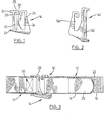
- a second embodiment of the female member of the invention is shown generally at 40 in Figure 2.
- Female member 40 is similar to that shown at 14 in Figure 1 except that slot 13 2 is proportionally longer than aperture 124.
- a third embodiment of the female member of the invention is shown generally at 50 in Figure 4.
- Female member 50 is similar to that shown at 14 in Figure 1 except that it has a rounded edge portion 52 around slot 232 rather than the extensions 33 of female member 14.
- a fourth embodiment of the female member of the invention is shown generally at 60 in Figure 10.
- Female member 60 is similar to that shown at 14 in Figure 1 except that it has a pair of slots 432 formed therein.
- Protrusion 429 is a straight downward extension from the outer edge 428 as compared to protrusion 29 of female member 14 which has a ball 31 at its distal end portion.
- a fifth embodiment of the female member of the invention is shown generally at 70 in Figures 12 and 13.
- Female member 70 is similar to that shown at 14 in Figure 1 except for the following differences.
- Female member 70 has a pair of slots 532 formed therein.
- Lower portion 72 of female member 70 has an outer rib 74 extending downwardly therefrom.
- Outer rib 74 as shown is generally triangular in shape and has a length that increases slot end to the aperture end.
- An inner rib 76 is formed in female member 70 where slot 530 is in communication with aperture 524.
- the buckle shown generally at 10 in addition to female member 14 includes a male strap member 12 and attaching strap 13.
- Male strap member 12 has a distal end portion 16 and an intermediate portion 18.
- the distal end portion 16 of the strap is adapted to be attached to the intermediate portion 18 with use of hook and loop type fasteners, commonly sold under the trade mark VELCRO.
- One portion 20 of the hook and loop type fastener is attached to the distal end portion 16 and the other portion 22 of the hook and loop type fastener is attached to intermediate portion 18.
- Hook and loop type fasteners can best be seen in Figure 11 wherein one portion 420 is attached to distal end portion 416.
- male strap member 80 is shown generally at 80 in Figure 14.
- Male strap member 80 is similar to that shown at 412 in Figure 11 except for the following differences.
- Distal end portion 616 has a series of apertures 82 formed therein.
- Intermediate portion 618 has a series of studs 84 which extend outwardly therefrom and are adapted to engage apertures 82.
- attaching strap 13 is threaded through slot 28, folded over and attached to itself by stitching 36.
- a second method of attaching the female member to an attaching strap is shown in Figure 4.
- the attaching strap has a flexible extension 54 attached thereto. Flexible extension is threaded through slot 232 and both ends of extension 54 are attached to attaching strap 213.
- a third method of attaching the female member is shown in Figure 7 wherein female member 14 is attached to a first piece of material 56.
- the method of attaching is similar to that shown in Figure 3 except that stitching 336 attaches the attaching strap 313 to itself and to material 56.
- Female member 14 is attached so at to allow pivotal movement of the female member 14 outwardly from material 56, but restrain rotational movement of the female member 14 in a direction transverse to the pivotal movement of the female member 14.
- Male strap member 12 is attached to second piece of material 58 by any conventional method. In such a manner, buckle 10 can be used to attach the first piece of material 56 to the second piece of material 58.
- FIG. 8 A fourth method of attaching the female member is shown in Figure 8 wherein female member 14 is attached to a first piece of material 56.
- Female member 14 is stitched directly onto material 56 by way of stitches 64.
- Male strap member 12 is attached to material 58 by any conventional method.
- a fifth method of attaching female member is shown in Figure 11 wherein female member 60 is attached to attaching strap 413 by threading an end through one slot 432 and then back through the other slot 432 and then attaching strap 413 to itself by stitching 436.
- male strap member 12 is inserted through slot 30 as shown in Figure 9a. It is then positioned in aperture 24 as shown in Figure 9b. The strap member 12 is then pulled tight and secured as shown in Figure 9c.
- Extensions 33 and 133 of female member 14 and 40 respectively and the pair of slots 432 and 532 of female member 60 and 70 respectively are both provided to aid in restraining 'rotational movement of female member when the female member is attached to a piece of material.
- the attaching methods shown in Figures 7 and 8 can be adapted to be used with any of female members 14, 40, 60 and 70 so as to allow for pivotal movement away from the material and restrain rotational movement in a direction transverse to the pivotal movement. It is important to restrain the rotational movement of the female member 14 so that one hand can be used to attach male strap member 12 to female member 14. If female member 14 can rotate then another hand would be needed to steady female member 14 while male strap member 12 is inserted therein. It will be appreciated by someone skilled in the art that the attaching method shown in Figure 4 could not be adapted to be used with one hand.
- the female member is made from high strength plastic including nylon. However, it could also be made from steel, such as 1/8 ⁇ plated roundstock, or any other suitable material.
- the strap member 12 is preferably made from nylon strapping but it could also be made from any other suitable materials. Steel buckles can be machine formed or cast while plastic buckles are moulded.
- the size of the present buckle device can vary but typically the width will range from 1/2 to 2 inches.
- the preferred buckle device described herein can be operated or used with one hand only, permitting its use by the handicapped or when the use of the other hand is required for other purposes. Also the buckle can be operated by one having diminished motor control or by a gloved hand.
- the preferred buckle device has a cinching feature allowing for tight and secure fastening.
- the female member 14 may not have a overall square shape, rather the portion having the pair of slots 32 formed therein could be larger or smaller than the portion having aperture 24 formed therein.
Landscapes
- Buckles (AREA)
- Tires In General (AREA)
Abstract
A buckle device which is easy to adjust and can be connected quickly is disclosed. The buckle device has a male strap member (12) which has a longitudinal axis, distal end portion (16) and in intermediate portion (18). The female member (14) has an (24) aperture (24) formed therein dimensioned to receive the strap member (12), a strap engaging portion adjacent to the aperture for restraining movement of the strap member, a slot (30) extending through an outer edge of the female member and in communication with apertures for guiding the strap member into engagement with the strap engaging portion and a protrusion (31) extending inwardly from the outer edge of the female member (14) for preventing the strap in the aperture from moving into the slot (30). The strap distal end portion (16) releasably engages the strap intermediate portion. (18)
Description
- The present invention relates to buckles and more specifically to buckles which are easy to adjust and can be connected quickly.
- Buckles are used for securing many different items from pants to safety belts. An early style of buckle was two D-rings attached to one end of a strap and the other end of the strap was threaded through the D-rings around the outside of the one D-ring and then back through the center of the second D-ring. The strap is then pulled tight. A similar buckle is shown in United States Patent No. 4,878,274 issued on November 7, 1989 to H. R. Patricy which shows a strap having a hook and loop type fastener thereon which is threaded through one D-ring and secured by bringing the two portions of the hook and loop type fastener together. A particular disadvantage of both types of buckles is that it can be difficult to thread one end of the strap through the D-ring.
- Another securement system is shown in United States patent No. 3,057,354 issued on October 9, 1962 to D.R. Roberts et al. which shows a supporting device for a sanitary napkin including conventional sanitary napkin attaching clips and adjustable straps. The length of the straps are adjustable by the use of hook and loop type fasteners. One end of the sanitary napkin is attached to a clip by threading it through the aperture and pushing it down onto the spikes, in a fashion somewhat similar to the use of a D-ring, and then securing it in the C-shaped opening. A particular disadvantage of this attaching system is that it can be difficult to position the one end of the sanitary napkin in the clip.
- Another fastening system is shown in United States patent No. 1,187,132 issued June 13, 1916 to M.C. Caulkins which shows a system for supporting stockings. The stocking is clamped between a male member and female member. A particular disadvantage of this system is that it can only be used to connect members which do not have a lot of strain put on them.
- Taken alone or in combination none of these prior art references show a buckle which can be quickly connected, quickly readjusted and quickly released and which can withstand a certain amount of force. Further, none of these prior art references taken alone or together show a buckle which allows for one hand operation.
- It is an object of the invention to provide a buckle device that can be quickly connected and adjusted.
- In accordance with one aspect of the invention there is provided a buckle device including a male strap member which has a longitudinal axis, distal end portion and an intermediate portion. A female member of the device has an aperture formed therein dimensioned to receive the strap member, a strap engaging portion adjacent to the aperture for restraining movement of the strap member, a slot extending through an outer edge of the female member and in communication with apertures for guiding the strap member into engagement with the strap engaging portion and a protrusion extending inwardly from the outer edge of the female member for preventing the strap in the aperture from moving into the slot. The strap distal end portion releasably engages the strap intermediate portion.
- The invention is illustrated in particular and preferred embodiments by reference to the accompanying drawings:
- Figure 1 is a side view of a first embodiment of a female member of the buckle of the present invention;
- Figure 2 is a side view of a second embodiment of a female member of the buckle;
- Figure 3 is a side view of the female member of Figure 1 and a male strap member together comprising the buckle and showing a first method of attaching a strap member to the female member;
- Figure 4 is a side view of a third embodiment of a female member and a male strap member together comprising the buckle and showing a second method of attaching a strap member to the female member;
- Figure 5 is a side view of the first embodiment of the female member and the male strap member of the buckle before the male strap member is attached to the female member and showing the first method of attaching a strap member to the female member;
- Figure 6 is a side view of the first embodiment of the female member having both ends of the male strap member attached thereto and showing the first method of attaching a strap member to the female member;
- Figure 7 is a side view of the first embodiment of the female member having the strap member attached thereto and showing a third method of attaching the female member to a strap member and a first piece of material and showing the male strap member attached to a second piece of material;
- Figure 8 is a side view of the first embodiment of the female member having a strap member attached thereto and showing a fourth method of attaching the female member to a first piece of material and the male strap member is attached to a second piece of material;
- Figures 9a, 9b and 9c show the steps of attaching the first embodiment of the female member to the strap member;
- Figure 10 is a perspective view of a fourth embodiment of a female member of the buckle;
- Figure 11 is a perspective view of the male strap member of the buckle being secured to the fourth embodiment of the female member which has a strap member attached thereto;
- Figure 12 is a perspective view of a fifth embodiment of a female member of the buckle as seen from above;
- Figure 13 is a perspective view of the fifth embodiment of the female member shown in Figure 12 as seen from below; and
- Figure 14 is a perspective view of the fourth embodiment of the female member shown in Figure 11 but showing an alternate embodiment of the male strap member.
- Preferred embodiments of the buckle will now be described with reference to the figures wherein numerals raised by a multiple of 100 refer to like parts.
- Referring to Figure 1, a buckle includes a female member shown generally at 14.
Female member 14 has anaperture 24 formed therein and strap engagingportion 26 adjacent toaperture 24. A peripheralouter edge 28 of thefemale member 14 has aslot 30 formed therein shown in the top offemale member 14 in Figure 1.Slot 30 is in communication withaperture 24. Aprotrusion 29 extends inwardly from peripheralouter edge 28 adjacent toslot 30.Protrusion 29 has aball 31 at its distal end portion.Female member 14 is further provided with an attachingslot 32 at the side of the female member opposite fromaperture 24. As shown here, attachingslot 32 is rectangular in shape.Extensions 33 extend outwardly from the top and bottom edge portions offemale member 14 adjacent attachingslot 32. - A second embodiment of the female member of the invention is shown generally at 40 in Figure 2.
Female member 40 is similar to that shown at 14 in Figure 1 except thatslot 13 2 is proportionally longer thanaperture 124. - A third embodiment of the female member of the invention is shown generally at 50 in Figure 4.
Female member 50 is similar to that shown at 14 in Figure 1 except that it has arounded edge portion 52 aroundslot 232 rather than theextensions 33 offemale member 14. - A fourth embodiment of the female member of the invention is shown generally at 60 in Figure 10.
Female member 60 is similar to that shown at 14 in Figure 1 except that it has a pair ofslots 432 formed therein.Protrusion 429 is a straight downward extension from theouter edge 428 as compared toprotrusion 29 offemale member 14 which has aball 31 at its distal end portion. - A fifth embodiment of the female member of the invention is shown generally at 70 in Figures 12 and 13.
Female member 70 is similar to that shown at 14 in Figure 1 except for the following differences.Female member 70 has a pair ofslots 532 formed therein.Lower portion 72 offemale member 70 has anouter rib 74 extending downwardly therefrom.Outer rib 74 as shown is generally triangular in shape and has a length that increases slot end to the aperture end. Aninner rib 76 is formed infemale member 70 whereslot 530 is in communication withaperture 524. - Referring to Figure 3, the buckle shown generally at 10 in addition to
female member 14 includes amale strap member 12 and attachingstrap 13.Male strap member 12 has adistal end portion 16 and anintermediate portion 18. Thedistal end portion 16 of the strap is adapted to be attached to theintermediate portion 18 with use of hook and loop type fasteners, commonly sold under the trade mark VELCRO. Oneportion 20 of the hook and loop type fastener is attached to thedistal end portion 16 and theother portion 22 of the hook and loop type fastener is attached tointermediate portion 18. Hook and loop type fasteners can best be seen in Figure 11 wherein oneportion 420 is attached todistal end portion 416. - An alternate embodiment of the male strap member of the invention is shown generally at 80 in Figure 14.
Male strap member 80 is similar to that shown at 412 in Figure 11 except for the following differences.Distal end portion 616 has a series ofapertures 82 formed therein. Intermediate portion 618 has a series ofstuds 84 which extend outwardly therefrom and are adapted to engageapertures 82. - Referring to Figure 3, attaching
strap 13 is threaded throughslot 28, folded over and attached to itself by stitching 36. A second method of attaching the female member to an attaching strap is shown in Figure 4. The attaching strap has aflexible extension 54 attached thereto. Flexible extension is threaded throughslot 232 and both ends ofextension 54 are attached to attachingstrap 213. - A third method of attaching the female member is shown in Figure 7 wherein
female member 14 is attached to a first piece ofmaterial 56. The method of attaching is similar to that shown in Figure 3 except thatstitching 336 attaches the attachingstrap 313 to itself and tomaterial 56.Female member 14 is attached so at to allow pivotal movement of thefemale member 14 outwardly frommaterial 56, but restrain rotational movement of thefemale member 14 in a direction transverse to the pivotal movement of thefemale member 14.Male strap member 12 is attached to second piece ofmaterial 58 by any conventional method. In such a manner, buckle 10 can be used to attach the first piece ofmaterial 56 to the second piece ofmaterial 58. - A fourth method of attaching the female member is shown in Figure 8 wherein
female member 14 is attached to a first piece ofmaterial 56.Female member 14 is stitched directly ontomaterial 56 by way of stitches 64.Male strap member 12 is attached tomaterial 58 by any conventional method. - A fifth method of attaching female member is shown in Figure 11 wherein
female member 60 is attached to attachingstrap 413 by threading an end through oneslot 432 and then back through theother slot 432 and then attachingstrap 413 to itself by stitching 436. - The attachment of
male strap member 12 tofemale member 14 will now be discussed with reference to Figures 9a to 9c.Male strap member 12 is inserted throughslot 30 as shown in Figure 9a. It is then positioned inaperture 24 as shown in Figure 9b. Thestrap member 12 is then pulled tight and secured as shown in Figure 9c. - As will be appreciated by someone skilled in the art and as shown in Figures 1, 2, 4, 10 and 12, there are a number of different configurations of the female members of the invention. It will be appreciated that further modifications could be made without departing from the scope of the invention. Some of the advantages of these configurations will now be discussed.
-
Extensions 33 and 133 offemale member slots female member female members female member 14 so that one hand can be used to attachmale strap member 12 tofemale member 14. Iffemale member 14 can rotate then another hand would be needed to steadyfemale member 14 whilemale strap member 12 is inserted therein. It will be appreciated by someone skilled in the art that the attaching method shown in Figure 4 could not be adapted to be used with one hand. - Preferably the female member is made from high strength plastic including nylon. However, it could also be made from steel, such as 1/8˝ plated roundstock, or any other suitable material. The
strap member 12 is preferably made from nylon strapping but it could also be made from any other suitable materials. Steel buckles can be machine formed or cast while plastic buckles are moulded. - The size of the present buckle device can vary but typically the width will range from 1/2 to 2 inches.
- It will be appreciated that the preferred buckle device described herein can be operated or used with one hand only, permitting its use by the handicapped or when the use of the other hand is required for other purposes. Also the buckle can be operated by one having diminished motor control or by a gloved hand. The preferred buckle device has a cinching feature allowing for tight and secure fastening.
- Having described a preferred embodiment of the invention it will be appreciated that various modifications may be made to the structure described. For example, the
female member 14 may not have a overall square shape, rather the portion having the pair ofslots 32 formed therein could be larger or smaller than theportion having aperture 24 formed therein.
Claims (11)
- A buckle device comprising:
a male strap member having a longitudinal axis, a distal end portion and an intermediate portion;
a female member having an aperture formed therein dimensioned to receive the strap member, a strap engaging portion adjacent to the aperture for restraining movement of the strap member, a slot extending through an outer edge of the female member and in communication with said aperture, the slot being adapted to guide the strap member into said aperture, and a protrusion extending inwardly from an outer edge of the female member for preventing the strap in said aperture from moving into said slot; and
strap attaching means for releasably attaching the strap distal end portion and the strap intermediate portion. - A buckle device according to claim 1, wherein the female member is attached to a piece of material so as to allow pivotal movement of the female member outwardly from the material and to restrain rotational movement of the female member in a direction transverse to the direction of pivot.
- A buckle device according to claim 1, wherein the strap attaching means is a hook and loop type fastener and one portion of the hook and loop type fastener is attached to the distal end portion of the strap member and a second portion of the hook and loop type fastener is attached to the intermediate portion of the strap member.
- A buckle device according to claim 1 wherein the strap attaching means includes a strap aperture formed in said distal end portion and a stud extending outwardly from the intermediate portion of the strap member adapted to engage the strap aperture.
- A buckle device according to claim 4 wherein the distal end portion of the strap has a plurality of strap apertures formed therein and said attaching means includes a plurality of studs extending outwardly from the intermediate portion of the stud.
- A buckle device according to claim 1 wherein the female member has an attaching slot formed therein on the side of the female member opposite said aperture, said attaching slot enabling the female member to be attached to one of an attaching strap, a piece of material and a combination of strap and piece of material.
- A buckle device according to claim 6 including a pair of extensions extending outwardly from bottom and top edge portions of the female member adjacent said attaching slot.
- A buckle device according to claim 1 wherein the female member has a pair of attaching slots formed thereon on the side of the female member opposite said aperture, said attaching slots enabling the female member to be attached to one of an attaching strap, a piece of material and a combination of strap and piece of material.
- A buckle device according to claim 1 wherein a distal end portion of the protrusion has a ball formed thereon.
- A buckle device according to claim 1 wherein the female member has an outer ridge extending downwardly therefrom.
- A buckle device according to claim 10 wherein the female member has an inner ridge at the point where the slot is in communication with the aperture.
Applications Claiming Priority (2)
| Application Number | Priority Date | Filing Date | Title |
|---|---|---|---|
| CA 2018972 CA2018972A1 (en) | 1990-06-13 | 1990-06-13 | Quick connect/release/adjust buckle |
| CA2018972 | 1990-06-13 |
Publications (1)
| Publication Number | Publication Date |
|---|---|
| EP0465033A1 true EP0465033A1 (en) | 1992-01-08 |
Family
ID=4145227
Family Applications (1)
| Application Number | Title | Priority Date | Filing Date |
|---|---|---|---|
| EP91305378A Withdrawn EP0465033A1 (en) | 1990-06-13 | 1991-06-13 | Quick connect/release/adjust buckle |
Country Status (2)
| Country | Link |
|---|---|
| EP (1) | EP0465033A1 (en) |
| CA (2) | CA2018972A1 (en) |
Cited By (7)
| Publication number | Priority date | Publication date | Assignee | Title |
|---|---|---|---|---|
| WO1995009547A1 (en) * | 1993-10-01 | 1995-04-13 | Century Products Company | Splitter plate |
| GB2337727A (en) * | 1998-04-21 | 1999-12-01 | Peter Sesay | Seat belt buckle |
| WO1999065351A1 (en) * | 1998-06-17 | 1999-12-23 | Susanne Kupske | Joining device for joining two garment parts, especially of children's clothing |
| US7100249B2 (en) | 2003-09-26 | 2006-09-05 | Lowe Alpine Holdings Limited | Buckle |
| NL2001966C2 (en) * | 2008-09-09 | 2010-03-15 | Attema Kunststoffenind | A holder for multiple optical fibre connections. |
| KR20230073055A (en) * | 2021-11-18 | 2023-05-25 | 주식회사 투비레어 | Strap Clip that's Easy to Combine and Release |
| US11759029B2 (en) | 2020-08-07 | 2023-09-19 | Wonderland Switzerland Ag | Baby carriage and quick release pillow |
Citations (5)
| Publication number | Priority date | Publication date | Assignee | Title |
|---|---|---|---|---|
| US2212862A (en) * | 1939-12-18 | 1940-08-27 | Adjusta Company | Buckle |
| US2285714A (en) * | 1941-08-07 | 1942-06-09 | Adjusta Company | Adjustable buckle |
| US2439274A (en) * | 1947-09-13 | 1948-04-06 | Spector Theodore | Wrist band or strap for watches |
| FR1341729A (en) * | 1962-10-03 | 1963-11-02 | Meto Ges Kind & Sohne Fa | Tightening loop for tying packages or similar items |
| CH487613A (en) * | 1968-09-19 | 1970-03-31 | Gattlen Alfred | Strap |
-
1990
- 1990-06-13 CA CA 2018972 patent/CA2018972A1/en not_active Abandoned
-
1991
- 1991-06-07 CA CA 2043286 patent/CA2043286A1/en not_active Abandoned
- 1991-06-13 EP EP91305378A patent/EP0465033A1/en not_active Withdrawn
Patent Citations (5)
| Publication number | Priority date | Publication date | Assignee | Title |
|---|---|---|---|---|
| US2212862A (en) * | 1939-12-18 | 1940-08-27 | Adjusta Company | Buckle |
| US2285714A (en) * | 1941-08-07 | 1942-06-09 | Adjusta Company | Adjustable buckle |
| US2439274A (en) * | 1947-09-13 | 1948-04-06 | Spector Theodore | Wrist band or strap for watches |
| FR1341729A (en) * | 1962-10-03 | 1963-11-02 | Meto Ges Kind & Sohne Fa | Tightening loop for tying packages or similar items |
| CH487613A (en) * | 1968-09-19 | 1970-03-31 | Gattlen Alfred | Strap |
Cited By (10)
| Publication number | Priority date | Publication date | Assignee | Title |
|---|---|---|---|---|
| WO1995009547A1 (en) * | 1993-10-01 | 1995-04-13 | Century Products Company | Splitter plate |
| US5432985A (en) * | 1993-10-01 | 1995-07-18 | Century Products Company | Splitter plate |
| GB2337727A (en) * | 1998-04-21 | 1999-12-01 | Peter Sesay | Seat belt buckle |
| US6092265A (en) * | 1998-04-21 | 2000-07-25 | Sesay; Peter | Seat belt |
| GB2337727B (en) * | 1998-04-21 | 2002-05-08 | Peter Sesay | Seat belt |
| WO1999065351A1 (en) * | 1998-06-17 | 1999-12-23 | Susanne Kupske | Joining device for joining two garment parts, especially of children's clothing |
| US7100249B2 (en) | 2003-09-26 | 2006-09-05 | Lowe Alpine Holdings Limited | Buckle |
| NL2001966C2 (en) * | 2008-09-09 | 2010-03-15 | Attema Kunststoffenind | A holder for multiple optical fibre connections. |
| US11759029B2 (en) | 2020-08-07 | 2023-09-19 | Wonderland Switzerland Ag | Baby carriage and quick release pillow |
| KR20230073055A (en) * | 2021-11-18 | 2023-05-25 | 주식회사 투비레어 | Strap Clip that's Easy to Combine and Release |
Also Published As
| Publication number | Publication date |
|---|---|
| CA2018972A1 (en) | 1991-12-13 |
| CA2043286A1 (en) | 1991-12-14 |
Similar Documents
| Publication | Publication Date | Title |
|---|---|---|
| US5676426A (en) | Safety harness for restraining a child | |
| US5785010A (en) | Collar for holding and leading animals | |
| US5145027A (en) | Roping sit harness for climbing or caving | |
| US5136759A (en) | Multi-purpose fastening device | |
| US6192835B1 (en) | Hands-free pet leash system | |
| JP3958386B2 (en) | Baby carrier and fasteners used therefor | |
| US5529341A (en) | Restraining net for passenger vehicles | |
| US6336908B1 (en) | Detachable back support, apron and method | |
| US5247905A (en) | Animal harness | |
| US8348970B2 (en) | Military emergency tourniquet | |
| CA1318464C (en) | Universal tie-less patient torso restraint device | |
| US4005506A (en) | Adjustable strap assembly | |
| JPS62217099A (en) | Harness | |
| JP2001054580A (en) | Rope tool having offset fixing piece | |
| CA2109914C (en) | Adjuster buckle with locking means | |
| US5169199A (en) | Object carrier | |
| US5050538A (en) | Break-away pet collar | |
| US5131118A (en) | Releasably securing connector | |
| US5125220A (en) | Horse blanket | |
| EP0465033A1 (en) | Quick connect/release/adjust buckle | |
| US20080189917A1 (en) | Webbing Fastener | |
| US4846744A (en) | Adjustable footstrap for sailboard | |
| EP2772450A1 (en) | Adjustable securing device with buckle | |
| US5016299A (en) | Emergency evacuation harness | |
| US20020042584A1 (en) | Flexible back brace |
Legal Events
| Date | Code | Title | Description |
|---|---|---|---|
| PUAI | Public reference made under article 153(3) epc to a published international application that has entered the european phase |
Free format text: ORIGINAL CODE: 0009012 |
|
| AK | Designated contracting states |
Kind code of ref document: A1 Designated state(s): AT BE DE ES FR GB IT NL SE |
|
| STAA | Information on the status of an ep patent application or granted ep patent |
Free format text: STATUS: THE APPLICATION IS DEEMED TO BE WITHDRAWN |
|
| 18D | Application deemed to be withdrawn |
Effective date: 19920709 |