EP0464685A2 - Reading head - Google Patents
Reading head Download PDFInfo
- Publication number
- EP0464685A2 EP0464685A2 EP91110682A EP91110682A EP0464685A2 EP 0464685 A2 EP0464685 A2 EP 0464685A2 EP 91110682 A EP91110682 A EP 91110682A EP 91110682 A EP91110682 A EP 91110682A EP 0464685 A2 EP0464685 A2 EP 0464685A2
- Authority
- EP
- European Patent Office
- Prior art keywords
- reading
- read head
- guide pin
- head according
- face
- Prior art date
- Legal status (The legal status is an assumption and is not a legal conclusion. Google has not performed a legal analysis and makes no representation as to the accuracy of the status listed.)
- Granted
Links
Images

Classifications
-
- G—PHYSICS
- G06—COMPUTING; CALCULATING OR COUNTING
- G06K—GRAPHICAL DATA READING; PRESENTATION OF DATA; RECORD CARRIERS; HANDLING RECORD CARRIERS
- G06K7/00—Methods or arrangements for sensing record carriers, e.g. for reading patterns
- G06K7/08—Methods or arrangements for sensing record carriers, e.g. for reading patterns by means detecting the change of an electrostatic or magnetic field, e.g. by detecting change of capacitance between electrodes
- G06K7/082—Methods or arrangements for sensing record carriers, e.g. for reading patterns by means detecting the change of an electrostatic or magnetic field, e.g. by detecting change of capacitance between electrodes using inductive or magnetic sensors
- G06K7/087—Methods or arrangements for sensing record carriers, e.g. for reading patterns by means detecting the change of an electrostatic or magnetic field, e.g. by detecting change of capacitance between electrodes using inductive or magnetic sensors flux-sensitive, e.g. magnetic, detectors
Definitions
- the invention relates to a reading head for reading a line or stick-like, in particular passive magnetic information on a data carrier.
- a data carrier of this type is described for example in DE 26 45 878 C2. It has two coding tracks on both sides, one of which is the information or code track and the other is the synchronization or clock track. Both tracks consist of individual elongated sticks, which are arranged approximately the same distance apart from each other in their width. These rods are magnetically conductive or non-conductive, so that the information stored on them can be read out with a read head that is passed perpendicular to the rods.
- Field plate sensors are used for the known read heads.
- the reading head In order to ensure reliable scanning and reading of the information on the one hand, the reading head is moved very close to the coded rods, which, however, is associated with relatively high wear or scratching.
- this disadvantage leads to the basic resistance of the field plates assuming indefinable values, which results in error readings.
- the physical and geometric structure of the read head is still so large that with a slight inclination of the read head compared to the alignment of the coding rods, the field plate sensor two or three magnetic encodings of adjacent rods detected.
- a complex evaluation circuit is required, which is, however, forbidden for relatively simple mass products.
- a reading head which has a circular cylindrical reading opening and is therefore not susceptible to angular deviations from the desired angle of the reading head relative to the data carrier.
- This read head is restricted in that it is only suitable for reading actively magnetized information carriers.
- actively magnetized information carriers are susceptible to interference from magnetic interference fields. These can lead to the loss of the stored information in the information carrier.
- the invention has for its object to improve a generic reading head so that it allows good signal evaluation with high resolution with high robustness and angle-independent guidance compared to passively magnetized coding rods.
- the magnetic flux is strongly concentrated by the configuration according to the invention through the conification of the reading opening, with the magnetic coupling of the field plate sensor via a permanent magnet to the housing pot a relatively high output signal is achieved.
- the reading head allows reading of a data carrier contained only in the magnetic resistance.
- the field plate sensor is reset somewhat from the end face so that it comes out of the wear area.
- a magnetically conductive guide pin which is regarded as a centering or bundling pin, is coupled between the reading opening, which is kept very small and is only slightly larger than the width of a coding stick can be.
- the fictitious peripheral surface of the field plate sensor is bundled and concentrated towards the front side, that is to say the scanning side.
- the sensor surface is therefore reduced, so to speak, towards the end face, but this allows adaptation to the width of the coding rods.
- the entire field plate sensor is encapsulated in a magnetically conductive housing pot. This housing pot leaves only a small reading opening on the end face, in the central axis of which the end face of the guide pin comes to rest.
- the distance between the guide pin and the edge region of the reading opening in the housing pot is kept such that in the case of a coding pin coming exactly in front of the reading opening, a detectable change in resistance due to the changed magnetic flux takes place, this in comparison to the interrupted magnetic flux coding pin that is not present can be seen.
- the guide pin advantageously has a T-shape, stamp or mushroom shape, with a gradual tapering toward the reading opening being preferred, which tapers in the shape of a truncated cone to the end face in the housing area.
- On the A widening takes place on the side of the field plate sensor in order to cover at least the entire area of the field plate sensor.
- the field plate sensor is magnetically connected to a magnet, especially a permanent magnet.
- This permanent magnet is connected to the magnetically conductive bottom of the housing pot, so that the low magnetic resistance also results in a high sensitivity in the area of the reading opening.
- the housing pot is held approximately U-shaped and rotationally symmetrical in section, the reading opening being provided in the axis of symmetry.
- the housing pot is closed off with a magnetically conductive base or a material plate, so that an encapsulated housing is produced.
- the entire reading head and its assemblies are centered on the longitudinal central axis, which passes through the center of the reading opening, via centering devices. This centering applies above all to the guide pin, the field plate sensor and the reading opening.
- the individual components of the reading head arranged in the interior of the housing pot are constructed in such a way that the sensor unit can be cast with a potting compound that is not magnetically conductive without problems. With this measure, high temperature stability is achieved, protection against moisture and vibration insensitivity also being achieved.
- the diameter of the reading opening is kept in comparison to the front diameter of the guide pin so that the diameter of the guide pin corresponds approximately to the width of a coding pin and the diameter of the reading opening protrudes only slightly beyond this width of the coding pin. This ensures that magnetic influences by adjacent coding pins are excluded, so to speak, in the end face of the reading head and cannot influence the scanning of the centering pin.
- the reading head is thus independent of the angle and, so to speak, rotationally symmetrical, so that the influence of errors by the person handling the reading head can be largely excluded.
- the probe head which is equipped with two read heads, is designed to be non-interchangeable with regard to the assignment of the code track to a specific read head. This can be done suitably with an asymmetrical design of the probe head, for example to adapt to different widths of the data carrier or number block, as shown in DE 26 45 878 C2.
- the electronic evaluation circuit recognizes the code and clock track solely on the basis of the sequence of the information.
- the code track could be equipped with one more coding pin, so that in this case the clock track is read magnetically "0".
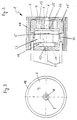
- a read head 1 is shown in axial section with its essential components.
- the reading head has an outer magnetically conductive housing pot 3, which is approximately U-shaped and has a reading opening 7 on the end face coaxial with its longitudinal center axis.
- the housing pot 3 On the side facing away from the end face 4, the housing pot 3 is closed off with a magnetically conductive base plate or a correspondingly conductive material.
- this reading head 1 has the field plate sensor 5, which is set back inwards from the end face.
- the field plate sensor 5 is magnetically connected to the reading opening via a mushroom-shaped guide pin 8.
- Field plate sensor 5 and guide pin 8 are arranged in the housing pot for precise alignment with the longitudinal axis of the reading head by means of a usually rotationally symmetrical centering body 15.
- a magnet in particular a permanent magnet 11, is provided, which has a magnetic connection between the bottom of the field plate sensor 5 and the bottom 12 of the housing pot 3.
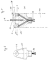
- FIG. 2 which shows a more precise structural design of a reading head 1 shown schematically in FIG. 1, it can be seen that the end face of the centering or guide pin 8 is flush with the end face 4 of the housing pot 3.
- the gap width can be adapted to the data carrier and the sensitivity required for error-free reading of the coding information.
- FIG. 1 shows that the T-, stamp-shaped or mushroom-shaped guide pin is designed concentrating or tapering in the direction of the reading opening, while being contacted on the field plate sensor in the manner of an attachment base 26 (FIG. 2).
- This contact base 26 ensures, so to speak, an expansion of the magnetic field lines so that they can be detected over the entire circumference of the field plate sensor 5.
- the centering body 15 is designed in Fig. 2 so that a potting of the components of the field plate sensor, the guide pin 8, the centering body 15 and the magnet 11 including a receiving body 23 for the field plate sensor 5 from the rear Side with potting compound 19 can follow. These components are aligned strictly axially symmetrically or coaxially to the longitudinal central axis.
- the centering body 15 advantageously has an insertion opening for the guide pin 8 and, viewed inwardly, a fitting opening for the field plate sensor 5.
- the centering body 15 is suitably aligned on the inner surfaces of the housing pot and has openings both in the end region in the direction of the reading opening 7 and in axially parallel fashion, so that the hardening and component-stabilizing casting compound can be introduced in one production step.
- the foremost area of the guide pin 8 towards the end face 4 is designed with its conical end, which is designed in the shape of a truncated cone.
- the magnetically insulating gap between the reading opening and the guide pin can also be changed very easily.
- all that would be required was a further bevel at the front end of the guide pin.
- a permanent magnet is arranged in the example with its north pole against the field plate sensor 5, while the south pole projects into the plate-like bottom end 12, which is magnetically conductive.
- electrical connections 22 are passed through this base plate 12.
- the housing pot 3 is provided with a casing 18, which generally ensures electrical shielding.
- FIG. 3 shows a view of the end face of the rotationally symmetrical read head 1, the same reference numerals of the figures relating to the same assemblies.
- FIG. 4 A basic illustration of the reading function is shown in FIG. 4.
- the reading head 1 is usually moved perpendicular to adjacent coding pins 9 by geometric design of the data carrier and the probe head having the reading head or a plurality of reading heads.
- the end face of the centering pin 8 is designed so that its diameter corresponds approximately to the width B of a coding pin 9, which consists of a magnetically conductive material, e.g. is designed as a soft magnet.
- the diameter of the reading opening 7 is designed to be somewhat larger than the width of a coding pin 9.
- the magnetic flux of the coding rod 9 that has just been scanned or read is guided into the guide pin 8, while interference fields from adjacent coding rods are passed through the end face 4 of the reading head 3 are magnetically short-circuited, so to speak.
- the reading head 1 can be considered to be rotationally symmetrical, so that a different angular inclination during scanning, which is indicated by an arrow P, has no influence on the information content.
- the interaction of two reading heads 1 aligned and opposed in the axis of symmetry S is shown in a probe 35 in a section along the central axis M.
- the reading heads 1 are spaced apart by a gap which corresponds to the width of a disk-like or disk-like data carrier 30 with a relatively precise fit.
- This data carrier 30 has on the left side a code track 37 and on the right side a clock track 36 in the form of coding rods 9. In the example, these coding sticks therefore lie parallel to the central axis M on or in the side surfaces of the data carrier 30.
- the spacing gap 38 between the two reading heads 1 is slightly offset to the right.
- the width perpendicular to the central axis M of the left area is somewhat larger than the width of the probe 35 in the right area. This ensures that an incorrect insertion of the probe when reading the data carrier 30 is impossible.
- the probe head is guided with a precise fit even in lateral guides, for example a number block according to DE 26 45 878 C2, so that there is only one alignment option between the probe head and the data carrier 30. This ensures that the left read head 1 always scans the code track, while the right read head alone reads the clock track 36.
- the reading heads 1 are received in the probe 35 in bores which are closed at the rear with a sealing compound 19 and an end plate 28.
- Corresponding lines 39 are made approximately in the area of the central axis M backwards in a handle 40 which receives the evaluation electronics.
- FIG. 6 shows a view to the side of the probe 35 according to FIG. 5.
- the probe is rounded in the front area, so that easy and safe movement along the data carrier is possible.
- the invention therefore permits reliable, error-free reading of the code information, interference from adjacent codes being avoided.
- Impairment due to abrasion on the field plate sensor is eliminated and, despite everything, optimum sensitivity is achieved by means of centering using a guide pin.
- the reading head is vibration-stable due to the potting compound used, and temperature changes and moisture do not have any noticeable effects on reading accuracy.
- a forward and backward movement of the stored information is therefore possible at any time with this design of the read head and the corresponding data carrier.
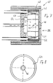
- the reading head 40 shown in FIG. 7 has a magnetically conductive housing pot 42, in the end face 44 of which faces the data carrier, a circular reading opening 46 is arranged.
- the reading opening 46 is tapered towards the end face 44 and is made of magnetically non-conductive material, e.g. Braze solder, filled out.
- the carrier 48 for the field plates 50 is separated from the reading opening 46 by a plastic film 52.
- the plastic film 52 is intended to dampen mechanical impacts on the end face 44 of the housing pot 42 and thus protect the field plates 50.
- the field plates 50 are connected to the housing pot 42 in a magnetically conductive manner via a permanent magnet 54 and the housing base 56. In this way a high output signal is obtained.
- the tapered design of the circular reading opening 46 achieves a sharp bundling of the magnetic flux, which enables a high resolution with regard to information contained on a data carrier, which is coded in the magnetic conductivity of the information carriers on the data carrier.
- Fig. 8 shows the top view of the end face 44 of the reading head 40 with the circular reading opening 46, which with Silver braze soldered.
- the conification of the reading opening 46 is realized by countersinking the end face 44 of the housing pot 42 from the rear of the housing pot.
Abstract
Description
Die Erfindung betrifft einen Lesekopf zum Lesen einer strich- oder stäbchenartigen, insbesondere passiv magnetischen Information auf einem Datenträger.The invention relates to a reading head for reading a line or stick-like, in particular passive magnetic information on a data carrier.
Ein Datenträger dieser Art ist beispielsweise in der DE 26 45 878 C2 beschrieben. Er weist beidseitig zwei Kodierungsspuren auf, von denen die eine die Informations- oder Codespur und die auf der anderen Seite gelegene die Synchronisations- oder Taktspur ist. Beide Spuren bestehen aus einzelnen länglichen Stäbchen, die voneinander etwa um den gleichen Abstand ihrer Breite angeordnet sind. Diese Stäbchen sind magnetisch leitend oder nichtleitend, so daß mit einem senkrecht zu den Stäbchen vorbeigeführten Lesekopf die darauf gespeicherte Information ausgelesen werden kann.A data carrier of this type is described for example in
Für die bekannten Leseköpfe werden Feldplatten-Sensoren verwendet. Um einerseits ein sicheres Abtasten und Auslesen der Information zu gewährleisten, wird der Lesekopf sehr nahe an den kodierten Stäbchen vorbeigeführt, was jedoch mit einem relativ hohen Verschleiß oder Verkratzen verbunden ist. Dieser Nachteil führt andererseits dazu, daß der Grundwiderstand der Feldplatten undefinierbare Werte annimmt, wodurch Fehlerablesungen die Folge sind.Field plate sensors are used for the known read heads. In order to ensure reliable scanning and reading of the information on the one hand, the reading head is moved very close to the coded rods, which, however, is associated with relatively high wear or scratching. On the other hand, this disadvantage leads to the basic resistance of the field plates assuming indefinable values, which results in error readings.
Weiterhin ist der physikalische und geometrische Aufbau des Lesekopfs noch so groß, daß bei einer leichten Schräghaltung des Lesekopfes im Vergleich zu der Ausrichtung der Kodierungsstäbchen der Feldplatten-Sensor zwei oder drei magnetische Kodierungen benachbarter Stäbchen erfaßt. Dies führt zu winkelabhängigen Auswertesignalen, da die Kodierung eines einzelnen Stäbchens nicht mehr mit Präzision erfaßt werden kann. Um derartige Fehler eliminieren zu können, bedarf es einer aufwendigen Auswerteschaltung, die sich jedoch für relativ einfache Massenprodukte verbietet.Furthermore, the physical and geometric structure of the read head is still so large that with a slight inclination of the read head compared to the alignment of the coding rods, the field plate sensor two or three magnetic encodings of adjacent rods detected. This leads to angle-dependent evaluation signals, since the coding of a single stick can no longer be detected with precision. In order to be able to eliminate such errors, a complex evaluation circuit is required, which is, however, forbidden for relatively simple mass products.
Aus der DE 27 05 439 C2 ist ein Lesekopf bekannt, der eine kreiszylindrische Leseöffnung aufweist und somit unanfällig ist gegen Winkelabweichungen vom Sollwinkel des Lesekopfes relativ zum Datenträger.From DE 27 05 439 C2 a reading head is known which has a circular cylindrical reading opening and is therefore not susceptible to angular deviations from the desired angle of the reading head relative to the data carrier.
Dieser Lesekopf ist in seiner Verwendung darin eingeschränkt, daß er sich nur zum Lesen aktiv magnetisierter Informationsträger eignet. Aktiv magnetisierte Informationsträger sind hingegen störungsanfällig gegen magnetische Störfelder. Diese können beim Informationsträger zum Verlust der gespeicherten Information führen.The use of this read head is restricted in that it is only suitable for reading actively magnetized information carriers. In contrast, actively magnetized information carriers are susceptible to interference from magnetic interference fields. These can lead to the loss of the stored information in the information carrier.
Der Erfindung liegt die Aufgabe zugrunde, einen gattungsgemäßen Lesekopf so zu verbessern, daß dieser eine gute Signalauswertung mit hoher Auflösung bei hoher Robustheit und winkelunabhängiger Führung gegenüber insbesondere passiv magnetisierten Kodierungsstäbchen erlaubt.The invention has for its object to improve a generic reading head so that it allows good signal evaluation with high resolution with high robustness and angle-independent guidance compared to passively magnetized coding rods.
Diese Aufgabe wird bei einem gattungsgemäßen Lesekopf erfindungsgemäß durch die Merkmale des Anspruchs 1 gelöst. Vorteilhafte Weiterbildungen sind Gegenstand der Unteransprüche.This object is achieved according to the invention in a generic read head by the features of
Der magnetische Fluß wird durch die erfindungsgemäße Ausbildung durch die Konifizierung der Leseöffnung stark gebündelt, wobei durch die magnetische Kopplung des Feldplattensensors über einen Dauermagneten mit dem Gehäusetopf ein relativ hohes Ausgangssignal erreicht wird. Der Lesekopf erlaubt das Lesen allein im magnetischen Widerstand enthaltener Information eines Datenträgers. Der Feldplatten-Sensor wird in einer Ausführungsform von der Stirnseite etwas zurückgesetzt, so daß er aus den Verschleißbereich herauskommt. Um jedoch eine hohe Empfindlichkeit im Hinblick auf Widerstandsänderungen in der Feldplatte zu erreichen, koppelt man zwischen der Leseöffnung, die sehr klein gehalten ist und nur etwas größer als die Breite eines Kodierungsstäbchens ist, einen magnetisch leitfähigen Leitstift, der sozusagen als Zentrierungs- oder Bündelungsstift angesehen werden kann. Mittels dieses Leitstifts wird die fiktive Umfangsfläche des Feldplatten-Sensor zur Stirnseite, also der Abtastseite hin, gebündelt und konzentriert. Die Sensorfläche wird daher zur Stirnseite hin sozusagen verkleinert, wobei jedoch hierdurch eine Anpassung an die Breite der Kodierungsstäbchen möglich ist. Ergänzend zu diesen Maßnahmen und der beabstandeten Anordnung des Feldplatten-Sensors gegenüber der Stirnfläche wird der gesamte Feldplatten-Sensor in einen magnetisch leitenden Gehäusetopf eingekapselt. Dieser Gehäusetopf läßt stirnseitig nur eine kleine Leseöffnung frei, in deren Mittelachse die Stirnfläche des Leitstifts zu liegen kommt.The magnetic flux is strongly concentrated by the configuration according to the invention through the conification of the reading opening, with the magnetic coupling of the field plate sensor via a permanent magnet to the housing pot a relatively high output signal is achieved. The reading head allows reading of a data carrier contained only in the magnetic resistance. In one embodiment, the field plate sensor is reset somewhat from the end face so that it comes out of the wear area. However, in order to achieve a high sensitivity with regard to changes in resistance in the field plate, a magnetically conductive guide pin, which is regarded as a centering or bundling pin, is coupled between the reading opening, which is kept very small and is only slightly larger than the width of a coding stick can be. By means of this guide pin, the fictitious peripheral surface of the field plate sensor is bundled and concentrated towards the front side, that is to say the scanning side. The sensor surface is therefore reduced, so to speak, towards the end face, but this allows adaptation to the width of the coding rods. In addition to these measures and the spaced arrangement of the field plate sensor opposite the end face, the entire field plate sensor is encapsulated in a magnetically conductive housing pot. This housing pot leaves only a small reading opening on the end face, in the central axis of which the end face of the guide pin comes to rest.
Der Abstand zwischen dem Leitstift und dem Randbereich der Leseöffnung im Gehäusetopf ist so gehalten, daß im Falle eines genau vor der Leseöffnung zu liegenden kommenden Kodierungsstifts eine erfaßbare Widerstandsänderung aufgrund des geänderten, magnetischen Flußes vor sich geht, wobei dies im Vergleich zum unterbrochenen magnetischen Fluß bei nicht vorhandenem Kodierungsstift zu sehen ist. Der Leitstift weist vorteilhafterweise etwa T-Form, Stempel- oder Pilzform auf, wobei in Richtung zur Leseöffnung gesehen eine allmähliche Verjüngung bevorzugt wird, die im Gehäusebereich kegelstumpfförmig zur Stirnfläche zuläuft. Auf der Seite des Feldplattensensor findet eine Verbreiterung statt, um mindestens die Gesamtfläche des Feldplatten-Sensors abzudecken. Auf der abgewandten Seite zur Leseöffnung ist der Feldplatten-Sensor magnetisch mit einem Magneten, speziell einem Dauermagneten, verbunden. Dieser Dauermagnet steht mit dem magnetisch leitfähigem Boden des Gehäusetopfes in Verbindung, so daß durch den geringen magnetischen Widerstand auch eine hohe Empfindlichkeit im Bereich der Leseöffnung erreicht wird. Aus fertigungstechnischen Gründen ist der Gehäusetopf im Schnitt etwa U-förmig und rotationssymmetrisch gehalten, wobei in der Symmetrieachse die Leseöffnung vorgesehen ist. Auf der abgewandten Seite zur Leseöffnung wird der Gehäusetopf mit einem magnetisch leitfähigen Boden bzw. einer Materialplatte abgeschlossen, so daß ein gekapseltes Gehäuse entsteht.The distance between the guide pin and the edge region of the reading opening in the housing pot is kept such that in the case of a coding pin coming exactly in front of the reading opening, a detectable change in resistance due to the changed magnetic flux takes place, this in comparison to the interrupted magnetic flux coding pin that is not present can be seen. The guide pin advantageously has a T-shape, stamp or mushroom shape, with a gradual tapering toward the reading opening being preferred, which tapers in the shape of a truncated cone to the end face in the housing area. On the A widening takes place on the side of the field plate sensor in order to cover at least the entire area of the field plate sensor. On the side facing away from the reading opening, the field plate sensor is magnetically connected to a magnet, especially a permanent magnet. This permanent magnet is connected to the magnetically conductive bottom of the housing pot, so that the low magnetic resistance also results in a high sensitivity in the area of the reading opening. For manufacturing reasons, the housing pot is held approximately U-shaped and rotationally symmetrical in section, the reading opening being provided in the axis of symmetry. On the side facing away from the reading opening, the housing pot is closed off with a magnetically conductive base or a material plate, so that an encapsulated housing is produced.
Im Hinblick auf eine hohe Empfindlichkeit wird der gesamte Lesekopf mit seinen Baugruppen über Zentriereinrichtungen auf die Längsmittelachse, die durch den Mittelpunkt der Leseöffnung geht, zentriert. Diese Zentrierung gilt vor allen Dingen für den Leitstift, den Feldplatten-Sensor und die Leseöffnung.With a view to high sensitivity, the entire reading head and its assemblies are centered on the longitudinal central axis, which passes through the center of the reading opening, via centering devices. This centering applies above all to the guide pin, the field plate sensor and the reading opening.
Die im Inneren des Gehäusetopfes angeordneten Einzelkomponenten des Lesekopfes sind so konstruiert, daß die Sensoreinheit problemlos mit einer Vergußmasse, die magnetisch nicht leitend ist, vergossen werden kann. Mit dieser Maßnahme erreicht man hohe Temperaturstabilität, wobei auch ein Schutz vor Feuchtigkeit und eine Vibrationsunempfindlichkeit erreicht werden.The individual components of the reading head arranged in the interior of the housing pot are constructed in such a way that the sensor unit can be cast with a potting compound that is not magnetically conductive without problems. With this measure, high temperature stability is achieved, protection against moisture and vibration insensitivity also being achieved.
Um den Lesekopf winkelunabhängig zu konzipieren, d.h. Einflüsse, die aus einer Schrägstellung der gesamten Abtasteinrichtung im Vergleich zur Senkrechtstellung gegenüber den Kodierungsstäbchen zu vermeiden, wird der Durchmesser der Leseöffnung im Vergleich zum stirnseitigen Durchmesser des Leitstifts so gehalten, daß der Durchmesser des Leitstifts etwa der Breite eines Kodierungsstifts entspricht und der Durchmesser der Leseöffnung nur geringfügig über diese Breite des Kodierungsstifts hinausragt. Hiermit wird gewährleistet, daß magnetische Einflüsse durch benachbarte Kodierungsstifte sozusagen in der Stirnfläche des Lesekopfes ausgeschlossen werden und keinen Einfluß auf die Abtastung des Zentrierstifts nehmen können. Der Lesekopf wird hiermit winkelunabhängig und sozusagen rotationssymmetrisch, so daß Fehlereinflüsse durch die den Lesekopf handhabende Person weitestgehend ausgeschlossen werden können.In order to design the read head independently of the angle, ie influences that arise from an inclined position of the entire scanning device compared to the vertical position To avoid the coding stick, the diameter of the reading opening is kept in comparison to the front diameter of the guide pin so that the diameter of the guide pin corresponds approximately to the width of a coding pin and the diameter of the reading opening protrudes only slightly beyond this width of the coding pin. This ensures that magnetic influences by adjacent coding pins are excluded, so to speak, in the end face of the reading head and cannot influence the scanning of the centering pin. The reading head is thus independent of the angle and, so to speak, rotationally symmetrical, so that the influence of errors by the person handling the reading head can be largely excluded.
Für die Auswertung der magnetischen Kodierung wird bei dieser Auslegung des Lesekopfes ein Kurvenverlauf der Widerstandsänderung im Feldplatten-Sensor erreicht, der nahezu optimal verläuft und dabei winkelunabhängig und zeitunkritisch ist. Besonders zweckmäßig ist eine dem Feldplatten-Sensor nachgeschaltete elektronische Schaltung, die einen rechteckigen Impuls pro magnetisch leitendem Stäbchen, vorzugsweise als "open collector"-Ausgang bereitstellt. Bei dieser Impulscharakteristik ist auch eine Umwandlung in ein digitales Ausgangssignal vereinfacht.For the evaluation of the magnetic coding, with this design of the reading head, a curve of the change in resistance in the field plate sensor is achieved, which runs almost optimally and is angle-independent and time-uncritical. An electronic circuit which is connected downstream of the field plate sensor and which provides a rectangular pulse per magnetically conductive rod, preferably as an "open collector" output, is particularly expedient. With this pulse characteristic, conversion into a digital output signal is also simplified.
Im Falle einer Code- und einer Synchronisationsspur ist es zweckmäßig, daß der mit zwei Leseköpfen ausgestattete Tastkopf im Hinblick auf die Zuordnung der Codespur zu einem bestimmten Lesekopf vertauschungssicher ausgelegt ist. Dies kann geeigneterweise mit einer unsymmetrischen Auslegung des Tastkopfes in Anpassung z.B. an unterschiedliche Breiten des Datenträgers oder Nummernblocks erfolgen, wie es die DE 26 45 878 C2 zeigt.In the case of a code track and a synchronization track, it is expedient that the probe head, which is equipped with two read heads, is designed to be non-interchangeable with regard to the assignment of the code track to a specific read head. This can be done suitably with an asymmetrical design of the probe head, for example to adapt to different widths of the data carrier or number block, as shown in
Im Hinblick auf die Auswertung der gelesenen Information ist es auch denkbar, daß die elektronische Auswertschaltung allein aufgrund der Sequenz der Information die Code- und Taktspur erkennt. Beispielsweise könnte die Codespur mit einem Kodierungsstift mehr ausgestattet sein, so daß in diesem Fall für die Taktspur magnetisch "0" gelesen wird.With regard to the evaluation of the information read, it is also conceivable that the electronic evaluation circuit recognizes the code and clock track solely on the basis of the sequence of the information. For example, the code track could be equipped with one more coding pin, so that in this case the clock track is read magnetically "0".
Trotz Rückversetzung des Feldplatten-Sensors in den Gehäusetopf hinein erscheint es zweckmäßig, den Innenwiderstand des Feldplatten-Sensors selbst mitzuüberwachen, um bei Erreichen z.B. eines kritischen Schwellwertes, der eine Fehlfunktion anzeigt, eine Sperrung des Lesekopfes visuell oder akustisch anzuzeigen, so daß die Funktionsunfähigkeit für den Benutzer erkennbar wird.Despite moving the field plate sensor back into the housing pot, it seems advisable to monitor the internal resistance of the field plate sensor yourself in order to e.g. a critical threshold value, which indicates a malfunction, to visually or acoustically indicate that the read head is locked, so that the inoperability can be recognized by the user.
Die Erfindung wird nachstehend schematisch anhand eines Ausführungsbeispiels noch näher erläutert. Es zeigen:
- Fig. 1
- einen Axialschnitt durch den schematischen Aufbau eines Lesekopfes mit Kodierungsstift im Bereich der Stirnseite;
- Fig. 2
- einen Schnitt vergleichbar zu Fig. 1, jedoch mit weiteren Details zu den Innenkomponenten des Lesekopfes;
- Fig. 3
- eine Ansicht auf die Stirnseite eines Lesekopfes nach Fig. 2;
- Fig. 4
- eine schematische Darstellung der Größenverhältnisse der Stirnseite des Lesekopfes und der Leseöffnung einschließlich Leitstift im Vergleich zu drei vorgesehenen Kodierungsstäbchen;
- Fig. 5
- eine Axialschnitt-Darstellung durch einen Tastkopf mit zwei einander zugewandten achssymmetrisch angeordneten Leseköpfen, zwischen denen ein plattenartiger Datenträger vorgesehen ist;
- Fig. 6
- eine Seitenansicht auf den Tastkopf nach Fig. 5 ohne Datenträger;
- Fig. 7
- einen Axialschnitt durch einen Lesekopf ohne Kodierungsstift und
- Fig. 8
- eine Aufsicht VIII auf die Stirnseite des Lesekopfes aus Fig. 7.
- Fig. 1
- an axial section through the schematic structure of a reading head with coding pin in the region of the front side;
- Fig. 2
- a section comparable to Figure 1, but with further details on the internal components of the reading head.
- Fig. 3
- a view of the end face of a read head of FIG. 2;
- Fig. 4
- a schematic representation of the proportions of the face of the reading head and the reading opening including guide pin compared to three provided coding rods;
- Fig. 5
- an axial section through a probe with two mutually axially symmetrically arranged read heads, between which a plate-like data carrier is provided;
- Fig. 6
- a side view of the probe of Figure 5 without a disk.
- Fig. 7
- an axial section through a read head without coding pin and
- Fig. 8
- a top view VIII of the face of the reading head from FIG. 7.
In Fig. 1 ist ein Lesekopf 1 im Axialschnitt mit seinen wesentlichen Komponenten dargestellt. Der Lesekopf weist einen äußeren magnetisch leitenden Gehäusetopf 3 auf, der in etwa U-Form hat und stirnseitig koaxial zu seiner Längsmittelachse eine Leseöffnung 7 aufweist. Auf der der Stirnseite 4 abgewandten Seite ist der Gehäusetopf 3 mit einer magnetisch leitenden Bodenplatte oder einem entsprechend leitfähigen Material abgeschlossen. Als innere Komponenten weist dieser Lesekopf 1 den von der Stirnseite nach innen zurückversetzten Feldplatten-Sensor 5 auf. Der Feldplatten-Sensor 5 steht mit der Leseöffnung über einen pilzförmigen Leitstift 8 magnetisch in Verbindung. Feldplatten-Sensor 5 und Leitstift 8 sind zur präzisen Ausrichtung auf die Längsachse des Lesekopfes mittels eines üblicherweise rotationssymmetrischen Zentrierkörpers 15 im Gehäusetopf angeordnet.In Fig. 1, a
Auf der Rückseite des Feldplatten-Sensors 5 ist ein Magnet, insbesondere ein Dauermagnet 11, vorgesehen, der einen magnetischen Schluß zwischen der Bodenseite des Feldplattensensors 5 und dem Boden 12 des Gehäusetopfes 3 herstellt. Unter Einbeziehung der Schnittdarstellung nach Fig. 2, die eine genauere konstruktive Auslegung eines in der Fig. 1 schematisch dargestellten Lesekopfes 1 zeigt, wird erkennbar, daß die Stirnfläche des Zentrier- bzw. Leitstifts 8 flächenbündig mit der Stirnseite 4 des Gehäusetopfes 3 abschließt. Bei einem koaxialen Aufbau, wie er dargestellt ist, besteht zwischen der Stirnseite des Leitstifts 8 und dem Rand der Leseöffnung ein relativ kleiner, magnetisch isolierender Spalt, der üblicherweise mit Vergußmasse 19 gefüllt ist. Die Spaltbreite ist unter anderem anpaßbar an den Datenträger und die Empfindlichkeit, die für ein fehlerfreies Auslesen der Kodierungsinformation erforderlich ist.On the back of the
Wie in Fig. 1 angedeutet, werden im dargestellten Fall, in dem sehr nahe an die Stirnfläche 4 des Lesekopfes 3 ein Kodierungsstäbchen 9 gelangt, die magnetischen Feldlinien 13 über dieses Kodierungsstäbchen 9 im Sinne einer Überbrükkung der Leseöffnung 7 zur Stirnseite des Leitstifts 8 geleitet. Der magnetische Widerstand des Gesamtkreises wird in diesem Fall wesentlich kleiner, so daß die Widerstandsänderung, die abhängig von der Magnetisierung unterschiedlicher Kodierungsstäbchen 9 ist, in einer nachgeschalteten (nicht gezeigten) elektronischen Schaltung als ausgelesene Information ausgewertet werden kann.As indicated in FIG. 1, in the case shown, in which a
Die schematische Darstellung nach Fig. 1 zeigt, daß der T-, stempel- bzw. pilzförmige Leitstift in Richtung zur Leseöffnung konzentrierend bzw. verjüngend ausgebildet ist, während er am Feldplatten-Sensor in Art eines Anbringungssockels 26 (Fig. 2) kontaktiert ist. Dieser Kontaktsockel 26 gewährleistet sozusagen eine Aufweitung der magnetischen Feldlinien, damit diese über den Gesamtumfang des Feldplatten Sensors 5 detektiert werden können.The schematic representation of FIG. 1 shows that the T-, stamp-shaped or mushroom-shaped guide pin is designed concentrating or tapering in the direction of the reading opening, while being contacted on the field plate sensor in the manner of an attachment base 26 (FIG. 2). This
Ergänzend zu Fig. 1 ist in Fig. 2 der Zentrierkörper 15 so gestaltet, daß ein Vergießen der Komponenten des Feldplatten-Sensors, des Leitstifts 8, des Zentrierkörpers 15 und des Magnets 11 einschließlich eines Aufnahmekörpers 23 für den Feldplatten-Sensor 5 von der rückwärtigen Seite her mit Vergußmasse 19 folgen kann. Die Ausrichtung dieser Komponenten erfolgt streng achssymmetrisch bzw. koaxial zur Längsmittelachse. Hierbei weist der Zentrierkörper 15 vorteilhafterweise eine Einführungsöffnung für den Leitstift 8 und nach innen gesehen eine Einpassungsöffnung für den Feldplatten-Sensor 5 auf. Der Zentrierkörper 15 wird dabei geeigneterweise an den Innenflächen des Gehäusetopfes ausgerichtet und weist sowohl im Stirnbereich in Richtung zur Leseöffnung 7 als auch achsparallel Durchbrechungen auf, so daß die erhärtende und komponentenstabilisierende Vergußmasse in einem Fertigungsschritt eingebracht werden kann.In addition to Fig. 1, the centering
Zur weiteren Verbesserung ist der vorderste Bereich des Leitstifts 8 zur Stirnseite 4 hin mit seinem konischen Ende, das kegelstumpfförmig gestaltet ist, ausgelegt. Über diese Konifizierung läßt sich auch der magnetisch isolierende Spalt zwischen Leseöffnung und Leitstift konstruktiv sehr einfach verändern. Es bedürfte hierzu bei gleicher Gehäusetopf-Geometrie lediglich einer weiteren Abschrägung am stirnseitigen Ende des Leitstifts.For further improvement, the foremost area of the
Am rückwärtigen Bereich des Feldplatten-Sensors 5 ist ein Dauermagnet im Beispiel mit seinem Nordpol gegen den Feldplatten-Sensor 5 angeordnet, während der Südpol in den plattenartigen Bodenabschluß 12 hineinragt, der magnetisch leitend ist. Selbstverständlich sind elektrische Anschlüsse 22 durch diese Bodenplatte 12 hindurchgeführt. An der radialen Umfangsseite ist z.B. der Gehäusetopf 3 mit einer Ummantelung 18 versehen, die in der Regel eine elektrische Abschirmung sicherstellt.At the rear of the
Die Darstellung in Fig. 3 zeigt eine Ansicht auf die Stirnfläche des rotationssymmetrisch aufgebauten Lesekopfes 1, wobei gleiche Bezugszeichen der Figuren gleiche Baugruppen betreffen.The illustration in FIG. 3 shows a view of the end face of the rotationally
Eine Prinzipdarstellung der Lesefunktion ist in Fig. 4 gezeigt. Der Lesekopf 1 wird üblicherweise senkrecht zu benachbarten Kodierungsstiften 9 durch geometrische Auslegung des Datenträgers und des den Lesekopf oder mehrere Leseköpfe aufweisenden Tastkopfes bewegt. Die stirnseitige Fläche des Zentrierstifts 8 wird so gestaltet, daß deren Durchmesser etwa der Breite B eines Kodierungsstifts 9 entspricht, der aus einem magnetisch leitfähigem Material besteht, z.B. als Weichmagnet ausgebildet ist.A basic illustration of the reading function is shown in FIG. 4. The reading
Der Durchmesser der Leseöffnung 7 ist dabei etwas größer ausgelegt als die Breite eines Kodierungsstifts 9. Auf diese Weise wird einerseits zentrierend der magnetische Fluß des gerade abgetasteten bzw. ausgelesenen Kodierungsstäbchens 9 in den Leitstift 8 geführt, während Störfelder benachbarter Kodierungsstäbchen durch die Stirnfläche 4 des Lesekopfes 3 sozusagen magnetisch kurzgeschlossen werden. Auf diese Weise kann der Lesekopf 1 als rotationssymmetrisch ausgebildet angesehen werden, so daß auch eine unterschiedliche Winkelneigung beim Abtasten, die durch einen Pfeil P angedeutet ist, keinen Einfluß auf den Informationsgehalt hat.The diameter of the
In der Darstellung nach Fig. 5 ist das Zusammenwirken zweier in der Symmetrieachse S ausgerichteter und gegenüberliegender Leseköpfe 1 in einem Tastkopf 35 in einem Schnitt längs der Mittelachse M dargestellt. Die Leseköpfe 1 sind dabei über einen Spalt beabstandet, der relativ paßgenau der Breite eines scheiben- oder plättchenartigen Datenträgers 30 entspricht. Dieser Datenträger 30 weist auf der linken Seite eine Codespur 37 und auf der rechten Seite eine Taktspur 36 in Form von Kodierungsstäbchen 9 auf. Diese Kodierungsstäbchen liegen daher im Beispiel parallel zur Mittelachse M auf bzw. in den Seitenflächen des Datenträgers 30. Der Abstandsspalt 38 zwischen den beiden Leseköpfen 1 ist geringfügig nach rechts versetzt. Mit anderen Worten ist die Breite senkrecht zur Mittelachse M des linken Bereichs etwas größer als die Breite des Tastkopfes 35 im rechten Bereich. Hiermit wird sichergestellt, daß ein falsches Einführen des Tastkopfes beim Ablesen des Datenträgers 30 unmöglich wird. In diesem Zusammenhang sei erwähnt, daß der Tastkopf selbst in seitlichen Führungen z.B. eines Nummernblocks gemäß der DE 26 45 878 C2 paßgenau geführt wird, so daß nur eine Ausrichtungsmöglichkeit zwischen Tastkopf und dem Datenträger 30 besteht. Hiermit ist gewährleistet, daß der linke Lesekopf 1 stets die Codespur abtastet, während der rechte Lesekopf allein die Taktspur 36 ausliest.In the illustration according to FIG. 5, the interaction of two
Die Leseköpfe 1 sind im Beispiel nach Fig. 5 im Tastkopf 35 in Bohrungen aufgenommen, die rückwärtig mit einer Vergußmasse 19 und einer Abschlußplatte 28 geschlossen sind. Entsprechende Leitungen 39 sind etwa im Bereich der Mittelachse M nach rückwärts in einen Handgriff 40 ausgeführt, der die Auswerteelektronik aufnimmt.In the example according to FIG. 5, the reading heads 1 are received in the
In Fig. 6 ist eine Ansicht auf die Seite des Tastkopfes 35 nach Fig. 5 gezeigt. Der Tastkopf ist im vorderen Bereich abgerundet gestaltet, so daß ein leichtes und sicheres Bewegen längs des Datenträgers möglich ist.FIG. 6 shows a view to the side of the
Die Erfindung gestattet daher ein sicheres, fehlerfreies Auslesen der Codeinformation, wobei Störeinflüsse durch benachbarte Kodierungen vermieden werden. Zudem wird die Beeinträchtigung durch Abrieb an dem Feldplatten-Sensor eliminiert und trotz allem eine optimale Empfindlichkeit durch die Zentrierungsmöglichkeit mittels eines Leitstifts erreicht. Der Lesekopf ist durch die eingesetzte Vergußmasse vibrationsstabil, wobei auch Temperaturänderungen und Feuchtigkeit keine merklichen Einflüsse auf die Lesegenauigkeit mit sich bringen.The invention therefore permits reliable, error-free reading of the code information, interference from adjacent codes being avoided. In addition, the Impairment due to abrasion on the field plate sensor is eliminated and, despite everything, optimum sensitivity is achieved by means of centering using a guide pin. The reading head is vibration-stable due to the potting compound used, and temperature changes and moisture do not have any noticeable effects on reading accuracy.
Eine Vorwärts- wie Rückwärtsbewegung der gespeicherten Information ist daher bei dieser Auslegung des Lesekopfes und des entsprechenden Datenträgers jederzeit möglich.A forward and backward movement of the stored information is therefore possible at any time with this design of the read head and the corresponding data carrier.
Der in Fig. 7 dargestellte Lesekopf 40 hat einen magnetisch leitenden Gehäusetopf 42, in dessen dem Datenträger zugewandten Stirnseite 44 eine kreisrunde Leseöffnung 46 angeordnet ist. Die Leseöffnung 46 ist konisch zur Stirnseite 44 zulaufend und ist mit magnetisch nicht leitfähigem Material, z.B. Hartlot, ausgefüllt. Der Träger 48 für die Feldplatten 50 ist durch eine Kunststoffolie 52 von der Leseöffnung 46 getrennt. Die Kunststoffolie 52 soll mechanische Schläge auf die Stirnseite 44 des Gehäusetopfes 42 abdämpfen und damit die Feldplatten 50 schonen. Die Feldplatten 50 sind über einen Dauermagneten 54 und dem Gehäuseboden 56 mit dem Gehäusetopf 42 magnetisch leitend verbunden. Auf diese Weise wird ein hohes Ausgangssignal erhalten. Durch die konifizierte Ausbildung der zirkularen Leseöffnung 46 wird eine scharfe Bündelung des Magnetflusses erreicht, der eine hohe Auflösung bezüglich einer auf einem Datenträger enthaltenen Information ermöglicht, die in der magnetischen Leitfähigkeit der Informationsträger auf dem Datenträger kodiert ist.The reading
Fig. 8 zeigt die Aufsicht auf die Stirnseite 44 des Lesekopfes 40 mit der kreisrunden Leseöffnung 46, die mit Silberhartlot zugelötet ist. Die Konifizierung der Leseöffnung 46 wird durch eine Ansenkung der Stirnseite 44 des Gehäusetopfes 42 von der Rückseite des Gehäusetopfes her realisiert.Fig. 8 shows the top view of the
Claims (17)
dadurch gekennzeichnet,
daß die Leseöffnung zur Stirnseite des Lesekopfes hin konifiziert ist,
daß der Lesekopf in einem Gehäusetopf angeordnet ist und mindestens einen Feldplattensensor aufweist und daß ein Dauermagnet stirnseitenabgewandt am Feldplattensensor mit magnetischem Schluß zum Gehäusetopf angeordnet ist.Reading head for reading a line-like or rod-like, in particular passive magnetic information on a data carrier, with a reading opening,
characterized by
that the reading opening is butted towards the front of the reading head,
that the reading head is arranged in a housing pot and has at least one field plate sensor and that a permanent magnet is arranged on the field plate sensor facing away from the end face with a magnetic connection to the housing pot.
bei dem in die Leseöffnung stirnseitig ein magnetisch leitfähiger Leitstift ragt,
dadurch gekennzeichnet,
daß der Leitstift zum Gehäusetopf magnetisch isoliert und stirnseitenabgewandt flächig mit dem Feldplattensensor kontaktiert ist.Read head according to claim 1,
in which a magnetically conductive guide pin protrudes into the front of the reading opening,
characterized by
that the guide pin to the housing pot is magnetically insulated and is face-to-face contact with the field plate sensor.
dadurch gekennzeichnet,
daß der Leitstift und der Feldplattensensor eine dem Datenträger zugewandte stirnseitige Fläche haben, wobei die stirnseitige Fläche des Leitstifts kleiner ist als die stirnseitige Fläche des Feldplattensensors.Read head according to claim 2,
characterized by
that the guide pin and the field plate sensor have an end face facing the data carrier, the front face of the guide pin being smaller than the end face of the field plate sensor.
dadurch gekennzeichnet,
daß der Leitstift T-förmig, pilz- oder stempelförmig gestaltet ist.Read head according to claim 2 or 3,
characterized by
that the guide pin is T-shaped, mushroom-shaped or stamp-shaped.
dadurch gekennzeichnet,
daß der Leitstift eine stirnseitige Fläche hat, deren Durchmesser in etwa der Breite der strich- oder stäbchenartigen magnetischen Information auf dem Datenträger entspricht.Read head according to one of the preceding claims,
characterized by
that the guide pin has an end face whose diameter corresponds approximately to the width of the line-like or rod-like magnetic information on the data carrier.
dadurch gekennzeichnet,
daß der Gehäusetopf magnetisch gekapselt den Feldplatten-Sensor aufnimmt und daß der Durchmesser der stirnseitigen Leseöffnung geringfügig größer als der Durchmesser des Leitstifts ist.Read head according to one of the preceding claims,
characterized by
that the housing pot magnetically encapsulates the field plate sensor and that the diameter of the front reading opening is slightly larger than the diameter of the guide pin.
dadurch gekennzeichnet,
daß der Gehäusetopf magnetisch gekapselt den Feldplatten-Sensor aufnimmt und daß die Breite der stirnseitigen Leseöffnung geringfügig größer als die stirnseitige Breite des Leitstifts ist.Read head according to one of the preceding claims,
characterized by
that the housing pot magnetically encapsulated receives the field plate sensor and that the width of the front reading opening is slightly larger than the front width of the guide pin.
dadurch gekennzeichnet,
daß der Leitstift im Bereich der Leseöffnung in Richtung zur Stirnseite, insbesondere kegelstumpfartig, verjüngt ausgebildet ist.Read head according to one of the preceding claims,
characterized by t,
that the guide pin is tapered in the region of the reading opening in the direction of the end face, in particular frustoconical.
dadurch gekennzeichnet,
daß der Gehäusetopf im Schnitt U-förmig ist und eine Vorderfläche aufweist, die eine plane Stirnseite mit der Leseöffnung bildet und daß stirnseitenabgewandt ein magnetisch leitfähiges Material in Kontakt mit dem Dauermagneten und dem Gehäusetopf vorgesehen ist.Read head according to one of the preceding claims,
characterized by
that the housing pot is U-shaped in section and has a front surface which forms a flat end face with the reading opening and that, facing away from the end face, a magnetically conductive material is provided in contact with the permanent magnet and the housing pot.
dadurch gekennzeichnet,
daß Gehäusetopf, Leitstift und Dauermagnet koaxial zur Mittelachse des Feldplatten-Sensors angeordnet sind.Read head according to one of the preceding claims,
characterized by
that the housing pot, guide pin and permanent magnet are arranged coaxially to the central axis of the field plate sensor.
dadurch gekennzeichnet,
daß der Feldplatten-Sensor im Gehäusetopf mittels einer Zentrier-Einrichtung koaxial angeordnet und mit einer magnetisch isolierenden Vergußmasse vergossen ist.Read head according to one of the preceding claims,
characterized by
that the field plate sensor is arranged coaxially in the housing pot by means of a centering device and is potted with a magnetically insulating potting compound.
für einen scheiben- oder stegartigen Datenträger mit zweiseitiger magnetischer Information,
dadurch gekennzeichnet,
daß zwei stirnseitig zugewandte Gehäusetöpfe mit achssymmetrischer Ausrichtung ihrer Leseöffnungen in einem Abstand von der Breite des Datenträgers vorgesehen sind.Read head according to one of the preceding claims,
for a disk-like or web-like data carrier with double-sided magnetic information,
characterized by
that two front-facing housing pots are provided with axially symmetrical alignment of their reading openings at a distance from the width of the data carrier.
dadurch gekennzeichnet,
daß der Leitstift fixiert ist, und daß die Relativbewegung zwischen strich- oder stäbchenartiger magnetischer Information auf dem Datenträger und dem fixierten Leitstift im wesentlichen senkrecht zu benachbarten Strich- oder Stächencodierungen erfolgt.Read head according to one of the preceding claims,
characterized by
that the guide pin is fixed, and that the relative movement between line-like or rod-like magnetic information on the data carrier and the fixed guide pin is essentially perpendicular to adjacent bar or field codes.
dadurch gekennzeichnet,
daß der Leitstift eine stirnseitige Fläche hat, die winkelunabhängig in Relation zur magnetischen Information auf dem Datenträger ausgelegt ist.Read head according to one of the preceding claims,
characterized by
that the guide pin has an end face that is designed independent of the angle in relation to the magnetic information on the data carrier.
dadurch gekennzeichnet,
daß die Leseöffnung mit magnetisch nicht leitfähigem Material verschlossen ist.Read head according to claim 1,
characterized by
that the reading opening is closed with magnetically non-conductive material.
dadurch gekennzeichnet,
daß die Leseöffnung mit Hartlot verschlossen ist.Read head according to claim 15,
characterized by t,
that the reading opening is closed with hard solder.
dadurch gekennzeichnet,
daß zwischen den Feldplatten und der Leseöffnung eine Schicht zur mechanischen Dämpfung, insbesondere eine Kunststoffolie angeordnet ist.Read head according to claim 16,
characterized by
that a layer for mechanical damping, in particular a plastic film, is arranged between the field plates and the reading opening.
Applications Claiming Priority (2)
| Application Number | Priority Date | Filing Date | Title |
|---|---|---|---|
| DE4021241 | 1990-07-04 | ||
| DE4021241A DE4021241A1 (en) | 1990-07-04 | 1990-07-04 | READING HEAD |
Publications (3)
| Publication Number | Publication Date |
|---|---|
| EP0464685A2 true EP0464685A2 (en) | 1992-01-08 |
| EP0464685A3 EP0464685A3 (en) | 1992-12-16 |
| EP0464685B1 EP0464685B1 (en) | 1995-02-22 |
Family
ID=6409611
Family Applications (1)
| Application Number | Title | Priority Date | Filing Date |
|---|---|---|---|
| EP91110682A Expired - Lifetime EP0464685B1 (en) | 1990-07-04 | 1991-06-27 | Reading head |
Country Status (5)
| Country | Link |
|---|---|
| US (1) | US5258603A (en) |
| EP (1) | EP0464685B1 (en) |
| AT (1) | ATE118910T1 (en) |
| CA (1) | CA2046151A1 (en) |
| DE (2) | DE4021241A1 (en) |
Families Citing this family (2)
| Publication number | Priority date | Publication date | Assignee | Title |
|---|---|---|---|---|
| DE19519480C2 (en) * | 1995-05-27 | 2000-02-03 | Forschungszentrum Juelich Gmbh | Magnetic flux sensor with high spatial resolution |
| US5997582A (en) * | 1998-05-01 | 1999-12-07 | Weiss; James M. | Hip replacement methods and apparatus |
Citations (2)
| Publication number | Priority date | Publication date | Assignee | Title |
|---|---|---|---|---|
| DE2705439A1 (en) * | 1976-02-10 | 1977-08-11 | Denki Onkyo Co Ltd | MAGNETIC SENSOR |
| US4141494A (en) * | 1977-02-25 | 1979-02-27 | Fisher Alan J | Digital code reader |
Family Cites Families (6)
| Publication number | Priority date | Publication date | Assignee | Title |
|---|---|---|---|---|
| US3710362A (en) * | 1971-09-13 | 1973-01-09 | A Kronfeld | Hand held transducer insensitive to angular orientation |
| US3723669A (en) * | 1971-12-16 | 1973-03-27 | Singer Co | Hand held magnetic reader |
| DE2604645A1 (en) * | 1976-02-06 | 1977-08-11 | Ultrakust Geraetebau | DEVICE FOR RECORDING IDENTIFICATION NUMBERS WHEN ACCEPTING MILK BY TANK COLLECTOR |
| US4291351A (en) * | 1979-11-28 | 1981-09-22 | International Business Machines Corporation | Flux extender or guide for magnetic read head having a magnetoresistive flux sensor |
| JPS56168282A (en) * | 1980-05-28 | 1981-12-24 | Denki Onkyo Co Ltd | Magnetic sensor device |
| JPH02124575U (en) * | 1989-03-24 | 1990-10-15 |
-
1990
- 1990-07-04 DE DE4021241A patent/DE4021241A1/en active Granted
-
1991
- 1991-06-27 EP EP91110682A patent/EP0464685B1/en not_active Expired - Lifetime
- 1991-06-27 DE DE59104660T patent/DE59104660D1/en not_active Expired - Fee Related
- 1991-06-27 AT AT91110682T patent/ATE118910T1/en not_active IP Right Cessation
- 1991-07-03 CA CA002046151A patent/CA2046151A1/en not_active Abandoned
- 1991-07-05 US US07/726,190 patent/US5258603A/en not_active Expired - Fee Related
Patent Citations (2)
| Publication number | Priority date | Publication date | Assignee | Title |
|---|---|---|---|---|
| DE2705439A1 (en) * | 1976-02-10 | 1977-08-11 | Denki Onkyo Co Ltd | MAGNETIC SENSOR |
| US4141494A (en) * | 1977-02-25 | 1979-02-27 | Fisher Alan J | Digital code reader |
Non-Patent Citations (1)
| Title |
|---|
| IBM TECHNICAL DISCLOSURE BULLETIN, Band 22, Nr. 8B, Januar 1980, Seite 3678, New York, US; G.F. PENNELL et al.: "Circular face flux extender" * |
Also Published As
| Publication number | Publication date |
|---|---|
| DE4021241A1 (en) | 1992-01-16 |
| EP0464685A3 (en) | 1992-12-16 |
| EP0464685B1 (en) | 1995-02-22 |
| US5258603A (en) | 1993-11-02 |
| CA2046151A1 (en) | 1992-01-05 |
| ATE118910T1 (en) | 1995-03-15 |
| DE59104660D1 (en) | 1995-03-30 |
| DE4021241C2 (en) | 1993-06-24 |
Similar Documents
| Publication | Publication Date | Title |
|---|---|---|
| DE2621790C2 (en) | ||
| DE2933557C2 (en) | Transmitter for non-contact distance or speed measurement | |
| AT392549B (en) | MAGNETIC TAPE WITH A MAGNETIC HEAD | |
| DE10330986B4 (en) | Non-contact scanning with magnetoresistive sensor | |
| DE2558956C2 (en) | ||
| DE3819783C2 (en) | ||
| DE19507304B4 (en) | magnetic field detector | |
| DE2841424B2 (en) | ||
| DE2453540C2 (en) | Magnetoresistive component | |
| DE3800824A1 (en) | DEVICE WITH AT LEAST ONE MAGNETIC FIELD DEPENDENT IN A HOUSING | |
| DE2027760C3 (en) | Clock generator arrangement for rotating magnetic storage | |
| DE3137951C2 (en) | Hydraulic push-piston gear, in particular for use as a back and forth cylinder in underground mining operations, with permanent magnets arranged on the piston rod | |
| DE3824045C2 (en) | Magnetic head assembly for a magnetic tape device | |
| EP0598934B1 (en) | Measuring device for the contactless determination of the rotational speed, respectively speed or position, of an object | |
| EP0464685B1 (en) | Reading head | |
| DE3008581C2 (en) | ||
| EP0266585A1 (en) | Rotation speed measuring apparatus with a magnetoresistive sensor, especially for anti-skid systems for vehicles | |
| DE3916978C2 (en) | ||
| DE2521163C2 (en) | DEVICE FOR DETERMINING A SIZE CORRESPONDING TO THE SPEED OR THE ROTATION ANGLE OF AN AXIS | |
| DE3637320C2 (en) | ||
| EP0144601A1 (en) | Read head for magnetically sensing Wiegand wires | |
| DE10013525C2 (en) | Device for the wireless transmission of sensor position signals to an elongated RF coil | |
| DE1146540B (en) | Multi-track magnetic head | |
| EP1656537B1 (en) | Position sensor | |
| DE2853813A1 (en) | Electricity meter pulse generator - controls tariff unit or remote reading and uses magnetic transmitter, rotating with meter disc, and fixed receiver |
Legal Events
| Date | Code | Title | Description |
|---|---|---|---|
| PUAI | Public reference made under article 153(3) epc to a published international application that has entered the european phase |
Free format text: ORIGINAL CODE: 0009012 |
|
| AK | Designated contracting states |
Kind code of ref document: A2 Designated state(s): AT BE CH DE DK ES FR GB GR IT LI LU NL SE |
|
| PUAL | Search report despatched |
Free format text: ORIGINAL CODE: 0009013 |
|
| AK | Designated contracting states |
Kind code of ref document: A3 Designated state(s): AT BE CH DE DK ES FR GB GR IT LI LU NL SE |
|
| 17P | Request for examination filed |
Effective date: 19921214 |
|
| RAP1 | Party data changed (applicant data changed or rights of an application transferred) |
Owner name: ULTRAKUST ELECTRONIC GMBH |
|
| 17Q | First examination report despatched |
Effective date: 19940803 |
|
| GRAA | (expected) grant |
Free format text: ORIGINAL CODE: 0009210 |
|
| AK | Designated contracting states |
Kind code of ref document: B1 Designated state(s): AT BE CH DE DK ES FR GB GR IT LI LU NL SE |
|
| PG25 | Lapsed in a contracting state [announced via postgrant information from national office to epo] |
Ref country code: GR Free format text: LAPSE BECAUSE OF FAILURE TO SUBMIT A TRANSLATION OF THE DESCRIPTION OR TO PAY THE FEE WITHIN THE PRESCRIBED TIME-LIMIT Effective date: 19950222 Ref country code: GB Effective date: 19950222 Ref country code: NL Free format text: LAPSE BECAUSE OF NON-PAYMENT OF DUE FEES Effective date: 19950222 Ref country code: FR Effective date: 19950222 Ref country code: ES Free format text: THE PATENT HAS BEEN ANNULLED BY A DECISION OF A NATIONAL AUTHORITY Effective date: 19950222 Ref country code: BE Effective date: 19950222 Ref country code: DK Effective date: 19950222 Ref country code: IT Free format text: LAPSE BECAUSE OF FAILURE TO SUBMIT A TRANSLATION OF THE DESCRIPTION OR TO PAY THE FEE WITHIN THE PRESCRIBED TIME-LIMIT;WARNING: LAPSES OF ITALIAN PATENTS WITH EFFECTIVE DATE BEFORE 2007 MAY HAVE OCCURRED AT ANY TIME BEFORE 2007. THE CORRECT EFFECTIVE DATE MAY BE DIFFERENT FROM THE ONE RECORDED. Effective date: 19950222 |
|
| REF | Corresponds to: |
Ref document number: 118910 Country of ref document: AT Date of ref document: 19950315 Kind code of ref document: T |
|
| REF | Corresponds to: |
Ref document number: 59104660 Country of ref document: DE Date of ref document: 19950330 |
|
| PG25 | Lapsed in a contracting state [announced via postgrant information from national office to epo] |
Ref country code: SE Effective date: 19950522 |
|
| PG25 | Lapsed in a contracting state [announced via postgrant information from national office to epo] |
Ref country code: AT Effective date: 19950627 |
|
| PG25 | Lapsed in a contracting state [announced via postgrant information from national office to epo] |
Ref country code: LU Free format text: LAPSE BECAUSE OF NON-PAYMENT OF DUE FEES Effective date: 19950630 Ref country code: CH Effective date: 19950630 Ref country code: LI Effective date: 19950630 |
|
| EN | Fr: translation not filed | ||
| GBV | Gb: ep patent (uk) treated as always having been void in accordance with gb section 77(7)/1977 [no translation filed] |
Effective date: 19950222 |
|
| NLV1 | Nl: lapsed or annulled due to failure to fulfill the requirements of art. 29p and 29m of the patents act | ||
| PLBE | No opposition filed within time limit |
Free format text: ORIGINAL CODE: 0009261 |
|
| STAA | Information on the status of an ep patent application or granted ep patent |
Free format text: STATUS: NO OPPOSITION FILED WITHIN TIME LIMIT |
|
| 26N | No opposition filed | ||
| REG | Reference to a national code |
Ref country code: CH Ref legal event code: PL |
|
| PGFP | Annual fee paid to national office [announced via postgrant information from national office to epo] |
Ref country code: DE Payment date: 20000523 Year of fee payment: 10 |
|
| PG25 | Lapsed in a contracting state [announced via postgrant information from national office to epo] |
Ref country code: DE Free format text: LAPSE BECAUSE OF NON-PAYMENT OF DUE FEES Effective date: 20020403 |