EP0464551A2 - Method and apparatus for controlling drives coupled to a computer system - Google Patents
Method and apparatus for controlling drives coupled to a computer system Download PDFInfo
- Publication number
- EP0464551A2 EP0464551A2 EP91110366A EP91110366A EP0464551A2 EP 0464551 A2 EP0464551 A2 EP 0464551A2 EP 91110366 A EP91110366 A EP 91110366A EP 91110366 A EP91110366 A EP 91110366A EP 0464551 A2 EP0464551 A2 EP 0464551A2
- Authority
- EP
- European Patent Office
- Prior art keywords
- hard disk
- disk drive
- drive
- coupled
- pop
- Prior art date
- Legal status (The legal status is an assumption and is not a legal conclusion. Google has not performed a legal analysis and makes no representation as to the accuracy of the status listed.)
- Withdrawn
Links
Images


Classifications
-
- G—PHYSICS
- G06—COMPUTING; CALCULATING OR COUNTING
- G06F—ELECTRIC DIGITAL DATA PROCESSING
- G06F3/00—Input arrangements for transferring data to be processed into a form capable of being handled by the computer; Output arrangements for transferring data from processing unit to output unit, e.g. interface arrangements
- G06F3/06—Digital input from, or digital output to, record carriers, e.g. RAID, emulated record carriers or networked record carriers
- G06F3/0601—Interfaces specially adapted for storage systems
-
- G—PHYSICS
- G06—COMPUTING; CALCULATING OR COUNTING
- G06F—ELECTRIC DIGITAL DATA PROCESSING
- G06F13/00—Interconnection of, or transfer of information or other signals between, memories, input/output devices or central processing units
- G06F13/14—Handling requests for interconnection or transfer
- G06F13/36—Handling requests for interconnection or transfer for access to common bus or bus system
-
- G—PHYSICS
- G06—COMPUTING; CALCULATING OR COUNTING
- G06F—ELECTRIC DIGITAL DATA PROCESSING
- G06F3/00—Input arrangements for transferring data to be processed into a form capable of being handled by the computer; Output arrangements for transferring data from processing unit to output unit, e.g. interface arrangements
- G06F3/06—Digital input from, or digital output to, record carriers, e.g. RAID, emulated record carriers or networked record carriers
- G06F3/0601—Interfaces specially adapted for storage systems
- G06F3/0668—Interfaces specially adapted for storage systems adopting a particular infrastructure
- G06F3/0671—In-line storage system
- G06F3/0673—Single storage device
Definitions
- the present invention relates to a method and an apparatus for controlling drives coupled to a computer system.
- Various portable lap-top type personal computers which can be driven by batteries have recently been developed. These personal computers each include a magnetic recording device such as a floppy disk drive and a hard disk drive.
- a magnetic recording device such as a floppy disk drive and a hard disk drive is externally set. Since, therefore, the externally-set magnetic recording device needs to be coupled to the body of the personal computer, the characteristics of the lap-top type computer, such as miniaturization, lightness and portability are lost. Since a connecter and a cable are used to couple the externally-set magnetic recording device to the body of the personal computer, the manufacturing cost of the computer increases and the reliability thereof decreases.
- the hard disk drive In a conventional computer including a hard disk drive, the hard disk drive is inherent in the computer and fixed therein. Information stored in the hard disk drive cannot be utilized directly by another computer.
- an externally-set hard disk drive When an externally-set hard disk drive is coupled to the body of a computer, it cannot be access-controlled when necessary since there is neither a device capable of accessing the externally-set hard disk drive in place of an internally-set hard disk drive nor a device capable of accessing the externally-set hard disk drive in addition to the internally-set hard disk drive.
- a computer system comprising: a computer body; at least one hard disk drive to be coupled to the computer body, a hard disk drive to be externally coupled to the computer body and having a switch for designating a drive number; and determination and set means for determining whether or not the drive number designated by the switch is a first drive number when the hard disk drive is externally coupled to the computer body, determining whether or not the hard disk drive is externally coupled to the computer body when the hard disk drive is internally coupled to the computer body, and setting the drive number to the coupled hard disk drive in accordance with determination results to obtain memory address regions of the coupled hard disk drive.
- a computer system comprising: a computer body having a computer memory for storing normal pop-up menu data; at least one hard disk drive to be coupled to the computer body and having a drive memory for storing drive pop-up menu data for the hard disk drive; means for determining whether or not the hard disk drive is coupled to the computer body, reading out the drive pop-up menu data from the drive memory of the coupled hard disk drive when the hard disk drive is coupled to the computer body, reading out the normal pop-up menu data from the computer memory, and adding the drive pop-up menu data to the normal pop-up menu data to obtain added pop-up menu data when the hard disk drive is coupled to the computer body: and display means for displaying a pop-up menu using one of the normal pop-up menu data and the added pop-up menu data in accordance with a determination result.
- Fig. 1 is a block diagram showing a configuration of a computer system according to an embodiment of the present invention.
- Fig. 2 is a view showing main components of the computer system.
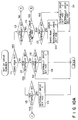
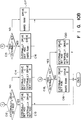
- the computer system shown in Fig. 1 comprises a system bus 10, a central processing unit (CPU) 11 for controlling the entire computer system, a read only memory (ROM) 12 for storing control programs for the computer system, pop-up menu data, and the like, a random access memory (RAM) 13 for storing data to be processed, a direct memory access controller (DMAC) 14 for direct memory access control, a programmable interrupt controller (PIC) 15 which can be set by programs, a programmable interval timer (PIT) 16 which can be set by programs, a real time clock (RTC) 17 used as a timer module having a driving battery 17a, a large-capacity extended RAM 18 connectable to a card slot 18a, and a backup RAM 19 for storing data or the like to execute a resume process.
- CPU central processing unit
- ROM read only memory
- RAM random access memory
- DMAC direct memory access controller
- PIC programmable interrupt controller
- PIT programmable interval timer
- RTC real time clock
- the computer system also comprises a floppy disk controller (FDC) 20.
- Floppy disk drives 32A and 32B are connected to the FDC 20 by connecters 61 and 60, respectively and controlled by the FDC 20.
- a hard disk drive of, for example, 2.5 inches can be coupled to the computer system of the present invention. Accordingly, the computer system can be easily advanced. The method of coupling the hard disk drive to the computer system will be described later.
- the computer system further comprises a printer controller (PRT-CONT) 21, a universal asynchronous receiver/transmitter (UART) 22 used as an input and output interface, a keyboard controller (KBC) 23, a display controller (DISP-CONT) 24, a video RAM (VRAM) 25, a kanji ROM 26, a dictionary ROM 27, a power supply interface (PS-IF) 28, an alternating current (AC) adapter 29, a power supply circuit 30 having a power control CPU (PC-CPU) 30a, main batteries (M-BAT) 31A and 31B, a sub-battery (S-BAT) 31C, a keyboard 36, a liquid crystal display (LCD) 37, and power switch 45.
- PRT-CONT printer controller
- UART universal asynchronous receiver/transmitter
- KBC keyboard controller
- DISP-CONT display controller
- VRAM video RAM
- PS-IF power supply interface
- AC alternating current
- PC-CPU power control CPU
- main batteries M-BAT
- a 5-inch externally-set floppy disk drive 33 and a printer 34 are selectively coupled to the PRT-CONT 21 by a connector.
- An RS-232C interface unit 35 is connected to the UART 22, if necessary.
- the KBC 23 controls a key input from the keyboard 36 arranged on the body of the computer system.
- the DISP-CONT 24 controls the swingable LCD 37 attached to the body of the computer system, or a cathode ray tube (CRT) display 38 selectively connected to the DISP-CONT 24.
- a backup voltage V BK is applied to the VRAM 25.
- the kanji ROM 26 is used to convert a kanji character code into a kanji character pattern.
- the dictionary ROM 27 is used to perform kana-to-kanji conversion.
- the PS-IF 28 executes serial data transmission to the PC-CPU 30a of the power supply circuit 30.
- the AC adapter 29 rectifies and smooths an AC voltage from an externally-set power supply and then supplies a predetermined direct current (DC) voltage to the power supply circuit 30.
- the power supply circuit 30 supplies a driving voltage to each of the components of the computer system.
- the M-BATs 31A and 31B can be charged and are each formed as a packed unit attachable/detachable to/from the body of the computer system.
- one of the M-BATs is selected by the power supply circuit 30, and the driving voltage is supplied from the selected battery to the components. If the battery supplying the driving voltage reaches the limits of usage, that is, if the battery is in a low battery state, the battery is changed to the other battery, by which the driving voltage is supplied.
- the S-BAT 31C can be charged and is used to supply the backup voltage V BK to the components such as RAM 13, RAM 18, backup RAM 19, and VRAM 25, which need to be backed up.
- the computer system further comprises an extended bus connector (EBC) 40, a hard disk drive interface 41, and a system state display section 50 for displaying the states of the system.
- EBC extended bus connector
- the EBC 40 is used to extend the functions of the computer system.
- An externally-set hard disk drive 90 is selectively connected to the EBC 40.
- an extended unit (not shown) having various types of components such as a keyboard, a CRT display, a memory, and a connecting portion for coupling the extended unit with the computer system, can selectively be connected to the EBC 40.
- the externally-set hard disk drive 90 includes a ROM 90a, a hard disk controller (HDC) 90b, a hard disk (HD) 90c, and a dip switch 90d.
- the ROM 90a stores routine programs for the hard disk drive 90, pop-up menu data, and the like.
- the HDC 90b drives the HD 90c.
- the dip switch 90d is used to set a drive number to the hard disk drive 90.
- the hard disk drive interface 41 is used to couple an internally-set hard disk drive 100 to the body of the computer system by a connecter 42.
- the hard disk drive 100 includes a ROM 100a, a hard disk controller (HDC) 100b, and a hard disk (HD) 100c.
- the ROM 100a stores routine programs for the hard disk drive 100, pop-up menu data, and the like.
- the HDC 100b drives the HD 100c.
- the system state display section 50 includes a plurality of light emitting diodes (LEDs) L1 to L9 operated in accordance with control of the PC-CPU 30a of the power supply circuit 30.
- LEDs light emitting diodes
- Fig. 3 is a perspective view showing an appearance and a configuration of the computer system in which a display is opened
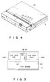
- Fig. 4 is a perspective view showing an appearance of the computer system in which the display is closed.
- a CPU board 3 and a keyboard 36 are arranged on the body 1 of the computer system.
- Fig. 5 is a view showing an arrangement of two 3.5-inch floppy disk drives 32A and 32B included in a computer system.
- the floppy disk drive 32B is disconnected from the connecter 60 and a 2.5-inch hard disk drive 100 is connected to the connecter 42.
- the computer system including the floppy disk drives 32A and 32B can thus be changed to the computer system including the floppy disk drive 32A and the hard disk drive 100.
- Fig. 7 is a view showing an appearance of the floppy disk drive
- Fig. 8 is a view showing an appearance and a configuration of the hard disk drive 100.
- the hard disk drive 100 has a packed structure and is housed in a housing 110 having substantially the same shape as that of the floppy disk drive shown in Fig. 7.
- the hard disk drive 100 is placed on a tray 111, and it can be taken out from the housing 110 by a button 112 with the hard disk drive 100 placed on the tray 111.
- the hard disk drive 100 housed in the housing 110 can be connected to the EBC 40 as the externally-set hard disk drive 90.
- the externally-set hard disk drive can thus be used in a plurality of computer systems. Furthermore, specific software, a large amount of data, etc. can be used in the computer systems.
- the floppy disk drive and hard disk drive are specified by drive numbers A to D to control these disk drives. If the floppy disk drives 32A and 32B are included in the computer system of the present invention as shown in Fig. 5, the floppy disk drives 32A and 32B are specified by the drive numbers A and B, respectively. If the hard disk drive 100 is included in the computer system in place of the floppy disk drive 32B as shown in Fig. 6, the floppy disk drive 32A is specified by the drive number A.
- the hard disk drive 100 is specified by the drive number C (80H) or D (81H).
- the selection of the drive number C or D depends upon whether the externally-set hard disk drive 90 is connected to the EBC 40 or not.
- the externally-set hard disk drive 90 is specified by the drive number C or D in accordance with the switching states of the dip switch 90d.
- the externally-set hard disk drive 90 is specified by the drive number C (80H), as shown in Fig. 9, a predetermined area beginning with address C8000 of a memory map of the computer system is assigned as a memory address area of the HD 90c. If the externally-set hard disk drive 90 is specified by the drive number D (81H), a predetermined area beginning with address CC000 of the memory map is assigned as a memory address area of the HD 90c.
- step C1 it is determined whether the hard RAM is set or not.
- step C2 it is determined in step C2 whether a hard disk drive is internally set in the body 1 of the computer system (see Fig. 6).
- step C6 When no hard disk drive is internally set in step C2, it is determined in step C6 whether a hard disk drive is externally set. When the hard disk drive is externally set in step C6, drive C (drive number 80H) is set to the externally-set hard disk drive (step C9).
- step C5 When the hard disk drive is internally set in the step C2, it is determined in step C5 that the hard disk drive is externally set. When the hard disk drive is not externally set in step C5, drive C (drive number 80H) is set to the internally-set hard disk drive (step C8).
- step C12 When the hard disk drive is externally set in step C5, it is determined in step C12 whether the drive C is set to the externally-set hard disk drive (step C12).
- the drive C is set by the dip switch 90d of the externally-set hard disk drive 90.
- the drive C (drive number 80H) is set to the externally-set hard disk drive and the drive D (drive number 81H) is set to the internally-set hard disk drive (step C13).
- the drive C (drive number 80H) is set to the internally-set hard disk drive and the drive D (drive number 81H) is set to the externally-set hard disk drive (step C14).
- step C3 When the hard RAM is set in step C1, it is determined whether the hard disk drive is externally set or not (step C3). When the hard disk drive is externally set in step C3, it is determined whether the externally-set hard disk drive is specified by the drive C (step C4). When the externally-set hard disk drive is not specified by the drive C in step C4, it is determined whether the hard disk drive is internally set or not (step C7).
- step C7 If the hard disk drive is internally set in step C7, the drive C (drive number 80H) is set to the internally-set disk drive, and the drive D (drive number 81H) is set to the externally-set hard disk drive (step C11). No drives are therefore set to the hard RAM. If the hard disk drive is not internally set in step C7, the drive C (drive number 80H) is set to the hard RAM, and the drive D (drive number 81H) is set to the externally-set hard disk drive (step C10).
- step C15 When the hard disk drive is not externally set in step C3, it is determined in step C15 whether the hard disk drive is internally set or not. If the hard disk drive is internally set in step C15, the drive C (drive number 80H) is set to the internally-set hard disk drive and the drive D (drive number 81H) is set to the hard RAM (step C16). If the hard disk drive is not internally set in step C15, the drive C (drive number 80H) is set to the hard RAM (step C17).
- step C18 When the externally-set hard disk drive is specified by the drive C in step C4, it is determined in step C18 whether the hard disk drive is internally set or not. If the hard disk drive is internally set in step C18, the drive C (drive number 80H) is set to the externally-set hard disk drive, and the drive D (drive number 81H) is set to the internally-set hard disk drive (step C20). No drives are therefore set to the hard RAM. If the hard disk drive is not internally set in step C18, the drive C (drive number 80H) is set to the externally-set hard disk drive, and the drive D (drive number 81H) is set to the hard RAM (step C19).
- the drives are set in accordance with a coupling state of the hard disk drive to the computer system and a setting state of the hard RAM.
- the devices are access-controlled by the CPU 11 in accordance with the flowchart shown in Fig. 11.
- step D1 it is determined whether access to the hard disk drive has been requested.
- a hard disk drive routine program is read out from the ROM 90a and then an externally-set hard disk drive routine is executed in accordance with the read-out routine program (step D4).
- step D2 it is determined whether access to the internally-set hard disk drive is requested or not. If the access is requested, a hard disk drive routine program is read out from the ROM 100a and then an internally-set hard disk drive routine is executed (step D5).
- step D3 it is determined whether the hard RAM is set or not. If the hard RAM is set, a hard RAM routine program is read out from the ROM 12 and a hard RAM routine is executed in accordance with the read-out routine program (step D6).
- a pop-up menu as shown in Fig. 12(a) is displayed on the LCD 37 or the like. If, however, a hard disk drive is externally set to the computer system, pop-up menu data is read out from a ROM of the externally-set hard disk drive and then added to normal pop-up menu data for displaying the pop-up menu shown in Fig. 12(a). A pop-up menu as shown in Fig. 12(b) is thus displayed on the LCD 37. In Fig. 12(b), the pop-up menu shows that the automatic power off time (Drt) of the externally-set hard disk drive is set to 5 minutes.
- Drt automatic power off time
- the selection of a pop-up menu in the CPU 11 will be described according to the flowchart shown in Fig. 13.
- the pop-up menu is selected by inputting a command using a predetermined key of the keyboard 36.
- step E1 When a command for displaying the pop-up menu is input from the keyboard 36, it is determined in step E1 whether the hard disk drive is internally set in the computer system, i.e., whether the hard disk drive 100 is connected to the connecter 42.
- connection state is determined as follows. After the drives are set and before the pop-up menu is selected, information for the device number of each device is automatically set to the head portion of a memory address area assigned to the device, as shown in Fig. 9. If the drive C is set to the hard disk drive 100, information for the device number of the hard disk drive 100 can be obtained by reading out information for the head portion after address C8000. It is thus possible to determine that the hard disk drive 100 is connected to the connecter 42.
- step E1 When it is determined in step E1 that the hard disk drive 100 is not connected to the connecter 42, i.e., when information for the device number of the hard disk drive 100 is not acquired, it is determined in step E2 whether the hard disk drive is externally set to the computer system, i.e., it is determined therein whether the externally-set hard disk drive 90 is connected to the EBC 40. This determination of the connection state also depends upon whether information for the device number of the hard disk drive 90 is acquired or not.
- step E2 When it is determined in step E2 that the externally-set disk drive 90 is not connected to the EBC 40, the pop-up menu is displayed using normal pop-up menu data stored in the ROM 12 in step E5 (see Fig. 12(a)).
- step E2 When it is determined in step E2 that the externally-set hard disk drive 90 is connected to the EBC 40, pop-up menu data for the hard disk drive 90 is read out from the ROM 90a of the hard disk drive 90 and the read-out pop-up menu data is added to the normal pop-up menu data (step E3).
- step E5 the pop-up menu is displayed using the normal pop-up menu data to which the pop-up menu data for the hard disk drive 90 is added (see Fig. 12(b)).
- step E1 When it is determined in step E1 that the hard disk drive 100 is connected to the connecter 42, pop-up menu data for the hard disk drive 100 is read out from the ROM 100a of the hard disk drive 100 and the read-out pop up menu data is added to the normal pop-up menu data (step E4).
- step E5 the pop-up menu is displayed using the normal pop-up menu data to which the pop-up menu data for the hard disk drive 100 is added (see Fig. 12(b)).
- the pop-up menu data for the hard disk drive is automatically read out from the ROM of the hard disk drive and then displayed together with the normal pop-up menu data only when the hard disk drive is coupled to the computer system, without storing the pop-up menu data for the hard disk drive beforehand in the ROM 12.
- the pop-up menu data for the internally-set hard disk drive is read out from the ROM of the internally-set hard disk, the pop-up menu is displayed using the read out pop-up menu data.
- the pop-up menu can precedently be displayed using the pop-up menu data for the externally-set hard disk drive.
- the drives are set to the respective devices in accordance with their objects of use. Accordingly, access control can efficiently be executed.
- the pop-up menu data for the hard disk drive is stored in the ROM of the hard disk drive
- the pop-up menu data is added to the normal pop-up menu data, and the pop-up menu can be displayed using the normal pop-up menu data including the pop-up menu data for the hard disk drive.
- the pop-up menu data for the hard disk drive to be coupled to the computer system need not be stored beforehand and the pop-up menu can be displayed according to whether or not the hard disk drive is coupled to the computer system.
Abstract
In a computer system to which externally and internally hard disk drives (90,100) can be coupled, a drive number is assigned to the hard disk drive according a coupling state of the drive and configure the position of a dip switch (90d) of the external hard disk drive (90). When the external and/or internal hard disk drive (90,100) are/is coupled to the computer system, pop-up menu data for the hard disk drive (90,100) is added to the normal pop-up menu data.
Description
- The present invention relates to a method and an apparatus for controlling drives coupled to a computer system.
- Various portable lap-top type personal computers which can be driven by batteries have recently been developed. These personal computers each include a magnetic recording device such as a floppy disk drive and a hard disk drive.
- In order to advance the system of such a lap-top type personal computer, a magnetic recording device such as a floppy disk drive and a hard disk drive is externally set. Since, therefore, the externally-set magnetic recording device needs to be coupled to the body of the personal computer, the characteristics of the lap-top type computer, such as miniaturization, lightness and portability are lost. Since a connecter and a cable are used to couple the externally-set magnetic recording device to the body of the personal computer, the manufacturing cost of the computer increases and the reliability thereof decreases.
- In a conventional computer including a hard disk drive, the hard disk drive is inherent in the computer and fixed therein. Information stored in the hard disk drive cannot be utilized directly by another computer.
- When an externally-set hard disk drive is coupled to the body of a computer, it cannot be access-controlled when necessary since there is neither a device capable of accessing the externally-set hard disk drive in place of an internally-set hard disk drive nor a device capable of accessing the externally-set hard disk drive in addition to the internally-set hard disk drive.
- In a computer to which an externally-set hard disk drive can be coupled, programs, data and the like must be stored beforehand in the computer system in order to display a pop-up menu including information on the externally-set hard disk drive.
- Consequently, devices capable of controlling an externally-set device coupled to a personal computer according to their purpose of usage, are demanded.
- It is an object of the present invention to provide a method and system for controlling a drive coupled to a computer system.
- According to one aspect of the present invention, there is provided a computer system comprising: a computer body; at least one hard disk drive to be coupled to the computer body, a hard disk drive to be externally coupled to the computer body and having a switch for designating a drive number; and determination and set means for determining whether or not the drive number designated by the switch is a first drive number when the hard disk drive is externally coupled to the computer body, determining whether or not the hard disk drive is externally coupled to the computer body when the hard disk drive is internally coupled to the computer body, and setting the drive number to the coupled hard disk drive in accordance with determination results to obtain memory address regions of the coupled hard disk drive.
- According to another aspect of the present invention, there is provided a computer system comprising: a computer body having a computer memory for storing normal pop-up menu data; at least one hard disk drive to be coupled to the computer body and having a drive memory for storing drive pop-up menu data for the hard disk drive; means for determining whether or not the hard disk drive is coupled to the computer body, reading out the drive pop-up menu data from the drive memory of the coupled hard disk drive when the hard disk drive is coupled to the computer body, reading out the normal pop-up menu data from the computer memory, and adding the drive pop-up menu data to the normal pop-up menu data to obtain added pop-up menu data when the hard disk drive is coupled to the computer body: and display means for displaying a pop-up menu using one of the normal pop-up menu data and the added pop-up menu data in accordance with a determination result.
- This invention can be more fully understood from the following detailed description when taken in conjunction with the accompanying drawings, in which:
- Fig. 1 is a block diagram showing a configuration of a computer system according to an embodiment of the present invention;
- Fig. 2 is a view showing main components of the computer system according to the embodiment of the present invention;
- Fig. 3 is a perspective view showing an appearance and a configuration of the computer system in which a display is opened;
- Fig. 4 is a perspective view showing an appearance of the computer system in which the display is closed;
- Fig. 5 is a view showing an arrangement of two floppy disk drives included in a computer system;
- Fig. 6 is a view showing an arrangement of a floppy disk drive and a hard disk drive included in the computer system;
- Fig. 7 is a view showing an appearance of a floppy disk drive;
- Fig. 8 is a view showing an appearance and a configuration of a hard disk drive;
- Fig. 9 is a view showing memory address areas of drives C and D to be set;
- Figs. 10A and 10B are flowcharts for setting the numbers of the drives;
- Fig. 11 is a flowchart for access-controlling a device;
- Fig. 12 is a view showing an example of displaying a pop-up menu; and
- Fig. 13 is a flowchart for selecting the pop-up menu.
- An embodiment of the present invention will be described with reference to the accompanying drawings.
- Fig. 1 is a block diagram showing a configuration of a computer system according to an embodiment of the present invention. Fig. 2 is a view showing main components of the computer system.
- The computer system shown in Fig. 1 comprises a
system bus 10, a central processing unit (CPU) 11 for controlling the entire computer system, a read only memory (ROM) 12 for storing control programs for the computer system, pop-up menu data, and the like, a random access memory (RAM) 13 for storing data to be processed, a direct memory access controller (DMAC) 14 for direct memory access control, a programmable interrupt controller (PIC) 15 which can be set by programs, a programmable interval timer (PIT) 16 which can be set by programs, a real time clock (RTC) 17 used as a timer module having a driving battery 17a, a large-capacity extendedRAM 18 connectable to a card slot 18a, and abackup RAM 19 for storing data or the like to execute a resume process. - The computer system also comprises a floppy disk controller (FDC) 20.
Floppy disk drives connecters floppy disk drive 32B, a hard disk drive of, for example, 2.5 inches can be coupled to the computer system of the present invention. Accordingly, the computer system can be easily advanced. The method of coupling the hard disk drive to the computer system will be described later. - The computer system further comprises a printer controller (PRT-CONT) 21, a universal asynchronous receiver/transmitter (UART) 22 used as an input and output interface, a keyboard controller (KBC) 23, a display controller (DISP-CONT) 24, a video RAM (VRAM) 25, a
kanji ROM 26, adictionary ROM 27, a power supply interface (PS-IF) 28, an alternating current (AC)adapter 29, apower supply circuit 30 having a power control CPU (PC-CPU) 30a, main batteries (M-BAT) 31A and 31B, a sub-battery (S-BAT) 31C, akeyboard 36, a liquid crystal display (LCD) 37, andpower switch 45. - A 5-inch externally-set
floppy disk drive 33 and aprinter 34 are selectively coupled to the PRT-CONT 21 by a connector. An RS-232C interface unit 35 is connected to theUART 22, if necessary. TheKBC 23 controls a key input from thekeyboard 36 arranged on the body of the computer system. - The DISP-
CONT 24 controls theswingable LCD 37 attached to the body of the computer system, or a cathode ray tube (CRT) display 38 selectively connected to the DISP-CONT 24. A backup voltage VBK is applied to theVRAM 25. Thekanji ROM 26 is used to convert a kanji character code into a kanji character pattern. Thedictionary ROM 27 is used to perform kana-to-kanji conversion. - The PS-IF 28 executes serial data transmission to the PC-
CPU 30a of thepower supply circuit 30. TheAC adapter 29 rectifies and smooths an AC voltage from an externally-set power supply and then supplies a predetermined direct current (DC) voltage to thepower supply circuit 30. Thepower supply circuit 30 supplies a driving voltage to each of the components of the computer system. - The M-
BATs power supply circuit 30, and the driving voltage is supplied from the selected battery to the components. If the battery supplying the driving voltage reaches the limits of usage, that is, if the battery is in a low battery state, the battery is changed to the other battery, by which the driving voltage is supplied. Like these M-BATs BAT 31C can be charged and is used to supply the backup voltage VBK to the components such asRAM 13,RAM 18,backup RAM 19, andVRAM 25, which need to be backed up. - The computer system further comprises an extended bus connector (EBC) 40, a hard
disk drive interface 41, and a systemstate display section 50 for displaying the states of the system. - The EBC 40 is used to extend the functions of the computer system. An externally-set
hard disk drive 90 is selectively connected to the EBC 40. Otherwise, an extended unit (not shown) having various types of components such as a keyboard, a CRT display, a memory, and a connecting portion for coupling the extended unit with the computer system, can selectively be connected to the EBC 40. - As illustrated in Fig. 2, the externally-set
hard disk drive 90 includes aROM 90a, a hard disk controller (HDC) 90b, a hard disk (HD) 90c, and adip switch 90d. TheROM 90a stores routine programs for thehard disk drive 90, pop-up menu data, and the like. TheHDC 90b drives the HD 90c. Thedip switch 90d is used to set a drive number to thehard disk drive 90. - The hard
disk drive interface 41 is used to couple an internally-sethard disk drive 100 to the body of the computer system by aconnecter 42. - The
hard disk drive 100 includes a ROM 100a, a hard disk controller (HDC) 100b, and a hard disk (HD) 100c. The ROM 100a stores routine programs for thehard disk drive 100, pop-up menu data, and the like. TheHDC 100b drives the HD 100c. - The system
state display section 50 includes a plurality of light emitting diodes (LEDs) L1 to L9 operated in accordance with control of the PC-CPU 30a of thepower supply circuit 30. - Fig. 3 is a perspective view showing an appearance and a configuration of the computer system in which a display is opened, and Fig. 4 is a perspective view showing an appearance of the computer system in which the display is closed. As shown in Fig. 3, a
CPU board 3 and akeyboard 36 are arranged on the body 1 of the computer system. - Fig. 5 is a view showing an arrangement of two 3.5-inch
floppy disk drives - In order to advance the computer system (including two floppy disk drives) as shown in Fig. 5 to a computer system (including a floppy disk drive and a hard disk drive) as shown in Fig. 6, the
floppy disk drive 32B is disconnected from theconnecter 60 and a 2.5-inchhard disk drive 100 is connected to theconnecter 42. The computer system including thefloppy disk drives floppy disk drive 32A and thehard disk drive 100. - Fig. 7 is a view showing an appearance of the floppy disk drive, and Fig. 8 is a view showing an appearance and a configuration of the
hard disk drive 100. Thehard disk drive 100 has a packed structure and is housed in ahousing 110 having substantially the same shape as that of the floppy disk drive shown in Fig. 7. Thehard disk drive 100 is placed on a tray 111, and it can be taken out from thehousing 110 by abutton 112 with thehard disk drive 100 placed on the tray 111. Thehard disk drive 100 housed in thehousing 110 can be connected to theEBC 40 as the externally-sethard disk drive 90. - The externally-set hard disk drive can thus be used in a plurality of computer systems. Furthermore, specific software, a large amount of data, etc. can be used in the computer systems.
- When the externally-set
hard disk drive 90 is connected to theEBC 40, it needs to be correctly controlled. In the computer system of the present invention, therefore, the floppy disk drive and hard disk drive are specified by drive numbers A to D to control these disk drives. If thefloppy disk drives floppy disk drives hard disk drive 100 is included in the computer system in place of thefloppy disk drive 32B as shown in Fig. 6, thefloppy disk drive 32A is specified by the drive number A. - The
hard disk drive 100 is specified by the drive number C (80H) or D (81H). The selection of the drive number C or D depends upon whether the externally-sethard disk drive 90 is connected to theEBC 40 or not. The externally-sethard disk drive 90 is specified by the drive number C or D in accordance with the switching states of thedip switch 90d. - If the externally-set
hard disk drive 90 is specified by the drive number C (80H), as shown in Fig. 9, a predetermined area beginning with address C8000 of a memory map of the computer system is assigned as a memory address area of the HD 90c. If the externally-sethard disk drive 90 is specified by the drive number D (81H), a predetermined area beginning with address CC000 of the memory map is assigned as a memory address area of the HD 90c. - When an externally-set hard disk drive and/or an internally-set hard disk drive are/is coupled to a computer system including at least one of floppy disk drives, or when a hard RAM is set in the computer system, drive numbers are set by the CPU 11 in accordance with the flowcharts shown in Figs. 10A and 10B to use the memories of these disk drives. The hard RAM is set in predetermined memory areas of the
RAMs - In step C1, it is determined whether the hard RAM is set or not. When the hard RAM is not set, it is determined in step C2 whether a hard disk drive is internally set in the body 1 of the computer system (see Fig. 6).
- When no hard disk drive is internally set in step C2, it is determined in step C6 whether a hard disk drive is externally set. When the hard disk drive is externally set in step C6, drive C (drive number 80H) is set to the externally-set hard disk drive (step C9).
- When the hard disk drive is internally set in the step C2, it is determined in step C5 that the hard disk drive is externally set. When the hard disk drive is not externally set in step C5, drive C (drive number 80H) is set to the internally-set hard disk drive (step C8).
- When the hard disk drive is externally set in step C5, it is determined in step C12 whether the drive C is set to the externally-set hard disk drive (step C12). The drive C is set by the
dip switch 90d of the externally-sethard disk drive 90. - When the externally-set hard disk drive is specified by the drive C in step C12, the drive C (drive number 80H) is set to the externally-set hard disk drive and the drive D (drive number 81H) is set to the internally-set hard disk drive (step C13). When the externally-set hard disk drive is not specified by the drive C in step C12, the drive C (drive number 80H) is set to the internally-set hard disk drive and the drive D (drive number 81H) is set to the externally-set hard disk drive (step C14).
- When the hard RAM is set in step C1, it is determined whether the hard disk drive is externally set or not (step C3). When the hard disk drive is externally set in step C3, it is determined whether the externally-set hard disk drive is specified by the drive C (step C4). When the externally-set hard disk drive is not specified by the drive C in step C4, it is determined whether the hard disk drive is internally set or not (step C7).
- If the hard disk drive is internally set in step C7, the drive C (drive number 80H) is set to the internally-set disk drive, and the drive D (drive number 81H) is set to the externally-set hard disk drive (step C11). No drives are therefore set to the hard RAM. If the hard disk drive is not internally set in step C7, the drive C (drive number 80H) is set to the hard RAM, and the drive D (drive number 81H) is set to the externally-set hard disk drive (step C10).
- When the hard disk drive is not externally set in step C3, it is determined in step C15 whether the hard disk drive is internally set or not. If the hard disk drive is internally set in step C15, the drive C (drive number 80H) is set to the internally-set hard disk drive and the drive D (drive number 81H) is set to the hard RAM (step C16). If the hard disk drive is not internally set in step C15, the drive C (drive number 80H) is set to the hard RAM (step C17).
- When the externally-set hard disk drive is specified by the drive C in step C4, it is determined in step C18 whether the hard disk drive is internally set or not. If the hard disk drive is internally set in step C18, the drive C (drive number 80H) is set to the externally-set hard disk drive, and the drive D (drive number 81H) is set to the internally-set hard disk drive (step C20). No drives are therefore set to the hard RAM. If the hard disk drive is not internally set in step C18, the drive C (drive number 80H) is set to the externally-set hard disk drive, and the drive D (drive number 81H) is set to the hard RAM (step C19).
- As described above, the drives are set in accordance with a coupling state of the hard disk drive to the computer system and a setting state of the hard RAM.
- After the drives are set, the devices are access-controlled by the CPU 11 in accordance with the flowchart shown in Fig. 11.
- In step D1, it is determined whether access to the hard disk drive has been requested. When the access is requested, a hard disk drive routine program is read out from the
ROM 90a and then an externally-set hard disk drive routine is executed in accordance with the read-out routine program (step D4). - In step D2, it is determined whether access to the internally-set hard disk drive is requested or not. If the access is requested, a hard disk drive routine program is read out from the ROM 100a and then an internally-set hard disk drive routine is executed (step D5).
- In step D3, it is determined whether the hard RAM is set or not. If the hard RAM is set, a hard RAM routine program is read out from the
ROM 12 and a hard RAM routine is executed in accordance with the read-out routine program (step D6). - In a computer system having a floppy disk only, usually, a pop-up menu as shown in Fig. 12(a) is displayed on the
LCD 37 or the like. If, however, a hard disk drive is externally set to the computer system, pop-up menu data is read out from a ROM of the externally-set hard disk drive and then added to normal pop-up menu data for displaying the pop-up menu shown in Fig. 12(a). A pop-up menu as shown in Fig. 12(b) is thus displayed on theLCD 37. In Fig. 12(b), the pop-up menu shows that the automatic power off time (Drt) of the externally-set hard disk drive is set to 5 minutes. - The selection of a pop-up menu in the CPU 11 will be described according to the flowchart shown in Fig. 13. The pop-up menu is selected by inputting a command using a predetermined key of the
keyboard 36. - When a command for displaying the pop-up menu is input from the
keyboard 36, it is determined in step E1 whether the hard disk drive is internally set in the computer system, i.e., whether thehard disk drive 100 is connected to theconnecter 42. - For example, the connection state is determined as follows. After the drives are set and before the pop-up menu is selected, information for the device number of each device is automatically set to the head portion of a memory address area assigned to the device, as shown in Fig. 9. If the drive C is set to the
hard disk drive 100, information for the device number of thehard disk drive 100 can be obtained by reading out information for the head portion after address C8000. It is thus possible to determine that thehard disk drive 100 is connected to theconnecter 42. - When it is determined in step E1 that the
hard disk drive 100 is not connected to theconnecter 42, i.e., when information for the device number of thehard disk drive 100 is not acquired, it is determined in step E2 whether the hard disk drive is externally set to the computer system, i.e., it is determined therein whether the externally-sethard disk drive 90 is connected to theEBC 40. This determination of the connection state also depends upon whether information for the device number of thehard disk drive 90 is acquired or not. - When it is determined in step E2 that the externally-set
disk drive 90 is not connected to theEBC 40, the pop-up menu is displayed using normal pop-up menu data stored in theROM 12 in step E5 (see Fig. 12(a)). - When it is determined in step E2 that the externally-set
hard disk drive 90 is connected to theEBC 40, pop-up menu data for thehard disk drive 90 is read out from theROM 90a of thehard disk drive 90 and the read-out pop-up menu data is added to the normal pop-up menu data (step E3). In step E5, the pop-up menu is displayed using the normal pop-up menu data to which the pop-up menu data for thehard disk drive 90 is added (see Fig. 12(b)). - When it is determined in step E1 that the
hard disk drive 100 is connected to theconnecter 42, pop-up menu data for thehard disk drive 100 is read out from the ROM 100a of thehard disk drive 100 and the read-out pop up menu data is added to the normal pop-up menu data (step E4). In step E5, the pop-up menu is displayed using the normal pop-up menu data to which the pop-up menu data for thehard disk drive 100 is added (see Fig. 12(b)). - Consequently, the pop-up menu data for the hard disk drive is automatically read out from the ROM of the hard disk drive and then displayed together with the normal pop-up menu data only when the hard disk drive is coupled to the computer system, without storing the pop-up menu data for the hard disk drive beforehand in the
ROM 12. - If the externally- and internally-set hard disk drives are coupled to the computer system, the pop-up menu data for the internally-set hard disk drive is read out from the ROM of the internally-set hard disk, the pop-up menu is displayed using the read out pop-up menu data. However, the pop-up menu can precedently be displayed using the pop-up menu data for the externally-set hard disk drive.
- As described above, in the present invention, when the externally-set hard disk drive and/or the internally-set hard disk drive are/is coupled to the computer system, the drives are set to the respective devices in accordance with their objects of use. Accordingly, access control can efficiently be executed.
- When the hard disk drive is coupled to the computer system, since the pop-up menu data for the hard disk drive is stored in the ROM of the hard disk drive, the pop-up menu data is added to the normal pop-up menu data, and the pop-up menu can be displayed using the normal pop-up menu data including the pop-up menu data for the hard disk drive. In the computer system of the present invention, therefore, the pop-up menu data for the hard disk drive to be coupled to the computer system, need not be stored beforehand and the pop-up menu can be displayed according to whether or not the hard disk drive is coupled to the computer system.
Claims (11)
- A computer system characterized by comprising:
a computer body (1);
at least one hard disk drive (90;100) to be coupled to the computer body (1), a hard disk drive (90) to be externally coupled to the computer body (1) and having a switch (90d) for designating a drive number; and
determination and set means (11) for determining whether or not the drive number designated by the switch (90d) is a first drive number when the hard disk drive (90) is externally coupled to the computer body (1), determining whether or not the hard disk drive (90) is externally coupled to the computer body (1) when the hard disk drive (100) is internally coupled to the computer body (1), and setting the drive number to the coupled hard disk drive (90;100) in accordance with determination results to obtain memory address regions of the coupled hard disk drive. - The system according to claim 1, characterized in that the computer body (1) includes at least one floppy disk drive (32A;32B).
- The system according to claim 1, characterized in that the hard disk drive (90;100) further includes a hard disk (90c;100c), a hard disk controller (90b;100b), and a memory (90a;100a).
- The system according to claim 1, characterized in that the first drive number is set to the externally coupled hard disk drive (90) when the drive number designated by the switch (90d) is the first drive number.
- The system according to claim 1, characterized in that the first drive number is set to the internally coupled hard disk drive (100) when the hard disk drive (90) is not externally coupled to the computer body (1) and the hard disk drive (100) is internally coupled to the computer body (1).
- A method for setting a drive number to at least one hard disk drive coupled to a computer system, a hard disk drive to be externally coupled to the computer system and having a switch for designating a drive number, characterized by comprising the steps of:
determining whether or not the drive number designated by the switch is a first drive number when the hard disk drive is externally coupled to the computer system;
determining whether or not the hard disk drive is internally connected to the computer system when the hard disk drive is externally coupled to the computer body; and
setting the drive number to the coupled hard disk drive in accordance with determination results to obtain memory address regions of the coupled hard disk drive. - The method according to claim 6, characterized in that the first drive number is set to the externally coupled hard disk drive when the drive number designated by the switch is the first drive number.
- The method according to claim 6, characterized in that the first drive number is set to the internally coupled hard disk drive when the hard disk drive is not externally coupled to the computer system and the hard disk drive is internally coupled to the computer system.
- A computer system characterized by comprising:
a computer body (1) having a computer memory (12) for storing normal pop-up menu data;
at least one hard disk drive (90;100) to be coupled to the computer body (1) and having a drive memory (90a;100a) for storing drive pop-up menu data for the hard disk drive (90;100);
means (11) for determining whether or not the hard disk drive (90;100) is coupled to the computer body (1), reading out the drive pop-up menu data from the drive memory (90a;100a) of the coupled hard disk drive (90;100) when the hard disk drive (90;100) is coupled to the computer body (1), reading out the normal pop-up menu data from the computer memory (12), and adding the drive pop-up menu data to the normal pop-up menu data to obtain added pop-up menu data when the hard disk drive (90;100) is coupled to the computer body (1): and
display means (37) for displaying a pop-up menu using one of the normal pop-up menu data and the added pop-up menu data in accordance with a determination result. - The system according to claim 9, characterized in that the pop-up menu using the normal pop-up menu is displayed when the hard disk drive (90;100) is coupled to the computer body (1).
- The system according to claim 9, characterized in that the pop-up menu using the added pop-up menu is displayed when the hard disk drive (90;100) is not coupled to the computer body (1).
Applications Claiming Priority (4)
| Application Number | Priority Date | Filing Date | Title |
|---|---|---|---|
| JP16621690 | 1990-06-25 | ||
| JP16621590 | 1990-06-25 | ||
| JP166216/90 | 1990-06-25 | ||
| JP166215/90 | 1990-06-25 |
Publications (2)
| Publication Number | Publication Date |
|---|---|
| EP0464551A2 true EP0464551A2 (en) | 1992-01-08 |
| EP0464551A3 EP0464551A3 (en) | 1992-11-19 |
Family
ID=26490666
Family Applications (1)
| Application Number | Title | Priority Date | Filing Date |
|---|---|---|---|
| EP19910110366 Withdrawn EP0464551A3 (en) | 1990-06-25 | 1991-06-24 | Method and apparatus for controlling drives coupled to a computer system |
Country Status (4)
| Country | Link |
|---|---|
| US (1) | US5581786A (en) |
| EP (1) | EP0464551A3 (en) |
| JP (1) | JPH04260916A (en) |
| KR (1) | KR930008049B1 (en) |
Cited By (1)
| Publication number | Priority date | Publication date | Assignee | Title |
|---|---|---|---|---|
| CN1042676C (en) * | 1994-12-03 | 1999-03-24 | 联华电子股份有限公司 | Circuit for exchanging floppy disk drives |
Families Citing this family (8)
| Publication number | Priority date | Publication date | Assignee | Title |
|---|---|---|---|---|
| US5896546A (en) * | 1996-11-01 | 1999-04-20 | International Business Machines Corporation | "Sticky" logical drive letter assignments |
| KR100551191B1 (en) * | 1997-05-16 | 2006-05-25 | 매그나칩 반도체 유한회사 | Method for uniquely identifying logical units in a computer system |
| US6157768A (en) * | 1999-02-03 | 2000-12-05 | Matsushita Electric Industrial Co., Ltd. | Recording/reproducing apparatus and information medium transfer method |
| KR100604893B1 (en) * | 2004-08-14 | 2006-07-28 | 삼성전자주식회사 | Method for setting communication parameters between a host system and a peripheral device |
| JP2007052727A (en) * | 2005-08-19 | 2007-03-01 | Toshiba Corp | Information processor and access method |
| JP2007052728A (en) * | 2005-08-19 | 2007-03-01 | Toshiba Corp | Information processor and access method |
| KR100810473B1 (en) * | 2006-03-08 | 2008-03-07 | 김예진 | variable method for source path of operating system and the computer system for it |
| US8838843B2 (en) * | 2011-08-04 | 2014-09-16 | Mitsubishi Electric Corporation | Electronic apparatus |
Citations (3)
| Publication number | Priority date | Publication date | Assignee | Title |
|---|---|---|---|---|
| GB2188761A (en) * | 1986-04-04 | 1987-10-07 | Mitsubishi Electric Corp | Type determination in disk device selector circuits |
| EP0314093A2 (en) * | 1987-10-27 | 1989-05-03 | Core International Inc. | Disc interface circuit |
| WO1990006554A1 (en) * | 1988-11-30 | 1990-06-14 | Laboratoire Europeen De Recherches Electroniques Avancees | Computer and starting-up process of said computer |
Family Cites Families (13)
| Publication number | Priority date | Publication date | Assignee | Title |
|---|---|---|---|---|
| US4583194A (en) * | 1981-12-23 | 1986-04-15 | Pitney Bowes Inc. | Fixed disk controller for use in a word processing system |
| US4833554A (en) * | 1987-02-25 | 1989-05-23 | Tandon Corporation | Hard disk drive module and receptacle therefor |
| US4866601A (en) * | 1987-09-24 | 1989-09-12 | Ncr Corporation | Digital data bus architecture for computer disk drive controller |
| US5075805A (en) * | 1988-02-25 | 1991-12-24 | Tandon Corporation | Disk drive controller system |
| JPH01248256A (en) * | 1988-03-30 | 1989-10-03 | Toshiba Corp | Input/output control system |
| US4914656A (en) * | 1988-06-28 | 1990-04-03 | Storage Technology Corporation | Disk drive memory |
| US5014193A (en) * | 1988-10-14 | 1991-05-07 | Compaq Computer Corporation | Dynamically configurable portable computer system |
| US5065262A (en) * | 1988-11-30 | 1991-11-12 | Quantum Corporation | Removable and transportable hard disk subsystem |
| US4982324A (en) * | 1988-12-19 | 1991-01-01 | International Business Machines Corporation | Method of and system for using device drivers to couple the communication and data storage of remote computer systems |
| US5097439A (en) * | 1989-11-08 | 1992-03-17 | Quantum Corporation | Expansible fixed disk drive subsystem for computer |
| US5058004A (en) * | 1990-01-19 | 1991-10-15 | Gonen Ravid | Computer gate control circuitry and apparatus to enable a single computer to simultaneously and selectively control a multiplicity of hard disk drives |
| US5153817A (en) * | 1990-02-09 | 1992-10-06 | Kabushiki Kaisha Toshiba | Electronic apparatus system including an expansion device removably connected to a removable battery pack |
| US5018095A (en) * | 1990-02-15 | 1991-05-21 | Seagate Technology, Inc. | Universal disk drive type emulation for IBM PC-AT computers |
-
1991
- 1991-06-24 EP EP19910110366 patent/EP0464551A3/en not_active Withdrawn
- 1991-06-25 JP JP3153454A patent/JPH04260916A/en active Pending
- 1991-06-25 KR KR1019910010945A patent/KR930008049B1/en not_active IP Right Cessation
-
1995
- 1995-01-04 US US08/383,692 patent/US5581786A/en not_active Expired - Fee Related
Patent Citations (3)
| Publication number | Priority date | Publication date | Assignee | Title |
|---|---|---|---|---|
| GB2188761A (en) * | 1986-04-04 | 1987-10-07 | Mitsubishi Electric Corp | Type determination in disk device selector circuits |
| EP0314093A2 (en) * | 1987-10-27 | 1989-05-03 | Core International Inc. | Disc interface circuit |
| WO1990006554A1 (en) * | 1988-11-30 | 1990-06-14 | Laboratoire Europeen De Recherches Electroniques Avancees | Computer and starting-up process of said computer |
Non-Patent Citations (1)
| Title |
|---|
| IBM TECHNICAL DISCLOSURE BULLETIN. vol. 29, no. 1, June 1986, NEW YORK US page 177; 'METHOD TO DISPLAY THE SYSTEM CONFIGURATION OF A PERSONAL COMPUTER' * |
Cited By (1)
| Publication number | Priority date | Publication date | Assignee | Title |
|---|---|---|---|---|
| CN1042676C (en) * | 1994-12-03 | 1999-03-24 | 联华电子股份有限公司 | Circuit for exchanging floppy disk drives |
Also Published As
| Publication number | Publication date |
|---|---|
| KR920001357A (en) | 1992-01-30 |
| EP0464551A3 (en) | 1992-11-19 |
| US5581786A (en) | 1996-12-03 |
| JPH04260916A (en) | 1992-09-16 |
| KR930008049B1 (en) | 1993-08-25 |
Similar Documents
| Publication | Publication Date | Title |
|---|---|---|
| KR100666518B1 (en) | Portable electronic device comprising common serial bus connector | |
| AU695961B2 (en) | Portable computer keyboard for use with a plurality of different host computers | |
| US5909596A (en) | Self-configuring PC card with connector capable of using the pin configuration of an attached peripheral to identify the peripheral | |
| US6175919B1 (en) | Method and apparatus for upgrading BIOS using a serial communication | |
| US6341320B1 (en) | Computer docking station with PCMCIA card slot | |
| US5341316A (en) | Personal computer system allowing selective use of built-in and external keyboards by means of selector | |
| US5978821A (en) | Smart modular electronic machine | |
| US6298388B1 (en) | Electronic apparatus and method for discriminating whether a first or second card is attached thereto | |
| US20050174710A1 (en) | Electronic device and power supply control method | |
| EP0464551A2 (en) | Method and apparatus for controlling drives coupled to a computer system | |
| CA2117065A1 (en) | Portable computer keyboard | |
| US20040078498A1 (en) | Device driver and device | |
| EP0482589A2 (en) | Method and apparatus for controlling bus in computer system to which expansion unit is connectable | |
| US20040177202A1 (en) | Apparatus and method for generating hot-plug signal | |
| US5737610A (en) | System and method for providing data and program code to a card for use by a reader | |
| EP0464550A2 (en) | A computer system having storage devices | |
| US5428739A (en) | Display control system for setting gray scale levels using popup menu | |
| US6948006B1 (en) | Host system that provides device driver for connected external peripheral if device driver type is available or device driver is downloaded from memory of external peripheral to host system | |
| EP0326102A2 (en) | Method and apparatus for selecting a keyboard on a computer system | |
| US7380141B2 (en) | Transferring data without completing a boot process | |
| EP0516324A1 (en) | Personal computer with alternate system controller | |
| US20060212631A1 (en) | Automatic status assignment logic circuit apparatus for bay devices | |
| EP0459427A2 (en) | Portable computer with peripheral units for extended funtionality | |
| US20090014521A1 (en) | Card reader | |
| CN113296815A (en) | Portable burning device |
Legal Events
| Date | Code | Title | Description |
|---|---|---|---|
| PUAI | Public reference made under article 153(3) epc to a published international application that has entered the european phase |
Free format text: ORIGINAL CODE: 0009012 |
|
| 17P | Request for examination filed |
Effective date: 19910719 |
|
| AK | Designated contracting states |
Kind code of ref document: A2 Designated state(s): DE FR GB |
|
| PUAL | Search report despatched |
Free format text: ORIGINAL CODE: 0009013 |
|
| AK | Designated contracting states |
Kind code of ref document: A3 Designated state(s): DE FR GB |
|
| STAA | Information on the status of an ep patent application or granted ep patent |
Free format text: STATUS: THE APPLICATION HAS BEEN WITHDRAWN |
|
| 18W | Application withdrawn |
Withdrawal date: 19940307 |
|
| R18W | Application withdrawn (corrected) |
Effective date: 19940307 |