EP0464423A1 - Device for controlling the total energy-consumption of an electricity consumer - Google Patents
Device for controlling the total energy-consumption of an electricity consumer Download PDFInfo
- Publication number
- EP0464423A1 EP0464423A1 EP91109755A EP91109755A EP0464423A1 EP 0464423 A1 EP0464423 A1 EP 0464423A1 EP 91109755 A EP91109755 A EP 91109755A EP 91109755 A EP91109755 A EP 91109755A EP 0464423 A1 EP0464423 A1 EP 0464423A1
- Authority
- EP
- European Patent Office
- Prior art keywords
- arrangement according
- interval
- current flow
- value
- limit value
- Prior art date
- Legal status (The legal status is an assumption and is not a legal conclusion. Google has not performed a legal analysis and makes no representation as to the accuracy of the status listed.)
- Granted
Links
- 238000005265 energy consumption Methods 0.000 title claims abstract description 59
- 230000005611 electricity Effects 0.000 title claims abstract description 23
- 238000012545 processing Methods 0.000 claims abstract description 40
- 230000001419 dependent effect Effects 0.000 claims abstract description 3
- 230000001965 increasing effect Effects 0.000 claims description 3
- 230000003247 decreasing effect Effects 0.000 claims description 2
- 230000004913 activation Effects 0.000 claims 1
- 238000012544 monitoring process Methods 0.000 description 5
- XLYOFNOQVPJJNP-UHFFFAOYSA-N water Substances O XLYOFNOQVPJJNP-UHFFFAOYSA-N 0.000 description 5
- 238000000034 method Methods 0.000 description 4
- 230000008569 process Effects 0.000 description 4
- 230000008878 coupling Effects 0.000 description 3
- 238000010168 coupling process Methods 0.000 description 3
- 238000005859 coupling reaction Methods 0.000 description 3
- 238000013461 design Methods 0.000 description 3
- 238000010586 diagram Methods 0.000 description 3
- 230000006870 function Effects 0.000 description 3
- 238000010438 heat treatment Methods 0.000 description 3
- 230000009467 reduction Effects 0.000 description 3
- 230000009471 action Effects 0.000 description 2
- 238000010411 cooking Methods 0.000 description 2
- 238000013459 approach Methods 0.000 description 1
- 235000008429 bread Nutrition 0.000 description 1
- 230000008859 change Effects 0.000 description 1
- 230000000694 effects Effects 0.000 description 1
- 238000005516 engineering process Methods 0.000 description 1
- 230000001939 inductive effect Effects 0.000 description 1
- 230000013011 mating Effects 0.000 description 1
- 238000005259 measurement Methods 0.000 description 1
- 238000004377 microelectronic Methods 0.000 description 1
- 230000000737 periodic effect Effects 0.000 description 1
- 238000000819 phase cycle Methods 0.000 description 1
- 230000010363 phase shift Effects 0.000 description 1
- 238000004393 prognosis Methods 0.000 description 1
- 238000003303 reheating Methods 0.000 description 1
- 238000009418 renovation Methods 0.000 description 1
- 238000009420 retrofitting Methods 0.000 description 1
- 230000000630 rising effect Effects 0.000 description 1
- 239000004065 semiconductor Substances 0.000 description 1
- 239000007858 starting material Substances 0.000 description 1
- 230000001960 triggered effect Effects 0.000 description 1
- 238000005406 washing Methods 0.000 description 1
Images


Classifications
-
- H—ELECTRICITY
- H02—GENERATION; CONVERSION OR DISTRIBUTION OF ELECTRIC POWER
- H02J—CIRCUIT ARRANGEMENTS OR SYSTEMS FOR SUPPLYING OR DISTRIBUTING ELECTRIC POWER; SYSTEMS FOR STORING ELECTRIC ENERGY
- H02J3/00—Circuit arrangements for ac mains or ac distribution networks
- H02J3/12—Circuit arrangements for ac mains or ac distribution networks for adjusting voltage in ac networks by changing a characteristic of the network load
- H02J3/14—Circuit arrangements for ac mains or ac distribution networks for adjusting voltage in ac networks by changing a characteristic of the network load by switching loads on to, or off from, network, e.g. progressively balanced loading
- H02J3/144—Demand-response operation of the power transmission or distribution network
-
- H—ELECTRICITY
- H02—GENERATION; CONVERSION OR DISTRIBUTION OF ELECTRIC POWER
- H02J—CIRCUIT ARRANGEMENTS OR SYSTEMS FOR SUPPLYING OR DISTRIBUTING ELECTRIC POWER; SYSTEMS FOR STORING ELECTRIC ENERGY
- H02J2310/00—The network for supplying or distributing electric power characterised by its spatial reach or by the load
- H02J2310/50—The network for supplying or distributing electric power characterised by its spatial reach or by the load for selectively controlling the operation of the loads
- H02J2310/54—The network for supplying or distributing electric power characterised by its spatial reach or by the load for selectively controlling the operation of the loads according to a pre-established time schedule
-
- H—ELECTRICITY
- H02—GENERATION; CONVERSION OR DISTRIBUTION OF ELECTRIC POWER
- H02J—CIRCUIT ARRANGEMENTS OR SYSTEMS FOR SUPPLYING OR DISTRIBUTING ELECTRIC POWER; SYSTEMS FOR STORING ELECTRIC ENERGY
- H02J2310/00—The network for supplying or distributing electric power characterised by its spatial reach or by the load
- H02J2310/50—The network for supplying or distributing electric power characterised by its spatial reach or by the load for selectively controlling the operation of the loads
- H02J2310/56—The network for supplying or distributing electric power characterised by its spatial reach or by the load for selectively controlling the operation of the loads characterised by the condition upon which the selective controlling is based
- H02J2310/58—The condition being electrical
- H02J2310/60—Limiting power consumption in the network or in one section of the network, e.g. load shedding or peak shaving
-
- Y—GENERAL TAGGING OF NEW TECHNOLOGICAL DEVELOPMENTS; GENERAL TAGGING OF CROSS-SECTIONAL TECHNOLOGIES SPANNING OVER SEVERAL SECTIONS OF THE IPC; TECHNICAL SUBJECTS COVERED BY FORMER USPC CROSS-REFERENCE ART COLLECTIONS [XRACs] AND DIGESTS
- Y02—TECHNOLOGIES OR APPLICATIONS FOR MITIGATION OR ADAPTATION AGAINST CLIMATE CHANGE
- Y02B—CLIMATE CHANGE MITIGATION TECHNOLOGIES RELATED TO BUILDINGS, e.g. HOUSING, HOUSE APPLIANCES OR RELATED END-USER APPLICATIONS
- Y02B70/00—Technologies for an efficient end-user side electric power management and consumption
- Y02B70/30—Systems integrating technologies related to power network operation and communication or information technologies for improving the carbon footprint of the management of residential or tertiary loads, i.e. smart grids as climate change mitigation technology in the buildings sector, including also the last stages of power distribution and the control, monitoring or operating management systems at local level
- Y02B70/3225—Demand response systems, e.g. load shedding, peak shaving
-
- Y—GENERAL TAGGING OF NEW TECHNOLOGICAL DEVELOPMENTS; GENERAL TAGGING OF CROSS-SECTIONAL TECHNOLOGIES SPANNING OVER SEVERAL SECTIONS OF THE IPC; TECHNICAL SUBJECTS COVERED BY FORMER USPC CROSS-REFERENCE ART COLLECTIONS [XRACs] AND DIGESTS
- Y04—INFORMATION OR COMMUNICATION TECHNOLOGIES HAVING AN IMPACT ON OTHER TECHNOLOGY AREAS
- Y04S—SYSTEMS INTEGRATING TECHNOLOGIES RELATED TO POWER NETWORK OPERATION, COMMUNICATION OR INFORMATION TECHNOLOGIES FOR IMPROVING THE ELECTRICAL POWER GENERATION, TRANSMISSION, DISTRIBUTION, MANAGEMENT OR USAGE, i.e. SMART GRIDS
- Y04S20/00—Management or operation of end-user stationary applications or the last stages of power distribution; Controlling, monitoring or operating thereof
- Y04S20/20—End-user application control systems
- Y04S20/222—Demand response systems, e.g. load shedding, peak shaving
Definitions
- the invention relates to an arrangement for controlling the total energy consumption of an electricity consumer, in which both a controllable switch and a current flow sensor delivering a current flow signal are switched on in several circuits for each consumer device in addition to an overload switch in which the current flow signals, possibly via intermediate stages such as amplifiers, are fed to a processing unit (computer), a summation signal being formed, preferably from the current flow signals, and the controllable switches being connected to the processing unit such that at least one the switch is actuated and the associated circuit is interrupted when the sum signal exceeds a limit value.
- a processing unit computer
- a system for controlling the electrical energy consumption (total power consumption), preferably in households, is known, in which the current is measured in each circuit to the consumer devices and the connection or disconnection of consumers after comparing the electrical energy obtained in a measurement period with a limit value.
- the current sensors in the individual circuits are used to determine the current flow times in the individual circuits.
- the new electricity meters can have a maximum monitor, which is also coupled to a timer.
- a basic fee of around DM 300 to DM 400 per kilowatt should be in question, so that it is very interesting whether the peak value of the decrease in private households is, for example, 4 kW or 8 kW with simultaneous operation of all large consumers.
- the actual acceptance performance is therefore an important part of the cost, which the customer can influence at any moment only in extreme discipline. Larger commercial facilities are already overwhelmed by this.
- the aim is to achieve the lowest possible fluctuations in electricity consumption over the course of the day and, if necessary, over the year for individual customers, and also to avoid exceeding a low average value or to burden it with tariff surcharges.
- the invention has for its object to provide an arrangement of the type mentioned in such a way that in the event of a change in the tariff system in the area of an electricity supply company (EVU), the large number of customer systems are designed in a simple manner and, if necessary, converted subsequently will can, in such a way that a low value of the permitted current consumption is automatically complied with as far as possible for each individual customer and this value can reliably be prevented from being exceeded.
- ENU electricity supply company
- a forecast is therefore given for the last part of a time period that is decisive for the tariff calculation based on the previous larger part, so that as little part of the permissible energy consumption as possible remains unused by the electricity company.
- the time period TP is increased over time, e.g. throughout the year, shifted by one interval TI.
- the energy consumption in total or in individual circuits can be continuously recorded and evaluated for a forecast in the last interval of the time period specified by the tariff design.
- the total value can simply depend on the current supplied in a manner known per se. In order to meet special requirements on the part of the electricity works, the total value can also depend on the reactive power supplied or the active power supplied.
- a particularly precise adjustment of the actual consumption to the value permitted by the tariff results if one also continuously measures the energy consumed within the subsequent (last) interval for which a forecast was made and the permitted limit value in accordance with the until the end of this Interval of still consumable energy changes.
- the limit value can be adjusted continuously; Expediently, the adjustment is made in descending stages, the duration of these stages being one or more minutes in order to keep the effort low, but nevertheless to do justice to the changes in consumption that are possible in practical operation.
- the design is such that if the limit value is exceeded by the current energy consumption of at least one of the connected devices, consumption is reduced or completely or partially switched off in accordance with a certain order of priority, or entirely if the limit value is undershot by more than a predetermined threshold value or partially turned on. So on the one hand prevents the given limits from being exceeded, but on the other hand also avoids that too much consumer load remains switched off and the given framework of energy supply is thus not fully utilized.
- the processing unit can easily record such switch-off processes, and it can also switch it on again if necessary in a different order than that which was intended for the switch-off.
- At least one of the consumer devices can be operated at intervals of e.g. periodically switched on and off for a few seconds or minutes. It is also possible to switch two or more consumers on and off alternately periodically: This way the total load can be reduced without one of the devices being switched off completely.
- a reduction in the load is also possible in that at least one of the consumer devices in phase control is switched on and off again in each alternating current period.
- the threshold value for switching on the consumer when approaching the limit value should be kept low and may correspond to an energy consumption of a certain percentage, for example 1 to 3%, of the limit value output. If the limit power corresponds to 4 kW, another consumer device can be switched on if the total energy consumption drops below around 3,900 watts, corresponding to a reduction of 2.5%.
- both a current sensor and a controllable switch can be switched on in several circuits and that the signals of all current sensors are fed to a control unit to which the controllable switches are connected such that at least one of the switches is actuated and the associated circuit is interrupted when the sum signal exceeds the limit. In this way, the scope of consumption granted in a new tariff can be used automatically, without supervision by the electricity consumer.
- the current flow sensor is useful as an inductive sensor, e.g. as a current transformer. An intervention in the line carrying the consumer current is then not necessary.
- the controllable switch can be a magnetic switch controllable by an electric current, for example a contactor. However, it can also be designed as an electronically controllable element, for example a thyristor; Such a configuration is particularly suitable when periodic switching on and off at intervals or in phase cycles is to be carried out.
- the processing unit a program stage with an input part, an input unit, a limit value stage, a timer and an output unit can be combined in a starter device, if appropriate together with further appropriate circuit stages.
- the signals of all current sensors are processed in the control unit and information is thus given about the total load caused by the consumer devices.
- the signals are generated according to a program that can be entered or modified by the user, the electricity consumer; it can be determined in which order one or more consumer devices are switched off or their power consumption is reduced if the limit value is exceeded.
- the program is used to implement switch-on interlocks and / or timeout controls for any consumer devices or groups thereof according to a predetermined priority.
- the ranking does not have to be fixed; it can also be adjusted according to additional conditions.
- the priority for a particular consumer device can be selected differently at different times; In the midday hours the kitchen stove can be privileged, in the evening an electric boiler for showering and in the night or in the afternoon the washing machine or the dishwasher or a hot water tank, which then supplies preheated water during the day, if necessary without reheating.
- the setpoints that play a role here can be saved permanently or temporarily (by ROM and RAM).
- a controllable switch can not only cause a complete interruption of the power supply, but it is also possible to switch to a lower power consumption.
- one or both of the plates can be switched off from the kitchen stove when the total load is high, but at least one plate should remain switched on for a longer cooking process.
- the respective consumption can be sensed by the assigned current sensor and, if the current requirement of this plate is reduced, another one can be switched on temporarily.
- Lamp power circuits can be continuously set in terms of their power consumption analogously to conventional dimming devices, which is easy to implement by means of a controlled semiconductor switch (thyristor) instead of a magnetic switch.
- thyristor controlled semiconductor switch
- the program can be set or subsequently changed using a keyboard or a magnetic card, which is activated via a built-in reading device.
- the latter solution is particularly suitable for cases in which a new load profile is to be assigned to the customer from the power plant.
- a particularly simple embodiment results if the controllable switch, the current flow sensor and the overload switch for a circuit are combined to form one structural unit.
- the current flow sensor can also be called a sensor and sends the current flow signal to the outside.
- the controllable switch receives a signal from the outside and then opens or closes a contact connection.
- Such an assembly thus acts as a sensor actuator.
- Such a unit is particularly useful when retrofitting is to be done; then the unit can also be mechanically arranged in the place of a previous fuse, so that major renovation work is not necessary.
- the structural unit can be designed in such a way that it can be installed in the existing electrical distribution board at the location of the previously required securing element, which can thus be converted in a simple manner for a new tariff system.
- At least one switch interrupting the circuit can be controlled on the one hand for opening and closing by the processing unit and on the other hand can be opened automatically in the event of overload, but can only be closed again by hand.
- only one contact path is installed in the circuit, but on the one hand it can act automatically as a fuse protection in the circuit in question, and, on the other hand, it can be opened and closed again from the outside for the desired influencing of the total energy consumption.
- Such a switch is preferably designed as a normally closed contact, so that it normally allows the current to flow freely through the circuit without any interference.
- the contact path can then be coupled, on the one hand, to a first drive device which can be controlled by the processing unit, so that the circuit is interrupted and closed again.
- the contact can be opened by a second drive device, which becomes effective when overloaded and then by means of a catch or the like. is held in the open state; the detent can only be released by hand, as is the case with normal securing.
- An element dependent on the heating or an element magnetically controlled by the current can serve to actuate this second drive device in a manner known per se.
- the two drive devices act in the same direction, namely opening the contact, so that mutual interference is not possible; the closure can be effected by a spring.
- Appropriate coupling stages can be used to supply the processing stage with signals from the outside, for example control signals from the power plant or a maximum monitor that monitors the maximum power consumption in a certain network area.
- an arrangement according to the invention with a ripple control receiver can receive EVU signals, which are usually of low frequency.
- the control unit can also receive other commands with the aid of a receiver for higher-frequency network bus signals, For example, the control command of a remote maximum guard, which is installed in a main distribution, for example, and these commands can be evaluated in a suitable manner via the program and can be activated, for example, for setting the limit value.
- a current sensor is expediently coupled to each phase line, and the three current flow signals are fed to the processing device.
- different loads of individual phases can be recorded, e.g. in an electric cooker or in an electric hot water tank as a result of temperature control.
- the controlled switches of this three-phase consumer are expediently coupled to one another, so that all three phase lines of this consumer are switched off in the event of a limit being exceeded.
- the parts of an arrangement according to the invention can be attached together on the control panel; this is particularly recommended for new systems.
- the connection can then be made by cables that are firmly attached to the units and are connected to the control unit with the processing device by means of plugs.
- an arrangement according to the invention in particular in a compact device, it may be expedient to shield individual parts of the arrangement against one another, in order in particular to exclude the influence of magnetic fields on the processing device working with microelectronic technology and possibly the program circuit.
- intervals of the same interval width TI and with a continuous interval number Z beginning with 1 are indicated by means of short vertical lines.
- Curve 105 shows the course of the total energy consumption EV of an electricity consumer in accordance with the power L fluctuating by switching on or switching off consumer devices or by changing their load.
- the current energy consumption can easily be determined via the size of the current, since the associated mains voltage is sufficiently constant for this control task and essential phase shifts need not be taken into account.
- a time period TP comprises 96 intervals Z.
- the energy consumption values (integral of the power) in each of the intervals Z with the numbers 1,2,3 ... correspond to E1, E2, E3 ...
- the energy consumption values EZ are curly Brackets indicated in Fig.1.
- the total energy consumption EV of an electricity consumer in each time segment TP is obtained by summing the 96 energy consumption values lying in the time segment TP, according to FIG. 1 E1 to E96.
- This sum (also referred to as the power value LW) is indicated as EV by a curly bracket which comprises the 96 energy consumption values E1 to E96.
- This sum should be according to the tariff mentioned for every 96 consecutive intervals Z remain below a maximum value of HW.
- the customer preselects this as the energy setpoint EP; the calculated tariff is based on this.
- the time range TP is thus continuously shifted by an interval Z of width TI.
- this summation of the energy consumption values EZ and the comparison of the total energy consumption EV thus obtained with the energy setpoint EP is carried out together with the counter device. If the energy setpoint EP is in any time period, e.g. in the course of one or more months, a tariff surcharge is payable, be it once or for a certain time or permanently.
- This limit value applies strictly according to the horizontal 106 in FIG. 2 if the energy consumption remains constant over the entire 96th interval according to a power L.
- the power L can fluctuate.
- the mean value must be strictly adhered to if a tariff increase is to be avoided.
- the power L according to curve 105 in FIG. 2 can have very different values, for example 3 kW and 13 kW.
- the energy consumption value according to curve 208 which corresponds to the time integral of the power L, then rises at different rates from the initial value at 951 kWh to the final value at 960 kWh. At times, more energy is absorbed than the curve 207 corresponds to the limit value 106 that applies over the entire interval 96.
- a minimum limit value curve 209 is therefore shown in FIG. 2, which represents the increase in the consumption value at an output of 3 kW to the energy setpoint of 960 kWh at the end of the interval 96.
- the consumption value curve 208 reaches the minimum limit value curve 209 at the intersection 211, all detachable consumers must be rendered ineffective by means of the controllable switches.
- the power curve 105 which is 12 kW in the right part of FIG. 2, where the curve 208 meets the curve 209, instead of the dashed curve 210 of the consumer which is actually switched on, it is switched off to 3 kW.
- Fig. 2 shows how, even with different outputs corresponding to the curve parts 221, 222, 223 and 224 of 6 kW, 13 kW, 3 kW and 12 kW, precise monitoring for compliance with the energy consumption below the energy setpoint ES of 960 kWh can be achieved.
- the energy consumption EV rises from the initial value of 951 kWh given below curve 208; the differently rising curve sections 227, 228, 229 and 230 correspond to the constant outputs for the curve parts 221, 222, 223 and 224, respectively.
- the increase in curve sections 227, 228, 228, 29 can now be checked continuously or at intervals to determine whether, in the event of an associated power remaining until the end of the interval 96 the energy consumption leads to the energy setpoint EP being exceeded or not.
- the curves 231 and 208 are easy to display in the computer of the processing unit 130 and, if necessary, to be modified, so that a very precise and yet adaptable monitoring and control is possible.
- the difference value DE is formed by forming the difference with respect to the energy setpoint EP for the now 97th interval encompassed by TP.
- the initial value of the consumption value curve 208 is then in the 97th interval around this difference value DE of, for example, 8 kWh below the energy setpoint EP of 960 kWh at 952 kWh. Those made in the 96th interval Load cutoffs can therefore first be canceled again, and the curve 105 of the power L can jump to a higher value at 213 in the 97th interval according to the edge 212.
- FIG. 3 shows a three-phase supply line at the upper edge, which is connected to the phases R, S, T via fuses 107, 108, 109 and is connected to the return line M.
- the three-phase supply line is connected - usually via fuse elements - to consumers 110, 111, 112 which, e.g. can be connected or switched off on an electric cooker with switches (not shown) that are operated manually and / or automatically depending on the temperature.
- the usual fuse elements are replaced by a structural unit 100 which is arranged in the course of the lines 114, 115, 116 between the three-phase line and the consumers 110, 111, 112.
- thermal fuse releases 117, 118, 119 are installed in series with switch contact paths 120, 121, 122.
- These normally closed normally closed contact paths are interrupted by the thermal safety triggers according to the effect of a coupling 123 indicated by dashed lines from a first drive device 124 via a coupling connection 125 indicated by dashed lines to the contact sections 120, 121, 122, if the safety function has to be triggered in the event of excessive current.
- contact paths 120, 121, 122 are further coupled according to a dashed line 126 to a second drive device 127, which is designed as an electromechanical relay and is connected to the output unit 129 of the central processing unit 130 via the line 128.
- a second drive device 127 which is designed as an electromechanical relay and is connected to the output unit 129 of the central processing unit 130 via the line 128.
- a single-phase assembly 101 is arranged between phase R and ground M with a current sensor 137, a thermal release 138, a first drive unit 139 and a second drive unit 140, which drive units in a corresponding manner as in the unit 113 with a Contact tongue 141 are coupled independently of one another.
- Unit 101 which, like unit 100, thus acts as a sensor actuator and also as an overcurrent protection device, is connected to consumer devices, e.g. Bread toasters or space heaters with plug connections, can be connected via sockets 241.
- Assembly 102 is similar to assembly 136; it also contains a current flow sensor 143, a thermal release 144, a first drive device 145 for a switch contact 146, but no second drive device for external control.
- Incandescent lamps 147 or safety devices 148 can be connected to this unit, which are independent of the function of a Arrangement according to the invention are to be supplied with power in any case. Via the current flow sensor 143, however, this circuit is also taken into account when evaluating the total energy consumption.
- phase T a phase 150 with a current flow sensor 151 is shown at phase T, which is provided with the same thermal overcurrent protection 144, 145, 146 as in module 102, but which also contains a thyristor 153 in the circuit for loading 152, which is connected via line 154 can be controlled by the output unit 129.
- a performance tariff is assumed in which, in a time segment TP, which comprises 96 intervals Z with an interval width TI of one hour in length, the total energy consumption EV over 96 hours should not exceed a specific energy setpoint EP.
- the consumer devices 110, 111, 112, 241, 147, 148, 152 use the associated current flow sensors 132, 133, 341, 137, 143, 151 to supply current flow signals to the input stage 159 via the associated multi-core lines These signals are converted via a summing stage 161 to a signal corresponding to the total energy consumption EV and a limit value stage 162 fed. If the limit value GW is reached or even exceeded, this is communicated via line 163 to the processing unit 130. For further processing purposes, the individual current sensor signals are fed directly from the input unit 159 to the processing unit 130 via a multi-address line 164.
- current flow sensors 165, 166, 167 can also be attached to the three-phase line behind the fuses 107, 108, 109 and their current flow signals can be supplied to the limit value stage 162 via a multi-core connecting line 168 via the input stage 159 and in summary via a line 169 will.
- the processing unit 130 is connected to a program stage 171, possibly with a memory 172. It can be influenced via an input unit 173 which carries a keyboard 174 and is provided with a reading device 175 for a magnetic card 176.
- the program unit 171 can also be influenced by a utility company control unit 178, which has receivers for signals emitted by facilities of the power plant, for example a ripple control receiver TRE for the receipt of utility company signals and, on the other hand, a receiver for higher-frequency network bus signals.
- This control signal receiver 178 which suitably has a memory section 179, can also receive the command from a remote maximum guard, which is installed, for example, in a main distribution and which ensures a reduction in the consumed energy consumption of the customer, if in the overall network, preferably also by other customers, a maximum output is exceeded.
- a remote maximum guard which is installed, for example, in a main distribution and which ensures a reduction in the consumed energy consumption of the customer, if in the overall network, preferably also by other customers, a maximum output is exceeded.
- a supply part 182 is further connected to the network via lines 181, which, indicated by short lines 183, supplies the supply energy for the other units and stages of the arrangement.
- An electricity meter 184 is also connected to the processing unit 130, with which the energy consumed by individual consumer devices or by all together can be determined and, if necessary, reported.
- a timer 185 is also switched on, with the aid of which the time of day, days of the week or the season can be taken into account when processing the current sensor signals.
- a memory 186 is also connected to the processing unit 130, with the aid of which results, in particular intermediate results, of various types can be recorded.
- the switching state of the controllable switches 120, 121, 122, 141, 146 can be displayed with a display area 187. Such a display is possible at any point, possibly also on the individual consumer devices or the assigned sockets or switches.
- the current sensor signals from the input unit 159 are supplied on the one hand directly via the line 164 and on the other hand via the limit value stage 162 to the processing unit 130, in which it processes according to the program specified by the program stage 171 will.
- the energy consumption values EZ of the individual successive intervals Z are stored to the extent that is required for the calculations and thus kept ready.
- the necessary calculations are then specified and the limit value GW is determined. If there is a fear of the limit being exceeded, at least one of the circuits is switched off continuously or at longer or shorter intervals by means of the associated controllable switch 126, 140, 153 in such a way that the instantaneous energy consumption is kept below the limit.
- one of the controllable switches mentioned, which had previously been switched off is switched on again in order to utilize the area caused by the energy setpoint EP as far as possible.
- a single short interval TK of e.g. 15 minutes as the time period TP is evaluated in the above-mentioned example by the power plant for the monitoring of a maximum consumption
- the input unit 159, the output unit 129, the program stage and the further circuit parts around the processing unit can be combined in a control unit 102. However, they can also be combined into individual sub-groups as required.
- the lines for the current sensor signals from the current sensors 132, 133, 134, 137, 143, 151 to the input unit 159 can be designed as flexible cables and can be connected to the input unit 159 via plug devices (not shown). The same applies to the lines from the output unit 129 to the drive devices 126, 140 and 153 of the controllable switches.
- the maximum permissible energy setpoint EP can be entered or subsequently changed via the program stage 171.
- FIG. 4 shows a switch for an assembly 100 or 101, in which a circuit 191, 192 is interrupted by means of a single movable contact 193.
- This normally closed contact 193 can on the one hand be driven by a first drive device 194, e.g. a solenoid, can be actuated with an armature 195 pushed out when current flows through it, which presses the contact tongue 193 away from the mating contact 196 in the manner of a plunger.
- a first drive device 194 e.g. a solenoid
- a second drive device 197 is attached in the circuit 191, 192, with which a catch 198 can be moved in the direction of the arrow indicated if an impermissibly strong current flows through the line 191, 192.
- a lever 201 is mounted, which is at its end facing away from the catch 198 under the action of a tension spring 202 which presses the end of the lever 201 onto the catch 198.
- the other end of the lever 201 is positioned a certain distance below the contact tongue 193.
Landscapes
- Engineering & Computer Science (AREA)
- Power Engineering (AREA)
- Supply And Distribution Of Alternating Current (AREA)
- Control Of Eletrric Generators (AREA)
Abstract
Description
Die Erfindung geht aus von einer Anordnung zum Steuern des Gesamt-Energieverbrauches eines Elektrizitäts-Abnehmers, bei der in mehreren Stromkreisen zu je einem Verbraucher-Gerät außer einem Überlastungsschalter sowohl je ein steuerbarer Schalter als auch je ein ein Stromfluß-Signal liefernder Stromflußfühler eingeschaltet sind und bei der die Stromfluß-Signale, ggf. über Zwischenstufen wie Verstärker, einer Verarbeitungseinheit (Computer) zugeführt werden, wobei, vorzugsweise aus den Stromfluß-Signalen, ein Summensignal gebildet wird und wobei an die Verarbeitungseinheit die steuerbaren Schalter angeschlossen sind derart, daß wenigstens einer der Schalter betätigt und der zugeordnete Stromkreis unterbrochen wird, wenn das Summensignal einen Grenzwert überschreitet.The invention relates to an arrangement for controlling the total energy consumption of an electricity consumer, in which both a controllable switch and a current flow sensor delivering a current flow signal are switched on in several circuits for each consumer device in addition to an overload switch in which the current flow signals, possibly via intermediate stages such as amplifiers, are fed to a processing unit (computer), a summation signal being formed, preferably from the current flow signals, and the controllable switches being connected to the processing unit such that at least one the switch is actuated and the associated circuit is interrupted when the sum signal exceeds a limit value.
Aus der DE-OS 32 26 544 ist ein System zur Steuerung des elektrischen Energieverbrauchs (Gesamt-Stromverbrauch), vorzugsweise in Haushalten, bekannt, bei dem in jedem Stromkreis zu den Verbraucher-Geräten der Strom gemessen wird und die Zu- oder Abschaltung von Verbrauchern nach dem Vergleich der in einer Meßperiode bezogenen elektrischen Energie mit einem Grenzwert erfolgt. Die Stromfühler in den einzelnen Stromkreises werden dazu verwendet, um die Stromflußdauern in den einzelnen Stromkreisen zu ermitteln.From DE-OS 32 26 544 a system for controlling the electrical energy consumption (total power consumption), preferably in households, is known, in which the current is measured in each circuit to the consumer devices and the connection or disconnection of consumers after comparing the electrical energy obtained in a measurement period with a limit value. The current sensors in the individual circuits are used to determine the current flow times in the individual circuits.
Weiter ist aus der DE-OS 37 01 493 eine Schaltungsanordnung zum Verteilen elektrischer Speiseleistung auf mehrere Verbraucher bekannt, wobei ein vorgegebener Grenzwert der Gesamtspeiseleistung eingehalten werden soll, der niedriger ist als die Summe der höchstmöglichen Einzelspeiseleistungen. Die Gesamtspeiseleistung wird durch Auswertung der Gesamt-Stromaufnahme aller Verbraucher ermittelt. Einzelne Verbraucher werden nicht zu- oder abgeschaltet, sondern bei Verbrauchern mit geringerer Bedeutung wird der Speisestrom reduziert.Furthermore, from DE-OS 37 01 493 a circuit arrangement for distributing electrical supply power Several consumers are known, with a predetermined limit value of the total feed power to be maintained, which is lower than the sum of the highest possible individual feed powers. The total power output is determined by evaluating the total current consumption of all consumers. Individual consumers are not switched on or off, but the supply current is reduced for consumers with less importance.
Schließlich ist es aus der DE-AS 15 88 439 bekannt, daß für den günstigsten Energiebezug die Energie mit konstanter Leistung bezogen werden muß. Dazu wird während der Meßperiode dauernd die zu- bzw. abzuschaltende Leistung ermittelt, und die Verteilung der elektrischen Energie wird durch eine Automatik optimal vorgenommen, wenn die gefahrene Leistung eines jeden Verbrauchers gemessen wird.Finally, it is known from DE-AS 15 88 439 that the energy must be obtained with constant power for the cheapest energy supply. For this purpose, the power to be switched on and off is continuously determined during the measuring period, and the distribution of the electrical energy is optimally carried out by an automatic system when the power driven by each consumer is measured.
In Zukunft kann bei Änderung der Energieverteilung durch Einführung einer neuen BTO Elt auch für Haushalte und Gewerbebetriebe eine abnahmegerechte Energieabrechnung eingeführt werden. Die Bereitstellungsleistung der Elektrizitäts-Versorgungs-Unternehmen (EVU) soll dann nicht mehr anhand subjektiver Tarifaufnahmen ermittelt werden, sondern gleichzeitig mit dem Arbeitsverbrauch gemessen werden. Es soll dann eine optimale Abrechnung gegenüber dem Elektrizitätswerk erfolgen. Hierzu ist zu berücksichtigen, daß nach dem neuen Stromtarif die früher übliche, auf der Raumanzahl, Raumgröße und Verbraucherzahl basierende Grundgebühr bei Privathaushalten wegfällt und auch bei gewerblichen Abnehmern der Leistungspreis entfällt. In beiden Fällen wird eine jährliche Grundgebühr berechnet, die sich aus der Spitzenleistungsabnahme errechnet, und zwar wird dabei der Wert berücksichtigt, der z.B. als Maximum über 15 Minuten oder über 96 Stunden erreicht wurde.In the future, if the energy distribution is changed by introducing a new BTO Elt, household and commercial companies can also be provided with energy consumption bills that are suitable for consumption. The provisioning performance of the electricity supply companies (EVU) should then no longer be determined on the basis of subjective tariff surveys, but should be measured at the same time as the workload. Optimal billing should then take place against the electricity company. It should be borne in mind that according to the new electricity tariff, the previously customary basic fee based on the number of rooms, room size and number of consumers will no longer apply to private households and the service price for commercial customers as well not applicable. In both cases, an annual basic fee is calculated, which is calculated from the decrease in peak performance, taking into account the value that was reached, for example, as a maximum over 15 minutes or over 96 hours.
Die neuen Stromzähler können einen Maximum-Wächter haben, der gleichzeitig mit einer Zeitschaltuhr gekoppelt ist. Pro Kilowatt soll dabei eine Grundgebühr von etwa DM 300,-- bis DM 400,-- in Rede stehen, so daß es sehr interessant ist, ob im Privathaushalt der Spitzenwert der Abnahme beispielsweise 4 kW oder 8 kW bei gleichzeitigem Betrieb aller Großverbraucher beträgt.The new electricity meters can have a maximum monitor, which is also coupled to a timer. A basic fee of around DM 300 to DM 400 per kilowatt should be in question, so that it is very interesting whether the peak value of the decrease in private households is, for example, 4 kW or 8 kW with simultaneous operation of all large consumers.
Die tatsächliche Abnahmeleistung ist somit ein wichtiger Kostenbestandteil, den der Kunde in jedem Augenblick nur in äußerster Disziplin beeinflussen kann. Größere gewerbliche Einrichtungen sind hierin heute schon überfordert. Das Ziel ist dabei, auch beim einzelnen Abnehmer möglichst geringe Schwankungen der Stromaufnahme über den Tageslauf und gegebenenfalls über das Jahr zu erreichen und außerdem Überschreitungen eines niedrig liegenden Mittelwertes möglichst zu vermeiden bzw. durch Tarifzuschläge zu belasten.The actual acceptance performance is therefore an important part of the cost, which the customer can influence at any moment only in extreme discipline. Larger commercial facilities are already overwhelmed by this. The aim is to achieve the lowest possible fluctuations in electricity consumption over the course of the day and, if necessary, over the year for individual customers, and also to avoid exceeding a low average value or to burden it with tariff surcharges.
Der Erfindung liegt die Aufgabe zugrunde, eine Anordnung der eingangs erwähnten Art derart auszubilden, daß bei einer Änderung des Tarifsystems in dem Gebiet eines Elektrizitäts-Versorgungs-Unternehmens (EVU) die Vielzahl der Abnehmer-Anlagen in einfacher Weise so ausgestaltet und ggf. nachträglich umgestellt werden kann, derart, daß bei jedem einzelnen Abnehmer individuell automatisch ein niedrig liegender Wert der zugelassenen Stromaufnahme möglichst eingehalten und ein Überschreiten dieses Wertes zuverlässig verhindert werden kann.The invention has for its object to provide an arrangement of the type mentioned in such a way that in the event of a change in the tariff system in the area of an electricity supply company (EVU), the large number of customer systems are designed in a simple manner and, if necessary, converted subsequently will can, in such a way that a low value of the permitted current consumption is automatically complied with as far as possible for each individual customer and this value can reliably be prevented from being exceeded.
Diese Aufgabe wird gelöst mit den Merkmalen des Patentanspruchs 1.This object is achieved with the features of
Es wird somit für den jeweils letzten Teil eines für die Tarifbemessung maßgebenden Zeitabschnittes aufgrund des vorangegangenen größeren Teiles eine Prognose gegeben, so daß möglichst kein Teil des zulässigen Energiebezuges vom Elektrizitätswerk ungenutzt bleibt.A forecast is therefore given for the last part of a time period that is decisive for the tariff calculation based on the previous larger part, so that as little part of the permissible energy consumption as possible remains unused by the electricity company.
Eine derartige Anordnung ist vorzugsweise so ausgebildet, daß der Gesamt-Energieverbrauch EV in einem Zeitabschnitt TP von festgelegter Dauer einem gegebenen Energie-Sollwert EP entsprechen und ihn nicht überschreiten soll, daß der Zeitabschnitt in N, vorzugsweise gleich große, Intervalle Z von der Breite TI unterteilt ist, wobei Z die Intervallnummer bezeichnet, die mit der Zeit t von Intervall zu Intervall kontinuierlich ansteigt, daß der Energieverbrauch E1,E2,E3... in jedem Intervall Z = 1,2,3... gemessen und über die letzten Intervalle von Z = 1 bis Z = (N-1) summiert wird zu einem Summenwert ES, der vom Energiesollwert EP für den ganzen Zeitabschnitt TP abgezogen und so ein Differenzwert DE = (EP-ES) gebildet wird, mit dem der Grenzwert im nachfolgenden N-ten Intervall bestimmt wird. Der Zeitabschnitt TP wird im Laufe der Zeit, z.B. über das ganze Jahr, um jeweils ein Intervall TI verschoben.Such an arrangement is preferably designed such that the total energy consumption EV in a time period TP of a fixed duration corresponds to a given energy target value EP and should not exceed it, that the time period in N, preferably equally large, intervals Z of width TI is subdivided, where Z denotes the interval number, which increases continuously with the time t from interval to interval, that the energy consumption E1, E2, E3 ... measured in each interval Z = 1,2,3 ... and over the last Intervals from Z = 1 to Z = (N-1) are summed up to a total value ES, which is subtracted from the energy setpoint EP for the entire time period TP and thus a difference value DE = (EP-ES) is formed, with which the limit value in the following Nth interval is determined. The time period TP is increased over time, e.g. throughout the year, shifted by one interval TI.
Mit Hilfe der Verarbeitungseinheit, die nach Art eines Computers zu schneller Datenerfassung und Datenverarbeitung in der Lage ist, kann so der Energieverbrauch insgesamt bzw. in einzelnen Stromkreisen laufend erfaßt und für eine Prognose im letzten Intervall des durch die Tarif-Ausgestaltung vorgegebenen Zeitabschnittes ausgewertet werden. Der Summenwert kann einfach in an sich bekannter Weise vom zugeführten Strom abhängig sein. Um besonderen Anforderungen seitens des Elektrizitäts-Werkes gerecht zu werden, kann der Summenwert auch von der zugeführten Blindleistung oder der zugeführten Wirkleistung abhängig sein.With the help of the processing unit, which is like a computer for fast data acquisition and data processing is able, the energy consumption in total or in individual circuits can be continuously recorded and evaluated for a forecast in the last interval of the time period specified by the tariff design. The total value can simply depend on the current supplied in a manner known per se. In order to meet special requirements on the part of the electricity works, the total value can also depend on the reactive power supplied or the active power supplied.
Eine besonders genaue Anpassung des tatsächlichen Verbrauches an den nach dem Tarif zulässigen Wert ergibt sich, wenn man auch innerhalb des nachfolgenden (letzten) Intervalles, für das eine Prognose gegeben wurde, die verbrauchte Energie laufend mißt und den zulässigen Grenzwert entsprechend der bis zum Ende dieses Intervalles noch verbrauchbaren Energie abfallend verändert. Die Anpassung des Grenzwertes kann kontinuierlich erfolgen; zweckmäßig wird die Anpassung in abfallenden Stufen vorgenommen, wobei die Dauer dieser Stufen eine oder mehrere Minuten betragen kann, um den Aufwand gering zu halten, aber doch den im praktischen Betrieb möglichen Änderungen des Verbrauches gerecht zu werden.A particularly precise adjustment of the actual consumption to the value permitted by the tariff results if one also continuously measures the energy consumed within the subsequent (last) interval for which a forecast was made and the permitted limit value in accordance with the until the end of this Interval of still consumable energy changes. The limit value can be adjusted continuously; Expediently, the adjustment is made in descending stages, the duration of these stages being one or more minutes in order to keep the effort low, but nevertheless to do justice to the changes in consumption that are possible in practical operation.
Vorzugsweise ist die Ausbildung derart, daß im Falle der Überschreitung des Grenzwertes durch den momentanen Energieverbrauch wenigstens eines der angeschalteten Geräte entsprechend einer bestimmten Rangfolge im Verbrauch reduziert bzw. ganz oder teilweise abgeschaltet wird oder im Falle eines Unterschreitens des Grenzwertes um mehr als einen vorgegebenen Schwellwert ganz oder teilweise eingeschaltet wird. So wird einerseits eine Überschreitung der gegebenen Grenzen verhindert, andererseits aber auch vermieden, daß zuviel Verbraucherlast abgeschaltet bleibt und somit der gegebene Rahmen des Energiebezuges unvollständig ausgenutzt wird.Preferably, the design is such that if the limit value is exceeded by the current energy consumption of at least one of the connected devices, consumption is reduced or completely or partially switched off in accordance with a certain order of priority, or entirely if the limit value is undershot by more than a predetermined threshold value or partially turned on. So on the one hand prevents the given limits from being exceeded, but on the other hand also avoids that too much consumer load remains switched off and the given framework of energy supply is thus not fully utilized.
Zweckmäßig wird beim Unterschreiten des Grenzwertes zunächst wenigstens ein solches Verbraucher-Gerät wieder eingeschaltet, das vorher im Verbrauch reduziert oder abgeschaltet wurde. Die Verarbeitungseinheit kann solche Ausschaltvorgänge leicht festhalten, und sie kann auch die erneute Einschaltung ggf. nach einer anderen Rangfolge vornehmen, als sie für das Abschalten vorgesehen war.When falling below the limit value, at least one consumer device that was previously reduced or switched off in the consumption is expediently switched on again. The processing unit can easily record such switch-off processes, and it can also switch it on again if necessary in a different order than that which was intended for the switch-off.
Zum Reduzieren des Verbrauches kann wenigstens eines der Verbrauchergeräte in Intervallen von z.B. einigen Sekunden oder Minuten Dauer periodisch eingeschaltet und abgeschaltet werden. Es ist auch möglich, zwei oder mehr Verbraucher abwechselnd periodisch ein- und auszuschalten: So kann die Gesamtbelastung vermindert werden, ohne daß eines der Geräte ganz abgeschaltet wird.To reduce consumption, at least one of the consumer devices can be operated at intervals of e.g. periodically switched on and off for a few seconds or minutes. It is also possible to switch two or more consumers on and off alternately periodically: This way the total load can be reduced without one of the devices being switched off completely.
Eine Verminderung der Belastung ist auch dadurch möglich, daß wenigstens eines der Verbrauchergeräte in Phasenanschnittsteuerung in jeder Wechselstromperiode verkürzt eingeschaltet und wieder abgeschaltet wird.A reduction in the load is also possible in that at least one of the consumer devices in phase control is switched on and off again in each alternating current period.
Der Schwellwert für eine Verbrauchereinschaltung bei Annäherung an den Grenzwert sollte niedrig gehalten werden und kann etwa einer Energieaufnahme von einem bestimmten Prozentsatz, z.B. 1 bis 3 %, der Grenzwertleistung entsprechen. Wenn die Grenzwertleistung 4 kW entspricht, kann dann die Einschaltung eines weiteren Verbraucher-Gerätes erfolgen, wenn der Gesamt-Energieverbrauch unter etwa 3.900 Watt absinkt, entsprechend einer Reduktion um 2,5 %.The threshold value for switching on the consumer when approaching the limit value should be kept low and may correspond to an energy consumption of a certain percentage, for example 1 to 3%, of the limit value output. If the limit power corresponds to 4 kW, another consumer device can be switched on if the total energy consumption drops below around 3,900 watts, corresponding to a reduction of 2.5%.
Bei einer Anordnung zum Steuern des Gesamt-Stromverbrauchs eines Elektrizitäts-Abnehmers, bei dem in einen Stromkreis zu einem Verbraucher-Gerät eine Sicherung eingeschaltet und ein in den Stromkreis eingeschalteter Fühler ein Signal liefert, das beim Überschreiten eines Grenzwertes mindestens einen Stromkreis mittels eines steuerbaren Schalters unterbricht, kann in mehreren Stromkreisen sowohl ein Stromfühler als auch ein steuerbarer Schalter eingeschaltet ist und daß die Signale aller Stromfühler einem Steuergerät zugeführt werden, an dem die steuerbaren Schalter angeschlossen sind derart, daß wenigstens einer der Schalter betätigt und der zugeordnete Stromkreis unterbrochen wird, wenn das Summensignal den Grenzwert überschreitet. So läßt sich in einfacher Weise der bei einem neuen Tarif eingeräumte Verbrauchs-Spielraum selbsttätig, ohne Überwachung durch den Elektrizitäts-Abnehmer, ausnutzen.In an arrangement for controlling the total current consumption of an electricity consumer, in which a fuse is switched on in a circuit to a consumer device and a sensor switched in the circuit supplies a signal that, when a limit value is exceeded, at least one circuit by means of a controllable switch interrupts, both a current sensor and a controllable switch can be switched on in several circuits and that the signals of all current sensors are fed to a control unit to which the controllable switches are connected such that at least one of the switches is actuated and the associated circuit is interrupted when the sum signal exceeds the limit. In this way, the scope of consumption granted in a new tariff can be used automatically, without supervision by the electricity consumer.
Der Stromflußfühler ist zweckmäßig als induktiver Meßwertaufnehmer, z.B. als Stromwandler, ausgeführt. Dann ist ein Eingriff in die den Verbraucherstrom führende Leitung nicht erforderlich.The current flow sensor is useful as an inductive sensor, e.g. as a current transformer. An intervention in the line carrying the consumer current is then not necessary.
Der steuerbare Schalter kann ein durch einen elektrischen Strom steuerbarer Magnetschalter, z.B. ein Schütz, sein. Er kann aber auch als elektronisch steuerbares Element, z.B. Thyristor, ausgeführt sein; eine solche Ausgestaltung eignet sich vor allem dann, wenn eine periodische Ein- und Ausschaltung in Intervallen oder im Phasentakt vorgenommen werden soll.The controllable switch can be a magnetic switch controllable by an electric current, for example a contactor. However, it can also be designed as an electronically controllable element, for example a thyristor; Such a configuration is particularly suitable when periodic switching on and off at intervals or in phase cycles is to be carried out.
Die Verarbeitungseinheit, eine Programmstufe mit Eingabeteil, eine Eingangseinheit, eine Grenzwertstufe, ein Zeitgeber und eine Ausgabeeinheit können, ggf. mit weiteren zweckmäßigen Schaltungsstufen zusammen, in einem Sternergerät vereinigt sein. Im Steuergerät werden die Signale aller Stromfühler verarbeitet, und es wird somit Auskunft über die Gesamtbelastung gegeben, die durch die Verbraucher-Geräte hervorgerufen wird. Die Signale werden nach einem Programm, das vom Anwender, dem Elektrizitäts-Abnehmer, selbst eingegeben bzw. modifiziert werden kann; so kann festgelegt werden, in welcher Reihenfolge im Falle eines Überschreitens des Grenzwertes ein oder mehrere Verbrauchergeräte abgeschaltet oder in ihrer Leistungsaufnahme herabgesetzt werden.The processing unit, a program stage with an input part, an input unit, a limit value stage, a timer and an output unit can be combined in a starter device, if appropriate together with further appropriate circuit stages. The signals of all current sensors are processed in the control unit and information is thus given about the total load caused by the consumer devices. The signals are generated according to a program that can be entered or modified by the user, the electricity consumer; it can be determined in which order one or more consumer devices are switched off or their power consumption is reduced if the limit value is exceeded.
Mit dem Programm werden so Einschalt-Verriegelungen und/oder Zeitablauf-Steuerungen für beliebige Verbraucher-Geräte bzw. Gruppen davon nach einem vorgegebenen Vorrang realisiert. Die Rangfolge muß nicht festliegen, sie kann auch nach zusätzlichen Bedingungen jeweils angepaßt werden.The program is used to implement switch-on interlocks and / or timeout controls for any consumer devices or groups thereof according to a predetermined priority. The ranking does not have to be fixed; it can also be adjusted according to additional conditions.
So kann der Vorrang für ein bestimmtes Verbraucher-Gerät zu verschiedenen Zeiten anders gewählt werden; in den Mittagsstunden kann der Küchenherd bevorrechtigt sein, am Abend ein Elektroboiler zum Duschen und in der Nacht oder am Nachmittag die Waschmaschine oder auch die Spülmaschine oder ein Warmwasserspeicher, der dann im Laufe des Tages, ggf. ohne Nachheizung, vorgewärmtes Wasser liefert. Die Sollwerte, die dabei eine Rolle spielen, können bleibend oder vorübergehend (durch ROM und RAM) festgehalten werden.The priority for a particular consumer device can be selected differently at different times; In the midday hours the kitchen stove can be privileged, in the evening an electric boiler for showering and in the night or in the afternoon the washing machine or the dishwasher or a hot water tank, which then supplies preheated water during the day, if necessary without reheating. The setpoints that play a role here can be saved permanently or temporarily (by ROM and RAM).
Mit einer Zeitsteuerung besteht die Möglichkeit, bestimmten Verbrauchern bestimmte Versorgungszeiten zuzuteilen, z.B. nach Tageszeit oder Jahreszeit. Die Außenbeleuchtung kann so jahreszeitabhängig zu bestimmten Abend- bzw. Nacht-Stunden wirksam gemacht werden.
Durch einen steuerbaren Schalter kann nicht nur eine vollständige Unterbrechung der Stromzufuhr bewirkt werden, sondern es ist auch eine Umschaltung auf niedrigeren Stromverbrauch möglich. So kann z.B. vom Küchenherd die eine und/oder die andere Platte bei hoher Gesamtbelastung abgeschaltet werden, wobei jedoch mindestens eine Platte für einen länger dauernden Kochvorgang eingeschaltet bleiben sollte. Bei Heizplatten mit selbsttätiger Temperaturregelung kann der jeweilige Verbrauch durch den zugeordneten Stromfühler abgetastet und im Falle verminderten Strombedarfes dieser Platte eine andere vorübergehend hinzugeschaltet werden.With a time control, it is possible to assign certain supply times to certain consumers, e.g. according to the time of day or season. The outdoor lighting can be activated at certain evening or night hours depending on the season.
A controllable switch can not only cause a complete interruption of the power supply, but it is also possible to switch to a lower power consumption. For example, one or both of the plates can be switched off from the kitchen stove when the total load is high, but at least one plate should remain switched on for a longer cooking process. In the case of heating plates with automatic temperature control, the respective consumption can be sensed by the assigned current sensor and, if the current requirement of this plate is reduced, another one can be switched on temporarily.
Lampenstromkreise können analog herkömmlicher Dimmeinrichtungen in ihrer Leistungsaufnahme stetig gestellt werden, was mittels eines gesteuerten Halbleiterschalters (Thyristor) anstelle eines Magnetschalters leicht zu realisieren ist.Lamp power circuits can be continuously set in terms of their power consumption analogously to conventional dimming devices, which is easy to implement by means of a controlled semiconductor switch (thyristor) instead of a magnetic switch.
Es ist auch möglich, einen Warmwasserbereiter und den Küchenherd periodisch abwechselnd an- und abzuschalten. Dann dauern zwar die Wassererwärmung und der Kochvorgang länger, jedoch wird eine völlige Ausschaltung bzw. eine Überlastung durch gleichzeitige Einschaltung beider Verbraucher umgangen.It is also possible to switch a water heater and the kitchen stove on and off alternately periodically. Then the water heating and the cooking process take longer, but a complete switch-off or an overload is avoided by simultaneously switching on both consumers.
Das Programm kann eingestellt bzw. nachträglich verändert werden mittels einer Tastatur oder einer Magnetkarte, die über eine eingebaute Leseeinrichtung zur Wirkung gebracht wird. Besonders die letztgenannte Lösung eignet sich für die Fälle, in denen vom Elektrizitätswerk her dem Abnehmer ein neues Belastungsprofil zugeordnet werden soll.The program can be set or subsequently changed using a keyboard or a magnetic card, which is activated via a built-in reading device. The latter solution is particularly suitable for cases in which a new load profile is to be assigned to the customer from the power plant.
Bei einer Anordnung der eingangs erwähnten Art ergibt sich eine besonders einfache Ausführungsform, wenn der steuerbare Schalter, der Stromflußfühler und der Überlastungs-Schalter für einen Stromkreis zu einer Baueinheit zusammengefaßt sind. Der Stromflußfühler kann auch als Sensor bezeichnet werden und gibt das Stromfluß-Signal nach außen. Der steuerbare Schalter nimmt ein Signal von außen entgegen und bewirkt dann das öffnen oder das Schließen einer Kontaktverbindung. Eine solche Baueinheit wirkt somit als Sensor-Stellglied. Eine solche Baueinheit ist insbesondere dann zweckmäßig, wenn eine nachträgliche Umrüstung erfolgen soll; dann kann die Baueinheit auch mechanisch an der Stelle einer bisherigen Sicherung angeordnet werden, so daß größere Umbauarbeiten nicht erforderlich sind.In an arrangement of the type mentioned at the outset, a particularly simple embodiment results if the controllable switch, the current flow sensor and the overload switch for a circuit are combined to form one structural unit. The current flow sensor can also be called a sensor and sends the current flow signal to the outside. The controllable switch receives a signal from the outside and then opens or closes a contact connection. Such an assembly thus acts as a sensor actuator. Such a unit is particularly useful when retrofitting is to be done; then the unit can also be mechanically arranged in the place of a previous fuse, so that major renovation work is not necessary.
Die Baueinheit kann derart gestaltet sein, daß sie an der Stelle des auch bisher benötigten Sicherungselementes in der vorhandenen Elektroverteilung montierbar ist, die so in einfacher Weise für ein neues Tarif-System umgerüstet werden kann.The structural unit can be designed in such a way that it can be installed in the existing electrical distribution board at the location of the previously required securing element, which can thus be converted in a simple manner for a new tariff system.
Vorzugsweise ist wenigstens ein den Stromkreis unterbrechender Schalter einerseits zum Öffnen und zum Schließen von der Verarbeitungseinheit her steuerbar und kann andererseits bei überlastung selbsttätig geöffnet, aber nur von Hand wieder geschlossen werden. Dann ist im Stromkreis nur eine Kontaktstrecke angebracht, sie kann aber einerseits als Sicherungsschutz in dem betreffenden Stromkreis selbsttätig wirksam sein, und sie kann andererseits für die erwünschte Beeinflussung des Gesamt-Energieverbrauches von außen her geöffnet und wieder geschlossen werden. Vorzugsweise ist ein solcher Schalter als Ruhekontakt ausgebildet, so daß er ohne jede Beeinflussung normalerweise den Strom ungehindert durch den Stromkreis fließen läßt. Die Kontaktstrecke kann dann einerseits mit einer ersten Antriebsvorrichtung gekoppelt sein, die von der Verarbeitungseinheit her angesteuert werden kann, so daß der Stromkreis unterbrochen und wieder geschlossen wird. Andererseits kann der Kontakt geöffnet werden von einer zweiten Antriebsvorrichtung, die bei Überlastung wirksam wird und dann mittels einer Rastung od.dgl. im geöffneten Zustand festgehalten wird; die Rastung ist erst von Hand wieder lösbar, wie das bei einer normalen Sicherung der Fall ist. Zur Betätigung dieser zweiten Antriebsvorrichtung kann in an sich bekannter Weise ein von der Erwärmung abhängiges Element oder ein vom Strom magnetisch angesteuertes Element dienen. Die beiden Antriebsvorrichtungen wirken dabei in gleicher Richtung, nämlich den Kontakt öffnend, so daß eine gegenseitige Störung nicht möglich ist; die Schließung kann von einer Feder bewirkt werden.Preferably, at least one switch interrupting the circuit can be controlled on the one hand for opening and closing by the processing unit and on the other hand can be opened automatically in the event of overload, but can only be closed again by hand. Then only one contact path is installed in the circuit, but on the one hand it can act automatically as a fuse protection in the circuit in question, and, on the other hand, it can be opened and closed again from the outside for the desired influencing of the total energy consumption. Such a switch is preferably designed as a normally closed contact, so that it normally allows the current to flow freely through the circuit without any interference. The contact path can then be coupled, on the one hand, to a first drive device which can be controlled by the processing unit, so that the circuit is interrupted and closed again. On the other hand, the contact can be opened by a second drive device, which becomes effective when overloaded and then by means of a catch or the like. is held in the open state; the detent can only be released by hand, as is the case with normal securing. An element dependent on the heating or an element magnetically controlled by the current can serve to actuate this second drive device in a manner known per se. The two drive devices act in the same direction, namely opening the contact, so that mutual interference is not possible; the closure can be effected by a spring.
Über geeignete Kopplungsstufen, z.B. potentialfreie Optokoppler, können der Verarbeitungsstufe von außen Signale zugeführt werden, z.B. Steuersignale vom Elektrizitätswerk oder einem Maximumwächter, der in einem bestimmten Netzbereich die abgenommene Maximalleistung überwacht. Dazu kann eine Anordnung nach der Erfindung mit einem Rundsteuerempfänger EVU-Signale empfangen, die meist von niedriger Frequenz sind. Das Steuergerät kann mit Hilfe eines Empfängers für höherfrequente Netz-Bus-Signale auch andere Befehle entgegennehmen, z.B. den Aussteuerbefehl eines entfernt befindlichen Maximum-Wächters, der z.B. in einer Hauptverteilung angebracht ist, und diese Befehle können über das Programm in geeigneter Weise ausgewertet und z.B. für das Einstellen des Grenzwertes wirksam gemacht werden.Appropriate coupling stages, such as potential-free optocouplers, can be used to supply the processing stage with signals from the outside, for example control signals from the power plant or a maximum monitor that monitors the maximum power consumption in a certain network area. For this purpose, an arrangement according to the invention with a ripple control receiver can receive EVU signals, which are usually of low frequency. The control unit can also receive other commands with the aid of a receiver for higher-frequency network bus signals, For example, the control command of a remote maximum guard, which is installed in a main distribution, for example, and these commands can be evaluated in a suitable manner via the program and can be activated, for example, for setting the limit value.
Bei Drehstromverbrauchern ist zweckmäßig an jede Phasenleitung ein Stromfühler angekoppelt, und die drei Stromfluß-Signale werden der Verarbeitungseinrichtung zugeführt. So können auch unterschiedliche Belastungen einzelner Phasen erfaßt werden, wie sie z.B. bei einem Elektroherd oder bei einem Elektro-Heißwasserspeicher infolge einer Temperatur-Regelung auftreten können. Die gesteuerten Schalter dieses Drehstromverbrauchers werden jedoch zweckmäßig miteinander gekoppelt, so daß im Falle einer Grenzwertüberschreitung alle drei Phasenleitungen dieses Verbrauchers abgeschaltet werden.In the case of three-phase consumers, a current sensor is expediently coupled to each phase line, and the three current flow signals are fed to the processing device. In this way, different loads of individual phases can be recorded, e.g. in an electric cooker or in an electric hot water tank as a result of temperature control. However, the controlled switches of this three-phase consumer are expediently coupled to one another, so that all three phase lines of this consumer are switched off in the event of a limit being exceeded.
Die Teile einer Anordnung nach der Erfindung können zusammen an der Schalttafel angebracht sein; das wird sich insbesondere bei Neuanlagen empfehlen. Es ist aber auch möglich, eine solche Anordnung in getrennten Teilen aufzubauen, z.B. derart, daß der Schalter mit den Antriebseinrichtungen, vorzugsweise als Baueinheit mit dem Stromflußfühler, an einer vorhandenen Schalttafel angeordnet ist, während die Signalverarbeitungsanlage und die zugeordneten Einrichtungen und Stufen an einer anderen Stelle untergebracht sind. Die Verbindung kann dann durch Kabel erfolgen, die an den Baueinheiten fest angebracht sind und an dem Steuergerät mit der Verarbeitungseinrichtung durch Stecker angeschlossen werden.The parts of an arrangement according to the invention can be attached together on the control panel; this is particularly recommended for new systems. However, it is also possible to set up such an arrangement in separate parts, for example in such a way that the switch with the drive devices, preferably as a unit with the current flow sensor, is arranged on an existing control panel, while the signal processing system and the associated devices and stages are on another Place are accommodated. The connection can then be made by cables that are firmly attached to the units and are connected to the control unit with the processing device by means of plugs.
Beim Aufbau einer Anordnung nach der Erfindung, insbesondere in einem kompakten Gerät, kann es zweckmäßig sein, einzelne Anordnungsteile gegeneinander abzuschirmen, um insbesondere einen Einfluß von Magnetfeldern auf das mit Mikroelektronik-Technik arbeitende Verarbeitungsgerät und ggf. die Programmschaltung auszuschließen.When constructing an arrangement according to the invention, in particular in a compact device, it may be expedient to shield individual parts of the arrangement against one another, in order in particular to exclude the influence of magnetic fields on the processing device working with microelectronic technology and possibly the program circuit.
Die Erfindung wird nachstehend anhand der Zeichnung beispielsweise näher erläutert, die in
- Fig.1
- ein Zeitdiagramm zum Ermitteln eines Leistungspreises aus dem Verbrauch in einem längeren Zeitabschnitt zeigt, wobei
- Fig.2
- in vergrößertem Maßstab Verhältnisse in
einem 96. Intervall wiedergibt, für das der ansteigende Energieverbrauchswert nach den vorangehenden 95 Intervallen ermittelt wird, während - Fig.3
- ein Schaltungsschema einer Anordnung nach der Erfindung darstellt, und
- Fig.4
- schematisch einen Schalter andeutet, bei dem ein einziger Kontakt einerseits öffnend und schließend steuerbar ist und andererseits bei Überstrom in dem betreffenden Zweig als selbsttätig auslösende Sicherung wirkt.
- Fig. 1
- shows a time diagram for determining a performance price from the consumption in a longer period of time, wherein
- Fig. 2
- on an enlarged scale reproduces relationships in a 96th interval for which the increasing energy consumption value is determined after the previous 95 intervals, while
- Fig. 3
- a circuit diagram of an arrangement according to the invention, and
- Fig. 4
- schematically indicates a switch in which a single contact is controllable on the one hand opening and closing and on the other hand acts as an automatically tripping fuse in the relevant branch in the event of overcurrent.
In Fig.1 sind über einer Zeitachse t durch kurze senkrechte Striche Intervalle gleicher Intervallbreite TI und mit einer mit 1 beginnenden fortlaufenden Intervallnummer Z angedeutet.In FIG. 1, intervals of the same interval width TI and with a continuous interval number Z beginning with 1 are indicated by means of short vertical lines.
Als Kurve 105 ist der Verlauf des Gesamtenergieverbrauches EV eines Elektrizitäts-Abnehmers entsprechend der durch Zuschalten oder Abschalten von Verbraucher-Geräten oder durch Ändern von deren Belastung schwankenden Leistung L dargestellt. Die momentane Energieaufnahme kann einfach über die Größe des Stromes bestimmt werden, da die zugehörige Netzspannung für diese Steuerungsaufgabe ausreichend konstant ist und wesentliche Phasenverschiebungen nicht berücksichtigt zu werden brauchen.
Ein Zeitabschnitt TP umfaßt 96 Intervalle Z. Die Energieverbrauchs-Werte (Integral der Leistung) in jedem der Intervalle Z mit der Nr. 1,2,3... entsprechen jeweils E1,E2,E3...A time period TP comprises 96 intervals Z. The energy consumption values (integral of the power) in each of the intervals Z with the
Der Energieverbrauchswert EZ (Energieaufnahme) in jedem Intervall Z entsprechend der Summe bzw. dem Integral der momentanen Leistung L ist ebenfalls unterschiedlich; im Intervall Z = 1 tritt ein Energieverbrauch E1 auf, im Intervall Z = 2 ein Verbrauch E2 usw. bis E95 im Intervall Z = 95, E96 im Intervall Z = 96, E97 im Intervall Z = 97 usw. Die Energieverbrauchswerte EZ sind durch geschweifte Klammern in Fig.1 angedeutet.The energy consumption value EZ (energy consumption) in each interval Z corresponding to the sum or the integral of the instantaneous power L is also different; in the interval Z = 1 there occurs an energy consumption E1, in the interval Z = 2 a consumption E2 etc. to E95 in the interval Z = 95, E96 in the interval Z = 96, E97 in the interval Z = 97 etc. The energy consumption values EZ are curly Brackets indicated in Fig.1.
Der Gesamt-Energieverbrauch EV eines Elektrizitäts-Abnehmers in jedem Zeitabschnitt TP wird durch Summation der 96 im Zeitabschnitt TP liegenden Energieverbrauchswerte, nach Fig.1 E1 bis E96, erhalten. Diese Summe (auch als Leistungswert LW bezeichnet) ist als EV durch eine geschweifte Klammer angegeben, die die 96 Energieverbrauchswerte E1 bis E96 umfaßt. Diese Summe soll nach dem erwähnten Tarif für jede 96 aufeinanderfolgende Intervalle Z unter einem Höchstwert HW bleiben. Dieser wird vom Abnehmer als Energiesollwert EP vorgewählt; danach richtet sich der berechnete Tarif. Der Energiesollwert ist ebenfalls als geschweifte Klammer über den Intervallen Z = 1 bis Z = 96 angegeben; der Gesamtenergieverbrauch EV soll kleiner oder höchstens gleich sein wie der Energiesollwert EP.The total energy consumption EV of an electricity consumer in each time segment TP is obtained by summing the 96 energy consumption values lying in the time segment TP, according to FIG. 1 E1 to E96. This sum (also referred to as the power value LW) is indicated as EV by a curly bracket which comprises the 96 energy consumption values E1 to E96. This sum should be according to the tariff mentioned for every 96 consecutive intervals Z remain below a maximum value of HW. The customer preselects this as the energy setpoint EP; the calculated tariff is based on this. The energy setpoint is also given as a curly bracket over the intervals Z = 1 to Z = 96; the total energy consumption EV should be less than or at most equal to the energy setpoint EP.
Der betreffende Zeitabschnitt TP wird immer neu bestimmt, z.B. zunächst vom Intervall Z = 1 bis einschließlich Intervall Z = 96, danach von Intervall Z = 2 bis Intervall Z = 97, danach von Intervall Z = 3 bis Intervall Z = 98 usw.. Dementsprechend erfolgt nach Ablauf des 97. Intervalles die Summierung zum Gesamtenergieverbrauch EV mit dem anschließenden Vergleich gegenüber dem Energiesollwert EP über die Intervalle Z = 2 bis Z = 97, danach über die Intervalle Z = 3 bis Z = 98 usw. Der Zeitbereich TP wird so ständig um ein Intervall Z der Breite TI weitergeschoben. Für die Tarifüberwachung wird diese Summierung der Energieverbrauchswerte EZ und der Vergleich des so erhaltenen Gesamtenergieverbrauches EV mit dem Energiesollwert EP zusammen mit der Zählereinrichtung vorgenommen. Wird der Energiesollwert EP in irgendeinem Zeitabschnitt, z.B. im Laufe eines oder mehrerer Monate, überschritten, ist ein Tarifzuschlag zu entrichten, sei es einmalig oder auf bestimmte Zeit oder auf Dauer.The relevant time period TP is always redetermined, e.g. first from interval Z = 1 up to and including interval Z = 96, then from interval Z = 2 to interval Z = 97, then from interval Z = 3 to interval Z = 98, etc. Accordingly, after the 97th interval, the total is added to Total energy consumption EV with the subsequent comparison with the energy setpoint EP over the intervals Z = 2 to Z = 97, then over the intervals Z = 3 to Z = 98 etc. The time range TP is thus continuously shifted by an interval Z of width TI. For the tariff monitoring, this summation of the energy consumption values EZ and the comparison of the total energy consumption EV thus obtained with the energy setpoint EP is carried out together with the counter device. If the energy setpoint EP is in any time period, e.g. in the course of one or more months, a tariff surcharge is payable, be it once or for a certain time or permanently.
Nach der zugrundeliegenden Aufgabe soll einerseits ein Überschreiten des Energiesollwertes EP sicher vermieden werden, andererseits soll aber im Interesse des Elektrizitäts-Abnehmers der unterhalb von EP angebotete Bereich des Energiebezuges möglichst vollständig ausgenutzt werden.According to the underlying task, on the one hand exceeding the energy setpoint EP should be avoided, on the other hand, in the interests of the electricity consumer, the area of energy supply offered below EP should be used as completely as possible.
Wenn 95 Intervalle vergangen sind und Energiebeiträge E1 bis E95 zu einem Energie-Summenwert ES zusammengefaßt sind, kann abgeschätzt werden, wieviel Energie E96 für das nächstfolgende Intervall 96 zur Verfügung steht. Um einerseits den Energiesollwert EP nicht zu überschreiten, ihn aber andererseits möglichst auszunutzen, wird im Rahmen der Erfindung ein Differenzwert DE = (EP - ES) gebildet und dementsprechend ein Grenzwert GW für das Intervall 96 nach dem eingegebenen Programm festgelegt und wirksam gemacht. Die so nach und nach in den jeweils verschobenen Zeitabschnitten TP bestimmten Grenzwerte GW bilden den Kurvenzug 106 in Fig.1.When 95 intervals have passed and energy contributions E1 to E95 are combined to form a total energy value ES, it can be estimated how much energy E96 is available for the
Dieser Grenzwert gilt streng entsprechend der Waagerechten 106 in Fig.2, wenn die Energieaufnahme gemäß einer Leistung L über das gesamte 96.Intervall konstant bleibt. In der Praxis kann die Leistung L aber durchaus schwanken. Sie muß jedoch im Mittelwert unbedingt eingehalten werden, wenn eine Tariferhöhung vermieden werden soll.This limit value applies strictly according to the horizontal 106 in FIG. 2 if the energy consumption remains constant over the entire 96th interval according to a power L. In practice, the power L can fluctuate. However, the mean value must be strictly adhered to if a tariff increase is to be avoided.
Mit dem o.a. Verschieben des Zeitabschnittes TP bei der Prüfung des sich über jeweils 96 Intervalle Z erstreckenden Leistungswertes LW mit dem Elektrizitätszähler wird auch die nach der Erfindung vorgenommene Summierung der letzten abgeschlossenen 95 Intervalle, die zugleich die ersten 95 Intervalle des neuen, insgesamt 96 Intervalle umfassenden Zeitabschnittes TP sind, weitergeschoben. Das kann in einfacher Weise dadurch erreicht werden, daß von dem im vorangehenden Zeitabschnitt TP zuletzt berechneten Gesamtenergieverbrauch EV der Energieverbrauchswert E1 des darin enthaltenen ersten Intervalles Z = 1 abgezogen wird; dann bleibt die Summe ES der Energiewerte E2 bis E96 übrig, mit der der Differenzwert DE = (EP - ES) zum Bestimmen des Grenzwertes GW im nunmehr umfaßten folgenden Intervall 97 gewonnen wird.With the above-mentioned shifting of the time period TP when checking the power value LW, which extends over 96 intervals Z in each case, with the electricity meter, the summation of the last 95 intervals completed according to the invention, which at the same time also comprises the first 95 intervals of the new, a total of 96 intervals Period TP are pushed forward. This can be achieved in a simple manner by subtracting the energy consumption value E1 of the first interval Z = 1 contained therein from the total energy consumption EV last calculated in the preceding period TP; then the sum ES of the energy values E2 to E96 remains, with which the difference value DE = (EP - ES) for determining the limit value GW is obtained in the following
Fig.2 zeigt im vergrößerten Maßstab das 96.Intervall, in dem bei einer Anordnung nach der Erfindung der Grenzwert GW entsprechend der Kurve 106 in Fig.1 aufgrund des früheren Energieverbrauches berechnet ist.2 shows, on an enlarged scale, the 96th interval in which, in an arrangement according to the invention, the limit value GW is calculated in accordance with
Dabei wird ausgegangen von einem gewählten Energiesollwert EP von 960 kWh , der in 96 aufeinanderfolgenden Stunden verbraucht werden kann. Am Ende des Intervalles Z = 95 hat dabei die Summe der Energieverbrauchs-Werte E1 bis E95 der Intervalle Z = 1 bis Z = 95 den Summenwert ES = 951 kWh erreicht; die Differenz DE bis zum zulässigen Energiesollwert EP = 960 kWh beträgt dann 9 kWh, die im 96.Intervall noch verbraucht werden können. Bei einer konstanten Leistung L von 9 kW entspricht es einem Grenzwert nach der Linie 106 in Fig.2. Der Verbrauchswert würde dann innerhalb des 96.Intervalles entsprechend der Kurve 207 linear ansteigen und am Ende den Energiesollwert EP von 960 kWh erreichen. Die Kurve 207 entspricht somit dem Integral über die Kurve 106, und die Kurve 106 repräsentiert die Steilheit (den Differentialquotienten) der Kurve 207.This is based on a selected energy setpoint EP of 960 kWh, which can be used in 96 consecutive hours. At the end of the interval Z = 95, the sum of the energy consumption values E1 to E95 of the intervals Z = 1 to Z = 95 has reached the total value ES = 951 kWh; the difference DE up to the permissible energy setpoint EP = 960 kWh is then 9 kWh, which can still be used in the 96th interval. With a constant power L of 9 kW, it corresponds to a limit value according to
Eine strenge Einhaltung eines Leistungs-Grenzwertes wird jedoch nach dem neuen (Leistungswert-)Tarif nicht verlangt; es sind durchaus beträchtliche Schwankungen zulässig, wenn nur der Gesamt-Energieverbrauch EV am Ende des 96.Intervalles den gegebenen Wert von 960 kWh nicht überschreitet. Daraus folgt, daß in dem Beispiel nach Fig.2 der Wert DE unter 9 kWh, der Differenz zwischen dem Anfangswert von 951 kWh und dem Energiesollwert EP von 960 kWh, bleiben soll.However, strict compliance with a performance limit is not required under the new (performance value) tariff; considerable fluctuations are permissible if only the total energy consumption EV at the end of the 96th interval does not exceed the given value of 960 kWh. It follows from this that in the example according to FIG. 2 the value DE should remain below 9 kWh, the difference between the initial value of 951 kWh and the energy setpoint EP of 960 kWh.
Zeitweise kann daher die Leistung L gemäß der Kurve 105 in Fig.2 stark unterschiedliche Werte, z.B. 3 kW und 13 kW, annehmen.At times, therefore, the power L according to
Der Energieverbrauchswert nach Kurve 208, der dem Zeit-Integral der Leistung L entspricht, steigt dann vom Anfangswert bei 951 kWh bis zum Endwert bei 960 kWh unterschiedlich steil an. Dabei wird zeitweise ggf. mehr Energie aufgenommen, als der Kurve 207 mit dem über das ganze Intervall 96 geltenden Grenzwert 106 entspricht. Es müßte ggf. vor dem Ende des Intervalles Z = 96 ein niedrigerer Grenzwert eingestellt werden; eine Grenzwertüberprüfung könnte dafür, ähnlich wie beim Zeitabschnitt TP durch die Intervalle Z, nach Teilintervallen von 15 bzw. 5 Minuten Länge zu Zeitpunkten 214,215,216,217 und 218 vorgenommen werden.The energy consumption value according to
Wenn der Verbrauchswert nach Kurve 208 sich dem Energiesollwert EP von 960 kWh nähert, müssen ggf. Abschaltungen vorgenommen werden. Es muß aber stets noch ein Verbrauch in Höhe von z.B. 3 kW zulässig bleiben, damit z.B. Telefon-, Computer- und Alarmanlagen sowie eine gewissen Mindestbeleuchtung weiterbetrieben werden können. In Fig.2 ist daher eine Minimal-Grenzwertkurve 209 eingezeichnet, die das Ansteigen des Verbrauchswertes bei einer Leistung von 3 kW bis zum Energiesollwert von 960 kWh am Ende des Intervalles 96 darstellt. Wenn die Verbrauchswert-Kurve 208 die Minimal-Grenzwertkurve 209 am Schnittpunkt 211 erreicht, müssen mittels der steuerbaren Schalter alle abtrennbaren Verbraucher unwirksam gemacht werden. So wird der Verbrauch gemäß der Leistungs-Kurve 105, der im rechten Teil der Fig.2 12 kW beträgt, dort, wo die Kurve 208 die Kurve 209 trifft, anstelle der gestrichelten Kurve 210 des eigentlich eingeschalteten Verbrauchers bis auf 3 kW abgeschaltet.If the consumption value according to
Aus der unterschiedlichen Steilheit der Verbrauchswert-Kurve 208 läßt sich ihre Tendenz ermitteln und somit eine Prognose für ihren weiteren Verlauf geben. Es kann dann jederzeit der Verbrauch zurückgeschaltet werden, wenn etwa die Minimal-Grenzkurve 209 erreicht wird, ohne daß eine Zwischen-Prüfung zu Zeitpunkten 214 bis 218 erforderlich ist.Its tendency can be determined from the different steepness of the
Fig.2 ist zu entnehmen, wie auch bei unterschiedlichen Leistungen entsprechend den Kurventeilen 221,222,223 und 224 von 6 kW, 13 kW, 3 kW und 12 kW eine genaue Überwachung zur Einhaltung des Energieverbrauches unterhalb des Energiesollwertes ES von 960 kWh erreicht werden kann. Der Energieverbrauch EV steigt vom links unten angegebenen Anfangswert von 951 kWh nach der Kurve 208 an; dabei entsprechen die unterschiedlich steil ansteigenden Kurvenstücke 227,228,229 und 230 den konstanten Leistungen bei den Kurventeilen 221,222,223 bzw. 224. Es kann nun laufend oder in Intervallen der Anstieg der Kurvenstücke 227,228,229 geprüft werden daraufhin, ob im Falle einer bis zum Ende des Intervalles 96 gleichbleibenden zugehörigen Leistung der Energieverbrauch zu einem Überschreiten des Energiesollwertes EP führt oder nicht. Setzt man derart das zu 6 kW gehörende Kurvenstück 227 oder das zu 3 kW gehörende Kurvenstück 229 fort, so erreicht man das Ende des 96. Intervalles deutlich unter dem Energiesollwert von 960 kWh. Das Kurvenstück 228 entsprechend einer Leistung 13 kW nach dem Kurventeil 222 würde jedoch schon bald über 960 kWh hinausgehen. An der nicht dargestellten Schnittstelle mit der Kurve 209 des Minimal-Grenzwertes müßten dann alle Belastungen abgeschaltet werden, um bis zum Ende des 96. Intervalles einen Grundverbrauch von 3 kW zuzulassen, wie das vorstehend bereits beschrieben wurde.Fig. 2 shows how, even with different outputs corresponding to the
Es kann aber erwünscht sein, bis zum Ende des 96. Intervalles eine weitere Belastung von 3 kW mit höherer Rangstufe zuzulassen, also zusammen mit dem Grundverbrauch insgesamt 6 kW entsprechend Kurventeil 221. Dann würde sich anstelle des Minimal-Grenzwertes 209 ein Betriebs-Grenzwert entsprechend der Geraden 231 ergeben. Wenn die Verbrauchs-Kurve 208 mit ihrem Teil 230 die Betriebs-Grenzwert-Kurve 231 am Schnittpunkt 232 schneidet, wären die Belastungen geringerer Rangstufen in Höhe von 7 kW, die der Differenz zwischen den Kurventeilen 221,222 entspricht, abzuschalten. Die Leistung hätte dann einen Verlauf nach der gestrichelten Kurve 233. Bis zum Schluß kann dann der Verbrauch insgesamt 6 kW betragen.However, it may be desirable to allow a further load of 3 kW with a higher rank up to the end of the 96th interval, that is, together with the basic consumption, a total of 6 kW according to
Die Kurven 231 und 208 sind im Computer der Verarbeitungseinheit 130 leicht darzustellen und ggf. abzuändern, so daß eine recht genaue und dennoch anpassungsfähige Überwachung und Steuerung möglich ist.The
Ist das Intervall 96 beendet, so wird vom Gesamt-Energieverbrauchswert EV des betreffenden Zeitabschnittes TP mit den Einzel-Energieverbrauchswerten E1 bis E 96 der Energieverbrauchswert E1 des Intervalles Z = 1 abgezogen, wodurch für den folgenden, um ein Intervall Z verschobenen Zeitabschnitt TP der die Energieverbrauchswerte E2 bis E96 umfassenden Summenwert ES erhalten wird. Aus diesem wird durch Differenzbildung gegenüber dem Energiesollwert EP der Differenzwert DE für das nunmehr von TP mit umfaßte 97. Intervall gebildet wird. Der Anfangswert der Verbrauchswert-Kurve 208 liegt dann im 97.Intervall um diesen Differenzwert DE von z.B. 8 kWh unter dem Energiesollwert EP von 960 kWh bei 952 kWh. Die im 96. Intervall vorgenommenen Belastungs-Abschaltungen können daher zunächst wieder aufgehoben werden, und die Kurve 105 der Leistung L kann im 97. Intervall gemäß der Flanke 212 auf einen höheren Wert bei 213 springen.If the
Weitere Einzelheiten der mit den Figuren 1 und 2 erläuterten Funktionen werden anhand eines konkreten Ausführungsbeispiels nach dem Schaltungsschema gem. Fig.3 beschrieben werden.Further details of the functions explained with the figures 1 and 2 are based on a concrete embodiment according to the circuit diagram. Fig.3 are described.
In Fig.3 ist am oberen Rand eine Drehstromzuleitung dargestellt, die über Sicherungen 107,108,109 an die Phasen R,S,T angeschlossen und mit der Rückleitung M verbunden ist. Die Drehstromzuleitung ist - üblicherweise über Sicherungselemente - mit Verbrauchern 110,111, 112 verbunden, die, z.B. an einem Elektroherd, mit nicht dargestellten, von Hand und/oder temperaturabhängig automatisch betätigten Schaltern angeschlossen oder abgeschaltet werden können.3 shows a three-phase supply line at the upper edge, which is connected to the phases R, S, T via
Dabei sind die üblichen Sicherungselemente ersetzt durch eine Baueinheit 100, die im Zuge der Leitungen 114,115,116 zwischen der Drehstromleitung und den Verbrauchern 110,111,112 angeordnet ist. Im Zuge der Leitungen 114,115,116 sind thermische Sicherungsauslöser 117,118,119 in Reihe mit Schalter-Kontaktstrecken 120, 121,122 angebracht. Diese normalerweise geschlossenen Ruhekontaktstrecken werden von den thermischen Sicherungsauslösern entsprechend der Wirkung einer gestrichelt angedeuteten Kopplung 123 von einer ersten Antriebsvorrichtung 124 über eine gestrichelt angedeutete Kupplungsverbindung 125 zu den Kontaktstrecken 120,121,122 unterbrochen, wenn bei einem zu starken Strom die Sicherungsfunktion ausgelöst werden muß.The usual fuse elements are replaced by a
Diese Kontaktstrecken 120,121,122 sind weiter entsprechend einer gestrichelten Linie 126 gekuppelt mit einer zweiten Antriebsvorrichtung 127, die als elektromechanisches Relais ausgebildet ist und über die Leitung 128 mit der Ausgangseinheit 129 der zentralen Verarbeitungseinheit 130 verbunden ist.These
An den Leitungen 114,115,116 sind Stromflußfühler 132, 133,134 angebracht, die über nicht einzeln dargestellte Leitungen 135 mit der Eingangsstufe 159 der Verarbeitungseinheit 130 verbunden sind.
In entsprechender Weise ist zwischen der Phase R und Masse M eine einphasige Baueinheit 101 angeordnet mit einem Stromfühler 137, einem thermischen Auslöser 138, einer ersten Antriebseinheit 139 und einer zweiten Antriebseinheit 140, welche Antriebseinheiten in entsprechender Weise, wie in der Baueinheit 113, mit einer Kontaktzunge 141 unabhängig voneinander gekuppelt sind. An die Baueinheit 101, die somit, wie die Baueinheit 100, als Sensor-Stellglied und außerdem als Überstromsicherung wirkt, sind Verbrauchergeräte, z.B. Brotröster oder Raumheizgeräte mit Steckeranschlüssen, über Steckdosen 241 anschließbar.In a corresponding manner, a single-
Die Baueinheit 102 ist der Baueinheit 136 ähnlich; sie enthält auch einen Stromflußfühler 143, einen Thermoauslöser 144, eine erste Antriebsvorrichtung 145 für einen Schaltkontakt 146, aber keine zweite Antriebsvorrichtung zur Steuerung von außen. An diese Baueinheit können Glühlampen 147 oder Sicherheitsgeräte 148 angeschlossen sein, die unabhängig von der Funktion einer Anordnung nach der Erfindung in jedem Fall mit Strom versorgt werden sollen. Über den Stromflußfühler 143 wird aber auch dieser Stromkreis bei der Auswertung des Gesamt-Energieverbrauches mit berücksichtigt.
Schließlich ist an die Phase T eine Baueinheit 150 mit einem Stromflußfühler 151 dargestellt, der mit der gleichen thermischen Überstromsicherung 144,145,146 wie in der Baueinheit 102, versehen ist, der aber darüber hinaus im Stromkreis zur Belastung 152 einen Thyristor 153 enthält, der über eine Leitung 154 von der Ausgangseinheit 129 angesteuert werden kann.Finally, a phase 150 with a
Selbstverständlich ist eine kleinere oder größere Anzahl von Baueinheiten der dargestellten Art (100,101, 102 und 103) je nach Bedarf einsetzbar.Of course, a smaller or larger number of units of the type shown (100, 101, 102 and 103) can be used as required.
Zum Steuern des Gesamtverbrauches sei von einem Leistungstarif ausgegangen, bei dem in einem Zeitabschnitt TP, der 96 Intervalle Z mit einer Intervallbreite TI von einer Stunde Länge umfaßt, der Gesamt-Energieverbrauch EV über jeweils 96 Stunden einen bestimmten Energie-Sollwert EP nicht überschreiten soll. Die Verbraucher-Geräte 110, 111,112,241,147,148,152 liefern mittels der zugehörigen Stromflußfühler 132,133,134,137,143,151 über die zugehörige mehradrigen Leitungen Stromflußsignale an die Eingangsstufe 159. In dieser können die Signale verstärkt und/oder über Analog/Digital-Wandler computergerecht umgewandelt werden, ggf. mit Hilfe eines Speicherteiles 160. Diese Signale werden über eine Summierstufe 161 zu einem den Gesamt-Energieverbrauch EV entsprechenden Signal umgewandelt und einer Grenzwertstufe 162 zugeführt. Wenn der Grenzwert GW erreicht oder gar überschritten wird, wird dies über die Leitung 163 zur Verarbeitungseinheit 130 mitgeteilt. Für weitere Verarbeitungszwecke werden die einzelnen Stromfühler-Signale von der Eingangseinheit 159 der Verarbeitungseinheit 130 über eine mehradride Leitung 164 direkt zugeführt.To control the total consumption, a performance tariff is assumed in which, in a time segment TP, which comprises 96 intervals Z with an interval width TI of one hour in length, the total energy consumption EV over 96 hours should not exceed a specific energy setpoint EP. The
Um ein dem Gesamt-Energieverbrauch EV entsprechendes Signal zu gewinnen, können auch Stromflußfühler 165, 166,167 an der Drehstromleitung hinter den Sicherungen 107,108,109 angebracht und ihre Stromfluß-Signale über eine mehradrige Verbindungsleitung 168 über die Eingangsstufe 159 und zusammengefaßt über eine Leitung 169 der Grenzwertstufe 162 zugeführt werden.In order to obtain a signal corresponding to the total energy consumption EV,
Die Verarbeitungseinheit 130 ist an eine Programmstufe 171, ggf. mit Speicher 172, angeschlossen. Sie kann über eine Eingabeeinheit 173 beeinflußt werden, die eine Tastatur 174 trägt und mit einer Leseeinrichtung 175 für eine Magnetkarte 176 versehen ist. Die Programmeinheit 171 kann auch von einer EVU-Steuereinheit 178 beeinflußt werden, die Empfänger für von Einrichtungen des Elektrizitätswerks ausgesandte Signale besitzt, z.B. einen Rundsteuerempfänger TRE für den Empfang von EVU-Signalen und andererseits einen Empfänger für höherfrequente Netz-Bus-Signale. Dieser Steuersignalempfänger 178, der zweckmäßig einen Speicherteil 179 besitzt, kann auch den Aussteuerbefehl eines entfernt befindlichen Maximum-Wächters empfangen, der z.B. in einer Hauptverteilung angebracht ist und der für eine Herabsetzung des bezogenen Energieverbrauches des Abnehmers Sorge trägt, wenn im Gesamtnetz, vorzugsweise auch durch andere Abnehmer, eine Maximalleistung überschritten wird.The
Über Leitungen 181 ist weiter ein Speiseteil 182 an das Netz angeschlossen, der, durch kurze Striche 183 angedeutet, die Speiseenergie für die anderen Einheiten und Stufen der Anordnung liefert.A
An die Verarbeitungseinheit 130 ist auch ein Elektrizitätszähler 184 angeschlossen, mit dem die von einzelnen Verbrauchergeräten oder von allen zusammen aufgenommene Energie festgestellt und ggf. weitergemeldet werden kann.An
Weiter ist ein Zeitgeber 185 angeschaltet, mit dessen Hilfe bei der Verarbeitung der Stromfühlersignale die Tageszeit, Wochentage oder die Jahreszeit berücksichtigt werden können.A
Schließlich ist an die Verarbeitungseinheit 130 noch ein Speicher 186 angeschlossen, mit dessen Hilfe Ergebnisse, insbesondere Zwischenergebnisse, verschiedener Art festgehalten werden können.Finally, a
Mit einer Anzeigefläche 187 kann der Schaltzustand der steuerbaren Schalter 120,121,122,141,146 angezeigt werden. Eine solche Anzeige ist an beliebiger Stelle möglich, ggf. auch an den einzelnen Verbraucher-Geräten bzw. den zugeordneten Steckdosen oder Schaltern.The switching state of the
Die Stromfühler-Signale von der Eingangseinheit 159 werden einerseits über die Leitung 164 direkt und andererseits über die Grenzwertstufe 162 der Verarbeitungseinheit 130 zugeführt, in der sie entsprechend dem von der Programmstufe 171 vorgegebenen Programm verarbeitet werden. Insbesondere werden die Energieverbrauchswerte EZ der einzelnen aufeinanderfolgenden Intervalle Z in dem Umfang, wie er für die Berechnungen erforderlich ist, gespeichert und so bereitgehalten. Danach werden die erforderlichen Berechnungen vorgegeben und der Grenzwert GW festgelegt. Falls eine Überschreitung des Grenzwertes zu befürchten ist, wird wenigstens einer der Stromkreise mittels des zugehörigen steuerbaren Schalters 126,140,153 dauernd oder auf längere oder kürzere Intervalle abgeschaltet derart, daß der momentane Energieverbrauch unter dem Grenzwert gehalten wird. Entsprechend wird dann, wenn später der Energieverbrauch durch Ausschalten wenigstens eines Verbrauchers deutlich sinkt, einer der genannten steuerbaren Schalter, der vorher abgeschaltet worden war, wieder eingeschaltet, um den durch den Energiesollwert EP bedingten Bereich weitmöglichst auszunutzen.The current sensor signals from the
Innerhalb des letzten Intervalles 96, für das ein Grenzwert nach den Intervallen 1 bis 95 vorherbestimmt wurde, wird auch Energie verbraucht, und es kann daher zweckmäßig sein, den Grenzwert GW mit abfallender Tendenz auszubilden entsprechend der Tatsache, daß am Anfang des letzten Intervalles der volle Differenzwert DE noch nicht ausgenutzt ist, die noch verfügbar bleibende Energie aber durch den weiterlaufenden Verbrauch immer geringer wird. Eine optimale Anpassung wird also dann erreicht, wenn dieser tatsächliche Verbrauch durch eine laufende Korrektur des Grenzwertes GW berücksichtigt wird.Energy is also consumed within the
Wenn nach einem anderen Tarif nur ein einziges kurzes Intervall TK von z.B. 15 Minuten Dauer, wie der Zeitabschnitt TP in dem vorerwähnten Beispiel vom Elektrizitätswerk für die Überwachung eines maximalen Verbrauches ausgewertet wird, können in einer Anordnung nach der Erfindung Teilintervalle gebildet werden, wie sie bei dem erwähnten Beispiel von Z = 1 bis Z = 96 vorliegen. Es ist aber auch möglich, bei einem derartigen Tarif mit kurzen Überwachungsintervallen eine laufende Summierung des Verbrauches vorzunehmen und anhand einer errechneten Prognose Abschaltungen durchzuführen bis auf einen Minimalverbrauch, wie das anhand der Fig.2 für das 96. Intervall erläutert und beschrieben wurde.If, according to another tariff, only a single short interval TK of e.g. 15 minutes, as the time period TP is evaluated in the above-mentioned example by the power plant for the monitoring of a maximum consumption, can be formed in an arrangement according to the invention, partial intervals such as exist in the example mentioned from Z = 1 to Z = 96. However, it is also possible to carry out a continuous summation of the consumption with such a tariff with short monitoring intervals and to carry out shutdowns based on a calculated forecast except for a minimum consumption, as was explained and described for the 96th interval with reference to FIG.
Die Eingangseinheit 159, die Ausgangseinheit 129, die programmstufe und die weiteren Schaltungsteile um die Verarbeitungseinheit herum können in einem Steuergerät 102 zusammengefaßt sein. Sie können jedoch auch nach Bedarf zu einzelnen Teilgruppen zusammengefaßt sein.The
Die Leitungen für die Stromfühlersignale von den Stromfühlern 132,133,134,137,143,151 zur Eingangseinheit 159 können als flexible Kabel ausgebildet und über nicht dargestellte Steckeinrichtungen mit der Eingangseinheit 159 verbindbar sein. Entsprechendes gilt für die Leitungen von der Ausgangseinheit 129 zu den Antriebsvorrichtungen 126,140 bzw. 153 der steuerbaren Schalter.The lines for the current sensor signals from the
Über die Programmstufe 171 kann, gesteuert von der Tastatur 174, der Magnetkarte 176 oder dem Steuersignalempfänger 178, der höchstzulässige Energie-Sollwert EP eingegeben bzw. nachträglich verändert werden.Controlled by the
Fig.4 zeigt einen Schalter für eine Baueinheit 100 oder 101, bei dem ein Stromkreis 191,192 mittels eines einzigen beweglichen Kontaktes 193 unterbrochen wird. Dieser Ruhekontakt 193 kann einerseits von einer ersten Antriebsvorrichtung 194, z.B. einer Magnetspule, mit einem bei hindurchfließendem Strom herausgeschobenen Anker 195 betätigt werden, der nach Art eines Stößels die Kontaktzunge 193 vom Gegenkontakt 196 wegdrückt. Je nachdem, ob der Strom durch die Magnetspule 194 eingeschaltet ist oder nicht, wird somit der Kontakt 193 geöffnet oder bleibt geschlossen.4 shows a switch for an
Weiterhin ist eine zweite Antriebsvorrichtung 197 im Stromkreis 191,192 angebracht, mit dem eine Rastung 198 in Richtung des angegebenen Pfeiles verschoben werden kann, wenn ein unzulässig starker Strom die Leitung 191,192 durchfließt. An einem Drehpunkt 199 ist ein Hebel 201 gelagert, der an seinem, der Rastung 198 abgewandten Ende unter der Wirkung einer Zugfeder 202 steht, die das Ende des Hebels 201 auf die Rastung 198 drückt. Das andere Ende des Hebels 201 ist mit einem gewissen Abstand unterhalb der Kontaktzunge 193 positioniert. Wenn nun ein Überstrom auftritt und die Rastung 198 in Richtung des Pfeiles in die gestrichelt angedeutete Lage verschoben wird, wird das aufliegende Ende des Hebels 201 freigegeben, und unter Wirkung der Feder 202 wird der Hebel 201 gedreht derart, daß die Kontaktzunge 193 abgehoben wird. Der Hebel 201 bleibt in dieser Lage, bis er von Hand mittels eines Druckknopfes 203 wieder zurückgeschoben wird, wobei die an der Rastung 198 gezeichnete schräge Rampe dazu dient, während des Hinunterdrückens des Hebels 201 mittels des Druckknopfes 203 die Rastung vorübergehend nach außen zu schieben, wonach die in der Zeichnung dargestellte Ausgangslage wieder erreicht wird. Im ausgeschalteten Zustand nehmen der Hebel 201 und die Kontaktzunge 203 die gestrichelt eingezeichneten Lagen ein.
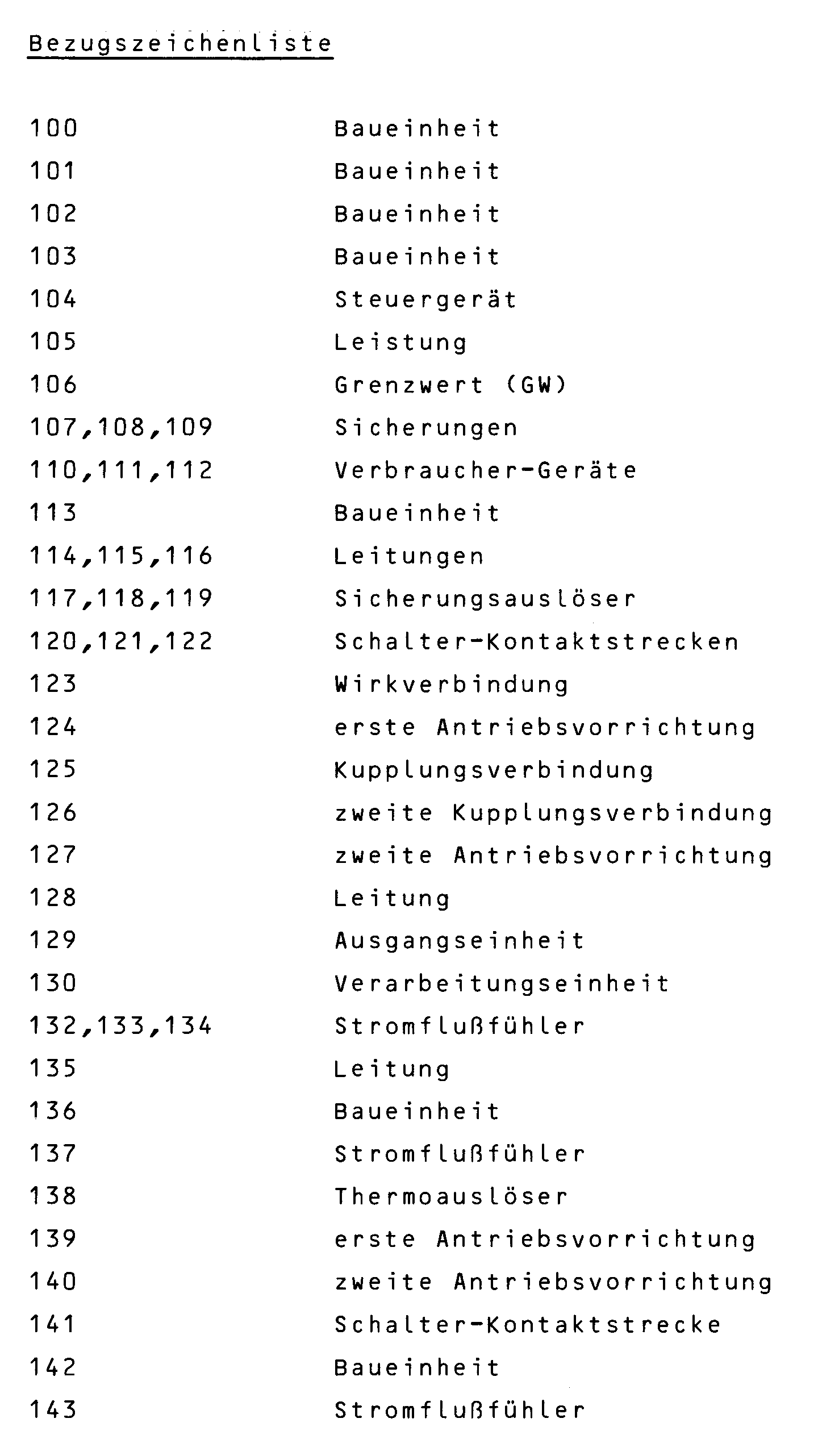


Claims (47)
dadurch gekennzeichnet,
bei einem auf dem Gesamt-Energieverbrauch (EV) in einem bestimmten aus einer Anzahl (N) von Intervallen (Z) einer Intervallbreite (TI) bestehenden Zeitabschnitt (TP) basierenden und so leistungsabhängigen Tarif der Grenzwert (GW) für ein folgendes Intervall (Z) aus dem Energieverbrauchs-Wert (E1,E2...) in wenigstens einem zurückliegenden Intervall (Z) mittels der Verarbeitungseinheit (130) nach einem vorgegebenen Programm ermittelt wird.Arrangement for controlling the total energy consumption (EV) of an electricity consumer, in which, in several circuits (114, 115, 116) for each consumer device (110, 111, 112) in addition to an overload switch (117, 118, 119, 124), both a controllable switch (120, 121, 122, 127) and one each a current flow sensor providing current flow sensors (132, 133, 134) are switched on and in which the current flow signals, possibly via intermediate stages such as amplifiers, are fed to a processing unit (130) (computer), a sum signal preferably being formed from the current flow signals and the controllable switches are connected to the processing unit (130) in such a way that at least one of the switches is actuated and the associated circuit is interrupted when the sum signal exceeds a limit value,
characterized,
in the case of a tariff (GW) based on the total energy consumption (EV) in a specific time period (TP) consisting of a number (N) of intervals (Z) of an interval width (TI) and thus performance-dependent, the limit value (GW) for a subsequent interval (Z ) is determined from the energy consumption value (E1, E2 ...) in at least one previous interval (Z) by means of the processing unit (130) according to a predetermined program.
dadurch gekennzeichnet,
daß der Gesamt-Energieverbrauch (EV) in einem Zeitabschnitt (TP) von festgelegter Dauer einem gegebenen Energie-Sollwert (EP) entsprechen und ihn nicht überschreiten soll,
daß der Zeitabschnitt (TP) in N, vorzugsweise gleich große, Intervalle (Z) von der Breite (TI) unterteilt ist, wobei (Z) die Intervallnummer bezeichnet, die mit der Zeit (t) von Intervall zu Intervall kontinuierlich ansteigt,
daß der Energieverbrauch (EZ) in jedem Intervall (Z) gemessen und über die letzten (N-1) Intervalle summiert wird zu einem Summenwert (ES), der vom Energie-Sollwert (EP) für den ganzen Zeitabschnitt (TP) abgezogen und so ein Differenzwert DE = (EP - ES) gebildet wird, mit dem der Grenzwert (GW) im nachfolgenden N-ten Intervall bestimmt wird.Arrangement according to claim 1,
characterized,
that the total energy consumption (EV) in a time period (TP) of a fixed duration corresponds to a given energy setpoint (EP) and should not exceed it,
that the time period (TP) is divided into N, preferably equally large, intervals (Z) by the width (TI), where (Z) denotes the interval number that increases continuously with time (t) from interval to interval,
that the energy consumption (EZ) is measured in each interval (Z) and summed over the last (N-1) intervals to a total value (ES), which is subtracted from the energy setpoint (EP) for the entire period (TP) and so a difference value DE = (EP - ES) is formed, with which the limit value (GW) is determined in the subsequent Nth interval.
dadurch gekennzeichnet,
daß der Summenwert (ES) vom Strom abhängig ist.Arrangement according to claim 1 or 2,
characterized,
that the total value (ES) depends on the current.
dadurch gekennzeichnet,
daß der Summenwert (ES) von der zugeführten Blindleistung abhängig ist.Arrangement according to claim 1 or 2,
characterized,
that the total value (ES) depends on the reactive power supplied.
dadurch gekennzeichnet,
daß der Summenwert (ES) von der zugeführten Wirkleistung abhängig ist.Arrangement according to claim 1 or 2,
characterized,
that the total value (ES) depends on the active power supplied.
dadurch gekennzeichnet,
daß die vom Anfang des nachfolgenden (N-ten) Intervalles ab verbrauchte Energie laufend gemessen und der zugehörige Grenzwert (GW) entsprechend der bis zum Ende des (N-ten) Intervalles noch verbrauchbaren Energie abfallend verändert wird.Arrangement according to one of the preceding claims,
characterized,
that the energy consumed from the beginning of the subsequent (Nth) interval is continuously measured and the associated limit value (GW) is changed in a decreasing manner in accordance with the energy still consumable until the end of the (Nth) interval.
dadurch gekennzeichnet,
daß der Grenzwert (GW) in mehreren Stufen von z.B. zuerst 15 und zuletzt 5 Minuten Dauer abfallend verändert wird.Arrangement according to claim 6,
characterized,
that the limit value (GW) is changed in several stages, for example first 15 and last 5 minutes.
dadurch gekennzeichnet,
daß die vom Anfang des nachfolgenden (N-ten) Intervalles ab verbrauchte Energie laufend gemessen wird und erst bei Annäherung an den Energiesollwert (EP) der Grenzwert wirksam gemacht wird und erforderlichenfalls die aufgenommene Leistung (L; Kurve 105) mittels der steuerbaren Schalter selbsttätig reduziert wird.Arrangement according to one of claims 1 to 5,
characterized,
that the energy consumed from the beginning of the subsequent (Nth) interval is measured continuously and the limit value is only activated when the energy setpoint (EP) is approached and, if necessary, the power consumed (L; curve 105) is reduced automatically by means of the controllable switches becomes.
dadurch gekennzeichnet,
daß die vom Anfang eines nachfolgenden (N-ten) Intervalles ab verbrauchte Energie laufend gemessen und bei Annäherung an eine am Ende des (N-ten) Intervalles zum Energiesollwert (EP) hin verlaufende Grenzwertkurve minimalen Verbrauches erforderlichenfalls die aufgenommene Leistung (L; Kurve 105) mittels der steuerbaren Schalter selbsttätig reduziert wird.Arrangement according to claim 1 to 5,
characterized,
that the energy consumed from the beginning of a subsequent (Nth) interval is measured continuously and, when approaching a limit curve of minimum consumption running towards the energy setpoint (EP) at the end of the (Nth) interval, the power consumed if necessary (L; curve 105 ) is automatically reduced by means of the controllable switches.
dadurch gekennzeichnet,
daß im Falle der Überschreitung des Grenzwertes (GW) durch den momentanen Energieverbrauch (LZ) wenigstens eines der angeschalteten Geräte (110,111,112,241,147, 148,152) entsprechend einer bestimmten Rangfolge im Verbrauch reduziert bzw. ganz oder teilweise abgeschaltet wird oder im Falle eines Unterschreitens des Grenzwertes (GW) um mehr als einen vorgegebenen Schwellwert (SW) ganz oder teilweise eingeschaltet wird.Arrangement according to one of the preceding claims,
characterized,
that if the limit value (GW) is exceeded due to the current energy consumption (LZ), at least one of the connected devices (110, 111, 112, 241, 148, 152) is reduced or completely or partially switched off in accordance with a certain order of priority, or if the limit value (GW ) is switched on in whole or in part by more than a predetermined threshold value (SW).
dadurch gekennzeichnet,
daß beim Unterschreiten des Grenzwertes (GW) zunächst wenigstens ein solches Verbraucher-Gerät (241,147,148) wieder eingeschaltet wird, das bei einem vorangehenden Abschalten im Verbrauch reduziert oder abgeschaltet wurde.Arrangement according to claim 10,
characterized,
that when the limit value (GW) is undershot, at least one such consumer device (241, 147, 148) is switched on again, which was reduced or switched off in the case of a previous shutdown.
dadurch gekennzeichnet,
daß wenigstens eines der Verbraucher-Geräte (141,147, 148) in Intervallen von z.B. einigen Sekunden oder Minuten Dauer periodisch eingeschaltet und abgeschaltet wird.Arrangement according to claim 11,
characterized,
that at least one of the consumer devices (141, 147, 148) is periodically switched on and off at intervals of, for example, a few seconds or minutes.
dadurch gekennzeichnet,
daß wenigstens eines der Verbraucher-Geräte (152) in Phasenanschnittsteuerung in jeder Wechselstromperiode eingeschaltet und abgeschaltet wird.Arrangement according to claim 11,
characterized,
that at least one of the consumer devices (152) is switched on and off in phase control in every AC period.
dadurch gekennzeichnet,
daß der Schwellwert (SW) für Verbrauchereinschaltung etwa einer Energieaufnahme von einem bestimmten Prozentsatz, z.B. 1 bis 3 %, der Grenzwert-Leistung entspricht.Arrangement according to claim 11, 12 or 13,
characterized,
that the threshold value (SW) for consumer activation corresponds approximately to an energy consumption of a certain percentage, for example 1 to 3%, of the limit value power.
dadurch gekennzeichnet,
daß der steuerbare Schalter, der Stromflußfühler und der Überlastungs-Schalter für einen Stromkreis zu einer Baueinheit (113) zusammengefaßt sind.Arrangement for controlling the total consumption of an electricity consumer, in which in several circuits (114, 115, 116) each have a consumer device (110, 111, 112) except for an overload switch (117, 118, 119, 124) both a controllable switch (120, 121, 122, 127) and a current flow sensor (132, 133, 134) providing a current flow signal are switched on, in particular according to one of the preceding claims,
characterized,
that the controllable switch, the current flow sensor and the overload switch for a circuit are combined to form a unit (113).
dadurch gekennzeichnet,
daß die Baueinheit (113) derart gestaltet ist, daß sie an der Stelle des auch bisher benötigten Sicherungselementes in der vorhandenen Elektroverteilung montierbar ist.Arrangement according to claim 15,
characterized,
that the structural unit (113) is designed such that it can be installed in the existing electrical distribution board at the location of the securing element that was previously required.
dadurch gekennzeichnet,
daß wenigstens ein den Stromkreis unterbrechender Schalter (193) einerseits zum Öffnen und zum Schließen von der Verarbeitungseinheit her steuerbar ist und andererseits bei Überlastung selbsttätig geöffnet wird, aber nur von Hand wieder schließbar ist. (Fig.4)Arrangement according to claim 15 or 16,
characterized,
that at least one switch (193) which interrupts the circuit can on the one hand be controlled by the processing unit for opening and closing and on the other hand can be opened automatically in the event of an overload, but can only be closed again by hand. (Fig.4)
dadurch gekennzeichnet,
daß zum Schalten des Stromkreises eine Kontaktstrecke (193) dient, die gekoppelt ist einerseits mit einer (zweiten) Antriebsvorrichtung (194), die von der Verarbeitungseinheit (130) her den Kontakt öffnend und schließend steuerbar ist, und andererseits mit einer (ersten) Antriebsvorrichtung (197), die beim Auftreten einer Überlastung im Stromkreis die Kontaktstrecke (193) öffnet und mittels einer Rastung (198;203 die nur von Hand in die Ausgangslage zurückgebracht werden kann.Arrangement according to claim 17,
characterized,
that serves to switch the circuit, a contact path (193) which is coupled on the one hand to a (second) drive device (194) which opens the contact from the processing unit (130) and can be closed, and on the other hand with a (first) drive device (197) which opens the contact path (193) when an overload occurs in the circuit and by means of a detent (198; 203 which can only be returned to the starting position by hand.
dadurch gekennzeichnet,
daß die Kontaktstrecke des nach dem Grenzwert (GW) steuerbaren Schalters (120,121,122) einen Ruhekontakt darstellt.Arrangement according to one of the preceding claims,
characterized,
that the contact distance of the switch (120, 121, 122) controllable according to the limit value (GW) represents a normally closed contact.
dadurch gekennzeichnet,
daß die Stromfluß-Signale der Verarbeitungseinheit (130) über Analog/Digital-Wandler zugeführt werden.Arrangement according to one of the preceding claims,
characterized,
that the current flow signals are fed to the processing unit (130) via analog / digital converters.
dadurch gekennzeichnet,
daß die A/D-Wandler in der Eingangsstufe (159) enthalten sind.Arrangement according to claim 20,
characterized,
that the A / D converters are included in the input stage (159).
dadurch gekennzeichnet,
daß die A/D-Wandler in der Nähe der Stromflußfühler (132,133,134) angebracht sind.Arrangement according to one of the preceding claims 1 to 20,
characterized,
that the A / D converters are installed near the current flow sensors (132, 133, 134).
dadurch gekennzeichnet,
daß für Drehstromverbraucher an jede Phasenleitung ein Stromflußfühler (132,133,134) angekoppelt ist, deren Signale zusammengefaßt das Summensignal bilden.Arrangement according to one of the preceding claims,
characterized,
that for three-phase consumers, a current flow sensor (132, 133, 134) is coupled to each phase line, the signals of which form the sum signal.
dadurch gekennzeichnet,
daß die in jeder der drei Leitungen angeordneten Schalter (120,121,122) gleichzeitig geöffnet bzw. geschlossen werden.Arrangement according to claim 23,
characterized,
that the switches (120, 121, 122) arranged in each of the three lines are opened or closed simultaneously.
dadurch gekennzeichnet,
daß die Verarbeitungseinheit (130) die Programmstufe (171), die Eingangsstufe (159), die Ausgangsstufe (129) und/oder die Grenzwertstufe (162) sowie ggf. erforderliche weitere Stufen wie Speicher und Speiseschaltungen in einem Steuergerät (104) zusammengefaßt sind.Arrangement according to one of the preceding claims,
characterized,
that the processing unit (130), the program stage (171), the input stage (159), the output stage (129) and / or the limit stage (162) and any other stages such as memory and supply circuits that may be required are combined in a control unit (104).
dadurch gekennzeichnet,
daß die Verbindungen von den Stromflußfühlern (132,133,134) zur Eingangsstufe (159) über flexible Kabel, vorzugsweise mit Steckeranschluß, vorgenommen sind.Arrangement according to claim 25,
characterized,
that the connections from the current flow sensors (132, 133, 134) to the input stage (159) are made via flexible cables, preferably with a plug connection.
dadurch gekennzeichnet,
daß die Verbindung von der Ausgangseinheit (129) zu den Antriebsvorrichtungen (127) der steuerbaren Schalter (120,121,122) über flexible Kabel, vorzugsweise mit Steckeranschluß, vorgenommen sind.Arrangement according to one of the preceding claims,
characterized,
that the connection from the output unit (129) to the drive devices (127) of the controllable switches (120, 121, 122) is made via flexible cables, preferably with a plug connection.
dadurch gekennzeichnet,
daß die das Programm für die Verarbeitungseinheit (130) liefernde Programmstufe (171) nachträglich einstellbar ist.Arrangement according to one of the preceding claims,
characterized,
that the program stage (171) delivering the program for the processing unit (130) can be subsequently adjusted.
dadurch gekennzeichnet,
daß die Einstellung mittels einer Tastatur (174) durchführbar ist.Arrangement according to claim 28,
characterized,
that the setting can be carried out using a keyboard (174).
dadurch gekennzeichnet,
daß die Einstellung mittels einer von einer Magnetkarte (176) steuerbaren Leseeinrichtung (175) durchführbar ist.Arrangement according to claim 28 or 29,
characterized,
that the setting can be carried out by means of a reading device (175) which can be controlled by a magnetic card (176).
dadurch gekennzeichnet,
daß Vorrang bzw. Nachrang für die Schalterbetätigung nachträglich veränderbar ist.Arrangement according to one of the preceding claims,
characterized,
that priority or subordination for the switch actuation can be changed later.
dadurch gekennzeichnet,
daß der steuerbare Schalter elektronisch, z.B. als Thyristor (153), betätigbar ist.Arrangement according to one of the preceding claims,
characterized,
that the controllable switch can be actuated electronically, for example as a thyristor (153).
dadurch gekennzeichnet,
daß einzelne Verbraucher (241,147,148) periodisch abwechselnd aus- bzw. einschaltbar sind.Arrangement according to one of the preceding claims,
characterized,
that individual consumers (241, 147, 148) can be periodically switched on and off alternately.
dadurch gekennzeichnet,
daß Einschaltverriegelungen zwischen beliebigen Verbraucher-Geräten durchführbar sind.Arrangement according to one of the preceding claims,
characterized,
that power-on interlocks can be carried out between any consumer devices.
dadurch gekennzeichnet,
daß der Schaltzustand wenigstens eines Schalters (141,146) optisch angezeigt wird.Arrangement according to one of the preceding claims,
characterized,
that the switching state of at least one switch (141, 146) is displayed optically.
dadurch gekennzeichnet,
daß eine Anzeigefläche (187), insbesondere am Steuergerät (104), angebracht ist.Arrangement according to claim 35,
characterized,
that a display surface (187), in particular on the control unit (104), is attached.
dadurch gekennzeichnet,
daß die Schaltzustände "stromführend", "bereit für Stromführung", "nicht bereit für Stromführung" angezeigt werden.Arrangement according to claim 35 or 36,
characterized,
that the switching states "live", "ready for current", "not ready for current" are displayed.
dadurch gekennzeichnet,
daß eine Anzeigefläche an wenigstens einem der Verbraucher-Geräte (241,147,148) angebracht ist.Arrangement according to one of claims 35, 36 or 37,
characterized,
that a display surface is attached to at least one of the consumer devices (241, 147, 148).
dadurch gekennzeichnet,
daß der Verarbeitungseinheit (130) wenigstens ein Tageszeitsignal, ein Wochentagssignal und/oder ein Jahreszeitsignal zuführbar ist.Arrangement according to one of the preceding claims,
characterized,
that the processing unit (130) can be supplied with at least one time of day signal, a weekday signal and / or a season signal.
dadurch gekennzeichnet,
daß der Verarbeitungseinheit (130) wenigstens ein Signal von außen, vorzugsweise über Optokoppler, zuführbar ist.Arrangement according to one of the preceding claims,
characterized,
that the processing unit (130) can be supplied with at least one signal from the outside, preferably via optocouplers.
dadurch gekennzeichnet,
daß externe Steuersignale, z.B. für die Zählereinstellung, Rundsteuerimpulse od.dgl. vom EVU zuführbar (178) sind.Arrangement according to claim 40,
characterized,
that external control signals, for example for setting the counter, ripple control pulses or the like. can be supplied by the power supply company (178).
dadurch gekennzeichnet,
daß an die Verarbeitungseinheit (130) ein Elektrizitätszähler (184) angeschlossen ist.Arrangement according to one of the preceding claims,
characterized,
that an electricity meter (184) is connected to the processing unit (130).
dadurch gekennzeichnet,
daß alle Anordnungsteile zusammen an einer Schalttafel angebracht sind.Arrangement according to one of the preceding claims,
characterized,
that all arrangement parts are attached together on a control panel.
dadurch gekennzeichnet,
daß die Anordnungsteile gegeneinander abgeschirmt sind.Arrangement according to one of the preceding claims,
characterized,
that the arrangement parts are shielded from each other.
dadurch gekennzeichnet,
daß Stromflußfühler (z.B. 137) und steuerbarer Schalter (z.B. 141) an der Schalttafel angebracht sind, die weiteren Anordnungsteile jedoch entfernt davon, z.B. in einem Steuergerät (140), angeordnet sind.Arrangement according to one of the preceding claims,
characterized,
that current flow sensors (for example 137) and controllable switches (for example 141) are attached to the control panel, but the other parts of the arrangement are arranged away therefrom, for example in a control unit (140).
dadurch gekennzeichnet,
daß der zulässige Sollwert (SW) vom Elektrizitäts-Abnehmer auf begrenzte Zeit geändert, vorzugsweise angehoben werden kann.Arrangement according to one of the preceding claims,
characterized,
that the permissible setpoint (SW) can be changed, preferably increased, by the electricity consumer for a limited time.
dadurch gekennzeichnet,
daß an die Verarbeitungsstufe ein, ggf. registrierender, Maximum-Wächter angeschaltet ist.Arrangement according to one of the preceding claims,
characterized,
that a, possibly registering, maximum guardian is switched on at the processing stage.
Applications Claiming Priority (2)
| Application Number | Priority Date | Filing Date | Title |
|---|---|---|---|
| DE4019523 | 1990-06-19 | ||
| DE4019523A DE4019523A1 (en) | 1990-06-19 | 1990-06-19 | ARRANGEMENT FOR CONTROLLING THE POWER CONSUMPTION OF A CUSTOMER |
Publications (2)
| Publication Number | Publication Date |
|---|---|
| EP0464423A1 true EP0464423A1 (en) | 1992-01-08 |
| EP0464423B1 EP0464423B1 (en) | 1994-10-26 |
Family
ID=6408665
Family Applications (1)
| Application Number | Title | Priority Date | Filing Date |
|---|---|---|---|
| EP91109755A Expired - Lifetime EP0464423B1 (en) | 1990-06-19 | 1991-06-14 | Device for controlling the total energy-consumption of an electricity consumer |
Country Status (4)
| Country | Link |
|---|---|
| EP (1) | EP0464423B1 (en) |
| AT (1) | ATE113422T1 (en) |
| DE (2) | DE4019523A1 (en) |
| ES (1) | ES2064811T3 (en) |
Cited By (4)
| Publication number | Priority date | Publication date | Assignee | Title |
|---|---|---|---|---|
| EP0561255A1 (en) * | 1992-03-10 | 1993-09-22 | Mitsubishi Denki Kabushiki Kaisha | Demand control apparatus and power distribution control system |
| FR2719440A1 (en) * | 1994-04-28 | 1995-11-03 | Delta Dore | Electrical installation control appts. in single dwelling |
| DE10064165A1 (en) * | 2000-12-22 | 2002-06-27 | Dieter Steinigeweg | Method for monitoring and controlling energy use of a group of individually switched energy loads, particularly electrical appliances within a household to help in minimizing energy use |
| EP1952292A2 (en) * | 2005-11-25 | 2008-08-06 | Computerized Electricity Systems Ltd. | Flexible electric load management system and method therefor |
Families Citing this family (5)
| Publication number | Priority date | Publication date | Assignee | Title |
|---|---|---|---|---|
| DE19703944A1 (en) * | 1997-02-03 | 1998-08-20 | Gerd Bajog | Programmable operational control for consumers drawing on water- or current-mains e.g. for washing machine |
| DE19827345B4 (en) * | 1998-06-19 | 2005-04-14 | Fünfgeld, Christian, Dipl.-Ing. | Method for deriving the active power of electrical consumers |
| DE10034684A1 (en) * | 2000-07-17 | 2002-01-31 | Endress Hauser Gmbh Co | Measuring device for measuring a process variable |
| DE10039231A1 (en) * | 2000-08-11 | 2002-02-28 | Werner Schmidt | Electrical installation for building, has computer which controls or monitors switch member based on measured current values or time program |
| DE102016212494A1 (en) | 2016-07-08 | 2018-01-11 | Siemens Aktiengesellschaft | Method and device for monitoring an energy supply device of a traffic engineering system |
Citations (3)
| Publication number | Priority date | Publication date | Assignee | Title |
|---|---|---|---|---|
| US4059747A (en) * | 1976-06-08 | 1977-11-22 | Brody Mitchell D | Demand controller |
| EP0003010A1 (en) * | 1977-12-27 | 1979-07-11 | United Technologies Corporation | Method and apparatus for limiting the power demand in heating-ventilation-air conditioning |
| WO1990006612A1 (en) * | 1988-11-29 | 1990-06-14 | Engego Ab | A method for supplying electricity |
Family Cites Families (3)
| Publication number | Priority date | Publication date | Assignee | Title |
|---|---|---|---|---|
| DE1588439B1 (en) * | 1967-04-26 | 1971-05-13 | Hartmann & Braun Ag | SELECTOR FOR MAXIMUM LOAD MONITORING |
| DE3226544A1 (en) * | 1982-07-15 | 1984-01-19 | Siemens AG, 1000 Berlin und 8000 München | SYSTEM FOR CONTROLLING THE ELECTRICAL ENERGY CONSUMPTION, PREFERABLY IN HOUSEHOLD |
| DE3701493A1 (en) * | 1987-01-20 | 1988-07-28 | Nixdorf Computer Ag | CIRCUIT ARRANGEMENT FOR DISTRIBUTING ELECTRICAL POWER TO MULTIPLE FUNCTIONAL UNITS |
-
1990
- 1990-06-19 DE DE4019523A patent/DE4019523A1/en active Granted
-
1991
- 1991-06-14 EP EP91109755A patent/EP0464423B1/en not_active Expired - Lifetime
- 1991-06-14 AT AT91109755T patent/ATE113422T1/en not_active IP Right Cessation
- 1991-06-14 ES ES91109755T patent/ES2064811T3/en not_active Expired - Lifetime
- 1991-06-14 DE DE59103323T patent/DE59103323D1/en not_active Expired - Fee Related
Patent Citations (3)
| Publication number | Priority date | Publication date | Assignee | Title |
|---|---|---|---|---|
| US4059747A (en) * | 1976-06-08 | 1977-11-22 | Brody Mitchell D | Demand controller |
| EP0003010A1 (en) * | 1977-12-27 | 1979-07-11 | United Technologies Corporation | Method and apparatus for limiting the power demand in heating-ventilation-air conditioning |
| WO1990006612A1 (en) * | 1988-11-29 | 1990-06-14 | Engego Ab | A method for supplying electricity |
Cited By (6)
| Publication number | Priority date | Publication date | Assignee | Title |
|---|---|---|---|---|
| EP0561255A1 (en) * | 1992-03-10 | 1993-09-22 | Mitsubishi Denki Kabushiki Kaisha | Demand control apparatus and power distribution control system |
| EP1330007A3 (en) * | 1992-03-10 | 2005-11-30 | Mitsubishi Denki Kabushiki Kaisha | Demand control apparatus and power distribution control system |
| FR2719440A1 (en) * | 1994-04-28 | 1995-11-03 | Delta Dore | Electrical installation control appts. in single dwelling |
| DE10064165A1 (en) * | 2000-12-22 | 2002-06-27 | Dieter Steinigeweg | Method for monitoring and controlling energy use of a group of individually switched energy loads, particularly electrical appliances within a household to help in minimizing energy use |
| EP1952292A2 (en) * | 2005-11-25 | 2008-08-06 | Computerized Electricity Systems Ltd. | Flexible electric load management system and method therefor |
| EP1952292A4 (en) * | 2005-11-25 | 2014-03-05 | Computerized Electricity Systems Ltd | Flexible electric load management system and method therefor |
Also Published As
| Publication number | Publication date |
|---|---|
| ATE113422T1 (en) | 1994-11-15 |
| EP0464423B1 (en) | 1994-10-26 |
| DE4019523C2 (en) | 1992-06-11 |
| DE59103323D1 (en) | 1994-12-01 |
| ES2064811T3 (en) | 1995-02-01 |
| DE4019523A1 (en) | 1992-01-09 |
Similar Documents
| Publication | Publication Date | Title |
|---|---|---|
| EP0648005B1 (en) | Apparatus for limiting the power consumption of a household supplied by a power supply connection | |
| EP0225657B1 (en) | Method for controlling several electrical loads | |
| DE60036150T2 (en) | Method for operating a power supply system with parallel-connected inverters and current transformer system | |
| DE3781211T2 (en) | POWER ADJUSTMENT DEVICE FOR ELECTRICAL SYSTEM, ESPECIALLY HOUSING SYSTEM WITH CARRIER FREQUENCY CONTROL. | |
| EP0053383B1 (en) | Process for computerized supervision of the total consumption of a group of electricity consumers | |
| EP2589125A1 (en) | Switching on end devices according to network load | |
| DE2804965A1 (en) | DEVICE AND METHOD FOR LIMITING ENERGY CONSUMPTION | |
| EP0464423B1 (en) | Device for controlling the total energy-consumption of an electricity consumer | |
| EP2692037B1 (en) | Control apparatus for an electrical load | |
| DE3226544A1 (en) | SYSTEM FOR CONTROLLING THE ELECTRICAL ENERGY CONSUMPTION, PREFERABLY IN HOUSEHOLD | |
| DE19842043B4 (en) | A method for automatically and consumer-oriented minimization of the total power consumption and peak power of a group of individual electrical consumers connected to a power supply network | |
| DE68923817T2 (en) | Power setting device for electrical power systems, in particular for electrical power systems with electric cookers. | |
| EP0828406B1 (en) | Device for limiting and distributing the electric power used by a cooking hob | |
| DE3426542C2 (en) | ||
| DE2419663C3 (en) | Device for coordinating and switching the energy requirements of several electrical consumers that work independently of one another | |
| DE19600188A1 (en) | Influencing instantaneous power relationship of individual user of user group | |
| DE2316341A1 (en) | PROCESS FOR CONTINUOUSLY DISTRIBUTING ELECTRIC ENERGY | |
| EP3297115B1 (en) | Assembly with an energy storage device and energy converter for absorbing electrical energy from a power network and discharge of electrical energy to the power network | |
| DE19651484A1 (en) | Power consumption optimising method for system of electrically heated and cooled loads esp. for industrial applications | |
| DE19900185A1 (en) | Method and device for switching consumers of an electrical device | |
| DE2019020B2 (en) | Procedure for changing a consumer's service receipt | |
| EP3369289B1 (en) | Method to control a cooking device, cooking device and heating element | |
| EP0254098A1 (en) | Method for regulating the bulk of energy of a user comprising several consumers | |
| EP1067650B1 (en) | Control arrangement For the distribution of electric power and method of operation | |
| AT520507B1 (en) | Procedure for minimizing the performance-dependent cost components of the electricity bill while at the same time optimizing the performance target value |
Legal Events
| Date | Code | Title | Description |
|---|---|---|---|
| PUAI | Public reference made under article 153(3) epc to a published international application that has entered the european phase |
Free format text: ORIGINAL CODE: 0009012 |
|
| AK | Designated contracting states |
Kind code of ref document: A1 Designated state(s): AT BE CH DE DK ES FR GB GR IT LI LU NL SE |
|
| 17P | Request for examination filed |
Effective date: 19920205 |
|
| 17Q | First examination report despatched |
Effective date: 19921217 |
|
| GRAA | (expected) grant |
Free format text: ORIGINAL CODE: 0009210 |
|
| ITF | It: translation for a ep patent filed | ||
| AK | Designated contracting states |
Kind code of ref document: B1 Designated state(s): AT BE CH DE DK ES FR GB GR IT LI LU NL SE |
|
| PG25 | Lapsed in a contracting state [announced via postgrant information from national office to epo] |
Ref country code: GR Free format text: LAPSE BECAUSE OF FAILURE TO SUBMIT A TRANSLATION OF THE DESCRIPTION OR TO PAY THE FEE WITHIN THE PRESCRIBED TIME-LIMIT Effective date: 19941026 |
|
| REF | Corresponds to: |
Ref document number: 113422 Country of ref document: AT Date of ref document: 19941115 Kind code of ref document: T |
|
| REF | Corresponds to: |
Ref document number: 59103323 Country of ref document: DE Date of ref document: 19941201 |
|
| GBT | Gb: translation of ep patent filed (gb section 77(6)(a)/1977) |
Effective date: 19941104 |
|
| ET | Fr: translation filed | ||
| EAL | Se: european patent in force in sweden |
Ref document number: 91109755.8 |
|
| REG | Reference to a national code |
Ref country code: ES Ref legal event code: FG2A Ref document number: 2064811 Country of ref document: ES Kind code of ref document: T3 |
|
| REG | Reference to a national code |
Ref country code: GR Ref legal event code: FG4A Free format text: 3014858 |
|
| PG25 | Lapsed in a contracting state [announced via postgrant information from national office to epo] |
Ref country code: GB Effective date: 19950614 Ref country code: DK Effective date: 19950614 |
|
| PG25 | Lapsed in a contracting state [announced via postgrant information from national office to epo] |
Ref country code: SE Effective date: 19950615 Ref country code: ES Free format text: LAPSE BECAUSE OF THE APPLICANT RENOUNCES Effective date: 19950615 |
|
| PG25 | Lapsed in a contracting state [announced via postgrant information from national office to epo] |
Ref country code: LU Free format text: LAPSE BECAUSE OF NON-PAYMENT OF DUE FEES Effective date: 19950630 Ref country code: BE Effective date: 19950630 |
|
| PLBE | No opposition filed within time limit |
Free format text: ORIGINAL CODE: 0009261 |
|
| STAA | Information on the status of an ep patent application or granted ep patent |
Free format text: STATUS: NO OPPOSITION FILED WITHIN TIME LIMIT |
|
| 26N | No opposition filed | ||
| PGFP | Annual fee paid to national office [announced via postgrant information from national office to epo] |
Ref country code: FR Payment date: 19951130 Year of fee payment: 5 |
|
| PGFP | Annual fee paid to national office [announced via postgrant information from national office to epo] |
Ref country code: CH Payment date: 19951218 Year of fee payment: 5 |
|
| PGFP | Annual fee paid to national office [announced via postgrant information from national office to epo] |
Ref country code: AT Payment date: 19951229 Year of fee payment: 5 |
|
| BERE | Be: lapsed |
Owner name: DECHER DIETER Effective date: 19950630 |
|
| PG25 | Lapsed in a contracting state [announced via postgrant information from national office to epo] |
Ref country code: NL Effective date: 19960101 |
|
| GBPC | Gb: european patent ceased through non-payment of renewal fee |
Effective date: 19950614 |
|
| REG | Reference to a national code |
Ref country code: GR Ref legal event code: MM2A Free format text: 3014858 |
|
| NLV4 | Nl: lapsed or anulled due to non-payment of the annual fee |
Effective date: 19960101 |
|
| EUG | Se: european patent has lapsed |
Ref document number: 91109755.8 |
|
| PG25 | Lapsed in a contracting state [announced via postgrant information from national office to epo] |
Ref country code: AT Effective date: 19960614 |
|
| PG25 | Lapsed in a contracting state [announced via postgrant information from national office to epo] |
Ref country code: LI Effective date: 19960630 Ref country code: CH Effective date: 19960630 |
|
| REG | Reference to a national code |
Ref country code: CH Ref legal event code: PL |
|
| PG25 | Lapsed in a contracting state [announced via postgrant information from national office to epo] |
Ref country code: FR Effective date: 19970228 |
|
| REG | Reference to a national code |
Ref country code: FR Ref legal event code: ST |
|
| REG | Reference to a national code |
Ref country code: ES Ref legal event code: FD2A Effective date: 19991007 |
|
| PGFP | Annual fee paid to national office [announced via postgrant information from national office to epo] |
Ref country code: DE Payment date: 20000425 Year of fee payment: 9 |
|
| PG25 | Lapsed in a contracting state [announced via postgrant information from national office to epo] |
Ref country code: DE Free format text: LAPSE BECAUSE OF NON-PAYMENT OF DUE FEES Effective date: 20010403 |
|
| PG25 | Lapsed in a contracting state [announced via postgrant information from national office to epo] |
Ref country code: IT Free format text: LAPSE BECAUSE OF NON-PAYMENT OF DUE FEES Effective date: 20050614 |