EP0463735A2 - Piezo electric resonator temperature sensor - Google Patents
Piezo electric resonator temperature sensor Download PDFInfo
- Publication number
- EP0463735A2 EP0463735A2 EP91304778A EP91304778A EP0463735A2 EP 0463735 A2 EP0463735 A2 EP 0463735A2 EP 91304778 A EP91304778 A EP 91304778A EP 91304778 A EP91304778 A EP 91304778A EP 0463735 A2 EP0463735 A2 EP 0463735A2
- Authority
- EP
- European Patent Office
- Prior art keywords
- frequency
- resonator
- vibrations
- temperature
- overtone
- Prior art date
- Legal status (The legal status is an assumption and is not a legal conclusion. Google has not performed a legal analysis and makes no representation as to the accuracy of the status listed.)
- Granted
Links
Images


Classifications
-
- G—PHYSICS
- G01—MEASURING; TESTING
- G01K—MEASURING TEMPERATURE; MEASURING QUANTITY OF HEAT; THERMALLY-SENSITIVE ELEMENTS NOT OTHERWISE PROVIDED FOR
- G01K7/00—Measuring temperature based on the use of electric or magnetic elements directly sensitive to heat ; Power supply therefor, e.g. using thermoelectric elements
- G01K7/32—Measuring temperature based on the use of electric or magnetic elements directly sensitive to heat ; Power supply therefor, e.g. using thermoelectric elements using change of resonant frequency of a crystal
Definitions
- This invention relates to temperature measurement, and in particular to a method and apparatus for determining the temperature of a piezo-electric crystal oscillator.
- Piezo-electric e.g.quartz crystal
- oscillators or resonators are widely used as frequency standards, e.g.for frequency synthesis applications. Whilst the frequency response of a quartz device to temperature changes is relatively small, it is significant in close tolerance applications and must therefore be compensated for by the derivation of an error signal.
- a preferred approach to this problem is to employ the quartz crystal itself as a temperature sensor. It has been found that some harmonics have a larger frequency response to temperature than others.
- a further approach is to employ harmonics of two different modal classes.
- This technique is described for example in US patent No. 4,468,634 which teaches the use of a tuning fork resonator which vibrates in both a torsioned and a flexural mode. The frequency difference between these two modes is temperature sensitive and thus provides a measure of the crystal temperature.
- the technique places severe constraints on the resonator design.
- Other workers have proposed the use of a B-mode harmonic together with a C-mode harmonic. This can in principle provide accurate temperature measurement. However, it has been found, in crystal cuts where the C-mode is relatively stable, that it is almost impossible to avoid completely coupling between the B-mode and flexural modes. Hence, at certain temperatures, the B-mode exhibits significant distortion in its temperature response. Further, the frequency of the B-mode oscillator has been found to be sensitive to stress associated with the rate of temperature change thus introducing further inaccuracy.
- An object of the present invention is to minimise or to overcome these disadvantages.
- a further object of the invention is to provide a piezoelectric resonator temperature sensor having a high accuracy and exhibiting stable operation.
- a method of determining the temperature of a piezo-electric resonator including comparing first and second inharmonically related vibrations of the same vibrational type and overtone order and of similar frequency whereby to derive a signal indicative of the oscillator temperature.
- a temperature compensated piezo-electric resonator including means for exciting first and second inharmonically related vibrations of a thickness shear mode of the same vibrational type and overtone order and of similar frequency, and means for deriving by comparison of the inharmonic vibrations, a signal characteristic of the temperature of the resonator.
- a frequency synthesiser including a piezo-electric resonator, means for deriving submultiples of the resonator frequency, means controlled by a synthesis algorithm for combining selected submultiple frequencies to provide an output synthesised frequency, means for exciting in said resonator first and second inharmonically related vibrations of a thickness shear mode of the same overtone order and of similar frequency, means for deriving, by comparison of the inharmonic vibrations, a signal corresponding to the temperature of the resonator, and means responsive to the temperature signal for adjusting the synthesis algorithm whereby to maintain the synthesised frequency at a constant value.
- the two oscillations are referred to as inharmonically related signals.
- the higher frequency exceeds the lower frequency by less than 5% and preferably by 2% or less.
- neither frequency is a simple multiple or or a simple rational faction of the other.
- the inharmonic signals are of similar frequency and vibrational type, the effects e.g. of mode trapping are similar so that a compact crystal design can provide good performance in both inharmonic modes.
- the selection between the modes can be determined by the use of appropriate electrode structures and by controlling the driving phase of the oscillation maintaining amplifier thus eliminating problems arising from the use of different frequency selective elements.
- the inharmonic vibrations are closely spaced in frequency and of similar type, they will be similarly affected by radiation and other environmental constraints.
- the technique is of particular application to temperature compensation of crystal oscillators using frequency synthesis techniques.
- the resonator comprises a generally lenticular quartz body 11 provided with metal, e.g. nichrome/gold, electrodes 13, 14 and 15.
- metal e.g. nichrome/gold
- SC-cut crystal is employed.
- mutually perpendicular vectors i, j, and k are shown defining three spatial reference directions.
- suitable crystal cuts include the AT and BT cuts.
- the crystal may be planar on one face, or may have both faces contoured.
- the electrodes 13, 14 and 15 are so disposed on the resonator surface as to generate a pair of similar frequency C-mode oscillations generally indicated by the arrows X and Y. These arrows indicate the local displacements corresponding to the two harmonic modes at an instant in time for the (n, 2, l) and (n, l, l) modes respectively.
- n is an odd integer.
- the vibrations are excited via an electrode structure which allows preferential coupling by different oscillators to different inharmonic modes thereby avoiding the requirement for narrow band frequency selection or trapping in the oscillation maintaining amplifier.
- the electrode arrangement shown in Figs 1 and 2 is suitable for an SC cut crystal.
- an electrode arrangement similar to that of a monolithic dual crystal filter would be more appropriate.
- the modes are excited by the application of appropriate potentials to the electrodes.
- an SC cut crystal for example, application of an electric field between the outer electrodes 13 and 15, with the central electrode driven at a potential which is midway between the outer electrode potentials, will excite preferentially an (n,l,l) mode.
- a circuit for providing such potential conditions is shown in Fig. 3.
- the circuit outputs 33, 34 and 35 are coupled to the electrodes 13, 14 and 15 respectively.
- Figure 4 shows an alternative circuit for exciting preferentially an (n,2,l) mode or an (n,l,2) mode, the particular mode being determined by the crystal orientation.
- This circuit applies identical potentials, via outputs 43 and 45 to electrodes 13 and 15 and applies further potentials, via output 44, to electrode 14.
- circuits of Figs 3 and 4 may be used simultaneously as each has only an insignificant effect on the other.
- Each mode is defined by a three digit characteristic of the form (n, a, b) wherein:-
- n is an integer, including unity.
- n 3.
- Figs. 5 and 6 illustrate the spatial distribution of the amplitudes of vibrational inharmonic modes for a 4 dioptre crystal element.
- the curves show the spatial distribution of the inharmonic vibrations relative to the distance from the crystal centre along the i and j directions defined above.
- Fig. 5 illustrates an arrangement in which not all the modal energies are trapped within a 5mm radius circle. It is preferred to employ an arrangement in which substantially all the modal energy is confined so as to avoid disturbance of the temperature/frequency response of the modes. In said circumstances a steeper crystal contour can be employed to reduce modal spreading.
- Fig. 7 there is shown a schematic diagram of a frequency synthesiser incorporating a temperature controlled crystal oscillator. It will be appreciated that this circuit is described by way of example only and is not specific to the particular crystal constructions detailed above.
- the synthesiser includes a reference piezo-electric resonator 51 driven by associated oscillator circuits 52 and one of whose output is fed to frequency divider circuits 53 the outputs of which are mixed via mixer 54.
- a control circuit 55 determines the particular subdivided frequencies to be mixed at any instant in accordance with a stored division algorithm whereby to provide the desired synthesised output frequency.
- the output frequency of the synthesiser is provided with temperature compensation in the following manner. Signals corresponding to the two inharmonics are fed to respective first and second amplifiers 56, 57, the outputs of which are coupled to a mixer circuit 58.
- the mixer combines the two amplified signals to obtain a beat frequency corresponding to the frequency difference between the two inharmonics. As the frequency difference between the inharmonics is relatively small, this beat frequency is comparatively low.
- the output of the mixer is fed via a low pass filter 59, which removes the high frequency sum of the inharmonics to a frequency meter circuit 60. Nore that one of the original frequencies may be used as the reference for the frequency meter.
- the circuit 60 provides a frequency, and hence temperature, responsive signal to the control circuit 55 which in response to this input adjusts the division algorithm to compensate for the change in oscillator frequency so as to maintain the output synthesised frequency at a constant value.
- the frequency difference signal corresponding to temperature may be employed in a feedback signal to maintain the resonator at a constant temperature and thus at a constant frequency.
- the arrangement may be used as a thermometer.
Abstract
Description
- This invention relates to temperature measurement, and in particular to a method and apparatus for determining the temperature of a piezo-electric crystal oscillator.
- Piezo-electric, e.g.quartz crystal, oscillators or resonators are widely used as frequency standards, e.g.for frequency synthesis applications. Whilst the frequency response of a quartz device to temperature changes is relatively small, it is significant in close tolerance applications and must therefore be compensated for by the derivation of an error signal. A preferred approach to this problem is to employ the quartz crystal itself as a temperature sensor. It has been found that some harmonics have a larger frequency response to temperature than others.
- One approach to the problem is described for example in US Patent No. 4,872,765. In this arrangement the correction signal is derived from a signal which is equal to mFn -n Fm where Fn is the nth harmonic frequency and Fm is the (lower frequency) mth harmonic. This approach suffers from the disadvantage that the relatively large differences between the vibrating areas of the overtone frequencies imposes very severe constraints on the design of a compact crystal which is to provide good performance at the different harmonic frequencies. For example, if the vibrations of a 3.3MHz fundamental frequency of a 10um diameter SC-cut crystal are to be confined to the centre of the device in order to avoid unwanted interactions with flexural modes, a surface contour of about 7 dioptre is required. Such a high degree of surface curvature results e.g. in the third overtone mode being excessively sensitive to the effects of small surface irregularities resulting in interaction with flexural modes.
- A further approach is to employ harmonics of two different modal classes. This technique is described for example in US patent No. 4,468,634 which teaches the use of a tuning fork resonator which vibrates in both a torsioned and a flexural mode. The frequency difference between these two modes is temperature sensitive and thus provides a measure of the crystal temperature. The technique however places severe constraints on the resonator design. Other workers have proposed the use of a B-mode harmonic together with a C-mode harmonic. This can in principle provide accurate temperature measurement. However, it has been found, in crystal cuts where the C-mode is relatively stable, that it is almost impossible to avoid completely coupling between the B-mode and flexural modes. Hence, at certain temperatures, the B-mode exhibits significant distortion in its temperature response. Further, the frequency of the B-mode oscillator has been found to be sensitive to stress associated with the rate of temperature change thus introducing further inaccuracy.
- An object of the present invention is to minimise or to overcome these disadvantages.
- A further object of the invention is to provide a piezoelectric resonator temperature sensor having a high accuracy and exhibiting stable operation.
- According to the invention there is provided a method of determining the temperature of a piezo-electric resonator, the method including comparing first and second inharmonically related vibrations of the same vibrational type and overtone order and of similar frequency whereby to derive a signal indicative of the oscillator temperature.
- According to another aspect of the invention there is provided a temperature compensated piezo-electric resonator, including means for exciting first and second inharmonically related vibrations of a thickness shear mode of the same vibrational type and overtone order and of similar frequency, and means for deriving by comparison of the inharmonic vibrations, a signal characteristic of the temperature of the resonator.
- According to a further aspect of the invention there is provided a frequency synthesiser, including a piezo-electric resonator, means for deriving submultiples of the resonator frequency, means controlled by a synthesis algorithm for combining selected submultiple frequencies to provide an output synthesised frequency, means for exciting in said resonator first and second inharmonically related vibrations of a thickness shear mode of the same overtone order and of similar frequency, means for deriving, by comparison of the inharmonic vibrations, a signal corresponding to the temperature of the resonator, and means responsive to the temperature signal for adjusting the synthesis algorithm whereby to maintain the synthesised frequency at a constant value.
- The two oscillations are referred to as inharmonically related signals. Typically the higher frequency exceeds the lower frequency by less than 5% and preferably by 2% or less. Specifically, neither frequency is a simple multiple or or a simple rational faction of the other. Because the inharmonic signals are of similar frequency and vibrational type, the effects e.g. of mode trapping are similar so that a compact crystal design can provide good performance in both inharmonic modes. Further, the selection between the modes can be determined by the use of appropriate electrode structures and by controlling the driving phase of the oscillation maintaining amplifier thus eliminating problems arising from the use of different frequency selective elements. In addition, as the inharmonic vibrations are closely spaced in frequency and of similar type, they will be similarly affected by radiation and other environmental constraints.
- The technique is of particular application to temperature compensation of crystal oscillators using frequency synthesis techniques.
- An embodiment of the invention will now be described with reference to the accompanying drawings in which:-
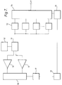
- Fig. 1 is a part schematic plan view of a crystal resonator adapted to oscillate in a pair of oscillatory modes and provided with electrodes;
- Fig. 2 is a cross-sectional view of the resonator of Fig. 1;
- Figs. 3 and 4 illustrate two forms of mode excitation circuits for use with the resonator of Fig. 1;
- Figs. 5 and 6 illustrate the spatial distribution of typical SC vibrational modes;
and - Fig. 7 shows a frequency synthesiser circuit incorporating a crystal resonator and provided with temperature control of the output frequency.
- Referring to Fig. 1 and 2, the resonator comprises a generally
lenticular quartz body 11 provided with metal, e.g. nichrome/gold,electrodes - The
electrodes - Advantageously the vibrations are excited via an electrode structure which allows preferential coupling by different oscillators to different inharmonic modes thereby avoiding the requirement for narrow band frequency selection or trapping in the oscillation maintaining amplifier.
- The electrode arrangement shown in Figs 1 and 2 is suitable for an SC cut crystal. For an AT cut crystal an electrode arrangement similar to that of a monolithic dual crystal filter would be more appropriate.
- The modes are excited by the application of appropriate potentials to the electrodes. In an SC cut crystal, for example, application of an electric field between the
outer electrodes circuit outputs electrodes - Figure 4 shows an alternative circuit for exciting preferentially an (n,2,l) mode or an (n,l,2) mode, the particular mode being determined by the crystal orientation. This circuit applies identical potentials, via
outputs electrodes output 44, toelectrode 14. - The circuits of Figs 3 and 4 may be used simultaneously as each has only an insignificant effect on the other.
- Clearly a wide range of harmonic modes is available, these modes being somewhat analogous to the various vibrational modes of a flat plate. The system of classifying these modes is defined below.
- Each mode is defined by a three digit characteristic of the form (n, a, b) wherein:-
- n
- is the overtone number, i.e. the number of nodes along the direction k of Fig. 1
- a
- is the number of anti-nodes along the direction j of Fig. 1);
and - b
- is the number of anti-nodes in a direction perpendicular to that of the directions j and k, i.e. the direction i of Fig. 1.
- Typically we employ an (n, l, l) overtone together with any one of the (n, 2, l), the (n, l, 2) or the (n, 2, 2) overtones. The value of n is an integer, including unity. Typically we employ third overtone oscillations or vibrations for which n = 3.
- Figs. 5 and 6 illustrate the spatial distribution of the amplitudes of vibrational inharmonic modes for a 4 dioptre crystal element. The curves show the spatial distribution of the inharmonic vibrations relative to the distance from the crystal centre along the i and j directions defined above.
- Fig. 5 illustrates the amplitude or intensity distribution for a set of fundamental or first harmonic vibrations for which n = 1. For comparative purposes Fig. 5 illustrates an arrangement in which not all the modal energies are trapped within a 5mm radius circle. It is preferred to employ an arrangement in which substantially all the modal energy is confined so as to avoid disturbance of the temperature/frequency response of the modes. In said circumstances a steeper crystal contour can be employed to reduce modal spreading.
- Fig. 6 illustrates the amplitude or intensity distribution of a corresponding set of third harmonic (n = 3) vibrations. As can be seen from Fig. 6 the intensity of the third harmonic modes decays rapidly to zero and thus substantially all the energy is trapped within a 5mm radius circle.
- The appropriate value (or values) of n that may be selected for any particular crystal element may be determined according to the crystal construction. For example, if the crystal has a steep contour so that the fundamental vibration is trapped within e.f. a 5mm diameter circle then there is the possibility of coupling between the third harmonic vibration and the flexual modes of the crystal. In such circumstances it would be appropriate to select vibrational modes for which n = 1. On the other hand, if the crystal has a shallow contour with consequent spreading of the fundamental vibrations then it would be more appropriate to select higher order modes e.g. for which n = 3.
- It will thus be appreciated that, for a particular crystal construction, it will be possible to select two inharmonic vibrations of the same appropriate modal order and which are of similar but not identical frequency.
- Referring now to Fig. 7, there is shown a schematic diagram of a frequency synthesiser incorporating a temperature controlled crystal oscillator. It will be appreciated that this circuit is described by way of example only and is not specific to the particular crystal constructions detailed above.
- The synthesiser includes a reference piezo-
electric resonator 51 driven by associatedoscillator circuits 52 and one of whose output is fed tofrequency divider circuits 53 the outputs of which are mixed viamixer 54. Acontrol circuit 55 determines the particular subdivided frequencies to be mixed at any instant in accordance with a stored division algorithm whereby to provide the desired synthesised output frequency. - The output frequency of the synthesiser is provided with temperature compensation in the following manner. Signals corresponding to the two inharmonics are fed to respective first and
second amplifiers mixer circuit 58. The mixer combines the two amplified signals to obtain a beat frequency corresponding to the frequency difference between the two inharmonics. As the frequency difference between the inharmonics is relatively small, this beat frequency is comparatively low. - The output of the mixer is fed via a
low pass filter 59, which removes the high frequency sum of the inharmonics to afrequency meter circuit 60. Nore that one of the original frequencies may be used as the reference for the frequency meter. Thecircuit 60 provides a frequency, and hence temperature, responsive signal to thecontrol circuit 55 which in response to this input adjusts the division algorithm to compensate for the change in oscillator frequency so as to maintain the output synthesised frequency at a constant value. - It will be appreciated that in other applications the frequency difference signal corresponding to temperature may be employed in a feedback signal to maintain the resonator at a constant temperature and thus at a constant frequency. Alternatively, the arrangement may be used as a thermometer.
Claims (9)
- A method of determining the temperature of a piezo-electric resonator, the method including comparing first and second inharmonically related vibrations of the same vibrational type and overtone order and of similar frequency whereby to derive a signal indicative of the oscillator temperature.
- A method as claimed in claim 1, characterised in that said inharmonic oscillations comprise a (n, l, l) overtone together with either an (n, l, 2) overtone, an (n, 2, l) overtone or an (n, 2, 2) overtone as hereinbefore defined.
- A method as claimed in claim 1 or 2, characterised in that the piezoelectric resonator comprises a quartz crystal.
- A method as claimed in claim 3, characterised in that the crystal cut is SC, AT or BT.
- A method as claimed in claim 3 or 4, characterised in that the quartz crystal comprises a lenticular body.
- A method as claimed in any one of claims 1 to 5, characterised in that said inharmonic vibrations are third harmonics for which n is equal to 3.
- A method as claimed in any one of claims 1 to 6, characterised in that the vibrations are excited via an electrode structure adapted to provide preferential coupling by different oscillators to different inharmonic vibrations.
- A temperature compensated piezo-electric resonator, including means for exciting first and second inharmonically related vibrations of a thickness shear mode of the same overtone order and of similar frequency, and means for deriving by comparison of the inharmonic vibrations, a signal characteristic of the temperature of the resonator.
- A frequency synthesiser, including a piezo-electric resonator, means for deriving submultiples of the resonator frequency, means controlled by a synthesis algorithm for combining selected submultiple frequencies to provide an output synthesiser frequency, means for exciting in said resonator first and second inharmonically related vibrations of a thickness shear mode of the same overtone order and of similar frequency, means for deriving, by comparison of the inharmonic vibrations, a signal corresponding to the temperature of the resonator, and means responsive to the temperature signal for adjusting the synthesis algorithm whereby to maintain the synthesised frequency at a constant value.
Applications Claiming Priority (2)
| Application Number | Priority Date | Filing Date | Title |
|---|---|---|---|
| GB909013056A GB9013056D0 (en) | 1990-06-12 | 1990-06-12 | Temperature sensor |
| GB9013056 | 1990-06-12 |
Publications (3)
| Publication Number | Publication Date |
|---|---|
| EP0463735A2 true EP0463735A2 (en) | 1992-01-02 |
| EP0463735A3 EP0463735A3 (en) | 1992-08-12 |
| EP0463735B1 EP0463735B1 (en) | 1999-02-03 |
Family
ID=10677461
Family Applications (1)
| Application Number | Title | Priority Date | Filing Date |
|---|---|---|---|
| EP91304778A Expired - Lifetime EP0463735B1 (en) | 1990-06-12 | 1991-05-28 | Piezo electric resonator temperature sensor |
Country Status (4)
| Country | Link |
|---|---|
| US (1) | US5149197A (en) |
| EP (1) | EP0463735B1 (en) |
| DE (1) | DE69130843T2 (en) |
| GB (2) | GB9013056D0 (en) |
Cited By (1)
| Publication number | Priority date | Publication date | Assignee | Title |
|---|---|---|---|---|
| EP2106028A1 (en) * | 2008-03-26 | 2009-09-30 | Nokia Siemens Networks Oy | Circuit arrangement and method of operation |
Families Citing this family (16)
| Publication number | Priority date | Publication date | Assignee | Title |
|---|---|---|---|---|
| US5214668A (en) * | 1990-09-28 | 1993-05-25 | Nec Corporation | Temperature detector and a temperature compensated oscillator using the temperature detector |
| US5406829A (en) * | 1994-04-19 | 1995-04-18 | Tektronix, Inc. | Temperature control for chemical sensors |
| US5802195A (en) * | 1994-10-11 | 1998-09-01 | The United States Of America As Represented By The Administrator Of The National Aeronautics And Space Administration | High displacement solid state ferroelectric loudspeaker |
| US5686779A (en) * | 1995-03-01 | 1997-11-11 | The United States Of America As Represented By The Secretary Of The Army | High sensitivity temperature sensor and sensor array |
| US6420938B1 (en) | 2000-08-30 | 2002-07-16 | Lawrence Hoff | Software controlled crystal oscillator |
| JP3903842B2 (en) * | 2001-07-03 | 2007-04-11 | 株式会社村田製作所 | Piezoelectric resonator, filter and electronic communication device |
| US6859116B2 (en) * | 2001-07-30 | 2005-02-22 | Kyocera Corporation | Piezoelectric resonator |
| JP4864370B2 (en) * | 2005-07-22 | 2012-02-01 | 日本電波工業株式会社 | Temperature sensor |
| DE102010040039A1 (en) | 2010-08-31 | 2012-03-01 | Endress + Hauser Wetzer Gmbh + Co Kg | Method and device for in situ calibration of a thermometer |
| US20150059483A1 (en) * | 2013-09-03 | 2015-03-05 | Delaware Capital Formation, Inc. | Sensors for measuring at least one of pressure and temperature, and related assemblies and methods |
| DE102015112425A1 (en) | 2015-07-29 | 2017-02-02 | Endress + Hauser Wetzer Gmbh + Co. Kg | Method and device for in situ calibration of a thermometer |
| DE102017100268A1 (en) | 2017-01-09 | 2018-07-12 | Endress + Hauser Wetzer Gmbh + Co. Kg | Apparatus and method for in situ calibration of a thermometer |
| DE102017100266A1 (en) | 2017-01-09 | 2018-07-12 | Endress + Hauser Wetzer Gmbh + Co. Kg | Temperature limit sensors |
| DE102017100264A1 (en) | 2017-01-09 | 2018-07-12 | Endress + Hauser Wetzer Gmbh + Co. Kg | Apparatus and method for in situ calibration of a thermometer |
| DE102018102535B3 (en) | 2018-02-05 | 2019-03-28 | Elmos Semiconductor Aktiengesellschaft | Temperature measurement by means of the impedance of an ultrasonic transducer |
| DE102021113198A1 (en) | 2021-05-20 | 2022-11-24 | Endress + Hauser Wetzer Gmbh + Co. Kg | In situ temperature calibration |
Citations (1)
| Publication number | Priority date | Publication date | Assignee | Title |
|---|---|---|---|---|
| EP0136627A2 (en) * | 1983-10-03 | 1985-04-10 | Quartztronics, Inc. | Resonator transducer system with temperature compensation |
Family Cites Families (10)
| Publication number | Priority date | Publication date | Assignee | Title |
|---|---|---|---|---|
| DE3145245C2 (en) * | 1980-11-18 | 1985-11-14 | Kabushiki Kaisha Suwa Seikosha, Shinjuku, Tokio/Tokyo | Thermometer with a quartz crystal oscillator |
| JPS5885610A (en) * | 1981-11-16 | 1983-05-23 | Murata Mfg Co Ltd | Three-terminal type oscillator |
| CH650122GA3 (en) * | 1981-12-17 | 1985-07-15 | ||
| NL8202649A (en) * | 1982-07-01 | 1984-02-01 | Philips Nv | TEMPERATURE SENSOR. |
| US4481488A (en) * | 1982-11-08 | 1984-11-06 | Motorola, Inc. | Trapped energy resonator for oscillator and multiple resonator applications |
| US4872765A (en) * | 1983-04-20 | 1989-10-10 | The United States Of America As Represented By The Secretary Of The Army | Dual mode quartz thermometric sensing device |
| FR2545669B1 (en) * | 1983-05-03 | 1985-08-09 | France Etat Armement | TEMPERATURE COMPENSATED QUARTZ OSCILLATOR |
| US4625138A (en) * | 1984-10-24 | 1986-11-25 | The United States Of America As Represented By The Secretary Of The Army | Piezoelectric microwave resonator using lateral excitation |
| SU1525488A1 (en) * | 1987-12-16 | 1989-11-30 | Харьковский авиационный институт им.Н.Е.Жуковского | Piezoelectric transducer |
| JP2790180B2 (en) * | 1987-12-29 | 1998-08-27 | 株式会社村田製作所 | Electrostrictive resonance device |
-
1990
- 1990-06-12 GB GB909013056A patent/GB9013056D0/en active Pending
-
1991
- 1991-05-28 DE DE69130843T patent/DE69130843T2/en not_active Expired - Fee Related
- 1991-05-28 EP EP91304778A patent/EP0463735B1/en not_active Expired - Lifetime
- 1991-05-28 US US07/706,216 patent/US5149197A/en not_active Expired - Lifetime
- 1991-06-12 GB GB9112638A patent/GB2246862B/en not_active Expired - Fee Related
Patent Citations (1)
| Publication number | Priority date | Publication date | Assignee | Title |
|---|---|---|---|---|
| EP0136627A2 (en) * | 1983-10-03 | 1985-04-10 | Quartztronics, Inc. | Resonator transducer system with temperature compensation |
Cited By (1)
| Publication number | Priority date | Publication date | Assignee | Title |
|---|---|---|---|---|
| EP2106028A1 (en) * | 2008-03-26 | 2009-09-30 | Nokia Siemens Networks Oy | Circuit arrangement and method of operation |
Also Published As
| Publication number | Publication date |
|---|---|
| US5149197A (en) | 1992-09-22 |
| DE69130843D1 (en) | 1999-03-18 |
| EP0463735A3 (en) | 1992-08-12 |
| GB9013056D0 (en) | 1990-08-01 |
| GB2246862B (en) | 1993-09-29 |
| EP0463735B1 (en) | 1999-02-03 |
| GB2246862A (en) | 1992-02-12 |
| GB9112638D0 (en) | 1991-07-31 |
| DE69130843T2 (en) | 1999-06-10 |
Similar Documents
| Publication | Publication Date | Title |
|---|---|---|
| US5149197A (en) | Piezo electric resonator temperature sensor | |
| US5200714A (en) | Crystal oscillator with quartz vibrator having temperature detecting faculty, quartz vibrator for use therein, and method of measuring temperature using quartz vibrator | |
| US3826931A (en) | Dual crystal resonator apparatus | |
| Parker et al. | Precision surface-acoustic-wave (SAW) oscillators | |
| US3479536A (en) | Piezoelectric force transducer | |
| US4872765A (en) | Dual mode quartz thermometric sensing device | |
| US4144747A (en) | Simultaneously resonated, multi-mode crystal force transducer | |
| JPS60105917A (en) | Resonance conversion system, resonance-force conversion system and method of determining force or other parameter and temperature | |
| JPH0450968B2 (en) | ||
| TW201312939A (en) | Crystal resonator and crystal oscillator | |
| JPS5829645B2 (en) | Onpahatsushinki | |
| EP0054447B1 (en) | Stress-compensated quartz resonators | |
| US4472656A (en) | Temperature sensor and method using a single rotated quartz crystal | |
| US4199990A (en) | Elastic surface wave accelerometer | |
| US5299175A (en) | Electroacoustic unit for generating high sonic and ultra-sonic intensities in gases and interphases | |
| GB1449841A (en) | Oscillators | |
| US3143889A (en) | Angular velocity measuring device | |
| WO1988008209A1 (en) | Force sensing vibrating beam resonator | |
| Shmaliy | The modulational method of quartz crystal oscillator frequency stabilization | |
| Gerber et al. | Quartz frequency standards | |
| JPS58190115A (en) | Piezoelectric oscillator | |
| JPH03252204A (en) | Temperature compensated crystal oscillator | |
| Booker et al. | Dispersion of elastic waves in a triangular bar | |
| JPS60192206A (en) | Vibration type angular velocity meter | |
| RU2455754C1 (en) | Temperature-compensated crystal-controlled oscillator |
Legal Events
| Date | Code | Title | Description |
|---|---|---|---|
| PUAI | Public reference made under article 153(3) epc to a published international application that has entered the european phase |
Free format text: ORIGINAL CODE: 0009012 |
|
| AK | Designated contracting states |
Kind code of ref document: A2 Designated state(s): CH DE FR LI |
|
| PUAL | Search report despatched |
Free format text: ORIGINAL CODE: 0009013 |
|
| AK | Designated contracting states |
Kind code of ref document: A3 Designated state(s): CH DE FR LI |
|
| 17P | Request for examination filed |
Effective date: 19930105 |
|
| 17Q | First examination report despatched |
Effective date: 19950407 |
|
| GRAG | Despatch of communication of intention to grant |
Free format text: ORIGINAL CODE: EPIDOS AGRA |
|
| RAP1 | Party data changed (applicant data changed or rights of an application transferred) |
Owner name: NORTHERN TELECOM LIMITED |
|
| GRAG | Despatch of communication of intention to grant |
Free format text: ORIGINAL CODE: EPIDOS AGRA |
|
| GRAH | Despatch of communication of intention to grant a patent |
Free format text: ORIGINAL CODE: EPIDOS IGRA |
|
| GRAH | Despatch of communication of intention to grant a patent |
Free format text: ORIGINAL CODE: EPIDOS IGRA |
|
| GRAA | (expected) grant |
Free format text: ORIGINAL CODE: 0009210 |
|
| AK | Designated contracting states |
Kind code of ref document: B1 Designated state(s): CH DE FR LI |
|
| REG | Reference to a national code |
Ref country code: CH Ref legal event code: NV Representative=s name: JOHN P. MUNZINGER INGENIEUR-CONSEIL Ref country code: CH Ref legal event code: EP |
|
| REF | Corresponds to: |
Ref document number: 69130843 Country of ref document: DE Date of ref document: 19990318 |
|
| ET | Fr: translation filed | ||
| RAP4 | Party data changed (patent owner data changed or rights of a patent transferred) |
Owner name: NORTEL NETWORKS CORPORATION |
|
| PLBE | No opposition filed within time limit |
Free format text: ORIGINAL CODE: 0009261 |
|
| STAA | Information on the status of an ep patent application or granted ep patent |
Free format text: STATUS: NO OPPOSITION FILED WITHIN TIME LIMIT |
|
| 26N | No opposition filed | ||
| REG | Reference to a national code |
Ref country code: CH Ref legal event code: PFA Free format text: NORTEL NETWORKS CORPORATION TRANSFER- NORTEL NETWORKS LIMITED * NORTHERN TELECOM LIMITED TRANSFER- NORTEL NETWORKS CORPORATION Ref country code: CH Ref legal event code: NV Representative=s name: CRONIN INTELLECTUAL PROPERTY |
|
| PGFP | Annual fee paid to national office [announced via postgrant information from national office to epo] |
Ref country code: FR Payment date: 20030422 Year of fee payment: 13 |
|
| PGFP | Annual fee paid to national office [announced via postgrant information from national office to epo] |
Ref country code: CH Payment date: 20030516 Year of fee payment: 13 |
|
| PGFP | Annual fee paid to national office [announced via postgrant information from national office to epo] |
Ref country code: DE Payment date: 20030530 Year of fee payment: 13 |
|
| REG | Reference to a national code |
Ref country code: FR Ref legal event code: CD |
|
| PG25 | Lapsed in a contracting state [announced via postgrant information from national office to epo] |
Ref country code: LI Free format text: LAPSE BECAUSE OF NON-PAYMENT OF DUE FEES Effective date: 20040531 Ref country code: CH Free format text: LAPSE BECAUSE OF NON-PAYMENT OF DUE FEES Effective date: 20040531 |
|
| PG25 | Lapsed in a contracting state [announced via postgrant information from national office to epo] |
Ref country code: DE Free format text: LAPSE BECAUSE OF NON-PAYMENT OF DUE FEES Effective date: 20041201 |
|
| REG | Reference to a national code |
Ref country code: CH Ref legal event code: PL |
|
| PG25 | Lapsed in a contracting state [announced via postgrant information from national office to epo] |
Ref country code: FR Free format text: LAPSE BECAUSE OF NON-PAYMENT OF DUE FEES Effective date: 20050131 |
|
| REG | Reference to a national code |
Ref country code: FR Ref legal event code: ST |