EP0463066B1 - Electrical discharge machine apparatus tilted current pickup - Google Patents
Electrical discharge machine apparatus tilted current pickup Download PDFInfo
- Publication number
- EP0463066B1 EP0463066B1 EP90905144A EP90905144A EP0463066B1 EP 0463066 B1 EP0463066 B1 EP 0463066B1 EP 90905144 A EP90905144 A EP 90905144A EP 90905144 A EP90905144 A EP 90905144A EP 0463066 B1 EP0463066 B1 EP 0463066B1
- Authority
- EP
- European Patent Office
- Prior art keywords
- bore
- longitudinal axis
- wire
- axis
- straight line
- Prior art date
- Legal status (The legal status is an assumption and is not a legal conclusion. Google has not performed a legal analysis and makes no representation as to the accuracy of the status listed.)
- Expired - Lifetime
Links
- 238000006073 displacement reaction Methods 0.000 claims abstract description 16
- 230000013011 mating Effects 0.000 claims description 10
- 230000008878 coupling Effects 0.000 claims description 7
- 238000010168 coupling process Methods 0.000 claims description 7
- 238000005859 coupling reaction Methods 0.000 claims description 7
- 229910003460 diamond Inorganic materials 0.000 claims description 2
- 239000010432 diamond Substances 0.000 claims description 2
- 239000012530 fluid Substances 0.000 description 30
- 230000000712 assembly Effects 0.000 description 20
- 238000000429 assembly Methods 0.000 description 20
- 238000011010 flushing procedure Methods 0.000 description 10
- 238000005520 cutting process Methods 0.000 description 7
- 239000000463 material Substances 0.000 description 7
- 239000004020 conductor Substances 0.000 description 4
- 238000007493 shaping process Methods 0.000 description 4
- 230000003247 decreasing effect Effects 0.000 description 3
- 230000006835 compression Effects 0.000 description 2
- 238000007906 compression Methods 0.000 description 2
- 230000000717 retained effect Effects 0.000 description 2
- 229910001220 stainless steel Inorganic materials 0.000 description 2
- 239000010935 stainless steel Substances 0.000 description 2
- 229910052582 BN Inorganic materials 0.000 description 1
- PZNSFCLAULLKQX-UHFFFAOYSA-N Boron nitride Chemical compound N#B PZNSFCLAULLKQX-UHFFFAOYSA-N 0.000 description 1
- 238000005299 abrasion Methods 0.000 description 1
- 239000013078 crystal Substances 0.000 description 1
- 239000008367 deionised water Substances 0.000 description 1
- 229910021641 deionized water Inorganic materials 0.000 description 1
- 238000010586 diagram Methods 0.000 description 1
- 230000005611 electricity Effects 0.000 description 1
- 239000007789 gas Substances 0.000 description 1
- 230000014759 maintenance of location Effects 0.000 description 1
- 229910052751 metal Inorganic materials 0.000 description 1
- 239000002184 metal Substances 0.000 description 1
- 229910052594 sapphire Inorganic materials 0.000 description 1
- 239000010980 sapphire Substances 0.000 description 1
- 230000007704 transition Effects 0.000 description 1
- WFKWXMTUELFFGS-UHFFFAOYSA-N tungsten Chemical compound [W] WFKWXMTUELFFGS-UHFFFAOYSA-N 0.000 description 1
- 229910052721 tungsten Inorganic materials 0.000 description 1
- 239000010937 tungsten Substances 0.000 description 1
- UONOETXJSWQNOL-UHFFFAOYSA-N tungsten carbide Chemical compound [W+]#[C-] UONOETXJSWQNOL-UHFFFAOYSA-N 0.000 description 1
- XLYOFNOQVPJJNP-UHFFFAOYSA-N water Chemical compound O XLYOFNOQVPJJNP-UHFFFAOYSA-N 0.000 description 1
Images



Classifications
-
- B—PERFORMING OPERATIONS; TRANSPORTING
- B23—MACHINE TOOLS; METAL-WORKING NOT OTHERWISE PROVIDED FOR
- B23H—WORKING OF METAL BY THE ACTION OF A HIGH CONCENTRATION OF ELECTRIC CURRENT ON A WORKPIECE USING AN ELECTRODE WHICH TAKES THE PLACE OF A TOOL; SUCH WORKING COMBINED WITH OTHER FORMS OF WORKING OF METAL
- B23H7/00—Processes or apparatus applicable to both electrical discharge machining and electrochemical machining
- B23H7/02—Wire-cutting
- B23H7/08—Wire electrodes
- B23H7/10—Supporting, winding or electrical connection of wire-electrode
-
- B—PERFORMING OPERATIONS; TRANSPORTING
- B23—MACHINE TOOLS; METAL-WORKING NOT OTHERWISE PROVIDED FOR
- B23H—WORKING OF METAL BY THE ACTION OF A HIGH CONCENTRATION OF ELECTRIC CURRENT ON A WORKPIECE USING AN ELECTRODE WHICH TAKES THE PLACE OF A TOOL; SUCH WORKING COMBINED WITH OTHER FORMS OF WORKING OF METAL
- B23H7/00—Processes or apparatus applicable to both electrical discharge machining and electrochemical machining
- B23H7/02—Wire-cutting
- B23H7/08—Wire electrodes
- B23H7/10—Supporting, winding or electrical connection of wire-electrode
- B23H7/107—Current pickups
Definitions
- the present invention relates to an electrical discharge machine (EDM) according to the preamble of claim 1.
- EDM electrical discharge machine
- EDM apparatuses utilizing a moving wire electrode are commonly presently used in making precise cuts and shaping various electrically conductive materials or workpieces.
- the wire electrode is wound around and travels between two turning spools and a pair of wire guides or guide assemblies wherethrough the wire travels are used to accurately situate or guide the moving wire electrode at the proper location and/or at angle with respect to the workpiece being cut.
- the wire and workpiece are placed at different electrical potentials and a controlled electrical spark traveling between the wire and workpiece causes the workpiece to be eroded and cut or shaped in a desired configuration.
- the present current pickups with a bore can be indexed or rotated, a groove often time forms in the bore wall and the current pickup must be rotated sufficiently so as to prevent the wire electrode from slipping back into that groove, thereby also wasting potential contact surface area therebetween.
- JP-A-60-249531 describes that the known tilting of the longitudinal axis of a bore for guiding and contacting a wire in its' normal straight line of travel results in a high degree of abrasion.
- the publication describes means to avoid tilting of the longitudinal axis of the bore by combining the bottom part of an electricity feeding die holder with the top part of a guide body to set and keep these in a straight line.
- the EP-A2-0161657 discloses the tilting of wire guide elements with respect to a workpiece but nothing about supporting and pivoting a current pickup where through electrical current could be placed on the wire.
- the object of the present invention is achieved through the electrical discharge machine according to claim 1.
- the present invention overcomes the disadvantages associated with prior current pickup assemblies by providing a current pickup or body having a bore therethrough and defining a bore longitudinal axis.
- the bore longitudinal axis is placed at an angle with respect to the normal straight line of wire travel and intersecting the normal straight line of travel substantially at a longitudinal midpoint of the bore. Accordingly, the wire electrode contacts the contact wall on one side at one end of the midpoint and contacts the contact wall on the other side at the other end of the midpoint, cancelling any deformation or curl on the wire electrode and increasing cutting accuracy.
- the tension in the wire electrode can be increased, thereby also providing better electrical rubbing or sliding contact and still substantially preventing curl in the wire.
- the bore is also curvilinear and cylindrically shaped, increasing in diameter outwardly from the midpoint, thus, further providing a smooth sliding contact between the wire electrode and the bore contact wall, preventing deformation in the wire and increasing accuracy.
- a pivot means is provided whereby the current pickup is selectively pivoted at a given angle with respect to the normal straight line of wire travel thereby selectively increasing or decreasing the tension in the wire electrode and, also, selectively aligning the bore longitudinal axis with the normal straight line of wire travel and, facilitating and making manual and automatic threading substantially easier.
- the current pickup is also rotated about the bore longitudinal axis, either manually or automatically, and incrementally or linearly, thereby using substantially all of the bore contact wall and substantially increasing the useful life of the current pickup or conductive body. Furthermore, as the bore contact wall wears, the angle between the bore longitudinal axis and the normal straight line of wire travel can be increased, thereby retaining the necessary tension in the wire, even though the bore contact wall has worn.
- the present invention further provides a gimball means whereby the current pickup or conductive body is supported and selectively gimballed about a point along the wire electrode normal straight line of travel whereby the bore longitudinal axis is selectively pivoted about two mutually perpendicular and intersecting axes of rotation intersecting at the point.
- a control shaft is connected to the current pickup and rotational and cantilever movement of the control shaft causes pivotal movement of the conductive body about the respective intersecting axes of rotation.
- a connecting rod is cammed between two cam walls, is engaged with the control shaft at its first end, and is pivotally connected to a drive means at its second end so that rotational movement of the connecting rod second end causes simultaneous rotational and cantilever movement of the control shaft and, also, simultaneous rotation of the bore longitudinal axis about the wire electrode normal straight line of travel.
- a variable radial displacement means is provided between the drive means and the connecting rod and selectively radially displaces the connecting rod second end pivotal connection from the drive means axis so that, when the pivotal connection is coaxial with the drive means axis, the conductive body bore longitudinal axis and the wire electrode normal straight line of travel are co-linear, thus facilitating manual and automatic threading. Further, by increasing the radial displacement between the drive means axis and the pivotal connection between the connecting rod second end, the angle between the bore longitudinal axis and the normal straight line of wire travel is selectively increased. Accordingly, the tension in the wire electrode is selectively controlled while the current pickup bore contact wall is worn and the useful life of the current pickup is increased by utilizing substantially all of the current pickup bore contact wall.
- the present invention provides for various gimballing means including: a ring member pivotally supported in a support assembly about one of two perpendicular and intersecting axes and wherein the current pickup is pivotally supported in the ring member on a control shaft about the other of the perpendicular and intersecting axes; a spring-type assembly wherein a first annular member is supported in a support assembly, two leaf springs extend longitudinally therefrom, a second annular member is connected to the first leaf springs at their other ends, second leaf springs connected to the second annular member and extending longitudinally therefrom and, wherein the conductive body or current pickup is connected to the second leaf springs at their second ends; and, a ball having a center point journalled in a socket and wherein the conductive body is attached to the ball with the bore longitudinal axis intersecting the ball center point.
- the wire electrode is guided between a pre guide member and a post guide member in the normal straight line of wire travel and the distance between each guide member and the midpoint of the bore longitudinal axis is equal thereby also providing an equal amount of tension in the wire on both sides of the midpoint and, thus, maximizing electrical rubbing contact while substantially preventing curl in the wire electrode. Further, by rotating or gimballing the current pickup, the useful life is substantially increased and, thus, problems associated with replacing a current pickup that has worn during a cutting process and creating inaccuracies thereby are substantially decreased.
- the present invention is directed to a current pickup assembly for placing electrical current on an electrical discharge machine apparatus moving wire electrode having a normal straight line of travel.
- the current pickup assembly includes a conductive body having a bore for receiving the wire electrode therethrough and, a wire contact wall.
- the bore longitudinal axis is at an angle with respect to the normal straight line of wire travel and the moving wire electrode contacts the contact wall.
- the present invention is directed to a current pickup assembly for placing electrical current on an electrical discharge machine apparatus moving wire electrode having a normal straight line of travel.
- the current pickup assembly includes a conductive body having a bore with a conductive wall for receiving the wire electrode therethrough and, defining a longitudinal axis.
- a pivot means is provided for supporting the body and selectively pivoting the bore longitudinal axis at an angle with respect to the normal straight line of wire travel so that the moving wire electrode selectively contacts the contact wall.
- the present invention is directed to a current pickup assembly for placing electric current on an electrical discharge machine apparatus moving wire electrode having a normal straight line of travel.
- the current pickup assembly includes a conductive body having a bore with a contact wall for receiving the wire electrode therethrough and, defining a longitudinal axis.
- a gimball means is provided for supporting the body and selectively gimballing and pivoting the bore longitudinal axis at a point defined by two mutually perpendicular and intersecting axes of rotation intersecting at the point so that the moving wire electrode may contact the contact wall.
- the specific embodiments relate to current pickup assemblies for placing electric current on an electrical discharge machine apparatus moving wire electrode, as well as guide assemblies for guiding an electrical discharge machine apparatus moving wire electrode.
- an electrical discharge machine utilizes a wire electrode 12 wrapped around spools 14. Spools 14 are rotated and wire electrode 12 travels therebetween. Wire guide assemblies generally indicated as 16, are mounted on the ends of arms 18. Wire electrode 12 is received through assemblies 16 and is guided thereby. Workpiece 20, generally made of a conductive material, is held on table 22 so that it may be cut and/or shaped by the moving wire electrode 12. More specifically, arms 18 and/or table 22 are moved with respect to one another so that wire electrode 12 may travel through workpiece 20 cutting and shaping the same in a predetermined desired manner. Arms 18 may be displaced with respect to one another and also thereby cutting workpiece 20 at a given desired angle.
- the cutting and shaping of workpiece 20 is caused by the moving wire electrode 12 as it travels between spools 14 by the placement of a different electrical potential on wire 12 and workpiece 20, thereby causing a spark therebetween and electroeroding workpiece 20 in the proximity of the traveling wire electrode 12.
- Figs. 2 and 3 The working features of the current pickup assemblies are diagrammatically shown in Figs. 2 and 3 whereat the X, Y, and Z axes are utilized depicting a three dimensional or perspective diagram.
- the Z axis defines the normal straight line of travel for moving wire electrode 12 between pre guide member 24 and post guide member 26.
- Pre guide member 24 includes a bore or hole 28 therethrough and post guide member 26 also includes a bore or hole 30 therethrough. Bores 28 and 30 are adapted for receiving therethrough wire electrode 12 and guiding the same along the Z axis or the normal straight line of travel.
- Pre guide member 24 is affixed and supported on pre guide support 32 and post guide member 26 is affixed and supported on post guide support 34.
- a conductive body is depicted in dashed lines and as having a generally cylindrical shape 36.
- Conductive body 36 is preferably made of tungsten or tungsten carbide.
- Conductive body 36 includes a bore 38 longitudinally through conductive body 36 and having a longitudinal axis R.
- Conductive body bore 38 is also depicted in dashed lines and is also depicted as being curvilinear in cross section and cylindrically shaped, increasing in diameter outwardly from the longitudinal midpoint, here shown as the intersection between the X and Y axes.
- a contact wall 40 is provided in conductive body 36 here depicted as the wall of conductive body bore 38.
- Conductive body 36 is electrically connected to a power source (not shown) and transfers or places electrical current on wire electrode 12 as wire electrode 12 rubs or slides against and contacts contact wall 40.
- conductive body bore longitudinal axis R is situated at an angle alpha ( ⁇ ) with respect to the Z axis or the normal straight line of wire travel.
- angle ⁇ is fixed and wire electrode 12 travels through bore 38 and, under normal tension, wire electrode 12 contacts contact wall 40 on one side at one end of midpoint 42 and contacts contact wall 40 on the other side at the other end of midpoint 42. Therefore, deformation or curl of wire electrode 12 is substantially minimized and, thus, cutting accuracy is increased.
- guide members 24 and 26 are situated at an equal distance D away from midpoint 42.
- a means for rotating conductive body 36 about bore longitudinal axis R as indicated by arrows 44 there is provided a means for rotating conductive body 36 about bore longitudinal axis R as indicated by arrows 44.
- the means for rotating can be manual or automated. Further, the rotation of conductive body 38 can be linear, thus, causing substantially even wear on contact wall 40 or, in the alternative, can be incremental.
- a pivot means is provided for supporting conductive body 36 and selectively pivoting the conductive body bore axis R at any desired angle ⁇ with respect to the normal straight line of wire travel or the Z axis.
- conductive body bore longitudinal axis R can selectively be situated collinear with the Z axis, thus, making manual and/or automatic threading of wire electrode 12 substantially easier.
- the tension on wire electrode 12 can also be selectively increased or decreased, thus, also providing selective control of the electrical transfer between contact wall 40 and wire electrode 12 and selective control of the wear of contact wall 40.
- a means for rotating conductive body 36 may also be provided with the second embodiment, thus, substantially fully utilizing contact wall 40 and increasing the useful life thereof.
- Various means for pivoting and rotating are described hereinbelow.
- a gimball means is provided for supporting conductive body 36 and selectively gimballing the bore longitudinal axis R about midpoint 42.
- bore longitudinal axis R may be pivoted about mutually perpendicular and intersecting axes X and Y at a given angle ⁇ in an infinite number of planes parallel with the Z axis.
- a control shaft 46 is connected to conductive body 36. By rotating control shaft 46, as indicated by arrows 48 and pivoting or causing cantilever movement of control shaft 46, as indicated by arrows 50, conductive body bore longitudinal axis R can selectively be placed at any given angle ⁇ and in any plane that is parallel with the Z axis.
- control shaft 46 by preprogrammed control of the rotational and cantilever movement of control shaft 46 as described hereinbelow, bore longitudinal axis R can be caused to pivot about the X and Y axes so as to rotate about the Z axis as indicated by the dashed ring lines of travel 52 at any given angle ⁇ . Accordingly, all the advantages discussed hereinabove with respect to the first and second current pickup assembly embodiments are attained also by this third embodiment.
- the preprogrammed control of control shaft 46 is achieved with a connecting rod member 54.
- Connecting rod 54 includes a first end 56 engaging control shaft 46 and a second end 58 pivotally connected to a drive means at pivotal point connection 64.
- Connecting rod member 54 further includes front face 66 and back face 68. At the first end 56 of connecting rod 54, a generally square aperture or window 70 is provided through connecting rod member 54 with openings in faces 66 and 68. As shown, control shaft 46 is generally square and is received in square aperture 70. Between faces 66 and 68, there are also provided connecting rod cam surfaces 72 slidingly engaging cam walls 74, shown in Fig. 3 in dashed lines.
- control shaft 46 Upon rotational movement of second end 58 of connecting rod 54 about pivot point 64 via the drive means, about the drive means axis 60 as indicated by arrows 76, through the engagement of control shaft 46 with connecting rod 54 in aperture 70, control shaft 46 is both rotated as indicated by arrows 48 and moved upward and downward in a cantilever fashion as indicated by arrows 50. Depending on the radial distance between drive means axis 60 and pivot point connection 64, control shaft 46 is pivoted as indicated by arrows 48 at an angle beta ⁇ .
- conductive body longitudinal bore R is rotated about the Z axis or the wire electrode normal straight line of travel as indicated by dashed ring lines of travel 52.
- angle ⁇ is proportional to angle ⁇ and by selectively radially displacing pivot point connection 64 from drive means axis 60, angle ⁇ and the radial displacement of longitudinal bore axis R as indicated by dashed lines 52 can be selectively controlled.
- a plunger generally indicated as 78 is received in sleeve or cylindrical opening 80.
- Plunger 78 has an exterior cylindrical surface 82 and is adapted for reciprocal and rotational movement in sleeve 80.
- Plunger 78 includes a first end 84 and a second end 86.
- Plunger 78 is rotatably driven at its second end 86 thereof by a drive means or motor M through a longitudinally expandable coupling generally indicated as 88.
- Coupling 88 includes a square shaft 90 connected to plunger 78 at its second end 86 and a coupling member 92 connected to motor M via motor shaft 94 and rotatably driven by motor M as indicated by arrows 96.
- Coupling member 92 includes a longitudinal square hollow coaxially aligned with drive means axis 60 and adapted to reciprocally receive square shaft 90 therein.
- plunger 78 can be reciprocally moved along drive means axis 60 within sleeve 80 as indicated by arrows 100 while rotatably driven via longitudinally expandable coupling 88 and motor M.
- plunger 78 The reciprocal movement of plunger 78 can be controlled manually or automatically and a typical manual plunger reciprocal movement control is shown in Figs. 4 and 7. More specifically, plunger 78 includes annular rings 102 near the second end 86 and defining an annular groove 104 therebetween.
- An adjustment screw 106 is journalled in bores 108 and 110 of support structure 112. Adjustment screw 106 includes a control knob 114 and a threaded portion 116 threadingly engaging ear 118.
- Ear 118 includes a threaded bore 120 for threadingly receiving threaded portion 116 of adjustment screw 106 and, further, includes a tongue portion 122 received within annular groove 104.
- Tongue portion 122 slidingly engages annular rings 102 as plunger 78 is rotated about drive means axis 60, thus, by selectively rotating adjustable screw 106 as indicated by arrows 124, ear 118 is selectively reciprocated thereby also causing plunger 78 to be selectively reciprocally moved along drive means axis 60.
- plunger 78 can be housed in a pneumatic cylinder and air pressure supplied selectively within the pneumatic cylinder in chambers formed on the ends 84 and 86 of plunger 78 thereby selectively reciprocating plunger 78 therein.
- a stop can be incorporated for selectively placing plunger 78 at a desired longitudinal position within the pneumatic cylinder at the end of the particular stroke thereof and, thus, controlling the radial displacement between drive means axis 60 and pivot point connection 64.
- a drive shaft 126 having a first end indicated as 128 and a second end indicated as 130.
- a drive shaft bore 132 is provided in plunger 78 extending therein from face 134 of plunger 78.
- Drive shaft bore 132 is substantially square shaped with a longitudinal drive shaft bore axis 136 situated at an angle with respect to drive means axis 60 and intersecting therewith at a point 138.
- Drive shaft 126 is also substantially square shaped and is adapted to be slidingly received in drive shaft bore 132.
- drive shaft 126 is pivotally connected to connecting rod 54 about pivot point 64.
- This pivotal connection is adapted to prevent longitudinal movement thereat of drive shaft 126 via retention rings 140 and/or by other suitable means.
- Cylindrical shaft 142 is journalled in cylindrical hole 144 for pivotal movement therebetween as described hereinabove. Accordingly, reciprocal longitudinal movement of plunger 78 causes reciprocal sliding of drive shaft 126 within drive shaft bore 132 and, thereby, providing selective radial displacement of pivotal point connection 64 from drive means axis 60. More specifically, movement of plunger 78 away from connecting rod 54 causes the greatest radial displacement while movement of plunger 78 towards connecting rod 54 coaxially aligns pivotal point connection 64 with drive means axis 60.
- wire guide assemblies 16 include a first guide member or means 148 also referred to as the final guide and having a bore 150 therethrough, a second guide member or means 152 also referred to as the post guide and having a bore 154 therethrough and, a third guide member or means 156 also referred to as the pre guide and having a bore 158 therethrough. Bores 150, 154, and 158 receive the moving wire electrode 12 therethrough and guide the wire in the normal straight line of wire travel.
- the various current pickup assemblies are located between second guide or post guide member 152 and third guide or pre guide member 156 and first guide or final guide member 148 is located on the working end of guide assembly 16 or closest to workpiece 18.
- Post guide 26 includes a post guide holder body 160 having a wire passageway 162 therethrough between a first opening 164 and a second opening 166.
- Post guide holder body 160 includes an enlarged portion generally indicated as 168 and a thinner portion generally indicated as 170.
- Enlarged portion 168 includes outer frusto-conically shaped walls 172 and fluid channels 176 extending generally longitudinally thereon.
- a guide support is provided on barrel 146 and, more specifically, at one end of barrel 146.
- a frusto-conical inner surface 176 is formed converging toward a hole or opening 178.
- Enlarged portion 168 of post guide holder body 160 is larger than guide support hole 178 and walls 172 thereof seat against frusto-conical inner surface 176 and, thus, also form fluid channels 174 therebetween.
- thinner portion 170 of post guide holder body 160 is smaller than guide support hole 178 and is, thus, received therethrough as shown.
- Threads 180 are provided on thinner portion 170 and a guide nut means or member 182 includes threads 184 adapted for mating engagement with the thinner portion threads 180.
- nut member annular flat 186 is forced against annular flat 188, compressing O-ring member 190 and, in a clamping fashion, locking guide holder body 160 and nut member 182 upon frusto-conical end 192 of barrel 146.
- guide body 16 includes a first counter bore 194 communicating with passageway 162 through first opening 164 and, also, includes a second counter bore 196 communicating with passageway 162 through second opening 166.
- Guide members 148 and 152 are mounted or fixed within respective counterbores 194 and 196 in a mounting material 198.
- Mounting material 198 substantially surrounds the guide members and conical passageways 200 are formed therein converging towards bores 150 and 154 of respective guide members 148 and 152.
- guide members 148 and 152 are made of diamond, polycrystalline or single-crystal, sapphire, cubic boron nitride or other sufficiently wear-resistant materials and, mounting material 198 is made of sintered metal.
- Guide holder body 160 is preferably made of stainless steel.
- Second guide member 152 in the alternative, can be fixed or mounted to guide holder body 160 via a plug 202 as shown in Figs. 6 and 7.
- Plug 202 includes an exterior threaded surface 204 threadingly received in threaded cylindrical bore 206.
- Plug 202 includes a wire passageway having a counterbore or bore portion 208 wherein second guide member 152 is mounted in a mounting material 198 as described hereinabove with respect to Fig. 14.
- Plug 202 further includes tool holes 210 for receiving a mating tool and rotating plug 202 for threadingly engaging threads 206.
- Plug 202 is preferably made of stainless steel.
- Guide nut member 182 in addition to locking guide holder body 160 to the end of barrel 146, aids in the automatic threading of a wire electrode 12 through guide assembly 16 and/or aids in the flushing of workpiece 18.
- guide nut member 182 includes a housing 212 defining a fluid passageway 214 substantially surrounding guide body thinner portion 170.
- a plurality of inlet ports 216 are provided through housing 212 and communicating with fluid passageway 214 and, also, an outlet port 218 is provided and communicates with fluid passageway 214.
- a plurality of threading fluid ports 220 are provided in barrel 146 and communicating with an annular fluid passageway 222 formed between sleeve member 224 and the interior surface 226 of barrel 146.
- Annular fluid passageway 222 includes a curvilinear wall 228 for providing a smooth transition of fluid from threading fluid ports 220 to channels 174.
- a fluid such as deionized water under pressure, is forced as indicated by arrows A through threading fluid ports 220 around annular fluid passageway 222 into channels 174 and aligned inlet port 216 of nut member 182 into fluid passageway 214 and out through outlet port 218.
- outlet port 218 receives therethrough both wire electrode 12 and a threading or flushing fluid.
- threads 184 and inlet ports 216 are formed in cross member 230.
- Cross member 230 is frictionally forced or press fit in bore 232 or affixed therein by any other suitable means.
- fluid received in channels 174, as shown in Fig. 15, travels through inlet ports 216 into fluid passageway 214 and out through outlet bore 218.
- ports 220, channels 174, inlet ports 216, fluid passageway 214, and outlet port 218, are sized so as to continually and gradually decrease in fluid flow area.
- fluid passageway 214 is provided with fluid vanes 234 and defining radial fluid passageways 236 wherethrough the threading fluid flows from fluid passageway 214 and out through outlet port 218.
- Vanes 234 may include a land 238 whereupon guide body thinner portion 170 may rest.
- outlet port 218 may include an enlarged frusto-conical portion 240 whereby during automatic threading, a wire electrode 12 being received through outlet 218, as indicated by arrow B, is aided in finding its way into the bore 150 of first guide member 148.
- flushing nozzle 242 having a threaded interior bore 244 for mating engagement with threads 246 of barrel 146.
- Flushing nozzle 242 includes a flushing fluid inlet 248, a conical passageway 250 surrounding post guide member 26 and a flushing outlet port 252. Flushing fluid is thus received in nozzle 242 through inlet 248 into conical passageway 250 and out through flushing outlet port 252 and onto workpiece 18 thereby flushing the same.
- Barrel 146, at the other end of frusto-conical end 192 includes a threaded interior surface portion 254.
- a cylindrical member 256 having exterior surface threads 258 is threadingly received in barrel 146 and engaging threads 254.
- Cylindrical member 256 includes an annular lip 260 adapted to rest on annular seat 262 thereby positively longitudinally placing third guide member 156.
- a wire passageway including threaded bore 264 is provided in cylindrical member 256 and a plug 270 is threadingly received therein.
- Plug 270 is identical to plug 202 except that third guide member 156, made of the same materials as members 148 and 152, is mounted therein.
- a frusto-conical portion 272 is formed in cylindrical member 256 and leads to conical passageway 200 formed in mounting material 198.
- Tool holes 274 are also provided in cylindrical member 256 for twisting and threadingly engaging cylindrical member 256 within barrel 146.
- outlet bores 276 shown in Fig. 6 extend longitudinally through cylindrical member 256 and allow gases and/or fluid to exit from within barrel 146.
- the various current pickup assemblies are situated within barrel 146 between second guide member 152 and third guide member 156 and with a control shaft 46 extending through a longitudinal bore 278 on the wall of barrel 146.
- barrel 146 can be retained or fixed on an arm 18 by clamping barrel 146 between arm 18 and support structure 112.
- Support structure 112 is affixed to arm 18 via threaded screws 278 received through holes 280 in support structure 112 and threadingly engaged in threaded holes 282 in arm 18.
- cam walls 74 are formed in support structure 112 and connecting rod 54 engaging control shaft 46 is cammed thereagainst.
- the above-discussed radial displacement means and drive means are diagrammatically indicated as 284.
- control shaft 46 For aiding the smooth movement of control shaft 46 as indicated by arrows 48 and 50, the square walls of control shaft 46 received within square aperture 70 of connecting rod 54 are rounded as indicated at 286. Further, a threaded screw 288 is received through a longitudinal bore 290 and used to secure control shaft 46 to conductive body 36 and/or the various current pickup assemblies.
- a first gimball means is shown in Fig. 7 wherein a ball or sphere 292 is journalled in a socket means and conductive body 36 is fixed in a bore 294 extending through ball 292.
- the socket means includes a first annular curvilinear surface 296 formed in sleeve member 224. Within sleeve member 224 there is also received ring member 298 wherein there is formed second annular curvilinear surface 300.
- a second ring member 302 threaded on its exterior surface 304 threadingly engages interior threaded surface 306 of sleeve 224.
- a compression spring 308 having an outer diameter smaller than the inside diameter of sleeve 224 is received between first ring member 298 and second ring member 302 and serves to push ring member 298 against ball 292, thus, journalling ball 292 between surfaces 296 and 300. It is contemplated that other socket assemblies can be used. For example, rather than using a sleeve 224 two ring members having annular curvilinear surfaces can be used for journalling ball 292 and a compression spring situated between cylindrical member 256 and one of the ring members.
- Ball 292 further includes a threaded bore 310 for threadingly receiving screw 288 and attaching control shaft 46 thereon.
- current pickup body 36 is pivoted about the X and Y axes as described hereinabove.
- an electrical power supply is connected to barrel 146 (not shown) and because barrel 146, sleeve 224, ball 292 and conductive body 36 are made of conductive materials, current is transferred and placed on wire electrode 12 as it contacts contact wall 40.
- a conductive body holder 312 is provided for receiving therein a conductive body 36 and retained therein with a cap 314.
- Cap 314 has threads 316 threadingly engaging threads 318 within conductive body holder 312.
- Cap 314 includes an opening 320 and the other end of conductive body holder 312 also has an opening (not shown) and, thus, wire electrode 12 travels through cap 314, conductive body 36 and conductive body holder 312.
- Conductive body 312 is connected to control shaft 46 at 322 and is connected to stud 324 at 326.
- Control shaft 46 and stud 324 are pivotally connected or journalled at 328 and 330 respectively to ring member 332.
- rotational movement of control shaft 46 causes pivotal movement of conductive body holder 312 about the Y axis.
- shaft members 334 which are connected to ring member 332.
- Shaft members 334 are pivotally connected at 336 in a support assembly generally indicated as 338 and which can be in barrel 146. Accordingly, cantilever movement of control shaft 46 as indicated by arrows 50 causes pivotal movement of conductive body holder 312 about the X axis as indicated by arrows 340.
- Shaft members 334, control shaft 46, stud 324 and conductive body holder 312 are made of conductive materials and electrical current can, thus, be transferred to conductive body 36 by applying current to shaft members 334 through support assembly 338.
- a braided wire or the like can be attached to conductive body holder 312 and connected to the power source.
- conductive body 36 can itself be pivotally connected to ring member 332 without utilizing conductive body holder 312.
- a first annular member 342 is supported in a support assembly such as within barrel 146.
- First annular member 342 includes a notch 344 and an inner bore 346.
- a first spring means such as leaf springs 347 are connected at their first end 348 at 350 to first annular member 342.
- Connections 350 can be a longitudinal slot cut into first annular member 342 and receiving first end 348 of leaf spring 347.
- Leaf springs 347 extend longitudinally from first annular member 342 and are adapted for cantilever movement at their second end 352 with respect to the first annular member in a first plane or generally about a line formed between connections 350 of leaf springs 347 to first annular member 342.
- a second annular member 354 is generally oval-shaped and has an inner cavity 356. Second annular member 354 is connected to leaf springs 347 at their second ends 352 thereof at the longitudinal ends 358 of second annular member 354. Second annular member 354 also includes a notch 360 located longitudinally above notch 344.
- Second spring means or two other leaf springs 362 are connected to the second annular member 354 at 364.
- Connections 364 of leaf springs 362 are identical to connections 350 and leaf springs 362 extend longitudinally therefrom towards first annular member 342 and, because second annular member 354 is oval-shaped and connections 364 are at the shortest radial distance from the Z axis, leaf springs 362 extend to within inner bore 346 of first annular member 342. Accordingly, the second ends 366 are adapted for cantilever movement about a line defined between connections 364 in a second plane perpendicular to the first plane.
- a third annular member 368 is connected to leaf springs 362 at connections 370 in a similar fashion as connections 350.
- Third annular member 368 includes a conductive body receiving bore 372 adapted to receive therein conductive body or pickup 36.
- An L-shaped arm 374 is connected to third annular member 368 and includes a threaded hole 376 through L-shaped arm 374 and third annular member 368.
- a small screw 378 is received in and through threaded hole 376 and when conductive body 36 is situated within third annular member 368 as shown in Fig. 9, serves to lock or clamp conductive body 36 within third annular member 368.
- At the other end of L-shaped arm 374 there is a threaded hole 380 and a screwdriver-type groove 382.
- An elongate projection 384 is provided on the end of control shaft 46 and is adapted to be received in groove 382. Screw 288 is received through longitudinal bore 290 of control shaft 46 and threadingly engages threaded hole 380 for connecting control shaft 46 to L-shaped arm 374. Elongate projection 384 and groove 382 prevent rotational slippage of control shaft 46 when control shaft is pivoted as indicated by arrows 48.
- control shaft 46 causes conductive body 36 to pivot about the Y axis while cantilever movement of control shaft 46 causes conductive body 36 to pivot about the X axis.
- a sleeve member 386 is received over second annular member 354 and enclosing the same as shown in Fig. 6 without preventing the gimballing movement of conductive body 36.
- Sleeve member 386 includes a notch 388 aligned with notch 344 of first annular member 342 and, thus, providing an opening wherethrough control shaft 46 is connected to L-shaped arm 374.
- This gimballing means utilizing spring means provides pivotal movement of conductive body 36 about two perpendicular and intersecting axes as with the other gimball means. Further, current is placed on first annular member 342 by contacting the support structure or barrel 146 and is advantageously delivered to conductive body 36 with constant positive electrical connections and without having to pass through any pivotal or journalled connections.
- a pivot means is provided for supporting conductive body 36 and selectively pivoting the same about the X axis as indicated by arrows 390. More specifically, a ring member 392 having an annular groove 394 is connected to shaft members 334. Shaft members 334 are pivotally connected at 336 to a support structure or assembly diagrammatically shown as 338 and which can be, for example, barrel 146.
- Conductive body holder 312 and/or conductive body 36 are connected to an annular washer or journal member 396 journalled in annular groove 394 and thereby providing rotational movement of conductive body holder 312 and/or conductive body 36 about the longitudinal bore axis R as indicated by arrows 44.
- a worm gear 398 is formed or connected to conductive body 36 or holder 312 and a mating worm 400 is connected to or formed on control shaft 46.
- Control shaft 46 is pivotally connected to ring member 392 in two holes 402 and, thus, placing worm 400 in mating engagement with worm gear 398.
- conductive body 36 or holder 312 may be pivoted about bore longitudinal axis R as indicated by arrows 44.
- control shaft 46 causes ring member 392, conductive body 362, or holder 312 and the body longitudinal axis R to pivot about the X axis and, thus, placing the bore longitudinal axis R at an angle ⁇ with respect to the normal straight line of wire travel.
- a bevel gear 404 is connected to or formed on annular washer or journal member 396 and a mating pinion 406 is formed or connected to control shaft 46.
- Control shaft 46 is pivotally connected or journalled in hole 408 and places pinion 406 in mating engagement with bevel gear 404.
- rotational and cantilever movement of control shaft 46 pivots conductive body 36 or holder 312 about the X axis and rotates the same about longitudinal bore axis R.
Landscapes
- Chemical & Material Sciences (AREA)
- Chemical Kinetics & Catalysis (AREA)
- Electrochemistry (AREA)
- Engineering & Computer Science (AREA)
- Mechanical Engineering (AREA)
- Electrical Discharge Machining, Electrochemical Machining, And Combined Machining (AREA)
Abstract
Description
- The present invention relates to an electrical discharge machine (EDM) according to the preamble of claim 1.
- EDM apparatuses utilizing a moving wire electrode are commonly presently used in making precise cuts and shaping various electrically conductive materials or workpieces. Typically, the wire electrode is wound around and travels between two turning spools and a pair of wire guides or guide assemblies wherethrough the wire travels are used to accurately situate or guide the moving wire electrode at the proper location and/or at angle with respect to the workpiece being cut. The wire and workpiece are placed at different electrical potentials and a controlled electrical spark traveling between the wire and workpiece causes the workpiece to be eroded and cut or shaped in a desired configuration.
- It is electrically advantageous to place the electrical current on the moving wire electrode as close to the workpiece as possible and, thus, current pickups are generally placed within or in close proximity to the guide assemblies. An effective way of placing electrical current on the moving wire electrode is to cause the wire to slide or rub against an electrically charged surface, thus, transferring the electrical current therethrough to the moving wire electrode.
- Various electrical feed devices have been developed whereat the moving wire electrode slidingly rubs against a conductive surface. In some of these devices, a current pickup is pushed towards the moving wire electrode or is placed in the normal straight line of wire travel and the tension in the wire causes the wire to rub against the current pickup thereby making the electrical contact. A typical current pickup of this character is disclosed in U.S. Patent No. 4,539,459. Yet other current pickup assemblies, such as those disclosed in U.S. Patent No. 4,559,433, utilize a plurality of current pickups that are pushed against the moving wire electrode or placed in the normal straight line of travel. In addition, as disclosed in Japanese Patent Application No. 59-195654 published April 18, 1986, current pickups with a bore therethrough have been devised wherein the current pickup bore is offset from the straight line of wire travel and, thus, the moving wire electrode rubs against the interior surface of the bore and making the necessary rubbing electrical contact. So as to increase the life of this current pickup due to wear occurring on the bore wall, the contact pickup is indexed or rotated about the bore axis.
- The prior current pickups and assemblies, however, have substantial shortcomings and drawbacks. At the outset, because the moving wire electrode rubs against the current pickup on one side thereof, for example, on one side of the current pickup bore surface, the wire electrode becomes slightly deformed or a "curl", also referred as memory, is placed on the wire thus causing inaccurate cutting and shaping of the workpiece. Without drastically pushing the wire electrode off of the normal straight line of travel with the current pickup, the tension in the wire is minimal and rubbing electrical contact with the current pickup is inefficient. With the current pickup being generally in the normal straight line of wire travel, manual and/or automatic threading of the moving wire electrode through the guide assembly and the current pickup is generally quite difficult. Further, although the present current pickups with a bore can be indexed or rotated, a groove often time forms in the bore wall and the current pickup must be rotated sufficiently so as to prevent the wire electrode from slipping back into that groove, thereby also wasting potential contact surface area therebetween.
- Accordingly, a need exists for a current pickup that generally prevents inaccuracies due to curl, provides for increased tension in the wire and, therefore, also minimizing electrical resistance, provides for easy manual and automatic threading through the guide assembly and current pickup and, further, increases the useful life of the current pickup and utilizes a maximum amount of the current pickup bore surface.
- JP-A-60-249531 describes that the known tilting of the longitudinal axis of a bore for guiding and contacting a wire in its' normal straight line of travel results in a high degree of abrasion. The publication describes means to avoid tilting of the longitudinal axis of the bore by combining the bottom part of an electricity feeding die holder with the top part of a guide body to set and keep these in a straight line.
- The EP-A2-0161657 discloses the tilting of wire guide elements with respect to a workpiece but nothing about supporting and pivoting a current pickup where through electrical current could be placed on the wire.
- It is the principle object of the present invention to overcome the above-discussed disadvantages associated with prior current pickup assemblies.
- The object of the present invention is achieved through the electrical discharge machine according to claim 1.
- Advantageous embodiments of the electrical discharge machine are described in claims 2 to 19.
- The present invention overcomes the disadvantages associated with prior current pickup assemblies by providing a current pickup or body having a bore therethrough and defining a bore longitudinal axis. The bore longitudinal axis is placed at an angle with respect to the normal straight line of wire travel and intersecting the normal straight line of travel substantially at a longitudinal midpoint of the bore.
Accordingly, the wire electrode contacts the contact wall on one side at one end of the midpoint and contacts the contact wall on the other side at the other end of the midpoint, cancelling any deformation or curl on the wire electrode and increasing cutting accuracy. Further, by increasing the angle between the normal straight line of wire travel and the bore longitudinal axis, the tension in the wire electrode can be increased, thereby also providing better electrical rubbing or sliding contact and still substantially preventing curl in the wire. The bore is also curvilinear and cylindrically shaped, increasing in diameter outwardly from the midpoint, thus, further providing a smooth sliding contact between the wire electrode and the bore contact wall, preventing deformation in the wire and increasing accuracy. - A pivot means is provided whereby the current pickup is selectively pivoted at a given angle with respect to the normal straight line of wire travel thereby selectively increasing or decreasing the tension in the wire electrode and, also, selectively aligning the bore longitudinal axis with the normal straight line of wire travel and, facilitating and making manual and automatic threading substantially easier. The current pickup is also rotated about the bore longitudinal axis, either manually or automatically, and incrementally or linearly, thereby using substantially all of the bore contact wall and substantially increasing the useful life of the current pickup or conductive body. Furthermore, as the bore contact wall wears, the angle between the bore longitudinal axis and the normal straight line of wire travel can be increased, thereby retaining the necessary tension in the wire, even though the bore contact wall has worn.
- The present invention further provides a gimball means whereby the current pickup or conductive body is supported and selectively gimballed about a point along the wire electrode normal straight line of travel whereby the bore longitudinal axis is selectively pivoted about two mutually perpendicular and intersecting axes of rotation intersecting at the point. A control shaft is connected to the current pickup and rotational and cantilever movement of the control shaft causes pivotal movement of the conductive body about the respective intersecting axes of rotation. A connecting rod is cammed between two cam walls, is engaged with the control shaft at its first end, and is pivotally connected to a drive means at its second end so that rotational movement of the connecting rod second end causes simultaneous rotational and cantilever movement of the control shaft and, also, simultaneous rotation of the bore longitudinal axis about the wire electrode normal straight line of travel.
- A variable radial displacement means is provided between the drive means and the connecting rod and selectively radially displaces the connecting rod second end pivotal connection from the drive means axis so that, when the pivotal connection is coaxial with the drive means axis, the conductive body bore longitudinal axis and the wire electrode normal straight line of travel are co-linear, thus facilitating manual and automatic threading. Further, by increasing the radial displacement between the drive means axis and the pivotal connection between the connecting rod second end, the angle between the bore longitudinal axis and the normal straight line of wire travel is selectively increased. Accordingly, the tension in the wire electrode is selectively controlled while the current pickup bore contact wall is worn and the useful life of the current pickup is increased by utilizing substantially all of the current pickup bore contact wall.
- The present invention provides for various gimballing means including: a ring member pivotally supported in a support assembly about one of two perpendicular and intersecting axes and wherein the current pickup is pivotally supported in the ring member on a control shaft about the other of the perpendicular and intersecting axes; a spring-type assembly wherein a first annular member is supported in a support assembly, two leaf springs extend longitudinally therefrom, a second annular member is connected to the first leaf springs at their other ends, second leaf springs connected to the second annular member and extending longitudinally therefrom and, wherein the conductive body or current pickup is connected to the second leaf springs at their second ends; and, a ball having a center point journalled in a socket and wherein the conductive body is attached to the ball with the bore longitudinal axis intersecting the ball center point.
- The wire electrode is guided between a pre guide member and a post guide member in the normal straight line of wire travel and the distance between each guide member and the midpoint of the bore longitudinal axis is equal thereby also providing an equal amount of tension in the wire on both sides of the midpoint and, thus, maximizing electrical rubbing contact while substantially preventing curl in the wire electrode. Further, by rotating or gimballing the current pickup, the useful life is substantially increased and, thus, problems associated with replacing a current pickup that has worn during a cutting process and creating inaccuracies thereby are substantially decreased.
- In one form thereof, the present invention is directed to a current pickup assembly for placing electrical current on an electrical discharge machine apparatus moving wire electrode having a normal straight line of travel. The current pickup assembly includes a conductive body having a bore for receiving the wire electrode therethrough and, a wire contact wall. The bore longitudinal axis is at an angle with respect to the normal straight line of wire travel and the moving wire electrode contacts the contact wall.
- In one form thereof, the present invention is directed to a current pickup assembly for placing electrical current on an electrical discharge machine apparatus moving wire electrode having a normal straight line of travel. The current pickup assembly includes a conductive body having a bore with a conductive wall for receiving the wire electrode therethrough and, defining a longitudinal axis. A pivot means is provided for supporting the body and selectively pivoting the bore longitudinal axis at an angle with respect to the normal straight line of wire travel so that the moving wire electrode selectively contacts the contact wall.
- In one form thereof, the present invention is directed to a current pickup assembly for placing electric current on an electrical discharge machine apparatus moving wire electrode having a normal straight line of travel. The current pickup assembly includes a conductive body having a bore with a contact wall for receiving the wire electrode therethrough and, defining a longitudinal axis. A gimball means is provided for supporting the body and selectively gimballing and pivoting the bore longitudinal axis at a point defined by two mutually perpendicular and intersecting axes of rotation intersecting at the point so that the moving wire electrode may contact the contact wall.
- The above-mentioned and other features and objects of this invention and the manner of obtaining them will become more apparent and the invention itself will be better understood by reference to the following description of embodiments of the invention taken in conjunction with the accompanying drawings wherein:
- Fig. 1 is a diagrammatic side elevational view of an electrical discharge machine apparatus;
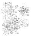
- Fig. 2 is a diagrammatic perspective view showing the various operations of the current pickup assemblies in conjunction with a guide assembly according to the present invention;
- Fig. 3 is a diagrammatic perspective view showing the operation of the control shaft and connecting rod according to the present invention;
- Fig. 4 is a cross-sectional perspective view of a typical drive means and variable displacement means according to the present invention;
- Fig. 5 is an exploded perspective view of a guide assembly housing a current pickup assembly according to the present invention;
- Fig. 6 is an exploded perspective view of the guide assembly shown in Fig. 5 according to the present invention;
- Fig. 7 is a cross-sectional view showing a current pickup assembly using one type of gimball means in conjunction with the guide assembly, variable displacement means, and drive means according to the present invention;
- Fig. 8 is an exploded perspective view of another gimball means according to the present invention;
- Fig. 9 is an assembled perspective view of the gimball means shown in Fig. 8 according to the present invention;
- Fig. 10 is a perspective diagrammatic view of another gimball means according to the present invention;
- Fig. 11 is a diagrammatic perspective view of a pivot means in conjunction with a rotation means according to the present invention;
- Fig. 12 is a perspective diagrammatic view of another pivot means and rotation means according to the present invention;
- Fig. 13 is a perspective view of a typical guide assembly post guide member according to the present invention;
- Fig. 14 is a cross-sectional view of the post guide member shown in Fig. 13;
- Fig. 15 is a cross-sectional view of a nut member assembled on the post guide member at the end of a barrel according to the present invention;
- Figures 16 and 17 are partial cross-sectional views of the nut member shown in Fig. 15 and showing the fluid vanes thereon according to the present invention shown; in Fig. 17, however, depicting an enlarged conical outlet bore; and,
- Fig. 18 is a cross-sectional view of the nut member taken along
line 18 of Fig. 16 according to the present invention. - Corresponding reference characters indicate corresponding parts throughout the several views of the drawings.
- The exemplifications set out herein illustrate preferred embodiments of the invention in one form thereof and such exemplifications are not to be construed as limiting the scope of the disclosure or the scope of the invention in any manner.
- The specific embodiments, as shown in the figures, relate to current pickup assemblies for placing electric current on an electrical discharge machine apparatus moving wire electrode, as well as guide assemblies for guiding an electrical discharge machine apparatus moving wire electrode.
- As shown in Fig. 1, an electrical discharge machine, generally indicated as 10, utilizes a
wire electrode 12 wrapped around spools 14.Spools 14 are rotated andwire electrode 12 travels therebetween. Wire guide assemblies generally indicated as 16, are mounted on the ends ofarms 18.Wire electrode 12 is received throughassemblies 16 and is guided thereby.Workpiece 20, generally made of a conductive material, is held on table 22 so that it may be cut and/or shaped by the movingwire electrode 12. More specifically,arms 18 and/or table 22 are moved with respect to one another so thatwire electrode 12 may travel throughworkpiece 20 cutting and shaping the same in a predetermined desired manner.Arms 18 may be displaced with respect to one another and also thereby cuttingworkpiece 20 at a given desired angle. The cutting and shaping ofworkpiece 20 is caused by the movingwire electrode 12 as it travels betweenspools 14 by the placement of a different electrical potential onwire 12 andworkpiece 20, thereby causing a spark therebetween andelectroeroding workpiece 20 in the proximity of the travelingwire electrode 12. - The working features of the current pickup assemblies are diagrammatically shown in Figs. 2 and 3 whereat the X, Y, and Z axes are utilized depicting a three dimensional or perspective diagram. The Z axis defines the normal straight line of travel for moving
wire electrode 12 betweenpre guide member 24 and postguide member 26.Pre guide member 24 includes a bore orhole 28 therethrough and postguide member 26 also includes a bore orhole 30 therethrough.Bores wire electrode 12 and guiding the same along the Z axis or the normal straight line of travel.Pre guide member 24 is affixed and supported onpre guide support 32 and postguide member 26 is affixed and supported onpost guide support 34. A conductive body is depicted in dashed lines and as having a generallycylindrical shape 36.Conductive body 36 is preferably made of tungsten or tungsten carbide.Conductive body 36 includes abore 38 longitudinally throughconductive body 36 and having a longitudinal axis R. Conductive body bore 38 is also depicted in dashed lines and is also depicted as being curvilinear in cross section and cylindrically shaped, increasing in diameter outwardly from the longitudinal midpoint, here shown as the intersection between the X and Y axes. Thus, acontact wall 40 is provided inconductive body 36 here depicted as the wall of conductive body bore 38.Conductive body 36 is electrically connected to a power source (not shown) and transfers or places electrical current onwire electrode 12 aswire electrode 12 rubs or slides against and contacts contactwall 40. - In a first embodiment, according to the present invention, conductive body bore longitudinal axis R is situated at an angle alpha (α) with respect to the Z axis or the normal straight line of wire travel. In this embodiment, angle α is fixed and
wire electrode 12 travels throughbore 38 and, under normal tension,wire electrode 12contacts contact wall 40 on one side at one end ofmidpoint 42 and contacts contactwall 40 on the other side at the other end ofmidpoint 42. Therefore, deformation or curl ofwire electrode 12 is substantially minimized and, thus, cutting accuracy is increased. So as to further minimize deformation or curl ofwire electrode 12,guide members midpoint 42. In this fashion, the tension inwire electrode 12 on both sides ofmidpoint 42 is substantially equal and, also, the rubbing or contact surface betweenwire electrode 12 andcontact wall 40 is substantially equal on both sides ofmidpoint 42, thus, equally cancelling any deformation onwire electrode 12 caused by the rubbing thereof againstcontact wall 40. So as to maximize the useful life ofconductive body 36, there is provided a means for rotatingconductive body 36 about bore longitudinal axis R as indicated byarrows 44. The means for rotating can be manual or automated. Further, the rotation ofconductive body 38 can be linear, thus, causing substantially even wear oncontact wall 40 or, in the alternative, can be incremental. - In a second embodiment, a pivot means is provided for supporting
conductive body 36 and selectively pivoting the conductive body bore axis R at any desired angle α with respect to the normal straight line of wire travel or the Z axis. In this second embodiment, the benefits of the above-discussed first embodiment are attained. Further, conductive body bore longitudinal axis R can selectively be situated collinear with the Z axis, thus, making manual and/or automatic threading ofwire electrode 12 substantially easier. By selectively increasing angle α between longitudinal bore axis R and the Z axis, the tension onwire electrode 12 can also be selectively increased or decreased, thus, also providing selective control of the electrical transfer betweencontact wall 40 andwire electrode 12 and selective control of the wear ofcontact wall 40. As with the above-discussed first embodiment, a means for rotatingconductive body 36 may also be provided with the second embodiment, thus, substantially fully utilizingcontact wall 40 and increasing the useful life thereof. Various means for pivoting and rotating are described hereinbelow. - In yet a third embodiment of the current pickup assembly, a gimball means is provided for supporting
conductive body 36 and selectively gimballing the bore longitudinal axis R aboutmidpoint 42. Thus, bore longitudinal axis R may be pivoted about mutually perpendicular and intersecting axes X and Y at a given angle α in an infinite number of planes parallel with the Z axis. As shown in Fig. 3, acontrol shaft 46 is connected toconductive body 36. By rotatingcontrol shaft 46, as indicated byarrows 48 and pivoting or causing cantilever movement ofcontrol shaft 46, as indicated byarrows 50, conductive body bore longitudinal axis R can selectively be placed at any given angle α and in any plane that is parallel with the Z axis. Further, by preprogrammed control of the rotational and cantilever movement ofcontrol shaft 46 as described hereinbelow, bore longitudinal axis R can be caused to pivot about the X and Y axes so as to rotate about the Z axis as indicated by the dashed ring lines oftravel 52 at any given angle α. Accordingly, all the advantages discussed hereinabove with respect to the first and second current pickup assembly embodiments are attained also by this third embodiment. The preprogrammed control ofcontrol shaft 46 is achieved with a connectingrod member 54. Connectingrod 54 includes afirst end 56 engagingcontrol shaft 46 and asecond end 58 pivotally connected to a drive means atpivotal point connection 64. The drive means rotationally moves connecting rodsecond end 58 about drive meansaxis 60 as shown in dashedline circle 62.Connecting rod member 54 further includesfront face 66 and back face 68. At thefirst end 56 of connectingrod 54, a generally square aperture orwindow 70 is provided through connectingrod member 54 with openings infaces control shaft 46 is generally square and is received insquare aperture 70. Between faces 66 and 68, there are also provided connecting rod cam surfaces 72 slidingly engagingcam walls 74, shown in Fig. 3 in dashed lines. - Upon rotational movement of
second end 58 of connectingrod 54 aboutpivot point 64 via the drive means, about the drive meansaxis 60 as indicated byarrows 76, through the engagement ofcontrol shaft 46 with connectingrod 54 inaperture 70,control shaft 46 is both rotated as indicated byarrows 48 and moved upward and downward in a cantilever fashion as indicated byarrows 50. Depending on the radial distance between drive meansaxis 60 andpivot point connection 64,control shaft 46 is pivoted as indicated byarrows 48 at an angle beta β. Accordingly, through the rotational movement of thesecond end 58 of connectingrod 54 about drive meansaxis 60, conductive body longitudinal bore R is rotated about the Z axis or the wire electrode normal straight line of travel as indicated by dashed ring lines oftravel 52. Furthermore, angle β is proportional to angle α and by selectively radially displacingpivot point connection 64 from drive meansaxis 60, angle α and the radial displacement of longitudinal bore axis R as indicated by dashedlines 52 can be selectively controlled. - The radial displacement between drive means
axis 60 andpivot point connection 64 is selectively controlled via a variable radial displacement means located between the drive means and connectingrod 54. As shown in Figs. 4 and 7, a plunger generally indicated as 78 is received in sleeve orcylindrical opening 80.Plunger 78 has an exteriorcylindrical surface 82 and is adapted for reciprocal and rotational movement insleeve 80.Plunger 78 includes afirst end 84 and asecond end 86.Plunger 78 is rotatably driven at itssecond end 86 thereof by a drive means or motor M through a longitudinally expandable coupling generally indicated as 88.Coupling 88 includes asquare shaft 90 connected to plunger 78 at itssecond end 86 and acoupling member 92 connected to motor M viamotor shaft 94 and rotatably driven by motor M as indicated byarrows 96. Couplingmember 92 includes a longitudinal square hollow coaxially aligned with drive meansaxis 60 and adapted to reciprocally receivesquare shaft 90 therein. Thus,plunger 78 can be reciprocally moved along drive meansaxis 60 withinsleeve 80 as indicated byarrows 100 while rotatably driven via longitudinallyexpandable coupling 88 and motor M. - The reciprocal movement of
plunger 78 can be controlled manually or automatically and a typical manual plunger reciprocal movement control is shown in Figs. 4 and 7. More specifically,plunger 78 includesannular rings 102 near thesecond end 86 and defining anannular groove 104 therebetween. Anadjustment screw 106 is journalled inbores support structure 112.Adjustment screw 106 includes acontrol knob 114 and a threadedportion 116threadingly engaging ear 118.Ear 118 includes a threadedbore 120 for threadingly receiving threadedportion 116 ofadjustment screw 106 and, further, includes atongue portion 122 received withinannular groove 104.Tongue portion 122 slidingly engagesannular rings 102 asplunger 78 is rotated about drive meansaxis 60, thus, by selectively rotatingadjustable screw 106 as indicated byarrows 124,ear 118 is selectively reciprocated thereby also causingplunger 78 to be selectively reciprocally moved along drive meansaxis 60. - It is contemplated that various other means can be provided for moving
plunger 78 reciprocally along drive meansaxis 60. For example,plunger 78 can be housed in a pneumatic cylinder and air pressure supplied selectively within the pneumatic cylinder in chambers formed on theends plunger 78 thereby selectively reciprocatingplunger 78 therein. Further, in such pneumatic embodiment, a stop can be incorporated for selectively placingplunger 78 at a desired longitudinal position within the pneumatic cylinder at the end of the particular stroke thereof and, thus, controlling the radial displacement between drive meansaxis 60 andpivot point connection 64. - At the
first end 84 ofplunger 78, there is provided adrive shaft 126 having a first end indicated as 128 and a second end indicated as 130. A drive shaft bore 132 is provided inplunger 78 extending therein fromface 134 ofplunger 78. Drive shaft bore 132 is substantially square shaped with a longitudinal drive shaft boreaxis 136 situated at an angle with respect to drive meansaxis 60 and intersecting therewith at apoint 138. Driveshaft 126 is also substantially square shaped and is adapted to be slidingly received in drive shaft bore 132. - At the
first end 128,drive shaft 126 is pivotally connected to connectingrod 54 aboutpivot point 64. This pivotal connection is adapted to prevent longitudinal movement thereat ofdrive shaft 126 via retention rings 140 and/or by other suitable means.Cylindrical shaft 142 is journalled incylindrical hole 144 for pivotal movement therebetween as described hereinabove. Accordingly, reciprocal longitudinal movement ofplunger 78 causes reciprocal sliding ofdrive shaft 126 within drive shaft bore 132 and, thereby, providing selective radial displacement ofpivotal point connection 64 from drive meansaxis 60. More specifically, movement ofplunger 78 away from connectingrod 54 causes the greatest radial displacement while movement ofplunger 78 towards connectingrod 54 coaxially alignspivotal point connection 64 with drive meansaxis 60. Thus, the movement ofplunger 78 away from connectingrod 54 increases angle α between the normal straight line of wire travel and the longitudinal bore axis R ofconductive body 36 while situatingpoint 64 coaxial with drive meansaxis 60, also coaxially aligns longitudinal bore axis R with the normal straight line of wire travel. - The various current pickup assemblies are received and supported within a
barrel 146 and are adapted to work in conjunction withwire guide assemblies 16. More specifically,wire guide assemblies 16 include a first guide member or means 148 also referred to as the final guide and having abore 150 therethrough, a second guide member or means 152 also referred to as the post guide and having abore 154 therethrough and, a third guide member or means 156 also referred to as the pre guide and having abore 158 therethrough.Bores wire electrode 12 therethrough and guide the wire in the normal straight line of wire travel. The various current pickup assemblies are located between second guide or postguide member 152 and third guide orpre guide member 156 and first guide orfinal guide member 148 is located on the working end ofguide assembly 16 or closest to workpiece 18. -
Post guide 26 includes a postguide holder body 160 having awire passageway 162 therethrough between afirst opening 164 and asecond opening 166. Postguide holder body 160 includes an enlarged portion generally indicated as 168 and a thinner portion generally indicated as 170.Enlarged portion 168 includes outer frusto-conically shapedwalls 172 andfluid channels 176 extending generally longitudinally thereon. A guide support is provided onbarrel 146 and, more specifically, at one end ofbarrel 146. A frusto-conicalinner surface 176 is formed converging toward a hole or opening 178.Enlarged portion 168 of postguide holder body 160 is larger than guide support hole 178 andwalls 172 thereof seat against frusto-conicalinner surface 176 and, thus, also formfluid channels 174 therebetween. However,thinner portion 170 of postguide holder body 160 is smaller than guide support hole 178 and is, thus, received therethrough as shown.Threads 180 are provided onthinner portion 170 and a guide nut means or member 182 includesthreads 184 adapted for mating engagement with thethinner portion threads 180. Accordingly, upon mating engagement ofnut member threads 184 withthinner portion threads 180, nut member annular flat 186 is forced against annular flat 188, compressing O-ring member 190 and, in a clamping fashion, lockingguide holder body 160 and nut member 182 upon frusto-conical end 192 ofbarrel 146. - As more clearly shown in Fig. 14, guide
body 16 includes a first counter bore 194 communicating withpassageway 162 throughfirst opening 164 and, also, includes a second counter bore 196 communicating withpassageway 162 throughsecond opening 166.Guide members respective counterbores material 198. Mountingmaterial 198 substantially surrounds the guide members andconical passageways 200 are formed therein converging towardsbores respective guide members members material 198 is made of sintered metal.Guide holder body 160 is preferably made of stainless steel. -
Second guide member 152, in the alternative, can be fixed or mounted to guideholder body 160 via aplug 202 as shown in Figs. 6 and 7.Plug 202 includes an exterior threadedsurface 204 threadingly received in threadedcylindrical bore 206.Plug 202 includes a wire passageway having a counterbore or boreportion 208 whereinsecond guide member 152 is mounted in a mountingmaterial 198 as described hereinabove with respect to Fig. 14. Plug 202 further includes tool holes 210 for receiving a mating tool androtating plug 202 for threadingly engagingthreads 206.Plug 202 is preferably made of stainless steel. - Guide nut member 182, in addition to locking
guide holder body 160 to the end ofbarrel 146, aids in the automatic threading of awire electrode 12 throughguide assembly 16 and/or aids in the flushing ofworkpiece 18. In this regard, guide nut member 182 includes ahousing 212 defining afluid passageway 214 substantially surrounding guide bodythinner portion 170. A plurality ofinlet ports 216 are provided throughhousing 212 and communicating withfluid passageway 214 and, also, anoutlet port 218 is provided and communicates withfluid passageway 214. When guide nut member 182 is threadingly received on post guidethinner portion 170,channels 174, defined inenlarged portion 168 ofguide holder body 160, are aligned withfluid inlet ports 216. Further, a plurality of threadingfluid ports 220 are provided inbarrel 146 and communicating with anannular fluid passageway 222 formed betweensleeve member 224 and theinterior surface 226 ofbarrel 146. Annularfluid passageway 222 includes acurvilinear wall 228 for providing a smooth transition of fluid from threadingfluid ports 220 tochannels 174. For creating a threading or flushing jet atoutlet port 218, a fluid such as deionized water under pressure, is forced as indicated by arrows A through threadingfluid ports 220 aroundannular fluid passageway 222 intochannels 174 and alignedinlet port 216 of nut member 182 intofluid passageway 214 and out throughoutlet port 218. Thus,outlet port 218 receives therethrough bothwire electrode 12 and a threading or flushing fluid. - In an alternative embodiment of guide nut member 182, as shown in Figs. 6 and 15-18,
threads 184 andinlet ports 216 are formed incross member 230.Cross member 230 is frictionally forced or press fit inbore 232 or affixed therein by any other suitable means. Thus, fluid received inchannels 174, as shown in Fig. 15, travels throughinlet ports 216 intofluid passageway 214 and out through outlet bore 218. - So as to provide substantially laminar fluid flow out through
outlet port 218,ports 220,channels 174,inlet ports 216,fluid passageway 214, andoutlet port 218, are sized so as to continually and gradually decrease in fluid flow area. Furthermore, as shown in Figs. 15-18,fluid passageway 214 is provided withfluid vanes 234 and defining radialfluid passageways 236 wherethrough the threading fluid flows fromfluid passageway 214 and out throughoutlet port 218.Vanes 234 may include aland 238 whereupon guide bodythinner portion 170 may rest. - As shown in Fig. 17,
outlet port 218 may include an enlarged frusto-conical portion 240 whereby during automatic threading, awire electrode 12 being received throughoutlet 218, as indicated by arrow B, is aided in finding its way into thebore 150 offirst guide member 148. - At the frusto-
conical end 192 ofbarrel 146 there is also provided aflushing nozzle 242 having a threadedinterior bore 244 for mating engagement withthreads 246 ofbarrel 146. Flushingnozzle 242 includes a flushingfluid inlet 248, aconical passageway 250 surroundingpost guide member 26 and aflushing outlet port 252. Flushing fluid is thus received innozzle 242 throughinlet 248 intoconical passageway 250 and out through flushingoutlet port 252 and ontoworkpiece 18 thereby flushing the same. -
Barrel 146, at the other end of frusto-conical end 192 includes a threadedinterior surface portion 254. Acylindrical member 256 havingexterior surface threads 258 is threadingly received inbarrel 146 and engagingthreads 254.Cylindrical member 256 includes anannular lip 260 adapted to rest onannular seat 262 thereby positively longitudinally placingthird guide member 156. A wire passageway including threadedbore 264 is provided incylindrical member 256 and aplug 270 is threadingly received therein.Plug 270 is identical to plug 202 except thatthird guide member 156, made of the same materials asmembers conical portion 272 is formed incylindrical member 256 and leads toconical passageway 200 formed in mountingmaterial 198. Tool holes 274 are also provided incylindrical member 256 for twisting and threadingly engagingcylindrical member 256 withinbarrel 146. Further, outlet bores 276 shown in Fig. 6 extend longitudinally throughcylindrical member 256 and allow gases and/or fluid to exit from withinbarrel 146. - The various current pickup assemblies are situated within
barrel 146 betweensecond guide member 152 andthird guide member 156 and with acontrol shaft 46 extending through alongitudinal bore 278 on the wall ofbarrel 146. As shown in Fig. 5,barrel 146 can be retained or fixed on anarm 18 by clampingbarrel 146 betweenarm 18 andsupport structure 112.Support structure 112 is affixed toarm 18 via threadedscrews 278 received throughholes 280 insupport structure 112 and threadingly engaged in threadedholes 282 inarm 18. As shown,cam walls 74 are formed insupport structure 112 and connectingrod 54 engagingcontrol shaft 46 is cammed thereagainst. In Fig. 5, the above-discussed radial displacement means and drive means are diagrammatically indicated as 284. - For aiding the smooth movement of
control shaft 46 as indicated byarrows control shaft 46 received withinsquare aperture 70 of connectingrod 54 are rounded as indicated at 286. Further, a threadedscrew 288 is received through alongitudinal bore 290 and used to securecontrol shaft 46 toconductive body 36 and/or the various current pickup assemblies. - The various means for rotating, means for pivoting, and gimball means are described hereinafter. A first gimball means is shown in Fig. 7 wherein a ball or
sphere 292 is journalled in a socket means andconductive body 36 is fixed in abore 294 extending throughball 292. The socket means includes a first annularcurvilinear surface 296 formed insleeve member 224. Withinsleeve member 224 there is also receivedring member 298 wherein there is formed second annularcurvilinear surface 300. Asecond ring member 302 threaded on itsexterior surface 304 threadingly engages interior threadedsurface 306 ofsleeve 224. Acompression spring 308 having an outer diameter smaller than the inside diameter ofsleeve 224 is received betweenfirst ring member 298 andsecond ring member 302 and serves to pushring member 298 againstball 292, thus,journalling ball 292 betweensurfaces sleeve 224 two ring members having annular curvilinear surfaces can be used forjournalling ball 292 and a compression spring situated betweencylindrical member 256 and one of the ring members. -
Ball 292 further includes a threadedbore 310 for threadingly receivingscrew 288 and attachingcontrol shaft 46 thereon. Thus, through rotational movement as indicated byarrows 48 and cantilever movement as indicated byarrows 50,current pickup body 36 is pivoted about the X and Y axes as described hereinabove. It should also be noted that an electrical power supply is connected to barrel 146 (not shown) and becausebarrel 146,sleeve 224,ball 292 andconductive body 36 are made of conductive materials, current is transferred and placed onwire electrode 12 as it contacts contactwall 40. - In Fig. 10, there is shown an alternate gimball means. More specifically, a
conductive body holder 312 is provided for receiving therein aconductive body 36 and retained therein with acap 314.Cap 314 hasthreads 316threadingly engaging threads 318 withinconductive body holder 312.Cap 314 includes anopening 320 and the other end ofconductive body holder 312 also has an opening (not shown) and, thus,wire electrode 12 travels throughcap 314,conductive body 36 andconductive body holder 312. -
Conductive body 312 is connected to controlshaft 46 at 322 and is connected to stud 324 at 326.Control shaft 46 and stud 324 are pivotally connected or journalled at 328 and 330 respectively to ringmember 332. Thus, rotational movement ofcontrol shaft 46, as indicated byarrows 48, causes pivotal movement ofconductive body holder 312 about the Y axis. - Along the X axis, there are provided
shaft members 334 which are connected to ringmember 332.Shaft members 334 are pivotally connected at 336 in a support assembly generally indicated as 338 and which can be inbarrel 146. Accordingly, cantilever movement ofcontrol shaft 46 as indicated byarrows 50 causes pivotal movement ofconductive body holder 312 about the X axis as indicated byarrows 340.Shaft members 334,control shaft 46, stud 324 andconductive body holder 312 are made of conductive materials and electrical current can, thus, be transferred toconductive body 36 by applying current toshaft members 334 throughsupport assembly 338. In the alternative, a braided wire or the like can be attached toconductive body holder 312 and connected to the power source. It should also be noted thatconductive body 36 can itself be pivotally connected to ringmember 332 without utilizingconductive body holder 312. - In yet a different gimball means, as shown in Figs. 6, 8, and 9, a first
annular member 342 is supported in a support assembly such as withinbarrel 146. Firstannular member 342 includes anotch 344 and aninner bore 346. A first spring means such asleaf springs 347 are connected at their first end 348 at 350 to firstannular member 342.Connections 350 can be a longitudinal slot cut into firstannular member 342 and receiving first end 348 ofleaf spring 347. Leaf springs 347 extend longitudinally from firstannular member 342 and are adapted for cantilever movement at theirsecond end 352 with respect to the first annular member in a first plane or generally about a line formed betweenconnections 350 ofleaf springs 347 to firstannular member 342. A secondannular member 354 is generally oval-shaped and has aninner cavity 356. Secondannular member 354 is connected toleaf springs 347 at their second ends 352 thereof at the longitudinal ends 358 of secondannular member 354. Secondannular member 354 also includes anotch 360 located longitudinally abovenotch 344. - Second spring means or two
other leaf springs 362 are connected to the secondannular member 354 at 364.Connections 364 ofleaf springs 362 are identical toconnections 350 andleaf springs 362 extend longitudinally therefrom towards firstannular member 342 and, because secondannular member 354 is oval-shaped andconnections 364 are at the shortest radial distance from the Z axis,leaf springs 362 extend to withininner bore 346 of firstannular member 342. Accordingly, the second ends 366 are adapted for cantilever movement about a line defined betweenconnections 364 in a second plane perpendicular to the first plane. - A third
annular member 368 is connected toleaf springs 362 atconnections 370 in a similar fashion asconnections 350. Thirdannular member 368 includes a conductive body receiving bore 372 adapted to receive therein conductive body orpickup 36. An L-shapedarm 374 is connected to thirdannular member 368 and includes a threadedhole 376 through L-shapedarm 374 and thirdannular member 368. Asmall screw 378 is received in and through threadedhole 376 and whenconductive body 36 is situated within thirdannular member 368 as shown in Fig. 9, serves to lock or clampconductive body 36 within thirdannular member 368. At the other end of L-shapedarm 374, there is a threadedhole 380 and a screwdriver-type groove 382. Anelongate projection 384 is provided on the end ofcontrol shaft 46 and is adapted to be received ingroove 382.Screw 288 is received throughlongitudinal bore 290 ofcontrol shaft 46 and threadingly engages threadedhole 380 for connectingcontrol shaft 46 to L-shapedarm 374.Elongate projection 384 and groove 382 prevent rotational slippage ofcontrol shaft 46 when control shaft is pivoted as indicated byarrows 48. - Accordingly, rotational movement of
control shaft 46 causesconductive body 36 to pivot about the Y axis while cantilever movement ofcontrol shaft 46 causesconductive body 36 to pivot about the X axis. Asleeve member 386 is received over secondannular member 354 and enclosing the same as shown in Fig. 6 without preventing the gimballing movement ofconductive body 36.Sleeve member 386 includes anotch 388 aligned withnotch 344 of firstannular member 342 and, thus, providing an openingwherethrough control shaft 46 is connected to L-shapedarm 374. - This gimballing means utilizing spring means provides pivotal movement of
conductive body 36 about two perpendicular and intersecting axes as with the other gimball means. Further, current is placed on firstannular member 342 by contacting the support structure orbarrel 146 and is advantageously delivered toconductive body 36 with constant positive electrical connections and without having to pass through any pivotal or journalled connections. - In Figs. 11 and 12, there are shown the preferred second embodiments of the current pickup assemblies wherein a pivot means is provided for supporting
conductive body 36 and selectively pivoting the same about the X axis as indicated byarrows 390. More specifically, aring member 392 having anannular groove 394 is connected toshaft members 334.Shaft members 334 are pivotally connected at 336 to a support structure or assembly diagrammatically shown as 338 and which can be, for example,barrel 146.Conductive body holder 312 and/orconductive body 36 are connected to an annular washer orjournal member 396 journalled inannular groove 394 and thereby providing rotational movement ofconductive body holder 312 and/orconductive body 36 about the longitudinal bore axis R as indicated byarrows 44. - In Fig. 11, a
worm gear 398 is formed or connected toconductive body 36 orholder 312 and amating worm 400 is connected to or formed oncontrol shaft 46.Control shaft 46 is pivotally connected to ringmember 392 in twoholes 402 and, thus, placingworm 400 in mating engagement withworm gear 398. By rotatingcontrol shaft 46, as indicated byarrows 48,conductive body 36 orholder 312 may be pivoted about bore longitudinal axis R as indicated byarrows 44. Further, cantilever movement ofcontrol shaft 46 as indicated byarrows 50, causesring member 392,conductive body 362, orholder 312 and the body longitudinal axis R to pivot about the X axis and, thus, placing the bore longitudinal axis R at an angle α with respect to the normal straight line of wire travel. - In Fig. 12, a bevel gear 404 is connected to or formed on annular washer or
journal member 396 and amating pinion 406 is formed or connected to controlshaft 46.Control shaft 46 is pivotally connected or journalled inhole 408 and places pinion 406 in mating engagement with bevel gear 404. As described with respect to Fig. 11, rotational and cantilever movement ofcontrol shaft 46 pivotsconductive body 36 orholder 312 about the X axis and rotates the same about longitudinal bore axis R.
Claims (19)
- Electrical discharge machine with a current pickup assembly for placing electric current on a moving wire (12) electrode having a normal straight line (Z) of travel through said current pickup assembly, wherein the assembly comprises a conductive body (36) with a bore (38) for receiving the wire (12) electrode therethrough, said bore (38) having a longitudinal axis (R) and a wire contact wall (40) wherein the bore (38) longitudinal axis (R) is placed at an angle (α) with respect to the normal straight line (Z) of wire travel whereby the moving wire (12) electrode contacts said contact wall (40), characterized ina) means (46,48,398,400,404,406) for rotating said body (36) about said longitudinal axis (R) of said bore (38); and/orb) pivot means (46,48,54,60,62,64,292,246,300,324,334, 362) for supporting said body (36) and selectively adjusting said angle (α) with respect to the normal straight line (Z) of wire (12) travel.
- Machine according to claim 1, characterized in a pre guide member (24,156) with a guide bore (28,158) on one side of said body (36) and a post guide member (26,152) with a guide bore (30,154) on the other side of said body, wherein said pre and post guide members (24,26,152,156) guide the wire (12) electrode in the normal straight line (Z) of travel.
- Machine according to claim 1 or 2, characterized in comprising a final guide member (148) with a guide bore (150) located on one side of said post guide member (26,152) opposite said body (36), wherein said final guide member is also guiding the wire electrode through said final guide bore (150) in the normal straight line (Z) of travel.
- Machine according to claim 2 or 3, characterized in that said guide members (152,156,148) each include a diamond portion comprising said guide bore (154,158,150) therein.
- Machine according to one of the claims 1 to 4, characterized in that the bore longitudinal axis (R) intersects the normal straight line (Z) of travel substantially at a longitudinal midpoint (42) of said bore (38), whereby in cross-section, the wire (12) electrode contacts said contact wall (40) on one side at one end of said midpoint and contacts said contact wall on the other side at the other end of said midpoint, wherein the distances from said midpoint (42) of said bore (38) to said pre and post guide members (156,152) are preferably substantially equal.
- Machine according to claim 5, characterized in that said bore contact wall (40) is curvilinear in cross-section, said bore (38) being cylindrically shaped and increasing in diameter outwardly from said midpoint (42).
- Machine according to one of the claims 1 to 6, characterized in that the pivot means (46,48,54,60,62,64;292,296,300,324,334,362) includes a ring member (392) pivotally supported in a support assembly (338) and wherein said rotating means includes a journal member (396) rotatably connecting said body (36) in said ring (392).
- Machine according to claim 7, characterized in that rotating means further includes a worm gear (398) on said body (36) and a mating worm (400) on a control shaft (46), which is also pivotally connected to said ring member (392), whereby rotation (48) of said control shaft (46) causes said body (36) to rotate about said bore longitudinal axis (R) and cantilever movement (50) of said control shaft (46) causes said ring member (392), body (36) and body longitudinal axis (R) to pivot and selectively place said bore longitudinal axis (R) at said angle (α) with respect to the normal straight line (Z) of wire travel.
- Machine according to claim 7, characterized in that said rotating means includes a bevel gear (404) on said journal member (396) and a mating pinion (406) on a control shaft (46), which is also pivotally connected to said ring member (392), whereby rotation (48) of said control shaft (46) causes said body (36) to rotate about said bore longitudinal axis (R) and cantilever movement (50) of said control shaft (46) causes said ring member (392), body (36) and body longitudinal axis (R) to pivot and selectively place said bore longitudinal axis (R) at said angle (α) with respect to the normal straight line (Z) of wire travel.
- Machine according to one of the claims 1 to 9, characterized in that said pivot means comprises gimball means for supporting said body (36) and selectively gimballing and pivoting said bore longitudinal axis (R) about a point (42) defined by two mutually perpendicular and intersecting axes (X,Y) of rotation.
- Machine according to claim 10, characterized in that a control shaft (46) is connected to said body (36), whereby rotation (48) of said shaft (46) causes said body (36) longitudinal axis (R) to pivot about one axis (Y) of said perpendicular and intersecting axes (X,Y) and cantilever movement (50) of said control shaft (46) causes said body longitudinal axis (R) to pivot about the other axis (X) of said perpendicular and intersecting axes (X,Y).
- Machine according to claim 11, characterized in comprising a connecting rod (54) cammed between two cam walls (74) and having a first end (56) engaging said control shaft (46) and said second end (58) being pivotally connected to a drive means (60,62) for rotational movement of said second end of said connecting rod (54) about a drive means axis (60) and, wherein said rotational movement (62) of said second end (58) of said connecting rod (54) causes simultaneous rotational and cantilever movement of said control shaft (46) and rotation of said bore longitudinal axis (R) about said wire electrode normal straight line (Z) of travel.
- Machine according to claim 12, characterized in comprising variable radial displacement means (78,80,82, 136,106,114,118,102) between said drive means (60) and said connecting rod (54) for selectively radially displacing said drive means axis (60) and, wherein when said pivotal connection (64) is coaxial with said drive means axis (60), said conductive body bore longitudinal axis (R) and the wire electrode normal straight line (Z) of travel are co-linear.
- Machine according to claim 13, characterized in that said radial displacement means includes a plunger (78) received in and adapted for reciprocal and rotational movement in a sleeve (80) and being rotatably driven at one end (86) thereof by said drive means (M,60) through a longitudinally expandable coupling (88), and including a drive shaft (126) pivotally connected at one end (128) to said connecting rod (54) second end (58) pivotal connection and slidingly received in a drive shaft bore (132) extending in said plunger (78) at the other end of said coupling (88), said drive shaft bore (132) having an axis (136) at an angle with respect to said drive means axis (60) whereby reciprocal movement (100) of said plunger (78) in said sleeve (80) causes reciprocal movement of said drive shaft (126) in said drive shaft bore (132) and radial displacement of said connecting rod (54) second end (58) pivotal connection (64) from said drive means axis (60).
- Machine according to claim 10, characterized in that gimball means includes a ring member (332) pivotally supported in a support assembly (338) about one axis (X) of said perpendicular and intersecting axes (X,Y) and said body (36) is pivotally supported in said ring member (332) on a control shaft (46) about the other axis (Y) of said perpendicular and intersecting axes (X,Y), whereby rotation (48) of said control shaft (46) causes said body (36) longitudinal axis (R) to pivot about one axis (Y) of said perpendicular and intersecting axes (X,Y) and cantilever movement (50) of said control shaft (46) causes said body (36) longitudinal axis (R) to pivot about the other axis (X) of said perpendicular and intersecting axes (X,Y).
- Machine according to claim 15, characterized in that said bore longitudinal axis (R) intersects the normal straight line (Z) of the wire travel at said point (42) whereat said two mentually perpendicular and intersecting axes (X,Y) intersect, whereby in cross-section the wire (12) electrode contacts said contact wall (40) on one side at one end of said point (42) and contacts said contact wall (40) on the other side of said point (42).
- Machine according to claim 10, wherein said gimball means includes:- a first annular member (342) supported in a support assembly (146);- first spring means (347) connected to said first annular member (342) at one end (348) thereof and extending longitudinally therefrom, said first spring means (347) adapted for cantilever movement at the other end (352) thereof in a first plane;- a second annular member (354) connected to said first spring means (347) at said other end (352) of said first spring means (347);- second spring means (362) connected to said second annular member (354) at one end (364) thereof and extending longitudinally therefrom and adapted for cantilever movement at the other end (366) thereof in a second plane perpendicular to said first plane; and,- wherein said conductive body (36) is connected to said second spring means (362) at said second end (366) thereof.
- Machine according to claim 17, characterized in comprising a control shaft (46) connected to said conductive body (36) and whereby rotation (48) of said shaft (46) causes said body (36) longitudinal axis (R) to pivot about one axis (Y) of said perpendicular and intersecting axes (X,Y) and cantilever movement (50) of said control shaft (46) causes said body (36) longitudinal axis (R) to pivot about the other axis (X) of said perpendicular and intersecting axes (X,Y).
- Machine according to claim 10, characterized in that said gimball means includes a ball (292) having a center point (42) journalled in a socket means (224), said conductive body (36) attached to said ball (292) with said bore longitudinal axis (R) intersecting said ball center point (42).
Applications Claiming Priority (3)
| Application Number | Priority Date | Filing Date | Title |
|---|---|---|---|
| US07/325,283 US4994643A (en) | 1989-03-17 | 1989-03-17 | Electrical discharge machine apparatus tilted current pickup |
| US325283 | 1989-03-17 | ||
| PCT/US1990/001359 WO1990011158A1 (en) | 1989-03-17 | 1990-03-13 | Electrical discharge machine apparatus tilted current pickup |
Publications (3)
| Publication Number | Publication Date |
|---|---|
| EP0463066A1 EP0463066A1 (en) | 1992-01-02 |
| EP0463066A4 EP0463066A4 (en) | 1992-04-15 |
| EP0463066B1 true EP0463066B1 (en) | 1994-07-06 |
Family
ID=23267218
Family Applications (1)
| Application Number | Title | Priority Date | Filing Date |
|---|---|---|---|
| EP90905144A Expired - Lifetime EP0463066B1 (en) | 1989-03-17 | 1990-03-13 | Electrical discharge machine apparatus tilted current pickup |
Country Status (7)
| Country | Link |
|---|---|
| US (1) | US4994643A (en) |
| EP (1) | EP0463066B1 (en) |
| JP (1) | JPH06508563A (en) |
| AU (1) | AU5331290A (en) |
| CA (1) | CA2050307A1 (en) |
| DE (1) | DE69010492T2 (en) |
| WO (1) | WO1990011158A1 (en) |
Families Citing this family (8)
| Publication number | Priority date | Publication date | Assignee | Title |
|---|---|---|---|---|
| US5089680A (en) * | 1991-05-28 | 1992-02-18 | T-Star Industrial Electronics Corporation | Indexed rotatable current pick-up for a travelling wire electrical discharge machining apparatus |
| JP2671663B2 (en) | 1991-09-30 | 1997-10-29 | 三菱電機株式会社 | Wire electric discharge machine |
| US5380973A (en) * | 1992-12-23 | 1995-01-10 | Basix Technologies Ltd. | Current pickup indexing apparatus |
| US5430268A (en) * | 1992-12-23 | 1995-07-04 | Basix Technologies Ltd. | Method and apparatus for adjusting and replacing EDM components from the guide assembly working end |
| US5384444A (en) * | 1992-12-23 | 1995-01-24 | Basix Technologies Ltd. | Sleeve forming wire passageway around pickup |
| JP3731786B2 (en) * | 1998-02-19 | 2006-01-05 | 三菱電機株式会社 | Wire electrical discharge machine |
| JP5199447B1 (en) * | 2011-12-09 | 2013-05-15 | ファナック株式会社 | Wire electrical discharge machine with rotating shaft |
| DE102014100979B4 (en) | 2013-09-09 | 2018-06-21 | Norbert Griewenka | bearing bush |
Citations (2)
| Publication number | Priority date | Publication date | Assignee | Title |
|---|---|---|---|---|
| JPS5682133A (en) * | 1979-12-04 | 1981-07-04 | Mitsubishi Electric Corp | Automatic wire feeder for wire cut type electric electric discharge machining device |
| JPS6176216A (en) * | 1984-09-20 | 1986-04-18 | Mitsubishi Electric Corp | Wire electric discharge machining device |
Family Cites Families (14)
| Publication number | Priority date | Publication date | Assignee | Title |
|---|---|---|---|---|
| US2066588A (en) * | 1933-02-15 | 1937-01-05 | Kapeila Ltd | Method and apparatus for electrical etching |
| US2974216A (en) * | 1959-01-05 | 1961-03-07 | Inoue Kiyoshi | Spark discharge contouring machine using wire electrode |
| CH571380A5 (en) * | 1973-08-06 | 1976-01-15 | Charmilles Sa Ateliers | |
| JPS5676337A (en) * | 1979-11-21 | 1981-06-23 | Mitsubishi Electric Corp | Wire cut discharge type machining device |
| DE3317826C2 (en) * | 1982-05-19 | 1994-04-07 | Amada Co | Cutting wire spark erosion machine |
| JPS58206318A (en) * | 1982-05-25 | 1983-12-01 | Mitsubishi Electric Corp | Wire cut discharge machining device |
| US4453070A (en) * | 1982-07-06 | 1984-06-05 | Ateliers Des Charmilles S.A. | Apparatus for orienting the wire electrode support and guide member and the machining fluid nozzle of a travelling wire EDM apparatus |
| JPS6080525A (en) * | 1983-10-11 | 1985-05-08 | Japax Inc | Machining liquid feeding device in wire-cut electric discharge machining |
| JPS60238233A (en) * | 1984-05-10 | 1985-11-27 | Mitsubishi Electric Corp | Dielectric fluid spouting device for wire electric discharge machine |
| DE3419944C1 (en) * | 1984-05-15 | 1985-11-21 | Aktiengesellschaft für industrielle Elektronik AGIE Losone bei Locarno, Losone, Locarno | Device for guiding a wire or band-shaped cutting electrode on a machine tool |
| JPS60249531A (en) * | 1984-05-21 | 1985-12-10 | Mitsubishi Electric Corp | Electricity feeding apparatus in wire-cut electric discharge machine |
| JPS61117015A (en) * | 1984-11-13 | 1986-06-04 | Mitsubishi Electric Corp | Wire electric discharge machine |
| JPS6285329U (en) * | 1985-11-14 | 1987-05-30 | ||
| JPS63102834A (en) * | 1986-10-17 | 1988-05-07 | Mitsubishi Electric Corp | Wire-cut electric discharge machining device |
-
1989
- 1989-03-17 US US07/325,283 patent/US4994643A/en not_active Expired - Fee Related
-
1990
- 1990-03-13 JP JP2505097A patent/JPH06508563A/en active Pending
- 1990-03-13 WO PCT/US1990/001359 patent/WO1990011158A1/en not_active Ceased
- 1990-03-13 DE DE69010492T patent/DE69010492T2/en not_active Expired - Fee Related
- 1990-03-13 AU AU53312/90A patent/AU5331290A/en not_active Abandoned
- 1990-03-13 EP EP90905144A patent/EP0463066B1/en not_active Expired - Lifetime
- 1990-03-13 CA CA002050307A patent/CA2050307A1/en not_active Abandoned
Patent Citations (2)
| Publication number | Priority date | Publication date | Assignee | Title |
|---|---|---|---|---|
| JPS5682133A (en) * | 1979-12-04 | 1981-07-04 | Mitsubishi Electric Corp | Automatic wire feeder for wire cut type electric electric discharge machining device |
| JPS6176216A (en) * | 1984-09-20 | 1986-04-18 | Mitsubishi Electric Corp | Wire electric discharge machining device |
Also Published As
| Publication number | Publication date |
|---|---|
| WO1990011158A1 (en) | 1990-10-04 |
| AU5331290A (en) | 1990-10-22 |
| DE69010492D1 (en) | 1994-08-11 |
| US4994643A (en) | 1991-02-19 |
| JPH06508563A (en) | 1994-09-29 |
| EP0463066A1 (en) | 1992-01-02 |
| CA2050307A1 (en) | 1990-09-18 |
| DE69010492T2 (en) | 1994-10-27 |
| EP0463066A4 (en) | 1992-04-15 |
Similar Documents
| Publication | Publication Date | Title |
|---|---|---|
| US4994643A (en) | Electrical discharge machine apparatus tilted current pickup | |
| EP0463103B1 (en) | Electrical discharge machine apparatus moving wire electrode guide assembly | |
| US5214260A (en) | Electrical discharge machine wire electrode guiding device | |
| US4825678A (en) | Three-dimensional bending apparatus | |
| US6370759B1 (en) | Apparatus for stripping insulation from a wire | |
| US4420671A (en) | Helicoidal guide for wire electrode of an EDM apparatus | |
| US4527035A (en) | Wire electrical discharge machine flushing process and apparatus | |
| US4483104A (en) | Drill bit sharpener | |
| US5319175A (en) | Apparatus for transferring electrical current to and from a moving wire | |
| US5324907A (en) | EDM apparatus with a cam arm for moving an electrode | |
| US4371432A (en) | Method of and apparatus for electroerosive production of profiled surfaces | |
| US5003148A (en) | Method of threading electrode through EDM guide | |
| CN211218716U (en) | Reticle device | |
| EP3981534A1 (en) | Narrow-hole electric discharge machine | |
| CN1104986C (en) | Slot Processing Machinery | |
| US5430268A (en) | Method and apparatus for adjusting and replacing EDM components from the guide assembly working end | |
| US4261142A (en) | Form relieving apparatus | |
| CN120038580B (en) | An internal support clamping assembly for clamping small hole workpieces | |
| CN213646227U (en) | Lifting type wire guide nozzle assembly for medium-speed wire cutting machine | |
| US4291580A (en) | Manometer body | |
| JP2001162449A (en) | Electrode holding device for electric discharge machine | |
| SU860980A1 (en) | Apparatus for guiding wire electrode to electric discharge cutting-out machine | |
| JPH10291112A (en) | Oil flute forming method and device for drill | |
| JPH10259494A (en) | Hollow roll carrying device |
Legal Events
| Date | Code | Title | Description |
|---|---|---|---|
| PUAI | Public reference made under article 153(3) epc to a published international application that has entered the european phase |
Free format text: ORIGINAL CODE: 0009012 |
|
| 17P | Request for examination filed |
Effective date: 19910830 |
|
| AK | Designated contracting states |
Kind code of ref document: A1 Designated state(s): CH DE ES FR GB LI NL |
|
| A4 | Supplementary search report drawn up and despatched |
Effective date: 19920227 |
|
| AK | Designated contracting states |
Kind code of ref document: A4 Designated state(s): CH DE ES FR GB LI NL |
|
| 17Q | First examination report despatched |
Effective date: 19920827 |
|
| RAP1 | Party data changed (applicant data changed or rights of an application transferred) |
Owner name: FORT WAYNE WIRE DIE, INC. |
|
| GRAA | (expected) grant |
Free format text: ORIGINAL CODE: 0009210 |
|
| AK | Designated contracting states |
Kind code of ref document: B1 Designated state(s): CH DE ES FR GB LI NL |
|
| PG25 | Lapsed in a contracting state [announced via postgrant information from national office to epo] |
Ref country code: ES Free format text: THE PATENT HAS BEEN ANNULLED BY A DECISION OF A NATIONAL AUTHORITY Effective date: 19940706 |
|
| REF | Corresponds to: |
Ref document number: 69010492 Country of ref document: DE Date of ref document: 19940811 |
|
| ET | Fr: translation filed | ||
| NLR4 | Nl: receipt of corrected translation in the netherlands language at the initiative of the proprietor of the patent | ||
| PGFP | Annual fee paid to national office [announced via postgrant information from national office to epo] |
Ref country code: FR Payment date: 19950309 Year of fee payment: 6 |
|
| PG25 | Lapsed in a contracting state [announced via postgrant information from national office to epo] |
Ref country code: GB Effective date: 19950313 |
|
| PGFP | Annual fee paid to national office [announced via postgrant information from national office to epo] |
Ref country code: CH Payment date: 19950322 Year of fee payment: 6 |
|
| PGFP | Annual fee paid to national office [announced via postgrant information from national office to epo] |
Ref country code: NL Payment date: 19950331 Year of fee payment: 6 |
|
| PLBE | No opposition filed within time limit |
Free format text: ORIGINAL CODE: 0009261 |
|
| STAA | Information on the status of an ep patent application or granted ep patent |
Free format text: STATUS: NO OPPOSITION FILED WITHIN TIME LIMIT |
|
| 26N | No opposition filed | ||
| GBPC | Gb: european patent ceased through non-payment of renewal fee |
Effective date: 19950313 |
|
| PG25 | Lapsed in a contracting state [announced via postgrant information from national office to epo] |
Ref country code: LI Effective date: 19960331 Ref country code: CH Effective date: 19960331 |
|
| PG25 | Lapsed in a contracting state [announced via postgrant information from national office to epo] |
Ref country code: NL Effective date: 19961001 |
|
| REG | Reference to a national code |
Ref country code: CH Ref legal event code: PL |
|
| PG25 | Lapsed in a contracting state [announced via postgrant information from national office to epo] |
Ref country code: FR Effective date: 19961129 |
|
| NLV4 | Nl: lapsed or anulled due to non-payment of the annual fee |
Effective date: 19961001 |
|
| REG | Reference to a national code |
Ref country code: FR Ref legal event code: ST |
|
| PGFP | Annual fee paid to national office [announced via postgrant information from national office to epo] |
Ref country code: DE Payment date: 19980409 Year of fee payment: 9 |
|
| PG25 | Lapsed in a contracting state [announced via postgrant information from national office to epo] |
Ref country code: DE Free format text: LAPSE BECAUSE OF NON-PAYMENT OF DUE FEES Effective date: 20000101 |