EP0462901A1 - Method for the use of signals by a pyrometer and pyrometer therefor - Google Patents
Method for the use of signals by a pyrometer and pyrometer therefor Download PDFInfo
- Publication number
- EP0462901A1 EP0462901A1 EP91401671A EP91401671A EP0462901A1 EP 0462901 A1 EP0462901 A1 EP 0462901A1 EP 91401671 A EP91401671 A EP 91401671A EP 91401671 A EP91401671 A EP 91401671A EP 0462901 A1 EP0462901 A1 EP 0462901A1
- Authority
- EP
- European Patent Office
- Prior art keywords
- pyrometer
- optical
- channel
- photodetectors
- planck
- Prior art date
- Legal status (The legal status is an assumption and is not a legal conclusion. Google has not performed a legal analysis and makes no representation as to the accuracy of the status listed.)
- Withdrawn
Links
- 238000000034 method Methods 0.000 title claims abstract description 32
- 230000003287 optical effect Effects 0.000 claims abstract description 43
- 235000019557 luminance Nutrition 0.000 claims abstract description 38
- 238000005259 measurement Methods 0.000 claims abstract description 20
- 238000001228 spectrum Methods 0.000 claims abstract description 8
- 239000013307 optical fiber Substances 0.000 claims description 4
- 230000005855 radiation Effects 0.000 description 12
- 208000031968 Cadaver Diseases 0.000 description 6
- 238000004616 Pyrometry Methods 0.000 description 5
- 239000000835 fiber Substances 0.000 description 5
- 230000003595 spectral effect Effects 0.000 description 5
- 238000010276 construction Methods 0.000 description 3
- 238000010586 diagram Methods 0.000 description 3
- 238000004458 analytical method Methods 0.000 description 2
- 238000011088 calibration curve Methods 0.000 description 2
- 238000003672 processing method Methods 0.000 description 2
- 230000009897 systematic effect Effects 0.000 description 2
- 241000607056 Stenodus leucichthys Species 0.000 description 1
- 241001325280 Tricardia watsonii Species 0.000 description 1
- 230000004308 accommodation Effects 0.000 description 1
- 229910052782 aluminium Inorganic materials 0.000 description 1
- XAGFODPZIPBFFR-UHFFFAOYSA-N aluminium Chemical compound [Al] XAGFODPZIPBFFR-UHFFFAOYSA-N 0.000 description 1
- 238000009529 body temperature measurement Methods 0.000 description 1
- 238000004364 calculation method Methods 0.000 description 1
- 239000003086 colorant Substances 0.000 description 1
- 238000001514 detection method Methods 0.000 description 1
- 230000000694 effects Effects 0.000 description 1
- 230000005670 electromagnetic radiation Effects 0.000 description 1
- 230000009931 harmful effect Effects 0.000 description 1
- 238000010438 heat treatment Methods 0.000 description 1
- 239000000463 material Substances 0.000 description 1
- 238000000691 measurement method Methods 0.000 description 1
- 229910052751 metal Inorganic materials 0.000 description 1
- 239000002184 metal Substances 0.000 description 1
- 150000002739 metals Chemical class 0.000 description 1
- 239000000615 nonconductor Substances 0.000 description 1
- 230000001105 regulatory effect Effects 0.000 description 1
- 230000035945 sensitivity Effects 0.000 description 1
- 230000035939 shock Effects 0.000 description 1
- 239000007787 solid Substances 0.000 description 1
- 238000010183 spectrum analysis Methods 0.000 description 1
- 230000002123 temporal effect Effects 0.000 description 1
- 230000001131 transforming effect Effects 0.000 description 1
Images


Classifications
-
- G—PHYSICS
- G01—MEASURING; TESTING
- G01J—MEASUREMENT OF INTENSITY, VELOCITY, SPECTRAL CONTENT, POLARISATION, PHASE OR PULSE CHARACTERISTICS OF INFRARED, VISIBLE OR ULTRAVIOLET LIGHT; COLORIMETRY; RADIATION PYROMETRY
- G01J5/00—Radiation pyrometry, e.g. infrared or optical thermometry
- G01J5/60—Radiation pyrometry, e.g. infrared or optical thermometry using determination of colour temperature
- G01J5/602—Radiation pyrometry, e.g. infrared or optical thermometry using determination of colour temperature using selective, monochromatic or bandpass filtering
-
- G—PHYSICS
- G01—MEASURING; TESTING
- G01J—MEASUREMENT OF INTENSITY, VELOCITY, SPECTRAL CONTENT, POLARISATION, PHASE OR PULSE CHARACTERISTICS OF INFRARED, VISIBLE OR ULTRAVIOLET LIGHT; COLORIMETRY; RADIATION PYROMETRY
- G01J5/00—Radiation pyrometry, e.g. infrared or optical thermometry
- G01J5/52—Radiation pyrometry, e.g. infrared or optical thermometry using comparison with reference sources, e.g. disappearing-filament pyrometer
- G01J5/53—Reference sources, e.g. standard lamps; Black bodies
-
- G—PHYSICS
- G01—MEASURING; TESTING
- G01J—MEASUREMENT OF INTENSITY, VELOCITY, SPECTRAL CONTENT, POLARISATION, PHASE OR PULSE CHARACTERISTICS OF INFRARED, VISIBLE OR ULTRAVIOLET LIGHT; COLORIMETRY; RADIATION PYROMETRY
- G01J5/00—Radiation pyrometry, e.g. infrared or optical thermometry
- G01J5/80—Calibration
-
- G—PHYSICS
- G01—MEASURING; TESTING
- G01J—MEASUREMENT OF INTENSITY, VELOCITY, SPECTRAL CONTENT, POLARISATION, PHASE OR PULSE CHARACTERISTICS OF INFRARED, VISIBLE OR ULTRAVIOLET LIGHT; COLORIMETRY; RADIATION PYROMETRY
- G01J5/00—Radiation pyrometry, e.g. infrared or optical thermometry
- G01J5/60—Radiation pyrometry, e.g. infrared or optical thermometry using determination of colour temperature
- G01J5/602—Radiation pyrometry, e.g. infrared or optical thermometry using determination of colour temperature using selective, monochromatic or bandpass filtering
- G01J2005/604—Radiation pyrometry, e.g. infrared or optical thermometry using determination of colour temperature using selective, monochromatic or bandpass filtering bandpass filtered
Definitions
- the present invention relates to the field of temperature measurement devices by optical means, generally known under the name of optical pyrometers. These devices have an optical body observation head whose temperature is to be measured and which essentially consists of a photoelectric sensor or detector, capable of transforming the flow of energetic photons received from the body into an electrical signal - voltage or current. It is therefore this electrical quantity which the physicist has at his disposal to deduce therefrom information on the temperature of the body.
- the invention relates more specifically to the exploitation of these electrical signals. More particularly, it relates to pyrometers capable of accurately measuring the rapidly changing temperature of moving bodies.
- L ⁇ f ( ⁇ , T)
- ⁇ being a dimensionless factor, called emissivity, which translates the difference between the ideal luminance and the real luminance and which depends certain characteristics of the emissive body, such as, among others, the nature of the body, its temperature, its surface state, the observation wavelength, the angle of incidence under which it is observed, etc.
- This factor which is equal to 1 for the black body, varies in practice, from 0 to 1.
- the insulating bodies have emissivities> 0.6, the metals ⁇ 0.2 and the polished bodies ⁇ 0.05. We therefore realize the importance of systematic errors caused by this factor ⁇ in optical pyrometry and the reason why we sought to correct the harmful effects by using the known method of pyrometry called "bichromatic".
- This known method consists in collecting the optical signals of a pyrometric examination on two wavelengths ⁇ 1 and ⁇ 2 sufficiently similar for that we can assume that the emissivity ⁇ is the same for these two radiations.
- the principle below will be quickly recalled with reference to FIGS. 3 and 4.
- condition ⁇ 1 and ⁇ 2 ⁇ max impose an operation of the pyrometer with low luminances, that is to say in an area close to the detection threshold of the device.
- the subject of the present invention is precisely a method of exploiting the signals supplied by an optical pyrometer which makes it possible to dispense with emissivity and to measure the temperature of bodies in movement and / or at rapidly changing temperature, by carrying out the measurements. neither on the spectral luminance collected around two radiations monochromatic neighbors, but using energy luminance measurements.
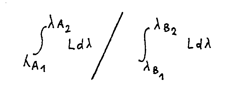
- the method which is the subject of the invention which applies to optical pyrometers with two measurement channels, of a type known per se, has its originality and finds the source of its performance in the fact that the two measurement channels, instead of working as in the known art in an almost monochromatic manner on a determined wavelength, are regulated - using filters and a dichroic mirror whose use is within the reach of the skilled person - to receive the energy transmitted by light photons in two wide optical bands, widths at least equal for example to 0.5 microns.
- the process according to the invention is sensitive, in each of its two channels, no longer to the spectral luminance (ideally corresponding to a monochromatic line) but to the energy luminance which corresponds in each band to the integral of the spectral luminance between ⁇ A1 and ⁇ A2 for channel 1 and ⁇ B1 and ⁇ B2 for channel 2.
- the photodetector of the pyrometer works on energies, that is to say on really accessible physical quantities, and no longer on monochromatic wavelengths which do not really have a real existence.
- the present invention also relates to a method for processing the signals supplied by a pyrometer with three photodetectors and a pyrometer designed for the implementation of such a method.
- This method of processing the signals supplied by an optical pyrometer is characterized in that the electromagnetic information supplied by the pyrometer is transmitted simultaneously and in parallel to three photodetectors A, B and C each specialized in a wavelength band ⁇ and in that the two channels 1 and 2 of the apparatus are constituted in three different ways by successively using the pairs of photodetectors AB, BC and AC.
- the pyrometer designed for the implementation of the above method is characterized in that it comprises three photodetectors, and, to transmit the electromagnetic information from the optical sensor to these photodetectors, an optical fiber with triple core, each of those -this supplying one of the three photodetectors.
- FIG. 9 shows the block diagram of an optical pyrometer suitable for implementing the method according to the invention.
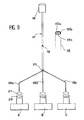
- FIG. 5 there is shown schematically a known embodiment of the photoelectric converter of an optical pyrometer with two channels 1 and 2.
- the optical information coming from the optical sensor, not shown, of the pyrometer is conveyed by optical fiber 2.
- a first lens 4 directs the beam towards a dichroic mirror 6 at 45 ° which divides it into two parts supplying channel 1 and channel 2 respectively.
- Each channel comprises a lens 8, a bandpass filter 10 , a detector 12 capable of translating the energy received by each channel into an electrical signal, then an amplifier 14 at the output of which the voltage signals V which are also referred to are available.
- the method according to the invention which uses a photoelectric converter of the same kind as that of FIG. 5, firstly comprises a calibration phase of the pyrometer thus constituted which enables it to tackle the measurement phase proper later.
- ⁇ A and ⁇ B are of the order of 0.6 to 1 ⁇ m.
- FIG. 6 shows a possible position of these two optical bandwidths ⁇ A and ⁇ B as a function of the wavelength ⁇ .
- the standard black bodies are brought to a temperature T2 and the same operations are repeated, which gives V1 (T2) and V2 (T2) as well as L A (T2) and L B (T2).
- the calibration phase is then complete and the device is ready to take a measurement.
- the thermal radiation of the body in question is examined with the pyrometer thus adjusted.
- This radiation corresponds to the electrical voltages V i and V j supplied by channel 1 and channel 2 of the pyrometer.
- the performance of an optical pyrometer implementing the process which is the subject of the invention is also remarkable as a function of the time factor, since the speed of the process being limited only by the computation time of the computer, it is possible to '' reach a temporal resolution of a few nanoseconds, in particular if one uses, moreover, detectors whose spectral sensitivity is such that it allows the processing on this time scale of relatively wide optical passbands ( ⁇ > 0.5 ⁇ m). This feature therefore allows the measurement of the temperature evolution of a body, possibly even in rapid movement, and also rapid thermal evolution.
- the optical head 16 for capturing electromagnetic radiation emitted by the body whose temperature is to be measured supplies a triple core fiber 17 at the output, a section of which has been shown on a larger scale. 18 showing the three components 19 of the fiber core. At its exit in 20, this fiber is broken down into its three hearts 19a, 19b and 19c each of which supplies one of the photodetectors A, B and C. Between the ends of the unit fibers 19 and the input of each of the detectors is mounted an accommodation lens 21 and a filter 22 defining precisely for each of the photodetectors A, B and C the wavelength domain ⁇ in which it will be required to work.
- the pyrometer of FIG. 9 is operated according to the two-channel method, object of the invention, using simultaneously the indications of the three photodetectors A, B and C grouped in three different ways according to the pairs AB, BC and AC.
- the advantage of such an arrangement is to be completely free from the possible variations in emissivity of the body to be observed between the two wavelength channels constituting each time channels 1 and 2 of the signal processing chain. and at the same time calculate the exact value of this emissivity.
- the pyrometer of FIG. 9 in association with the signal processing method, object of the invention thus makes it possible to calculate using a single pyrometric head 16, the temperature and the emissivity of a body by making only one measurement.
- One can even moreover, in the case where one effectively observes a variation in emissivity from one channel to another, determine the law of variation of this emissivity as a function of the wavelength.
Landscapes
- Physics & Mathematics (AREA)
- General Physics & Mathematics (AREA)
- Spectroscopy & Molecular Physics (AREA)
- Radiation Pyrometers (AREA)
Abstract
Description
La présente invention se rapporte au domaine des appareils de mesure de températures par voie optique, connus généralement sous le nom de pyromètres optiques. Ces appareils possèdent une tête d'observation optique des corps dont on veut mesurer la température et qui se compose essentiellement d'un capteur photoélectrique ou détecteur, apte à transformer en signal électrique - tension ou courant - le flux de photons énergétiques reçu du corps. C'est donc cette grandeur électrique dont le physicien dispose pour en déduire des renseignements sur la température du corps. L'invention concerne plus spécialement l'exploitation de ces signaux électriques. Elle concerne plus spécialement encore des pyromètres aptes à mesurer avec précision la température rapidement évolutive de corps en mouvement.The present invention relates to the field of temperature measurement devices by optical means, generally known under the name of optical pyrometers. These devices have an optical body observation head whose temperature is to be measured and which essentially consists of a photoelectric sensor or detector, capable of transforming the flow of energetic photons received from the body into an electrical signal - voltage or current. It is therefore this electrical quantity which the physicist has at his disposal to deduce therefrom information on the temperature of the body. The invention relates more specifically to the exploitation of these electrical signals. More particularly, it relates to pyrometers capable of accurately measuring the rapidly changing temperature of moving bodies.
On commencera d'abord par rappeler le principe connu du fonctionnement des pyromètres connus.We will begin by recalling the known principle of the operation of known pyrometers.
Les plus utilisés de ces appareils, parce que jusqu'à ce jour les plus précis, sont les pyromètres dits "monochromatiques" parce qu'ils travaillent sur une partie très "étroite du spectre des longueurs d'ondes, pratiquement réduite à une radiation de longueur d'onde λ. Ils s'appuient sur la propriété commune à tous les corps d'émettre un rayonnement thermique, fonction de la température et qui, pour une longueur d'onde donnée λ et pour le corps noir (corps émettant par définition toutes les radiations monochromatiques quand il est chauffé) s'exprime par la loi de Planck :

formule dans laquelle :
- L(λ,T)est la luminance spectrique du corps noir à la température absolue T et pour la longueur d'onde λ ;
- C₁ est une constante égale à 2 hc², avec h constante de Planck, et c vitesse de la lumière. C₁ a la valeur 11,9.10⁻¹⁷ W.m² ;
- C₂ est une constante égale à hc/k, avec k constante de Boltzmann. C₂ a la valeur 14.387 µm.K.
- T est la température absolue du corps.
formula in which:
- L (λ, T) is the spectral luminance of the black body at absolute temperature T and for the wavelength λ;
- C₁ is a constant equal to 2 hc², with h Planck constant, and c speed of light. C₁ has the value 11.9.10⁻¹⁷ W.m²;
- C₂ is a constant equal to hc / k, with k Boltzmann constant. C₂ has the value 14.387 µm.K.
- T is the absolute temperature of the body.
Par souci de simplification, on désignera dans la suite du présent texte, la relation de Planck précédente sous la forme :![]()
![]()
Depuis le siècle précédent, on a utilisé cette propriété des corps pour réaliser des pyromètres optiques en assimilant de façon approximative tous les corps au corps noir qui sert de référence. Si l'on observe le rayonnement d'un corps pour une longueur d'onde λ en le comparant à celui d'un corps noir de référence pour la même longueur d'onde, ceci permet, par recherche de la température T₁ telle que L (mesurée) = f(λ, T₁) de déterminer T₁. Comme la mesure directe de L par le détecteur du pyromètre n'est pas directement accessible puisque celui-ci a pour fonction de convertir les énergies en tensions électriques, on s'y prend de la façon suivante, décrite en se référant aux figures 1 et 2 ci-jointes.Since the previous century, this property of bodies has been used to make optical pyrometers by approximating all bodies to the black body which serves as a reference. If we observe the radiation of a body for a wavelength λ by comparing it to that of a reference black body for the same wavelength, this allows, by research of the temperature T₁ such that L (measured) = f (λ, T₁) to determine T₁. As the direct measurement of L by the pyrometer detector is not directly accessible since it has the function of converting energies into electrical voltages, this is done as follows, described with reference to FIGS. 1 and 2 attached.
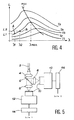
Sur la figure 1, on a représenté pour différentes températures T₁, T₂...Tn les courbes représentant la fonction L = (λ,T) pour un corps noir étalon. En chauffant par ailleurs un tel corps noir étalon aux différentes températures T₁, T₂...Tn, on note à chaque fois les tensions électriques V₁, V₂,...Vn délivrées par le détecteur du pyromètre pour une même radiation λ₁, et on les reporte sur le graphique de la figure 2 qui montre la fonction V = g(L) pour λ= λ₁. Cette fonction est linéaire et l'on a ainsi étalonné l'appareil en luminances. Lorsqu'au cours de l'observation à la longueur d'onde λ₁ d'un corps de température inconnue, le pyromètre affiche une tension V, la figure 2 permet d'en déduire la luminance L du corps observé pour la longueur d'onde λ₁.
En plaçant le point correspondant sur le graphique de la figure 1, on en déduit celle des courbes de Planck qui passe par ce point, et, par conséquent, la température.In FIG. 1, the curves representing the function L = (λ, T) for a standard black body have been represented for different temperatures T₁, T₂ ... T n . By heating in addition such a standard black body to the different temperatures T₁, T₂ ... T n , each time we note the electric voltages V₁, V₂, ... V n delivered by the detector of the pyrometer for the same radiation λ₁, and we show them on the graph of Figure 2 which shows the function V = g (L) for λ = λ₁. This function is linear and the device has therefore been calibrated in luminances. When during the observation at the wavelength λ₁ of a body of unknown temperature, the pyrometer displays a voltage V, Figure 2 allows to deduce the luminance L of the body observed for the wavelength λ₁.
By placing the corresponding point on the graph in Figure 1, we deduce that of the Planck curves which passes through this point, and, consequently, the temperature.
Une telle méthode est néanmoins très approximative car l'hypothèse faite - assimilation de tous les corps rayonnant au corps noir - est, dans certains cas, grossièrement inexacte.Such a method is nevertheless very approximate because the hypothesis made - assimilation of all the radiating bodies to the black body - is, in some cases, grossly inaccurate.
En effet, pour un corps quelconque, la loi de Planck s'écrit L =εf(λ,T), ε étant un facteur sans dimension, appelé émissivité, qui traduit l'écart entre la luminance idéale et la luminance réelle et qui dépend de certaines caractéristiques du corps émissif, comme, entre autres, la nature du corps, sa température, son état de surface, la longueur d'onde d'observation, l'angle d'incidence sous lequel on l'observe etc. Ce facteur, qui est égal à 1 pour le corps noir, varie dans la pratique, de 0 à 1. A titre d'exemple, les corps isolants ont des émissivités >0,6, les métaux <0,2 et les corps polis <0,05. On réalise par conséquent l'importance des erreurs systématiques causées par ce facteur ε en pyrométrie optique et la raison pour laquelle on a cherché à en corriger les effets néfastes en recourant à la méthode connue de la pyrométrie dite "bichromatique".Indeed, for any body, Planck's law is written L = εf (λ, T), ε being a dimensionless factor, called emissivity, which translates the difference between the ideal luminance and the real luminance and which depends certain characteristics of the emissive body, such as, among others, the nature of the body, its temperature, its surface state, the observation wavelength, the angle of incidence under which it is observed, etc. This factor, which is equal to 1 for the black body, varies in practice, from 0 to 1. For example, the insulating bodies have emissivities> 0.6, the metals <0.2 and the polished bodies <0.05. We therefore realize the importance of systematic errors caused by this factor ε in optical pyrometry and the reason why we sought to correct the harmful effects by using the known method of pyrometry called "bichromatic".
Cette méthode connue consiste à recueillir les signaux optiques d'un examen pyrométrique sur deux longueurs d'onde λ₁ et λ₂ suffisamment voisines pour que l'on puisse supposer que l'émissivité ε est la même pour ces deux radiations. On rappelera rapidement le principe ci-après en se référant aux figures 3 et 4.This known method consists in collecting the optical signals of a pyrometric examination on two wavelengths λ₁ and λ₂ sufficiently similar for that we can assume that the emissivity ε is the same for these two radiations. The principle below will be quickly recalled with reference to FIGS. 3 and 4.
A partir d'un corps noir de référence, que l'on chauffe à différentes températures, on trace les courbes d'étalonnage V = f(L) pour chacune des deux longueurs d'onde de travail λ₁ et λ₂ (figure 3) en procédant comme précédemment pour la figure 2. L'appareil est ainsi étalonné. On mesure ensuite, pour les mêmes longueurs d'onde λ₁ et λ₂ les tensions électriques V₁ et V₂ émises par le photodétecteur du pyromètre lors de l'observation d'un corps de température inconnue. A partir de V₁ et V₂ reportées sur la figure 3, on déduit les luminances correspondantes L₁ et L₂ pour chaque radiation monochromatique λ₁ et λ₂. On connaît alors deux points A(λ₁, L₁) et B(λ₂, L₂) de la courbe de Planck et il est possible à un calculateur d'identifier cette courbe de façon précise, c'est-à-dire en fin de compte la température T₃ du corps observé (figure 4).From a reference black body, which is heated to different temperatures, the calibration curves V = f (L) are plotted for each of the two working wavelengths λ₁ and λ₂ (FIG. 3) proceeding as above for FIG. 2. The device is thus calibrated. Then, for the same wavelengths λ₁ and λ₂, the electrical voltages V₁ and V₂ emitted by the photodetector of the pyrometer are measured during the observation of a body of unknown temperature. From V₁ and V₂ reported in Figure 3, we deduce the corresponding luminances L₁ and L₂ for each monochromatic radiation λ₁ and λ₂. We then know two points A (λ₁, L₁) and B (λ₂, L₂) of the Planck curve and it is possible for a computer to identify this curve precisely, that is to say ultimately the temperature T₃ of the body observed (Figure 4).
Bien qu'en progrès important par rapport à la précédente, cette méthode de mesure présente encore un certain nombre de défauts systématiques et de contraintes pour sa mise en oeuvre.Although significant progress compared to the previous one, this measurement method still presents a certain number of systematic shortcomings and constraints for its implementation.
En effet, l'hypothèse selon laquelle il existe une émissivité propre pour chaque longueur d'onde est invérifiable. Par ailleurs, la précision de la mesure est limitée par la proximité nécessaire des deux points A et B (λ₁ et λ₂ voisins par hypothèse) qui conduit à une imprécision sur l'identification de la courbe de Planck passant par ces deux points. De plus, le demandeur a pu mettre en évidence que cette méthode nécessitait que les valeurs choisies pour λ₁ et λ₂ soient toutes deux inférieures à la valeur λmax correspondant au sommet de la courbe de Planck. Or, ce sommet est a priori inconnu au moment de la mesure. Cette nécessité découle de l'obligation de respecter certaines hypothèses mathématiques, telles que produit λ.T<3000 µm.K et tensions mesurées supérieures à un seuil qui varie avec l'étalonnage. Ces conditions limitent l'utilisation du pyromètre à l'étude des matériaux fortement émissifs mais dont la température est également inférieure à un certain seuil (T<3000/λ). Les fortes émissivités sont principalement obtenues dans le cas des isolants électriques (émissivité souvent supérieure à 0,6).Indeed, the hypothesis according to which there is a specific emissivity for each wavelength is unverifiable. Furthermore, the precision of the measurement is limited by the necessary proximity of the two points A and B (λ₁ and λ₂ neighbors by hypothesis) which leads to an imprecision on the identification of the Planck curve passing through these two points. In addition, the applicant was able to demonstrate that this method required that the values chosen for λ₁ and λ₂ were both less than the λ max value corresponding to the top of the Planck curve. However, this vertex is a priori unknown at the time of the measurement. This necessity arises from the obligation to respect certain mathematical hypotheses, such as product λ.T <3000 µm.K and measured voltages above a threshold which varies with the calibration. These conditions limit the use of the pyrometer to the study of highly emissive materials but whose temperature is also below a certain threshold (T <3000 / λ). The high emissivities are mainly obtained in the case of electrical insulators (emissivity often greater than 0.6).
De plus, la condition λ₁ et λ₂ < λmax imposent un fonctionnnement du pyromètre avec de faibles luminances, c'est-à-dire dans une zone voisine du seuil de détection de l'appareil.In addition, the condition λ₁ and λ₂ <λ max impose an operation of the pyrometer with low luminances, that is to say in an area close to the detection threshold of the device.
Enfin, les mesures monochromatiques nécessitent des signaux de grande amplitude et des températures ou émissivité élevées, et elles sont lentes. La méthode de pyrométrie bichromatique est donc pratiquement inapplicable à la mesure de la température de corps en mouvement à vitesse élevée et/ou à température rapidement évolutive.Finally, monochromatic measurements require signals of large amplitude and high temperatures or emissivity, and they are slow. The bichromatic pyrometry method is therefore practically inapplicable to the measurement of the temperature of bodies in motion at high speed and / or at rapidly changing temperature.
On trouvera d'ailleurs une description détaillée de cet état de l'art en matière de pyrométrie bichromatique dans la publication "Bouriannes, Moreau, Un pyromètre rapide à plusieurs couleurs", Revue de Physique Appliquée, tome 12, page 893, Mai 1977.A detailed description of this state of the art in bichromatic pyrometry can also be found in the publication "Bouriannes, Moreau, A fast pyrometer with several colors", Revue de Physique Applégé,
La présente invention a précisément pour objet un procédé d'exploitation des signaux fournis par un pyromètre optique qui permet de s'affranchir de l'émissivité et de mesurer la température de corps en mouvement et/ou à température rapidement évolutive, en effectuant les mesures non plus sur la luminance spectrique recueillie autour de deux radiations monochromatiques voisines, mais en recourant à des mesures de luminances énergétiques.The subject of the present invention is precisely a method of exploiting the signals supplied by an optical pyrometer which makes it possible to dispense with emissivity and to measure the temperature of bodies in movement and / or at rapidly changing temperature, by carrying out the measurements. neither on the spectral luminance collected around two radiations monochromatic neighbors, but using energy luminance measurements.
Ce procédé d'exploitation des signaux fournis par un pyromètre optique à deux voies 1 et 2, se caractérise en ce que :
- on définit pour chaque voie une bande passante optique large, au moins égale à 0,5 µm, à savoir, pour la
voie 1, la partie du spectre lumineux comprise entre les longueurs d'onde
voie 2, la partie de ce même spectre lumineux comprise entre les longueurs d'onde
- on prend en compte, aussi bien pour l'étalonnage de l'appareil que pour la mesure, la luminance énergétique du spectre reçu respectivement dans la première et dans la deuxième bande optique ;
- on étalonne lesphotodétecteurs en se référant à un corps noir que l'on porte successivement à au moins deux températures connues, de la façon suivante pour chacune d'elles :
- a) on mesure les tensions électriques V₁ et V₂ fournies par chaque voie du pyromètre, qui correspondent respectivement aux luminances énergétiques LA et LB inconnues émises dans chaque bande optique du pyromètre ;
- b) on calcule théoriquement ces luminances énergetiques à l'aide d'un ordinateur qui, à partir de la formule de Planck L = f(λ) effectue les intégrales,

- c) on détermine ensuite les fonctions V = g(L) pour chacune des deux voies du pyromètre;
- puis, à l'aide du pyromètre ainsi étalonné, on effectue les mesures de la température inconnue d'un corps à examiner en mettant en oeuvre les étapes suivantes :
- d) on mesure les tensions électriques Vi et Vj fournies par la voie 1 et par
la voie 2 du pyromètre lors de l'examen optique du corps ; - e) on en déduit, par les fonctions V = g(L), les valeurs LA et LB de la luminance énergétique réellement reçue par chaque voie ;
- f) on recherche par itération à l'aide d'un ordinateur celle des courbes de Planck L = f(λ) dont le rapport des intégrales

- d) on mesure les tensions électriques Vi et Vj fournies par la voie 1 et par
- a wide optical bandwidth is defined for each channel, at least equal to 0.5 μm, namely, for
channel 1, the part of the light spectrum between the wavelengthschannel 2, the part of this same light spectrum between the wavelengths - the energy luminance of the spectrum received in the first and in the second optical band is taken into account, both for the calibration of the device and for the measurement;
- the photodetectors are calibrated by referring to a black body which is brought successively to at least two known temperatures, as follows for each of them:
- a) the electric voltages V₁ and V₂ supplied by each channel of the pyrometer are measured, which correspond respectively to the unknown energy luminances L A and L B emitted in each optical band of the pyrometer;
- b) these energetic luminances are theoretically calculated using a computer which, using Planck's formula L = f (λ) performs the integrals,
- c) the functions V = g (L) are then determined for each of the two pyrometer channels;
- then, using the pyrometer thus calibrated, measurements are made of the unknown temperature of a body to be examined by implementing the following steps:
- d) the electrical voltages V i and V j supplied by
channel 1 and bychannel 2 of the pyrometer are measured during the optical examination of the body; - e) the values L A and L B of the energy luminance actually received by each channel are deduced therefrom by the functions V = g (L);
- f) we search by iteration using a computer that of the Planck curves L = f (λ) whose ratio of integrals
- d) the electrical voltages V i and V j supplied by
Comme on le comprend de ce qui précède, le procédé objet de l'invention, qui s'applique à des pyromètres optiques à deux voies de mesure, d'un type en soi connu, a son originalité et trouve la source de ses performances dans le fait que les deux voies de mesure, au lieu de travailler comme dans l'art connu de façon quasi monochromatique sur une longueur d'onde déterminée, sont réglées - à l'aide de filtres et d'un miroir dichroïque dont l'emploi est à la portée de l'homme de métier - pour recevoir l'énergie transmise par les photons lumineux dans deux bandes optiques larges, de largeurs au moins égales par exemple à 0,5 µm. Il en résulte par conséquent que le procédé selon l'invention est sensible, dans chacune de ses deux voies, non plus à la luminance spectrique (correspondant idéalement à une raie monochromatique) mais à la luminance énergétique qui correspond dans chaque bande à l'intégrale de la luminance spectrique entre ![]()
![]()
![]()
![]()
![]()
![]()
Dans ce procédé, le photodétecteur du pyromètre travaille sur des énergies, c'est-à-dire sur des grandeurs physiques réellement accessibles, et non plus sur des longueurs d'onde monochromatiques qui n'ont pas vraiment d'existence réelle.In this process, the photodetector of the pyrometer works on energies, that is to say on really accessible physical quantities, and no longer on monochromatic wavelengths which do not really have a real existence.
De plus, le procédé décrit permet de s'affranchir de l'émissivité du corps examiné, ce qui peut s'expliquer de la manière simplifiée suivante.In addition, the method described makes it possible to dispense with the emissivity of the body examined, which can be explained in the following simplified manner.
L'étape du procédé qui consiste à rechercher la courbe de Planck L = f(λ) - que la théorie indique comme étant unique - pour laquelle le rapport des deux intégrales
est égal au rapport LA/LB déduit de la mesure, se déroule selon des séquences itératives convergentes qui comparent les luminances mesurées et les luminances calculées pour chaque voie. Il en résulte à chaque instant la nécessité d'établir des comparaisons de luminances sous forme de rapports mathématiques au cours desquels le coefficient ε de la formule de Planck s'élimine automatiquement.The process step which consists in finding the Planck curve L = f (λ) - which the theory indicates as being unique - for which the ratio of the two integrals
is equal to the ratio L A / L B deduced from the measurement, takes place according to convergent iterative sequences which compare the measured luminances and the calculated luminances for each channel. It follows at all times the need to establish comparisons of luminances in the form of mathematical ratios to during which the coefficient ε of Planck's formula is automatically eliminated.
Enfin, à condition d'employer un photodétecteur approprié, le procédé objet de l'invention permet d'étendre la technique pyrométrique, autrefois réservée aux températures élevées (>1000°C) à des températures plus basses, voisines par exemple de 250°C.Finally, provided that an appropriate photodetector is used, the process which is the subject of the invention makes it possible to extend the pyrometric technique, formerly reserved for high temperatures (> 1000 ° C.) to lower temperatures, for example close to 250 ° C. .
La présente invention a également pour objet un procédé d'exploitation des signaux fournis par un pyromètre à trois photodétecteurs et un pyromètre conçu pour la mise en oeuvre d'un tel procédé.The present invention also relates to a method for processing the signals supplied by a pyrometer with three photodetectors and a pyrometer designed for the implementation of such a method.
Ce procédé d'exploitation des signaux fournis par un pyromètre optique, se caractérise en ce que l'information électromagnétique fournie par le pyromètre est transmise simultanément et en parallèle à trois photodétecteurs A, B et C spécialisé chacun dans une bande de longueur d'onde Δλ et en ce que l'on constitue les deux voies 1 et 2 de l'appareil de trois manières différentes en utilisant successivement les couples de photodétecteurs AB, BC et AC.This method of processing the signals supplied by an optical pyrometer, is characterized in that the electromagnetic information supplied by the pyrometer is transmitted simultaneously and in parallel to three photodetectors A, B and C each specialized in a wavelength band Δλ and in that the two
Le pyromètre conçu pour la mise en oeuvre du procédé précédent se caractérise en ce qu'il comporte trois photodétecteurs, et, pour transmettre l'information électromagnétique depuis le capteur optique jusqu'à ces photodétecteurs, une fibre optique à coeur triple, chacun de ceux-ci alimentant l'un des trois photodétecteurs.The pyrometer designed for the implementation of the above method is characterized in that it comprises three photodetectors, and, to transmit the electromagnetic information from the optical sensor to these photodetectors, an optical fiber with triple core, each of those -this supplying one of the three photodetectors.
De toute façon, l'invention sera mieux comprise à la lecture qui suit de la description de plusieurs exemples d'application, description qui sera faite à titre non limitatif et en ce qui concerne la théorie du fonctionnement, en se référant aux figures 5 à 8 ci-jointes, sur lesquelles :
- la figure 5 montre le schéma connu du convertisseur photoélectrique d'un pyromètre à deux voies d'un type connu ;
- la figure 6 montre la disposition des deux bandes passantes optiques ;
- la figure 7 illustre la construction des fonctions V(L) pendant la phase d'étalonnage ;
- la figure 8 illustre la phase de mesure et la recherche par l'ordinateur de la courbe L = f(λ) correspondant à la température du corps examiné.
- FIG. 5 shows the known diagram of the photoelectric converter of a two-way pyrometer of a known type;
- Figure 6 shows the arrangement of the two optical bandwidths;
- FIG. 7 illustrates the construction of the functions V (L) during the calibration phase;
- FIG. 8 illustrates the measurement phase and the search by the computer of the curve L = f (λ) corresponding to the temperature of the body examined.
La figure 9 montre le schéma de principe d'un pyromètre optique adapté à la mise en oeuvre du procédé selon l'invention.FIG. 9 shows the block diagram of an optical pyrometer suitable for implementing the method according to the invention.
Sur la figure 5, on a représenté schématiquement une réalisation connue du convertisseur photoélectrique d'un pyromètre optique à deux voies 1 et 2. Sur cette figure 5, l'information optique en provenance du capteur optique, non représenté, du pyromètre, est véhiculée par la fibre optique 2. Une première lentille 4 dirige le faisceau vers un miroir dichroïque 6 à 45° qui le divise en deux parties alimentant respectivement la voie 1 et la voie 2. Chaque voie comprend une lentille 8, un filtre passe-bande 10, un détecteur 12 apte à traduire en signal électrique l'énergie reçue par chaque voie, puis un amplificateur 14 à la sortie duquel sont disponibles les signaux de tension V dont il est question par ailleurs.In FIG. 5, there is shown schematically a known embodiment of the photoelectric converter of an optical pyrometer with two
Le procédé selon l'invention qui met en oeuvre un convertisseur photoélectrique de même nature que celui de la figure 5, comporte d'abord une phase d'étalonnage du pyromètre ainsi constitué qui le met à même d'aborder la phase de mesure proprement dite ultérieure.The method according to the invention which uses a photoelectric converter of the same kind as that of FIG. 5, firstly comprises a calibration phase of the pyrometer thus constituted which enables it to tackle the measurement phase proper later.
La phase d'étalonnage consiste d'abord, par le choix ou le réglage du miroir 6 et des filtres 10, à fixer les quatre longueurs d'onde ![]()
![]()
![]()
![]()
![]()
![]()
![]()
![]()
Ce réglage étant effectué, on examine à l'aide du pyromètre un corps noir étalon porté à une température T₁. Sous l'influence du rayonnement de ce corps noir, les voies 1 et 2 délivrent les tensions V₁(T₁) et V₂(T₁). Ces tensions correspondent aux luminances énergétiques LA(T₁) et LB(T₁) inconnues émises par le corps noir dans les bandes optiques ΔλA et ΔλB. A l'aide d'un ordinateur, spécialement programmé à cet effet, on calcule alors ces deux luminances inconnues en effectuant les intégrales suivantes de la fonction L = f(λ) de Planck :
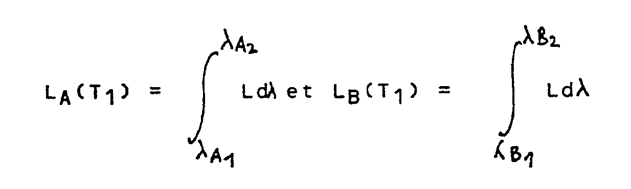
Parvenu à ce stade de l'étalonnage, on porte les corps noirs étalons à une température T₂ et l'on recommence les mêmes opérations, ce qui fournit V1(T₂) et V₂(T₂) ainsi que LA(T₂) et LB(T₂). Le but de la phase d'étalonnage étant la détermination des fonctions V = g(L) pour chaque voie, il y a à ce stade deux possibilités. Ou bien on admet, ce qui se trouve vérifié dans la majorité des cas, que ces fonctions sont linéaires et on peut alors tracer les droit-es correspondantes dans le plan (V, L) à partir des autres données précédentes, ou bien par souci de perfection, on trace complètement les deux courbes à partir d'un plus grand nombre de points en portant successivement le corps noir étalon à plusieurs températures différentes.At this stage of the calibration, the standard black bodies are brought to a temperature T₂ and the same operations are repeated, which gives V1 (T₂) and V₂ (T₂) as well as L A (T₂) and L B (T₂). The aim of the calibration phase being the determination of the functions V = g (L) for each channel, there are at this stage two possibilities. Either we admit, which is verified in the majority of cases, that these functions are linear and we can then trace the corresponding rights in the plane (V, L) from the other previous data, or for the sake of concern perfection, the two curves are completely drawn from a greater number of points by successively bringing the standard black body to several different temperatures.
La figure 7 montre la construction des deux fonctions V = g(L) dans la première hypothèse.Figure 7 shows the construction of the two functions V = g (L) in the first hypothesis.
La phase d'étalonnage est alors terminée et l'appareil est prêt à effectuer une mesure.The calibration phase is then complete and the device is ready to take a measurement.
Pour effectuer ensuite la mesure de la température d'un corps de nature et de température inconnues, on s'y prend de la façon suivante.To then measure the temperature of a body of unknown nature and temperature, it is done in the following way.
On examine avec le pyromètre ainsi réglé le rayonnement thermique du corps en question. Ce rayonnement correspond aux tensions électriques Vi et Vj fournies par la voie 1 et la voie 2 du pyromètre. En reportant ces valeurs sur les courbes d'étalonnage V = g(L) de la figure 7, on obtient les valeurs LA et LB de la luminance énergétique effectivement reçue par chacune des voies 1 et 2 de l'appareil.The thermal radiation of the body in question is examined with the pyrometer thus adjusted. This radiation corresponds to the electrical voltages V i and V j supplied by
Il suffit enfin de rechercher, par itérations successives à l'aide d'un ordinateur programmé à cet effet, dans le plan (L, λ) de la figure 8, celle des courbes de planck L = f(λ) telle que le rapport des intégrales

Ceci revient à dire que le rapport des deux surfaces S₁ et S₂ de la figure 8, délimitées par la courbe de Planck L = f(λ,T) référencée 16, et l'axe des abscisses est unique. On peut d'ailleurs rappeler que la théorie indique l'unicité de cette courbe.This amounts to saying that the ratio of the two surfaces S₁ and S₂ in Figure 8, delimited by the Planck curve L = f (λ, T) referenced 16, and the abscissa axis is unique. We can also recall that the theory indicates the uniqueness of this curve.
Comme expliqué précédemment, le résultat ainsi trouvé est indépendant de l'émissivité du corps observé et est beaucoup plus précis que celui qu'aurait fourni la méthode antérieure de la pyrométrie "bichromatique" classique.As explained above, the result thus found is independent of the emissivity of the body observed and is much more precise than that which the previous method of conventional "bichromatic" pyrometry would have provided.
Les performances d'un pyromètre optique mettant en oeuvre le procédé objet de l'invention sont également remarquables en fonction du facteur temps, car la rapidité du procédé n'étant limitée que par le temps de calcul de l'ordinateur, il est possible d'atteindre une résolution temporelle de quelques nanosecondes, notamment si l'on emploie, en outre, des détecteurs dont la sensibilité spectrale est telle qu'elle permet le traitement à cette échelle de temps de bandes passantes optiques relativement larges (Δ >0,5 µm). Cette particularité permet par conséquent la mesure de l'évolution en température d'un corps, éventuellement même en mouvement rapide, et à évolution thermique également rapide.The performance of an optical pyrometer implementing the process which is the subject of the invention is also remarkable as a function of the time factor, since the speed of the process being limited only by the computation time of the computer, it is possible to '' reach a temporal resolution of a few nanoseconds, in particular if one uses, moreover, detectors whose spectral sensitivity is such that it allows the processing on this time scale of relatively wide optical passbands (Δ> 0.5 µm). This feature therefore allows the measurement of the temperature evolution of a body, possibly even in rapid movement, and also rapid thermal evolution.
Pour rendre tout à fait claire la compréhension du mode de fonctionnement du procédé objet de l'invention, on notera qu'il est possible, si l'on ne souhaite pas disposer des températures en temps réel, d'enregistrer d'abord les valeurs des potentiels V = f(t) en fonction du temps sur chaque voie, puis de faire ensuite le calcul de recherche de l'évolution correspondante des températures.To make completely clear the understanding of the operating mode of the process which is the subject of the invention, it will be noted that it is possible, if one does not wish to have the temperatures in real time, to first record the values potentials V = f (t) as a function of time on each channel, then to do the research calculation of the corresponding evolution of temperatures.
En se référant maintenant à la figure 9, on va décrire le schéma de principe d'un pyromètre optique fonctionnant selon le procédé d'exploitation de signaux objet de l'invention et à l'aide de trois photodétecteurs montés en parallèle.Referring now to Figure 9, we will describe the block diagram of an optical pyrometer operating according to the signal processing method of the invention and using three photodetectors mounted in parallel.
Dans ce mode de réalisation d'un pyromètre optique, la tête optique 16 de captation des rayonnements électromagnétiques émis par le corps dont on veut mesurer la température alimente en sortie une fibre à coeur triple 17 dont on a représenté à plus grande échelle un tronçon en 18 montrant les trois composantes 19 du coeur de la fibre. A sa sortie en 20, cette fibre est décomposée en ses trois coeurs 19a, 19b et 19c dont chacun alimente l'un des photodétecteurs A, B et C. Entre les extrémités des fibres unitaires 19 et l'entrée de chacun des détecteurs se trouve montée une lentille d'accomodation 21 et un filtre 22 définissant précisément pour chacun des photodétecteurs A, B et C le domaine de longueur d'ondes Δλ dans lequel il sera amené à travailler. Le pyromètre de la figure 9 est exploité selon le procédé à deux voies, objet de l'invention en utilisant simultanément les indications des trois photodétecteurs A, B et C groupés de trois manières différentes selon les couples AB, BC et AC.In this embodiment of an optical pyrometer, the
L'intérêt d'un tel montage est de s'affranchir totalement des variations possibles d'émissivité du corps à observer entre les deux canaux de longueur d'ondes constituant à chaque fois les voies 1 et 2 de la chaîne d'exploitation des signaux et en même temps de calculer la valeur exacte de cette émissivité. Le pyromètre de la figure 9 en association avec le procédé d'exploitation des signaux, objet de l'invention, permet ainsi de calculer à l'aide d'une seule tête pyromètrique 16, la température et l'émissivité d'un corps en ne réalisant qu'une seule mesure. On peut même de plus, dans le cas où l'on constate effectivement une variation d'émissivité d'un canal à l'autre, déterminer la loi de variation de cette émissivité en fonction de la longueur d'onde.The advantage of such an arrangement is to be completely free from the possible variations in emissivity of the body to be observed between the two wavelength channels constituting each
Enfin, l'utilisation d'une fibre 17 à coeur triple amène un progrès très important dû au fait qu'il est très difficile sinon impossible d'utiliser un deuxième miroir dichroïque tel que le miroir 6 de la figure 5 pour réaliser, dans l'infrarouge les trois voies unitaires 19a, 19b et 19c du système. A l'aide de la fibre optique 17 au contraire, cette réalisation est d'une grande simplicité et permet d'avoir la même information électromagnétique présente au même moment sur les trois entrées des détecteurs A, B et C sans aucune complication de montage.Finally, the use of a
A titre d'exemple d'application, on a pu étudier, grâce au procédé objet de l'invention, la mesure du couple température-émissivité d'un objet en aluminium poli se déplaçant à une vitesse voisine de 2500 mètres par seconde et dont l'élévation brutale de température est provoquée par un choc intense. L'analyse spectrale, faite dans les bandes optiques comprises entre 2 µm et 4 µm, montre que la température atteint un palier au bout de 800 nanosecondes à une valeur de 445°C, l'émissivité ε atteignant la valeur 0,15.As an example of an application, it has been possible to study, using the process which is the subject of the invention, the measurement of the temperature-emissivity couple of a polished aluminum object moving at a speed close to 2500 meters per second and whose the sudden rise in temperature is caused by an intense shock. Spectral analysis, done in the optical bands between 2 µm and 4 µm, shows that the temperature reaches a plateau after 800 nanoseconds at a value of 445 ° C, the emissivity ε reaching the value 0.15.
Lorsque le pyromètre utilisant le procédé de l'invention est utilisé dans le domaine du rayonnement infrarouge, il peut fonctionner avec les performances suivantes :
- un temps de réponse inférieur de 10 nanosecondes ;
- une distance entre l'objet en mouvement et le pyromètre pouvant être supérieure à 15 mètres ;
- une surface d'analyse inférieure à 10 millimètres de côté ;
- une durée miniale d'observation de 5 microsecondes,
- une vitesse de l'objet de quelques milliers de mètres par seconde,
- une bande passante optique d'étude comprise
entre 2 et 4 micromètres (selon le choix des filtres infrarouges), - une température de luminance minimale mesurable approximative de 225 +/-25°C (selon le choix de la largeur des filtres infrarouges).
- a 10 nanosecond response time;
- a distance between the moving object and the pyrometer which may be greater than 15 meters;
- an analysis area of less than 10 millimeters per side;
- a minimum observation time of 5 microseconds,
- an object speed of a few thousand meters per second,
- an optical study bandwidth of between 2 and 4 micrometers (depending on the choice of infrared filters),
- an approximate minimum measurable luminance temperature of 225 +/- 25 ° C (depending on the choice of the width of the infrared filters).
Claims (3)


Applications Claiming Priority (2)
| Application Number | Priority Date | Filing Date | Title |
|---|---|---|---|
| FR9007790A FR2663740B1 (en) | 1990-06-21 | 1990-06-21 | PROCESS FOR EXPLOITING SIGNALS PROVIDED BY AN OPTICAL PYROMETER, PARTICULARLY FOR MEASURING ACCURATELY THE TEMPERATURE OF MOVING BODY AND AT RAPIDLY EVOLUTIVE TEMPERATURE. |
| FR9007790 | 1990-06-21 |
Publications (1)
| Publication Number | Publication Date |
|---|---|
| EP0462901A1 true EP0462901A1 (en) | 1991-12-27 |
Family
ID=9397873
Family Applications (1)
| Application Number | Title | Priority Date | Filing Date |
|---|---|---|---|
| EP91401671A Withdrawn EP0462901A1 (en) | 1990-06-21 | 1991-06-20 | Method for the use of signals by a pyrometer and pyrometer therefor |
Country Status (2)
| Country | Link |
|---|---|
| EP (1) | EP0462901A1 (en) |
| FR (1) | FR2663740B1 (en) |
Cited By (6)
| Publication number | Priority date | Publication date | Assignee | Title |
|---|---|---|---|---|
| FR2768510A1 (en) * | 1997-09-16 | 1999-03-19 | Commissariat Energie Atomique | Method and device for creating a temperature image of a very hot opaque body. |
| EP0939310A2 (en) * | 1998-02-11 | 1999-09-01 | UMM Electronics, Inc. | Blackbody lamp reference compensation algorythm using a single silicon photodiode |
| WO2005111561A1 (en) * | 2004-05-13 | 2005-11-24 | BSH Bosch und Siemens Hausgeräte GmbH | Temperature sensor for a cooking device, cooking device with electronic temperature control and method for temperature recording |
| EP1026488B1 (en) * | 1999-02-08 | 2006-10-04 | General Electric Company | Solid state optical spectrometer for combustion flame temperature measurment |
| WO2010118750A1 (en) * | 2009-04-17 | 2010-10-21 | Danfoss Ixa A/S | Gas sensor utilizing bandpass filters to measure temperature of an emitter |
| CN105738283B (en) * | 2014-12-25 | 2019-07-30 | 株式会社岛津制作所 | Optical analyzer |
Citations (2)
| Publication number | Priority date | Publication date | Assignee | Title |
|---|---|---|---|---|
| DE3149523A1 (en) * | 1981-12-14 | 1983-06-16 | VEB Meßgerätewerk "Erich Weinert" Magdeburg Betrieb des Kombinates VEB EAW Berlin-Treptow "Friedrich Ebert", 3011 Magdeburg | Method and device for contactless temperature measurement |
| DE3821476A1 (en) * | 1987-09-07 | 1989-03-16 | Weinert E Messgeraetewerk | METHOD FOR CONTACTLESS EMISSION DEGREE-INDEPENDENT TEMPERATURE MEASUREMENT ON MATERIALS WITH PROPER ABSORPTION TAPES |
-
1990
- 1990-06-21 FR FR9007790A patent/FR2663740B1/en not_active Expired - Lifetime
-
1991
- 1991-06-20 EP EP91401671A patent/EP0462901A1/en not_active Withdrawn
Patent Citations (2)
| Publication number | Priority date | Publication date | Assignee | Title |
|---|---|---|---|---|
| DE3149523A1 (en) * | 1981-12-14 | 1983-06-16 | VEB Meßgerätewerk "Erich Weinert" Magdeburg Betrieb des Kombinates VEB EAW Berlin-Treptow "Friedrich Ebert", 3011 Magdeburg | Method and device for contactless temperature measurement |
| DE3821476A1 (en) * | 1987-09-07 | 1989-03-16 | Weinert E Messgeraetewerk | METHOD FOR CONTACTLESS EMISSION DEGREE-INDEPENDENT TEMPERATURE MEASUREMENT ON MATERIALS WITH PROPER ABSORPTION TAPES |
Non-Patent Citations (1)
| Title |
|---|
| JOURNAL OF PHYSICS E/SCIENTIFIC INSTRUMENTS, vol. 20, no. 6, partie 1, juin 1987, pages 615-620, Bristol, GB; T.P. JONES et al.: "Radiation pyrometers for temperature measurement during aluminium processing" * |
Cited By (8)
| Publication number | Priority date | Publication date | Assignee | Title |
|---|---|---|---|---|
| FR2768510A1 (en) * | 1997-09-16 | 1999-03-19 | Commissariat Energie Atomique | Method and device for creating a temperature image of a very hot opaque body. |
| WO1999014566A1 (en) * | 1997-09-16 | 1999-03-25 | Commissariat A L'energie Atomique | Method and device for imaging temperatures of a very hot opaque body |
| EP0939310A2 (en) * | 1998-02-11 | 1999-09-01 | UMM Electronics, Inc. | Blackbody lamp reference compensation algorythm using a single silicon photodiode |
| EP0939310A3 (en) * | 1998-02-11 | 2000-07-05 | UMM Electronics, Inc. | Blackbody lamp reference compensation algorythm using a single silicon photodiode |
| EP1026488B1 (en) * | 1999-02-08 | 2006-10-04 | General Electric Company | Solid state optical spectrometer for combustion flame temperature measurment |
| WO2005111561A1 (en) * | 2004-05-13 | 2005-11-24 | BSH Bosch und Siemens Hausgeräte GmbH | Temperature sensor for a cooking device, cooking device with electronic temperature control and method for temperature recording |
| WO2010118750A1 (en) * | 2009-04-17 | 2010-10-21 | Danfoss Ixa A/S | Gas sensor utilizing bandpass filters to measure temperature of an emitter |
| CN105738283B (en) * | 2014-12-25 | 2019-07-30 | 株式会社岛津制作所 | Optical analyzer |
Also Published As
| Publication number | Publication date |
|---|---|
| FR2663740B1 (en) | 1992-09-11 |
| FR2663740A1 (en) | 1991-12-27 |
Similar Documents
| Publication | Publication Date | Title |
|---|---|---|
| EP0390615B1 (en) | Opto-electronic measuring device | |
| US10317281B2 (en) | Compact spectrometer | |
| JP3318397B2 (en) | Particle measurement device | |
| US20080144001A1 (en) | Spectral imaging device | |
| US6344625B1 (en) | Method and apparatus for monitoring the size variation and the focus shift of a weld pool in laser welding | |
| JP2001525938A (en) | Distributed detection system | |
| EP0558863B1 (en) | Infrared ellipsometer | |
| FR2806159A1 (en) | Optical process for non-intrusive measurement of the temperature of a flowing liquid using the fluorescence induced by a laser beam in a measured volume of liquid | |
| EP0027763B1 (en) | Process and apparatus for measuring distance by laser interferometry with two wavelengths | |
| EP1825312B1 (en) | Interferential spectroscopy detector and camera | |
| JPH04230812A (en) | Optical spectroscopy system | |
| EP0387115B1 (en) | Procedure and device to detect and measure a physical entity | |
| FR2826448A1 (en) | DIFFERENTIAL MEASUREMENT SYSTEM BASED ON THE USE OF BRAGG NETWORK PAIRS | |
| EP0262996B1 (en) | Method for the measurement of the temperature of a body by optical detection and modulated heating | |
| EP0462901A1 (en) | Method for the use of signals by a pyrometer and pyrometer therefor | |
| EP0020238A1 (en) | Method and device for the measurement of the thermal transfers of a sample, and application to the measurement of the absorption coefficient | |
| EP0971203A1 (en) | Method and apparatus for measuring the thickness of a transparent material | |
| JP3316012B2 (en) | Temperature measuring device using a micro-Raman spectrophotometer | |
| FR2572523A1 (en) | Pyrometric method and device for remote optical determination of the temperature and/or the emissivity of any body or medium | |
| EP0458752A2 (en) | Method for measuring the angle of incidence of a light beam, measuring device for carrying out the method, and distance measuring device utilising same | |
| Walton et al. | The use of area detectors in Brillouin spectroscopy | |
| FR2598218A1 (en) | CONTACTLESS LINEAR MEASURING SENSOR OF THE DISTANCE OF A TARGET BY RETROFUL RADIATION | |
| RU2366909C1 (en) | Multichannel device for measurement of pyrometric characteristics | |
| FR2497343A1 (en) | METHOD AND APPARATUS FOR MEASURING TEMPERATURE INDEPENDENTLY OF HEAT EMISSION RATE | |
| JP2758612B2 (en) | Overheat detector |
Legal Events
| Date | Code | Title | Description |
|---|---|---|---|
| PUAI | Public reference made under article 153(3) epc to a published international application that has entered the european phase |
Free format text: ORIGINAL CODE: 0009012 |
|
| AK | Designated contracting states |
Kind code of ref document: A1 Designated state(s): DE FR GB IT |
|
| 17P | Request for examination filed |
Effective date: 19920529 |
|
| 17Q | First examination report despatched |
Effective date: 19930908 |
|
| GRAG | Despatch of communication of intention to grant |
Free format text: ORIGINAL CODE: EPIDOS AGRA |
|
| GRAH | Despatch of communication of intention to grant a patent |
Free format text: ORIGINAL CODE: EPIDOS IGRA |
|
| STAA | Information on the status of an ep patent application or granted ep patent |
Free format text: STATUS: THE APPLICATION IS DEEMED TO BE WITHDRAWN |
|
| 18D | Application deemed to be withdrawn |
Effective date: 19970118 |