EP0462637B1 - Pulley arrangement for a transmission provided with a flexible transmission element - Google Patents
Pulley arrangement for a transmission provided with a flexible transmission element Download PDFInfo
- Publication number
- EP0462637B1 EP0462637B1 EP91201284A EP91201284A EP0462637B1 EP 0462637 B1 EP0462637 B1 EP 0462637B1 EP 91201284 A EP91201284 A EP 91201284A EP 91201284 A EP91201284 A EP 91201284A EP 0462637 B1 EP0462637 B1 EP 0462637B1
- Authority
- EP
- European Patent Office
- Prior art keywords
- pulley
- arrangement according
- pulley arrangement
- halves
- transmission
- Prior art date
- Legal status (The legal status is an assumption and is not a legal conclusion. Google has not performed a legal analysis and makes no representation as to the accuracy of the status listed.)
- Expired - Lifetime
Links
- 230000005540 biological transmission Effects 0.000 title claims description 15
- 239000000853 adhesive Substances 0.000 claims abstract description 7
- 230000001070 adhesive effect Effects 0.000 claims abstract description 7
- 229910000831 Steel Inorganic materials 0.000 claims abstract description 4
- 239000010959 steel Substances 0.000 claims abstract description 4
- 239000002184 metal Substances 0.000 claims description 3
- 229910052751 metal Inorganic materials 0.000 claims description 3
- 229910000975 Carbon steel Inorganic materials 0.000 claims description 2
- 229910001018 Cast iron Inorganic materials 0.000 claims description 2
- 229910001315 Tool steel Inorganic materials 0.000 claims description 2
- 239000010962 carbon steel Substances 0.000 claims description 2
- 229920002635 polyurethane Polymers 0.000 claims description 2
- 239000004814 polyurethane Substances 0.000 claims description 2
- 229910000851 Alloy steel Inorganic materials 0.000 description 2
- 239000012790 adhesive layer Substances 0.000 description 2
- 239000000463 material Substances 0.000 description 2
- 238000005266 casting Methods 0.000 description 1
- 238000010276 construction Methods 0.000 description 1
- 238000013016 damping Methods 0.000 description 1
- 230000000694 effects Effects 0.000 description 1
- 238000005242 forging Methods 0.000 description 1
- 238000004519 manufacturing process Methods 0.000 description 1
- 238000000034 method Methods 0.000 description 1
- 238000005245 sintering Methods 0.000 description 1
Images
Classifications
-
- F—MECHANICAL ENGINEERING; LIGHTING; HEATING; WEAPONS; BLASTING
- F16—ENGINEERING ELEMENTS AND UNITS; GENERAL MEASURES FOR PRODUCING AND MAINTAINING EFFECTIVE FUNCTIONING OF MACHINES OR INSTALLATIONS; THERMAL INSULATION IN GENERAL
- F16H—GEARING
- F16H55/00—Elements with teeth or friction surfaces for conveying motion; Worms, pulleys or sheaves for gearing mechanisms
- F16H55/32—Friction members
- F16H55/52—Pulleys or friction discs of adjustable construction
- F16H55/56—Pulleys or friction discs of adjustable construction of which the bearing parts are relatively axially adjustable
-
- F—MECHANICAL ENGINEERING; LIGHTING; HEATING; WEAPONS; BLASTING
- F16—ENGINEERING ELEMENTS AND UNITS; GENERAL MEASURES FOR PRODUCING AND MAINTAINING EFFECTIVE FUNCTIONING OF MACHINES OR INSTALLATIONS; THERMAL INSULATION IN GENERAL
- F16H—GEARING
- F16H55/00—Elements with teeth or friction surfaces for conveying motion; Worms, pulleys or sheaves for gearing mechanisms
- F16H55/32—Friction members
- F16H55/36—Pulleys
Definitions
- the invention relates to a pulley arrangement according to the preamble of claim 1. Such arrangements are generally known per se.
- the object of the invention is to propose a design of such a pulley arrangement which results in a considerably cheaper construction. This object is achieved by the measures described in the characterizing part of the main claim.
- reference numeral 2 indicates a shaft of a continuously variable transmission
- reference numeral 4 a pulley half made integral therewith.
- a second pulley half 6 is integral with the hub 8 and can be fitted on said shaft so that it slides in the direction of the arrows 10.
- the pulley halves are destined to co-operate with a flexible transmission element which can be a chain with hinge pins interconnected by links, or a belt comprising transverse elements fitted on a metal support.
- a flexible transmission element which can be a chain with hinge pins interconnected by links, or a belt comprising transverse elements fitted on a metal support.
- the pulley surfaces co-operating with the power-transmitting elements of the transmission element are formed by thin-walled bearing surfaces made from a high-alloy steel, for the pulley half 4 indicated by 12, and for the pulley half 6 indicated by 14.
- the two bearing surfaces are fixed to said pulley halves by means of a suitable adhesive layer, for the pulley half 4 indicated by 16, and for the pulley half 6 indicated by 18.
- a suitable adhesive is a polyurethane adhesive.
- the base material which has been found suitable for the shaft 2 with the pulley half 4 and the pulley half 6 with the hub 8 is carbon steel and cast iron respectively, while for the bearing surface a through-hardening tool steel can be used.
Landscapes
- Engineering & Computer Science (AREA)
- General Engineering & Computer Science (AREA)
- Mechanical Engineering (AREA)
- Pulleys (AREA)
- Transmissions By Endless Flexible Members (AREA)
- Gear Transmission (AREA)
- Friction Gearing (AREA)
Abstract
Description
- The invention relates to a pulley arrangement according to the preamble of claim 1. Such arrangements are generally known per se.
- In order to limit the wear caused as a result of the high stresses on such pulleys, and also in order to increase their service life, such pulleys are made of a high-grade high-alloy steel, which considerably increases the cost of a transmission provided with such pulleys. Practice has shown that, during use and under certain operating conditions the problem arises that such transmissions produce a disturbing noise depending on, inter alia, load, transmission ratio and speed of rotation, which constitutes a problem in particular if they are in the form of a continuously variable transmission for use in motor vehicles.
- The object of the invention is to propose a design of such a pulley arrangement which results in a considerably cheaper construction. This object is achieved by the measures described in the characterizing part of the main claim.
- It was surprisingly found that these measures not only reduce the cost considerably, but also considerably reduce the level of the noise caused during operation. It is felt that the explanation for this unexpected effect must be sought in the damping action of the adhesive layer present between pulley bearing surface and pulley.
- Besides, the fact that only the bearing surfaces of the pulley system need be made from a high-grade steel means that it is possible, depending on the manufacturing process for this system (forging, casting, sintering etc.) to select a material appropriate to this process which would otherwise, for cost reasons never have been considered.
- Preferred embodiments of the invention are indicated in claims 2 - 8.
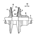
- The invention is explained with reference to the drawing. The single figure thereof shows a practical embodiment of a pulley system according to the invention.
- In the figure,
reference numeral 2 indicates a shaft of a continuously variable transmission, and reference numeral 4 a pulley half made integral therewith. Asecond pulley half 6 is integral with thehub 8 and can be fitted on said shaft so that it slides in the direction of thearrows 10. - The pulley halves are destined to co-operate with a flexible transmission element which can be a chain with hinge pins interconnected by links, or a belt comprising transverse elements fitted on a metal support.
- According to the invention, the pulley surfaces co-operating with the power-transmitting elements of the transmission element (pins, transverse elements) are formed by thin-walled bearing surfaces made from a high-alloy steel, for the
pulley half 4 indicated by 12, and for thepulley half 6 indicated by 14. The two bearing surfaces are fixed to said pulley halves by means of a suitable adhesive layer, for thepulley half 4 indicated by 16, and for thepulley half 6 indicated by 18. - A suitable adhesive is a polyurethane adhesive. The base material which has been found suitable for the
shaft 2 with thepulley half 4 and thepulley half 6 with thehub 8 is carbon steel and cast iron respectively, while for the bearing surface a through-hardening tool steel can be used.
Claims (8)
- Pulley arrangement for a variable transmission provided with a flexible transmission element, in particular a continuously variable transmission, comprising two metal pulley halves (4, 6) supported by a shaft (2), characterized in that in at least one of the pulley halves (4) the surface thereof co-operating with the transmission element is covered with a pulley bearing surface (12) made of high-grade steel and fixed thereto by means of a suitable adhesive (16).
- Pulley arrangement according to claim 1, characterized in that in both of the pulley halves (4, 6) the surface co-operating with the transmission element is covered with a pulley bearing surface (12, 14) made of high-grade steel and fixed thereto by means of a suitable adhesive (16, 18).
- Pulley arrangement according to claim 1 or 2, characterized in that the adhesive (16, 18) is a polyurethane adhesive.
- Pulley arrangement according to claims 1 - 3, characterized in that the pulley bearing surface (12, 14) is made of through-hardening tool steel.
- Pulley arrangement according to claims 1 - 4, characterized in that the pulley halves (4, 6) are made of carbon steel.
- Pulley arrangement according to claims 1 - 4, characterized in that the pulley halves (4, 6) are made of cast iron.
- Pulley arrangement according to claims 1 - 4, characterized in that the pulley halves (4, 6) are made of sintered metal.
- Pulley arrangement according to claims 1 - 7, characterized in that one of the pulley halves (4) is integral with a shaft (2) of the transmission, while the other pulley half (6) is fitted on said shaft such that it can slide in the axial direction (10).
Priority Applications (1)
| Application Number | Priority Date | Filing Date | Title |
|---|---|---|---|
| AT91201284T ATE94264T1 (en) | 1990-06-19 | 1991-05-28 | DISC FOR TRACTION GEAR. |
Applications Claiming Priority (2)
| Application Number | Priority Date | Filing Date | Title |
|---|---|---|---|
| NL9001392A NL9001392A (en) | 1990-06-19 | 1990-06-19 | PULLEY DRIVE ASSEMBLY FOR A TRANSMISSION FITTED WITH A FLEXIBLE TRANSMISSION BODY. |
| NL9001392 | 1990-06-19 |
Publications (2)
| Publication Number | Publication Date |
|---|---|
| EP0462637A1 EP0462637A1 (en) | 1991-12-27 |
| EP0462637B1 true EP0462637B1 (en) | 1993-09-08 |
Family
ID=19857276
Family Applications (1)
| Application Number | Title | Priority Date | Filing Date |
|---|---|---|---|
| EP91201284A Expired - Lifetime EP0462637B1 (en) | 1990-06-19 | 1991-05-28 | Pulley arrangement for a transmission provided with a flexible transmission element |
Country Status (5)
| Country | Link |
|---|---|
| EP (1) | EP0462637B1 (en) |
| AT (1) | ATE94264T1 (en) |
| DE (1) | DE69100344T2 (en) |
| ES (1) | ES2049082T3 (en) |
| NL (1) | NL9001392A (en) |
Cited By (1)
| Publication number | Priority date | Publication date | Assignee | Title |
|---|---|---|---|---|
| US6012998A (en) * | 1995-11-28 | 2000-01-11 | Van Doorne's Transmissie B.V. | Modular pulley for continuously variable transmission |
Families Citing this family (5)
| Publication number | Priority date | Publication date | Assignee | Title |
|---|---|---|---|---|
| DE19743675A1 (en) * | 1996-10-08 | 1998-04-09 | Luk Getriebe Systeme Gmbh | Steplessly variable power transmission |
| DE19730400C2 (en) * | 1997-07-16 | 1999-07-15 | Daimler Chrysler Ag | Conical pulley for continuously variable belt transmission |
| DE10022846B4 (en) * | 1999-05-17 | 2013-03-28 | Schaeffler Technologies AG & Co. KG | transmission |
| NL1012328C2 (en) * | 1999-06-15 | 2000-12-22 | Skf Eng & Res Centre Bv | CVT / IVT part. |
| FR2958707B1 (en) * | 2010-04-07 | 2013-11-22 | France Reducteurs | PULLEY OF SPEED DRIVE WITH BELT. |
Family Cites Families (2)
| Publication number | Priority date | Publication date | Assignee | Title |
|---|---|---|---|---|
| US2413817A (en) * | 1943-02-05 | 1947-01-07 | Dodge Mfg Corp | Sheave |
| US3142997A (en) * | 1961-11-27 | 1964-08-04 | John F Rampe | Molded plastic pulley with heat conducting metal lining |
-
1990
- 1990-06-19 NL NL9001392A patent/NL9001392A/en not_active Application Discontinuation
-
1991
- 1991-05-28 DE DE91201284T patent/DE69100344T2/en not_active Expired - Fee Related
- 1991-05-28 EP EP91201284A patent/EP0462637B1/en not_active Expired - Lifetime
- 1991-05-28 ES ES91201284T patent/ES2049082T3/en not_active Expired - Lifetime
- 1991-05-28 AT AT91201284T patent/ATE94264T1/en not_active IP Right Cessation
Cited By (1)
| Publication number | Priority date | Publication date | Assignee | Title |
|---|---|---|---|---|
| US6012998A (en) * | 1995-11-28 | 2000-01-11 | Van Doorne's Transmissie B.V. | Modular pulley for continuously variable transmission |
Also Published As
| Publication number | Publication date |
|---|---|
| NL9001392A (en) | 1992-01-16 |
| EP0462637A1 (en) | 1991-12-27 |
| DE69100344T2 (en) | 1994-05-05 |
| ES2049082T3 (en) | 1994-04-01 |
| DE69100344D1 (en) | 1993-10-14 |
| ATE94264T1 (en) | 1993-09-15 |
Similar Documents
| Publication | Publication Date | Title |
|---|---|---|
| CA1192057A (en) | Transaxle | |
| KR100348871B1 (en) | Belt for continuously variable transmission | |
| EP0125751B1 (en) | Chain-belt | |
| EP1985892B1 (en) | Belt type continuously variable transmission, power unit having the belt type continuously variable transmission, vehicle carrying belt type continuously variable transmission, and sheave for continuously variable transmission | |
| KR20000058176A (en) | Transmission unit for motor vehicles, pulley used thereby and method for making such a pulley | |
| EP0462637B1 (en) | Pulley arrangement for a transmission provided with a flexible transmission element | |
| JPH08105074A (en) | Belt type travel-gear assembly particularly for small-sized excavator | |
| EP1221564B1 (en) | Transmission belt provided with transverse elements having a displaceable contact line | |
| EP0658709B1 (en) | Pulley | |
| KR101248659B1 (en) | Continuously variable transmission | |
| EP1158211A2 (en) | Belt-type continuously variable transmission | |
| US4629340A (en) | Roller bearing assembly | |
| KR100306188B1 (en) | Continuously variable transmission | |
| US20060058143A1 (en) | Belt-driven conical-pulley transmission, method for producing it, and motor vehicle having such a transmission | |
| US20060058128A1 (en) | Belt-driven conical-pulley transmission, method for producing it, and motor vehicle having such a transmission | |
| GB2096237A (en) | Isolation of auxiliary-device drive belt from torsional vibrations of an I.C. engine | |
| US20060058126A1 (en) | Belt-driven conical-pulley transmission, method for producing it, and motor vehicle having such a transmission | |
| US20060052192A1 (en) | Belt-driven conical-pulley transmission, method for producing it, and motor vehicle having such a transmission | |
| US20060058127A1 (en) | Belt-driven conical-pulley transmission, method for producing it, and motor vehicle having such a transmission | |
| EP1190187B1 (en) | Cvt/ivt component | |
| US20250075771A1 (en) | Centrifugal pendulum absorber | |
| EP1529985B1 (en) | Method for operating a continuously variable transmission | |
| CN101006291A (en) | Belt-driven conical-pulley transmission, method for producing it, and motor vehicle having such a transmission | |
| JPH0125797Y2 (en) | ||
| WO2000077268A2 (en) | Ivt component |
Legal Events
| Date | Code | Title | Description |
|---|---|---|---|
| PUAI | Public reference made under article 153(3) epc to a published international application that has entered the european phase |
Free format text: ORIGINAL CODE: 0009012 |
|
| AK | Designated contracting states |
Kind code of ref document: A1 Designated state(s): AT BE CH DE ES FR GB IT LI NL SE |
|
| 17P | Request for examination filed |
Effective date: 19911031 |
|
| 17Q | First examination report despatched |
Effective date: 19930119 |
|
| GRAA | (expected) grant |
Free format text: ORIGINAL CODE: 0009210 |
|
| AK | Designated contracting states |
Kind code of ref document: B1 Designated state(s): AT BE CH DE ES FR GB IT LI NL SE |
|
| REF | Corresponds to: |
Ref document number: 94264 Country of ref document: AT Date of ref document: 19930915 Kind code of ref document: T |
|
| REF | Corresponds to: |
Ref document number: 69100344 Country of ref document: DE Date of ref document: 19931014 |
|
| ITF | It: translation for a ep patent filed | ||
| RAP2 | Party data changed (patent owner data changed or rights of a patent transferred) |
Owner name: VCST |
|
| REG | Reference to a national code |
Ref country code: CH Ref legal event code: PUE Owner name: VCST |
|
| ET | Fr: translation filed | ||
| NLT2 | Nl: modifications (of names), taken from the european patent patent bulletin |
Owner name: VCST TE ST.-TRUIDEN, BELGIE. |
|
| REG | Reference to a national code |
Ref country code: ES Ref legal event code: FG2A Ref document number: 2049082 Country of ref document: ES Kind code of ref document: T3 |
|
| NLS | Nl: assignments of ep-patents |
Owner name: VCST TE ST. TRUIDEN, BELGIE. |
|
| REG | Reference to a national code |
Ref country code: GB Ref legal event code: 732E |
|
| PLBE | No opposition filed within time limit |
Free format text: ORIGINAL CODE: 0009261 |
|
| STAA | Information on the status of an ep patent application or granted ep patent |
Free format text: STATUS: NO OPPOSITION FILED WITHIN TIME LIMIT |
|
| 26N | No opposition filed | ||
| EAL | Se: european patent in force in sweden |
Ref document number: 91201284.6 |
|
| REG | Reference to a national code |
Ref country code: GB Ref legal event code: IF02 |
|
| PGFP | Annual fee paid to national office [announced via postgrant information from national office to epo] |
Ref country code: ES Payment date: 20030522 Year of fee payment: 13 Ref country code: DE Payment date: 20030522 Year of fee payment: 13 Ref country code: AT Payment date: 20030522 Year of fee payment: 13 |
|
| PGFP | Annual fee paid to national office [announced via postgrant information from national office to epo] |
Ref country code: SE Payment date: 20030527 Year of fee payment: 13 Ref country code: FR Payment date: 20030527 Year of fee payment: 13 Ref country code: CH Payment date: 20030527 Year of fee payment: 13 Ref country code: BE Payment date: 20030527 Year of fee payment: 13 |
|
| PGFP | Annual fee paid to national office [announced via postgrant information from national office to epo] |
Ref country code: GB Payment date: 20030528 Year of fee payment: 13 |
|
| PGFP | Annual fee paid to national office [announced via postgrant information from national office to epo] |
Ref country code: NL Payment date: 20030530 Year of fee payment: 13 |
|
| PG25 | Lapsed in a contracting state [announced via postgrant information from national office to epo] |
Ref country code: GB Free format text: LAPSE BECAUSE OF NON-PAYMENT OF DUE FEES Effective date: 20040528 Ref country code: AT Free format text: LAPSE BECAUSE OF NON-PAYMENT OF DUE FEES Effective date: 20040528 |
|
| PG25 | Lapsed in a contracting state [announced via postgrant information from national office to epo] |
Ref country code: SE Free format text: LAPSE BECAUSE OF NON-PAYMENT OF DUE FEES Effective date: 20040529 Ref country code: ES Free format text: LAPSE BECAUSE OF NON-PAYMENT OF DUE FEES Effective date: 20040529 |
|
| PG25 | Lapsed in a contracting state [announced via postgrant information from national office to epo] |
Ref country code: LI Free format text: LAPSE BECAUSE OF NON-PAYMENT OF DUE FEES Effective date: 20040531 Ref country code: CH Free format text: LAPSE BECAUSE OF NON-PAYMENT OF DUE FEES Effective date: 20040531 Ref country code: BE Free format text: LAPSE BECAUSE OF NON-PAYMENT OF DUE FEES Effective date: 20040531 |
|
| BERE | Be: lapsed |
Owner name: *VCST Effective date: 20040531 |
|
| PG25 | Lapsed in a contracting state [announced via postgrant information from national office to epo] |
Ref country code: NL Free format text: LAPSE BECAUSE OF NON-PAYMENT OF DUE FEES Effective date: 20041201 Ref country code: DE Free format text: LAPSE BECAUSE OF NON-PAYMENT OF DUE FEES Effective date: 20041201 |
|
| EUG | Se: european patent has lapsed | ||
| REG | Reference to a national code |
Ref country code: CH Ref legal event code: PL |
|
| GBPC | Gb: european patent ceased through non-payment of renewal fee | ||
| PG25 | Lapsed in a contracting state [announced via postgrant information from national office to epo] |
Ref country code: FR Free format text: LAPSE BECAUSE OF NON-PAYMENT OF DUE FEES Effective date: 20050131 |
|
| NLV4 | Nl: lapsed or anulled due to non-payment of the annual fee |
Effective date: 20041201 |
|
| REG | Reference to a national code |
Ref country code: FR Ref legal event code: ST |
|
| PG25 | Lapsed in a contracting state [announced via postgrant information from national office to epo] |
Ref country code: IT Free format text: LAPSE BECAUSE OF NON-PAYMENT OF DUE FEES;WARNING: LAPSES OF ITALIAN PATENTS WITH EFFECTIVE DATE BEFORE 2007 MAY HAVE OCCURRED AT ANY TIME BEFORE 2007. THE CORRECT EFFECTIVE DATE MAY BE DIFFERENT FROM THE ONE RECORDED. Effective date: 20050528 |
|
| REG | Reference to a national code |
Ref country code: ES Ref legal event code: FD2A Effective date: 20040529 |