EP0462635A2 - Brake pressure control method and apparatus - Google Patents
Brake pressure control method and apparatus Download PDFInfo
- Publication number
- EP0462635A2 EP0462635A2 EP91201169A EP91201169A EP0462635A2 EP 0462635 A2 EP0462635 A2 EP 0462635A2 EP 91201169 A EP91201169 A EP 91201169A EP 91201169 A EP91201169 A EP 91201169A EP 0462635 A2 EP0462635 A2 EP 0462635A2
- Authority
- EP
- European Patent Office
- Prior art keywords
- wheel
- slip
- road surface
- condition
- measured
- Prior art date
- Legal status (The legal status is an assumption and is not a legal conclusion. Google has not performed a legal analysis and makes no representation as to the accuracy of the status listed.)
- Granted
Links
Images

Classifications
-
- B—PERFORMING OPERATIONS; TRANSPORTING
- B60—VEHICLES IN GENERAL
- B60T—VEHICLE BRAKE CONTROL SYSTEMS OR PARTS THEREOF; BRAKE CONTROL SYSTEMS OR PARTS THEREOF, IN GENERAL; ARRANGEMENT OF BRAKING ELEMENTS ON VEHICLES IN GENERAL; PORTABLE DEVICES FOR PREVENTING UNWANTED MOVEMENT OF VEHICLES; VEHICLE MODIFICATIONS TO FACILITATE COOLING OF BRAKES
- B60T8/00—Arrangements for adjusting wheel-braking force to meet varying vehicular or ground-surface conditions, e.g. limiting or varying distribution of braking force
- B60T8/17—Using electrical or electronic regulation means to control braking
- B60T8/176—Brake regulation specially adapted to prevent excessive wheel slip during vehicle deceleration, e.g. ABS
- B60T8/1764—Regulation during travel on surface with different coefficients of friction, e.g. between left and right sides, mu-split or between front and rear
-
- B—PERFORMING OPERATIONS; TRANSPORTING
- B60—VEHICLES IN GENERAL
- B60T—VEHICLE BRAKE CONTROL SYSTEMS OR PARTS THEREOF; BRAKE CONTROL SYSTEMS OR PARTS THEREOF, IN GENERAL; ARRANGEMENT OF BRAKING ELEMENTS ON VEHICLES IN GENERAL; PORTABLE DEVICES FOR PREVENTING UNWANTED MOVEMENT OF VEHICLES; VEHICLE MODIFICATIONS TO FACILITATE COOLING OF BRAKES
- B60T8/00—Arrangements for adjusting wheel-braking force to meet varying vehicular or ground-surface conditions, e.g. limiting or varying distribution of braking force
- B60T8/17—Using electrical or electronic regulation means to control braking
- B60T8/1755—Brake regulation specially adapted to control the stability of the vehicle, e.g. taking into account yaw rate or transverse acceleration in a curve
Definitions
- This invention relates to a method and apparatus for controlling the brake pressure applied to brakes of a vehicle, and in particular an anti-lock braking system having yaw control.
- a lateral force may also be generated between the wheel and the road surface.
- the available lateral force is maximum when there is no wheel slip present and decreases as wheel slip increases.
- the lateral force capability of the wheel is maximized when there is no wheel slip present.
- Increased lateral force capability at the front wheels contributes towards better steerability of the vehicle; while lateral force capability at the rear wheels contributes towards better stability.
- an antilock braking system must be able to effectively trade-off the longitudinal and lateral characteristics.
- the longitudinal and lateral forces of the wheels are also key factors when the vehicle is operating on a split-coefficient surface.
- a split-coefficient surface is often encountered during normal driving conditions, such as when the vehicle has the right hand side on a soft gravel shoulder while the left hand side is on asphalt.
- the longitudinal force on the higher coefficient (that is, asphalt) side of the vehicle will be substantially greater than the longitudinal force on the lower coefficient (that is, gravel shoulder) side of the vehicle, which causes an imbalance of forces.
- the lateral forces of the rear wheels are not great enough to counteract the force imbalance, a net yaw moment tending to rotate the vehicle about its vertical axis results. This incipient yaw condition requires the driver of the vehicle to perform corrective steering in order to maintain directional stability.
- an antilock braking system to be able to recognize and counteract an incipient yaw condition without auxiliary hardware or devices.
- the control action in response to the detected yaw condition is in the form of an open loop control.
- the lower rate of increase in the brake pressure during the apply portion of the antilock braking cycle may be appropriate for one road surface condition but may not be appropriate for all braking surfaces.
- a method and apparatus in accordance with the present invention are characterised by the features specified in the characterising portions of claims 1 and 8 respectively.
- This invention provides for an improved antilock braking system that recognizes and counteracts an incipient yaw condition without the requirement of auxiliary hardware or other devices. This results in an improvement of system cost and complexity.
- sensing and control of a yaw condition is accomplished based on the fact that if the brake pressures on two wheels on the same axle are equal, the wheel operating on the higher coefficient surface will have lower slip value than that operating on the lower coefficient surface.
- the antilock control system first responds to an incipient wheel lockup condition the brake pressures on both sides of each axle are identical. Based on the above, the differential slip at this time is representative of a yaw condition and the wheel with the lower slip value of the axle pair is identified as the high coefficient wheel. It is this wheel whose braking characteristics are controlled to control the yaw condition.
- control in response to a yaw condition is provided by closed loop control and therefore adapted to the particular surface condition.
- the monitored value of slip of the wheel on the high coefficient surface is controlled about a target slip value that is less than the critical slip value. This corrective action minimizes the longitudinal force imbalance resulting from the split coefficient surface.
- the need for yaw corrective action at the beginning of the stop is balanced against the need to provide maximum longitudinal force throughout the stop in order to optimize the braking performance. This is accomplished by an antilock braking control strategy that compromises between the competing objectives by adopting a strategy that minimizes the longitudinal force imbalance at the beginning of the stop and follows with a strategy that maximizes the longitudinal forces later in the stop.
- a smooth transition between the two strategies is provided to prevent an abrupt increase in longitudinal force imbalance and thereby reduce the demands upon the vehicle operator.
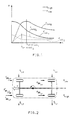
- Figure 1 An overview of the dynamic characteristics of a wheel of a vehicle are illustrated in Figure 1 which plots the force F between the wheel and road surface versus wheel slip ⁇ for a surface having a high peak coefficient of friction (solid lines) and for a surface having a low peak coefficient of friction (dashed lines). It can be seen from this graph that the lateral forces F lat1 and F lat2 between the wheel and road surface are each maximum when there is no slip and decreases as slip increases and that the longitudinal forces F long1 and F long2 increase from zero as slip increases until a peak force is reached at critical slips ⁇ critical1 and ⁇ critical2 . As can be seen, the lateral and longitudinal forces of the low coefficient surface are significantly less than the corresponding forces of the higher coefficient surface.
- these longitudinal and lateral forces act differently upon each side of the vehicle when the vehicle is braking on a split-coefficient surface. If each wheel was braked such that each wheel was operated about its respective critical slip value, the wheels on the high coefficient surface would generate more braking force than the wheels on the lower coefficient surface.
- the left side of the vehicle is operating on the higher coefficient surface ( ⁇ high ) and the right side of the vehicle is operating on the lower coefficient surface ( ⁇ low ).
- the longitudinal (braking) and lateral (cornering) forces on the various wheels are shown as F BR and F c .
- the longitudinal force on the left front wheel is labeled as F BRlf .
- the relative magnitudes of these forces are indicated by the length of the force lines.
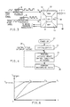
- the left side of the vehicle has greater longitudinal forces than the right side of the vehicle. This imbalance of opposite forces creates a yaw moment in the vehicle, tending to rotate it in a counterclockwise manner. If the longitudinal force imbalance remains and the rear wheel lateral forces are unable to counteract, the vehicle will rotate about its vertical axis in a counterclockwise fashion as illustrated in Figure 2 if left uncorrected by driver steering input.
- This invention recognizes the difference in slip between the wheels on the left side of the vehicle and the right side of the vehicle which accompanies such a force imbalance as being indicative of an incipient yaw condition and reduces the target slip value of the high coefficient front wheel during the beginning of the stop in order to reduce the yaw moments. This is shown as a decreased longitudinal force, F' BRlf which reduces the yaw moments.
- the invention smoothly transitions the braking strategy of the high coefficient front wheel back to a longitudinal force maximizing strategy. In doing so, braking efficiency is improved while the smooth transition minimizes the steering demands of the vehicle operator.
- the control structure of the invention takes the form of a digital computer.
- the digital computer has inputs coming from at least one conventional left wheel speed sensor via a wave shaping circuit 6 and one conventional right wheel speed sensor via a wave shaping circuit 8, and has an output to left and right wheel brake pressure modulators.
- the speed sensors and modulators are associated with the front wheels of the vehicle.
- the pressure modulators may each take the form of a motor driven piston pressure modulator such as illustrated in US Patent No. 4,881,784.
- the inputs and outputs are interfaced to the digital computer through the input/output (I/O) 10.
- the digital computer also includes a read-only memory (ROM) 12 in which the instructions necessary to execute the functions of this invention are stored, a random-access memory (RAM) 14 which is used for the storage of variables, a central processing unit (CPU) 16 which controls the operations of the digital computer, and a power supply device (PSD) 18 which interfaces the digital computer to the vehicle power system.
- ROM read-only memory
- RAM random-access memory
- CPU central processing unit
- PSD power supply device
- the instructions necessary to carry out this invention are depicted in a flow chart shown in Figure 4.
- the digital computer begins executing the instructions encoded in ROM 12.
- the first task of the digital computer upon power up is initialization ⁇ 22 ⁇ , which entails the stabilizing of voltage levels at the I/O 10, setting various RAM variables to calibrated values, ensuring the integrity of circuitry, and other basic functions of the digital computer.
- the digital computer proceeds to execute the control cycle.
- the control cycle consists of instructions which are executed once during each of successive control cycles, such as once every 5msec.
- the first general task encountered in the control cycle is the performance of antilock brake control functions as needed ⁇ 24 ⁇ .
- the antilock control functions cause wheel brake pressure to be relieved when an incipient wheel lock condition is detected as will occur when the wheel slip exceeds the critical slip value illustrated in Figure 1 and cause wheel brake pressure to be increased once the incipient lock condition is alleviated.
- the background tasks ⁇ 26 ⁇ can include such functions as: communication with off-board devices, execution of diagnostic tests, and communication with other vehicle computers, as well as any other application specific task.
- the digital computer performs the control cycle tasks once every control cycle loop. When a control cycle interrupt occurs ⁇ 28 ⁇ , the digital computer begins a new control cycle. Thus, once every control cycle, the digital computer performs antilock control functions ⁇ 24 ⁇ and executes the background tasks ⁇ 26 ⁇ .
- the antilock brake control functions ⁇ 24 ⁇ specific to this invention are detailed in Figure 5. Included in these functions but not illustrated in Figure 5 are conventional tasks such as: reading wheel speed sensor signal information and calculating wheel speeds, calculating a vehicle reference speed, calculating individual wheel slip, calculating individual wheel acceleration, and other well known functions indigenous to antilock brake control functions.
- function block ⁇ nn ⁇ generally describes the activity of the digital computer.
- the digital computer in the performance of antilock control activities, will execute functions such as: computing individual wheel speeds, computing individual wheel accelerations, calculating reference speed, and calculating individual wheel slips. All of these stated activities occur prior entering the flow chart at point A.
- the first task of the digital computer upon entering the yaw control routine at point A is to determine whether or not antilock control activities are currently active ⁇ 30 ⁇ . Antilock control is considered active when either the left or right wheel exhibits behavior such that it is likely to lock. If antilock control activities are not already active ⁇ 32 ⁇ , the next task of the digital computer is to determine the differential in slip between the left and the right side of the vehicle ⁇ 34 ⁇ . The determination of the slip differential between the left and the right sides of the vehicle ⁇ 34 ⁇ can be accomplished through a variety of methods.
- a slip difference term, ⁇ ⁇ is computed as being: where t1 corresponds to the time when the brake pedal is activated and the vehicle is braked and t2 corresponds to the time when an incipient lock condition is first detected.
- the digital computer determines whether antilock control functions are now necessary ⁇ 36 ⁇ . This can be accomplished by examining wheel slip and wheel acceleration for the left and right wheels. High wheel slip and/or high wheel deceleration can be considered indicative of an incipient lock condition. An incipient lock condition requires the antilock controller to take corrective action, meaning antilock control is now needed. Conversely, if the wheel slip and acceleration indicate that the wheel is still operating in the stable region, antilock control is not needed at this time. If antilock control for either wheel is not necessary, the digital computer simply clears the "ABS is active" flag ⁇ 38 ⁇ and exits the yaw control routine through point B.
- antilock control is now needed (block ⁇ 36 ⁇ true) the digital computer then sets the "ABS is active" flag ⁇ 40 ⁇ . It should briefly be reiterated that, in reaching this point, the following conditions were necessary: (a) antilock control was not active yet (block ⁇ 30 ⁇ false, path ⁇ 32 ⁇ ), (b) the digital computer has calculated the slip differential between the left and the right sides of the vehicle ⁇ 34 ⁇ and (c) the digital computer, after examining the critical wheel and vehicle parameters has determined the antilock control is now necessary (block ⁇ 36 ⁇ true). This means that antilock control is just now going to be initiated. It is during these first moments of antilock control in which the build-up of any yaw moments can be best counteracted thus obviating the need for corrective steering.
- the digital computer next determines whether there is a slip differential substantial enough to indicate that the vehicle may be encountering an incipient yaw condition ⁇ 42 ⁇ . If the slip differential between the left and the right sides of the vehicle computed at ⁇ 34 ⁇ is sufficiently large, this can be considered characteristic of operation on a split coefficient surface, indicating that an excessive yaw moment between the left and the right sides of the vehicle is building up. Therefore, the digital computer sets the "operating on a split coefficient surface" flag ⁇ 44 ⁇ before proceeding further. Conversely, if the slip differential represents braking on a substantially uniform surface not giving rise to excessive yaw moments, the digital computer clears the "operating on a split coefficient surface" flag ⁇ 46 ⁇ .
- K balance is a constant calibrated factor stored in ROM that accounts for the normal force imbalance and brake effectiveness imbalance between the left and right sides of the vehicle while performing straight-line and turning braking manoeuvres on a uniform coefficient surface.
- the next task of the digital computer is to determine whether or not the vehicle is likely to be operating on a split coefficient surface such that an incipient yaw condition may exist. If the "operating on a split coefficient surface" flag is clear (block ⁇ 50 ⁇ false), it is not likely that the vehicle is experiencing an incipient yaw condition, and the digital computer proceeds to perform antilock braking control as required for each of the wheels according to the respective wheel parameters ⁇ 54 ⁇ .
- a typical antilock braking cycle for a wheel performed via repeated executions of step 54 is as follows. When the wheel conditions represent an incipient wheel lockup condition such as when the wheel slip exceeds a slip threshold, a pressure release mode is indicated and brake pressure is quickly released to allow the wheel to recover from the incipient wheel lockup condition.
- wheel pressure is reapplied, such as to a significant fraction of the wheel pressure at the time pressure was released, and thereafter ramped until another incipient wheel lockup condition is sensed at which time the cycle is repeated.
- the effect of this cycling is to control the wheel slip at the slip threshold value.
- the slip threshold is a ROM stored calibration critical slip value.
- This critical slip value may, in one embodiment vary as a function of wheel acceleration or deceleration. This may be implemented in the form of a lookup table in the ROM storing the brake pressure release and apply modes as a function of wheel acceleration/deceleration and wheel slip.
- the digital computer modifies the high coefficient wheel's slip control characteristic ⁇ 52 ⁇ .
- the slip threshold of the wheel being braked on the high coefficient surface is established at a wheel slip target value ⁇ target that has an initial value less than the stored critical slip threshold to minimize the longitudinal force imbalance at the beginning of anti-lock braking. Thereafter, the wheel slip target value ⁇ target is ramped to the critical slip value whereat longitudinal braking force is maximized. The ramp provides a smooth transition between the two control strategies.
- ⁇ target (V, t, ⁇ diff )
- the initial value of ⁇ target is decreased from the critical slip value by an amount that is directly related to the slip differential ( ⁇ diff ) and the rate (the time function) at which ⁇ target approaches the critical slip value from the initial value is inversely proportional to the vehicle speed (V).
- the initial slip threshold of the high coefficient wheel is lower when the slip differential is high and closely resembles the actual critical slip value for the high coefficient wheel when the slip differential is low. This reflects the fact that, as the slip differential increases, the imbalance in longitudinal forces is likewise increasing. Thus, when there is a higher slip differential, there is a greater need for reducing the slip threshold of the wheel being braked on the higher coefficient surface to minimize the longitudinal force imbalance.
- the rate at which the slip target value ⁇ target approaches the critical slip value is dependent upon the vehicle speed when yaw control is initiated.
- the high coefficient wheel's slip threshold approaches the critical slip value at a low rate.
- the slip threshold reaches the critical slip value at a moderate-to-high rate. This reflects the concern that at high speeds, the vehicle is more sensitive to direction changes.
- Figure 6 illustrates this function whereby the slip target value, ⁇ target , representing the slip threshold of the wheel on the high coefficient surface is shown for three conditions of slip differential and vehicle speed.
- Curve f1 shows that when the slip differential is high and vehicle speed is high, (a) the initial value of the slip target value is low and (b) the slip target value approaches the critical slip value at a low rate.
- Curve f2 shows that when the slip differential is high and vehicle speed is low, (a) the initial target slip value is low and (b) approaches the critical slip value at a higher rate.
- Curve f3 shows that when the slip differential is low and vehicle speed is high, (a) the initial target slip is higher (but still below the critical slip value) and (b) approaches the critical slip value at a low rate.
- the trade-off of the longitudinal force of the high coefficient wheel between the amount needed to stop the vehicle in the minimum distance and the amount needed to minimize the longitudinal force imbalance is tailored to meet the specific requirements of the vehicle under any situation.
- the invention provides reduced longitudinal force imbalance at the beginning of the antilock action. The force imbalance then increases gradually through the stop so that the driver need only increase the steering input gradually to keep the vehicle on the desired course. Once the target slip of the front high coefficient wheel reaches the critical slip value, the braking force on the entire vehicle is maximized.
- ⁇ mod is ramped at a fixed rate to ⁇ act .
- Using the modified slip value to determine the proper release/apply mode has the same effect as shifting the slip threshold. For example, when the modified slip value exceeds the ROM stored critical slip threshold thereby indicating an incipient wheel lockup condition, the actual wheel slip is at a value lower than the critical slip threshold.
- the digital computer determines the proper command for each of the modulators and issues that command ⁇ 54 ⁇ such that the pressure at each of the controlled wheels is at or substantially near the pressure required to produce each wheel's respective slip threshold value.
- the slip threshold value will be the ROM stored critical slip value.
- the slip threshold value is ⁇ target which is varied as described above. The digital computer then proceeds to exit the yaw control routine at point B, where it completes the other tasks of the control cycle.
Abstract
Description
- This invention relates to a method and apparatus for controlling the brake pressure applied to brakes of a vehicle, and in particular an anti-lock braking system having yaw control.
- When the brakes of a vehicle are applied, a longitudinal force is generated between the wheel and the road surface. This longitudinal force is dependent upon various parameters, including the road surface conditions and the amount of slip between the wheel and the road surface. The longitudinal force increases as slip increases, until a critical slip value is surpassed. When the slip exceeds this critical slip value, the longitudinal force at the tyre-road interface decreases and the wheel rapidly approaches lockup. The longitudinal forces at the front and the rear wheels together contribute to the total braking force on the vehicle.
- As the wheel travels over the road surface, a lateral force may also be generated between the wheel and the road surface. The available lateral force is maximum when there is no wheel slip present and decreases as wheel slip increases. Thus, the lateral force capability of the wheel is maximized when there is no wheel slip present. Increased lateral force capability at the front wheels contributes towards better steerability of the vehicle; while lateral force capability at the rear wheels contributes towards better stability.
- Therefore, to obtain an optimal compromise between the objectives of lateral stability, steerability and improved stopping distance, an antilock braking system must be able to effectively trade-off the longitudinal and lateral characteristics.
- When the vehicle is braked on a uniform surface while moving in a straight line, the tyre-road friction characteristics for all four wheels are similar. In this case, the longitudinal forces on the right hand side of the vehicle and those on the left hand side are nearly equal. Consequently, the longitudinal force imbalance, if any, is small and can usually be compensated by the lateral forces at the rear wheels. Hence, little or no driver corrective steering action is required to maintain directional stability.
- The longitudinal and lateral forces of the wheels are also key factors when the vehicle is operating on a split-coefficient surface. Such a surface is often encountered during normal driving conditions, such as when the vehicle has the right hand side on a soft gravel shoulder while the left hand side is on asphalt. In such a split coefficient situation, the longitudinal force on the higher coefficient (that is, asphalt) side of the vehicle will be substantially greater than the longitudinal force on the lower coefficient (that is, gravel shoulder) side of the vehicle, which causes an imbalance of forces. If the lateral forces of the rear wheels are not great enough to counteract the force imbalance, a net yaw moment tending to rotate the vehicle about its vertical axis results. This incipient yaw condition requires the driver of the vehicle to perform corrective steering in order to maintain directional stability.
- There are known systems which attempt to detect yaw moment and take corrective action to minimize its build up when performing antilock brake manoeuvres on a split coefficient surface. These systems typically make use of devices such as lateral accelerometers, steering position sensors and other auxiliary devices to sense the yaw condition. Once sensed, a typical antilock braking system then acts to slow down the additional build-up of the yaw moment such as by commanding a lower rate of increase in brake pressure during the apply portion of an antilock braking cycle as compared to the rate of increase commanded on a uniform surface. The effect of this action is to reduce the imbalance between the longitudinal forces on the two front wheels and thereby slow down the build-up of the yaw forces.
- However, the use of auxiliary devices in these systems to sense the yaw condition tends to increase the system cost and complicate assembly and service operations. Therefore, it would be preferable for an antilock braking system to be able to recognize and counteract an incipient yaw condition without auxiliary hardware or devices. Further, the control action in response to the detected yaw condition is in the form of an open loop control. The lower rate of increase in the brake pressure during the apply portion of the antilock braking cycle may be appropriate for one road surface condition but may not be appropriate for all braking surfaces.
- Examples of the prior art can be found in US Patent Nos. 4657313; 4593955; and 4349876.
- A method and apparatus in accordance with the present invention are characterised by the features specified in the characterising portions of
claims 1 and 8 respectively. - This invention provides for an improved antilock braking system that recognizes and counteracts an incipient yaw condition without the requirement of auxiliary hardware or other devices. This results in an improvement of system cost and complexity. In accordance with one aspect of this invention, sensing and control of a yaw condition is accomplished based on the fact that if the brake pressures on two wheels on the same axle are equal, the wheel operating on the higher coefficient surface will have lower slip value than that operating on the lower coefficient surface. When the antilock control system first responds to an incipient wheel lockup condition the brake pressures on both sides of each axle are identical. Based on the above, the differential slip at this time is representative of a yaw condition and the wheel with the lower slip value of the axle pair is identified as the high coefficient wheel. It is this wheel whose braking characteristics are controlled to control the yaw condition.
- In accordance with another aspect of this invention, the control in response to a yaw condition is provided by closed loop control and therefore adapted to the particular surface condition. In one form of the invention, when an incipient yaw condition is sensed as set forth above, the monitored value of slip of the wheel on the high coefficient surface is controlled about a target slip value that is less than the critical slip value. This corrective action minimizes the longitudinal force imbalance resulting from the split coefficient surface.
- However, if the foregoing control of the high coefficient wheel about a target slip value less than the critical slip value is maintained throughout the duration of the stop, the longitudinal braking efficiency may be unnecessarily reduced. Therefore, in accordance with another aspect of this invention, the need for yaw corrective action at the beginning of the stop is balanced against the need to provide maximum longitudinal force throughout the stop in order to optimize the braking performance. This is accomplished by an antilock braking control strategy that compromises between the competing objectives by adopting a strategy that minimizes the longitudinal force imbalance at the beginning of the stop and follows with a strategy that maximizes the longitudinal forces later in the stop.
- In accordance with a further aspect of this invention a smooth transition between the two strategies is provided to prevent an abrupt increase in longitudinal force imbalance and thereby reduce the demands upon the vehicle operator.
- The present invention will now be described, by way of example, with reference to the accompanying drawings, in which:-
- Figure 1 is a plot of the lateral and longitudinal forces of a wheel operating on high and low coefficient surfaces;
- Figure 2 is a diagram illustrating the forces acting upon a vehicle;
- Figure 3 is a diagram of a digital computer of apparatus in accordance with the present invention;
- Figures 4 and 5 are flow charts illustrating the operation of the digital computer in carrying out the method of the present invention; and
- Figure 6 is a plot depicting the modification of the target slip value in response to a detected incipient yaw condition.
- An overview of the dynamic characteristics of a wheel of a vehicle are illustrated in Figure 1 which plots the force F between the wheel and road surface versus wheel slip λ for a surface having a high peak coefficient of friction (solid lines) and for a surface having a low peak coefficient of friction (dashed lines). It can be seen from this graph that the lateral forces Flat1 and Flat2 between the wheel and road surface are each maximum when there is no slip and decreases as slip increases and that the longitudinal forces Flong1 and Flong2 increase from zero as slip increases until a peak force is reached at critical slips λcritical1 and λcritical2. As can be seen, the lateral and longitudinal forces of the low coefficient surface are significantly less than the corresponding forces of the higher coefficient surface.
- As illustrated in Figure 2, these longitudinal and lateral forces act differently upon each side of the vehicle when the vehicle is braking on a split-coefficient surface. If each wheel was braked such that each wheel was operated about its respective critical slip value, the wheels on the high coefficient surface would generate more braking force than the wheels on the lower coefficient surface. In this illustration, the left side of the vehicle is operating on the higher coefficient surface (µhigh) and the right side of the vehicle is operating on the lower coefficient surface (µlow). The longitudinal (braking) and lateral (cornering) forces on the various wheels are shown as FBR and Fc. Thus, for example, the longitudinal force on the left front wheel is labeled as FBRlf. The relative magnitudes of these forces are indicated by the length of the force lines. It can be seen that the left side of the vehicle has greater longitudinal forces than the right side of the vehicle. This imbalance of opposite forces creates a yaw moment in the vehicle, tending to rotate it in a counterclockwise manner. If the longitudinal force imbalance remains and the rear wheel lateral forces are unable to counteract, the vehicle will rotate about its vertical axis in a counterclockwise fashion as illustrated in Figure 2 if left uncorrected by driver steering input.
- This invention recognizes the difference in slip between the wheels on the left side of the vehicle and the right side of the vehicle which accompanies such a force imbalance as being indicative of an incipient yaw condition and reduces the target slip value of the high coefficient front wheel during the beginning of the stop in order to reduce the yaw moments. This is shown as a decreased longitudinal force, F'BRlf which reduces the yaw moments.
- After the incipient yaw condition has been detected and the braking strategy of the high coefficient front wheel modified to be one of minimizing the longitudinal force imbalance, the invention smoothly transitions the braking strategy of the high coefficient front wheel back to a longitudinal force maximizing strategy. In doing so, braking efficiency is improved while the smooth transition minimizes the steering demands of the vehicle operator.
- In this embodiment, the control structure of the invention takes the form of a digital computer. As shown in Figure 3, the digital computer has inputs coming from at least one conventional left wheel speed sensor via a
wave shaping circuit 6 and one conventional right wheel speed sensor via awave shaping circuit 8, and has an output to left and right wheel brake pressure modulators. In this embodiment, it is assumed that the speed sensors and modulators are associated with the front wheels of the vehicle. However, it is understood that the invention is also applicable to control of the rear wheel brakes when the rear brakes are controlled individually. The pressure modulators may each take the form of a motor driven piston pressure modulator such as illustrated in US Patent No. 4,881,784. The inputs and outputs are interfaced to the digital computer through the input/output (I/O) 10. The digital computer also includes a read-only memory (ROM) 12 in which the instructions necessary to execute the functions of this invention are stored, a random-access memory (RAM) 14 which is used for the storage of variables, a central processing unit (CPU) 16 which controls the operations of the digital computer, and a power supply device (PSD) 18 which interfaces the digital computer to the vehicle power system. The digital computer is powered via the vehicle ignition or other convenient means. - The instructions necessary to carry out this invention are depicted in a flow chart shown in Figure 4. When the vehicle is powered up 〈20〉, the digital computer begins executing the instructions encoded in
ROM 12. The first task of the digital computer upon power up is initialization 〈22〉, which entails the stabilizing of voltage levels at the I/O 10, setting various RAM variables to calibrated values, ensuring the integrity of circuitry, and other basic functions of the digital computer. Once the system is initialized, the digital computer proceeds to execute the control cycle. The control cycle consists of instructions which are executed once during each of successive control cycles, such as once every 5msec. - The first general task encountered in the control cycle is the performance of antilock brake control functions as needed 〈24〉. The antilock control functions cause wheel brake pressure to be relieved when an incipient wheel lock condition is detected as will occur when the wheel slip exceeds the critical slip value illustrated in Figure 1 and cause wheel brake pressure to be increased once the incipient lock condition is alleviated. Once the digital computer performs the necessary antilock control functions, it proceeds to perform the background tasks 〈26〉. The background tasks 〈26〉 can include such functions as: communication with off-board devices, execution of diagnostic tests, and communication with other vehicle computers, as well as any other application specific task. The digital computer performs the control cycle tasks once every control cycle loop. When a control cycle interrupt occurs 〈28〉, the digital computer begins a new control cycle. Thus, once every control cycle, the digital computer performs antilock control functions 〈24〉 and executes the background tasks 〈26〉.
- The antilock brake control functions 〈24〉 specific to this invention are detailed in Figure 5. Included in these functions but not illustrated in Figure 5 are conventional tasks such as: reading wheel speed sensor signal information and calculating wheel speeds, calculating a vehicle reference speed, calculating individual wheel slip, calculating individual wheel acceleration, and other well known functions indigenous to antilock brake control functions.
- It should also be briefly noted that, in describing the functions of the digital computer, the text in function block 〈nn〉 generally describes the activity of the digital computer. Through the exercise of ordinary skill in the art, one could utilize a variety of information processing languages and/or circuit configurations to implement the task broadly described in function block 〈nn〉.
- As discussed earlier, the digital computer, in the performance of antilock control activities, will execute functions such as: computing individual wheel speeds, computing individual wheel accelerations, calculating reference speed, and calculating individual wheel slips. All of these stated activities occur prior entering the flow chart at point A.
- The first task of the digital computer upon entering the yaw control routine at point A is to determine whether or not antilock control activities are currently
active 〈 30〉. Antilock control is considered active when either the left or right wheel exhibits behavior such that it is likely to lock. If antilock control activities are not alreadyactive 〈 32〉, the next task of the digital computer is to determine the differential in slip between the left and the right side of the vehicle 〈34〉. The determination of the slip differential between the left and the right sides of the vehicle 〈34〉 can be accomplished through a variety of methods. In this embodiment, the preferred method is simply to compute the instantaneous difference in slip, λdiff, between the wheels of the axle pair on the left and the right sides of the vehicle as represented by the expression

where λl is the slip of the wheel on the left side and λr is the slip of the wheel on the right side of an axle pair. In an alternative embodiment, a slip difference term, λΔ, is computed as being: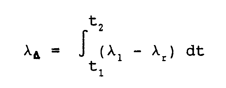
where t₁ corresponds to the time when the brake pedal is activated and the vehicle is braked and t₂ corresponds to the time when an incipient lock condition is first detected. - Next, the digital computer determines whether antilock control functions are now
necessary 〈 36〉. This can be accomplished by examining wheel slip and wheel acceleration for the left and right wheels. High wheel slip and/or high wheel deceleration can be considered indicative of an incipient lock condition. An incipient lock condition requires the antilock controller to take corrective action, meaning antilock control is now needed. Conversely, if the wheel slip and acceleration indicate that the wheel is still operating in the stable region, antilock control is not needed at this time. If antilock control for either wheel is not necessary, the digital computer simply clears the "ABS is active" flag 〈38〉 and exits the yaw control routine through point B. - If antilock control is now needed (block 〈36〉 true) the digital computer then sets the "ABS is active" flag 〈40〉. It should briefly be reiterated that, in reaching this point, the following conditions were necessary: (a) antilock control was not active yet (block 〈30〉 false, path 〈32〉), (b) the digital computer has calculated the slip differential between the left and the right sides of the vehicle 〈34〉 and (c) the digital computer, after examining the critical wheel and vehicle parameters has determined the antilock control is now necessary (block 〈36〉 true). This means that antilock control is just now going to be initiated. It is during these first moments of antilock control in which the build-up of any yaw moments can be best counteracted thus obviating the need for corrective steering.
- The digital computer next determines whether there is a slip differential substantial enough to indicate that the vehicle may be encountering an incipient yaw condition 〈42〉. If the slip differential between the left and the right sides of the vehicle computed at 〈34〉 is sufficiently large, this can be considered characteristic of operation on a split coefficient surface, indicating that an excessive yaw moment between the left and the right sides of the vehicle is building up. Therefore, the digital computer sets the "operating on a split coefficient surface" flag 〈44〉 before proceeding further. Conversely, if the slip differential represents braking on a substantially uniform surface not giving rise to excessive yaw moments, the digital computer clears the "operating on a split coefficient surface" flag 〈46〉. In practice, there is a sufficient slip differential if |λdiff| > Kbalance, where Kbalance is a constant calibrated factor stored in ROM that accounts for the normal force imbalance and brake effectiveness imbalance between the left and right sides of the vehicle while performing straight-line and turning braking manoeuvres on a uniform coefficient surface.
- The next task of the digital computer is to determine whether or not the vehicle is likely to be operating on a split coefficient surface such that an incipient yaw condition may exist. If the "operating on a split coefficient surface" flag is clear (block 〈50〉 false), it is not likely that the vehicle is experiencing an incipient yaw condition, and the digital computer proceeds to perform antilock braking control as required for each of the wheels according to the respective wheel parameters 〈54〉. A typical antilock braking cycle for a wheel performed via repeated executions of
step 54 is as follows. When the wheel conditions represent an incipient wheel lockup condition such as when the wheel slip exceeds a slip threshold, a pressure release mode is indicated and brake pressure is quickly released to allow the wheel to recover from the incipient wheel lockup condition. When wheel conditions represent a recovered condition, an apply mode is indicated and wheel pressure is reapplied, such as to a significant fraction of the wheel pressure at the time pressure was released, and thereafter ramped until another incipient wheel lockup condition is sensed at which time the cycle is repeated. The effect of this cycling is to control the wheel slip at the slip threshold value. - When the routine determines that the vehicle is being braked on a uniform road surface 〈42, 46, 50〉, the slip threshold is a ROM stored calibration critical slip value. This critical slip value may, in one embodiment vary as a function of wheel acceleration or deceleration. This may be implemented in the form of a lookup table in the ROM storing the brake pressure release and apply modes as a function of wheel acceleration/deceleration and wheel slip.
- If, however, the "operating on a split coefficient surface" flag is true (block 〈50〉 true), the digital computer modifies the high coefficient wheel's slip control
characteristic 〈 52〉. In accordance with this invention, the slip threshold of the wheel being braked on the high coefficient surface is established at a wheel slip target value λtarget that has an initial value less than the stored critical slip threshold to minimize the longitudinal force imbalance at the beginning of anti-lock braking. Thereafter, the wheel slip target value λtarget is ramped to the critical slip value whereat longitudinal braking force is maximized. The ramp provides a smooth transition between the two control strategies. - In the preferred embodiment, the modification of the high coefficient wheel's slip control characteristic at step 〈52〉 is accomplished by computing the high coefficient wheel slip target value λtarget in accordance with the general expression λtarget =(V, t, λdiff), where
 is a predetermined function of vehicle speed (V), time (t) and the measured slip differential (λdiff). Specifically, the initial value of λtarget is decreased from the critical slip value by an amount that is directly related to the slip differential (λdiff) and the rate (the time function) at which λtarget approaches the critical slip value from the initial value is inversely proportional to the vehicle speed (V). Using this form, the initial slip threshold of the high coefficient wheel is lower when the slip differential is high and closely resembles the actual critical slip value for the high coefficient wheel when the slip differential is low. This reflects the fact that, as the slip differential increases, the imbalance in longitudinal forces is likewise increasing. Thus, when there is a higher slip differential, there is a greater need for reducing the slip threshold of the wheel being braked on the higher coefficient surface to minimize the longitudinal force imbalance.
- Recall also that the rate at which the slip target value λtarget approaches the critical slip value is dependent upon the vehicle speed when yaw control is initiated. When vehicle speed is high, the high coefficient wheel's slip threshold approaches the critical slip value at a low rate. Conversely, when vehicle speed is low, the slip threshold reaches the critical slip value at a moderate-to-high rate. This reflects the concern that at high speeds, the vehicle is more sensitive to direction changes. Thus, at high vehicle speeds, it is desirable to introduce changes in the braking strategy gradually to reduce the need for driver corrective action.
- Figure 6 illustrates this function whereby the slip target value, λtarget, representing the slip threshold of the wheel on the high coefficient surface is shown for three conditions of slip differential and vehicle speed. Curve f₁ shows that when the slip differential is high and vehicle speed is high, (a) the initial value of the slip target value is low and (b) the slip target value approaches the critical slip value at a low rate. Curve f₂ shows that when the slip differential is high and vehicle speed is low, (a) the initial target slip value is low and (b) approaches the critical slip value at a higher rate. Curve f₃ shows that when the slip differential is low and vehicle speed is high, (a) the initial target slip is higher (but still below the critical slip value) and (b) approaches the critical slip value at a low rate.
- By modifying the slip threshold as a function of the initial slip differential at ABS entry and vehicle speed, the trade-off of the longitudinal force of the high coefficient wheel between the amount needed to stop the vehicle in the minimum distance and the amount needed to minimize the longitudinal force imbalance is tailored to meet the specific requirements of the vehicle under any situation. The invention provides reduced longitudinal force imbalance at the beginning of the antilock action. The force imbalance then increases gradually through the stop so that the driver need only increase the steering input gradually to keep the vehicle on the desired course. Once the target slip of the front high coefficient wheel reaches the critical slip value, the braking force on the entire vehicle is maximized.
- In a simplified version of the preferred embodiment, the modification of the high coefficient wheel's slip control characteristic is accomplished by adding a ROM stored calibrated slip offset, λoff, to the calculated wheel slip value, λact, of the high coefficient wheel to produce a modified slip value

- Once the high coefficient wheel's slip threshold has been modified 〈52〉, the digital computer determines the proper command for each of the modulators and issues that command 〈54〉 such that the pressure at each of the controlled wheels is at or substantially near the pressure required to produce each wheel's respective slip threshold value. In the case of the three wheels left unaffected by yaw control, the slip threshold value will be the ROM stored critical slip value. However, in the case of the high coefficient wheel, whose control strategy is being modified to effect yaw control, the slip threshold value is λtarget which is varied as described above. The digital computer then proceeds to exit the yaw control routine at point B, where it completes the other tasks of the control cycle.
- Once yaw control has been initiated and ABS control is still necessary, the digital computer follows path 〈30〉-〈50〉. Thus, once the yaw situation has initially been identified, yaw control remains active for all subsequent control cycles during the remainder of the ABS braking manoeuver until, through the decay of the high coefficient wheel's slip modification strategy, yaw control is no longer needed. In doing so, this invention is able to effectively trade-off the need for reduced yaw disturbance moment during the first moments of ABS braking against the need for insuring maximum longitudinal force later in the ABS stop to minimize stopping distance. Also, by effecting the movement from the one strategy to the other in a continuous fashion, the vehicle transients that can be introduced by an abrupt change in control strategies are avoided, thus reducing the demands upon the vehicle driver for corrective action.
Claims (12)
- A method for controlling brake pressure applied to respective brakes of left and right wheels of an axle of a vehicle travelling over a road surface, the method comprising the steps of measuring slip between each of the left and right wheels and the road surface; detecting an incipient lockup condition of each wheel resulting from the measured slip between that wheel and the road surface exceeding a respective slip threshold of that wheel; individually decreasing the brake pressure applied to the brake of each wheel in response to a detected incipient lockup condition of that wheel to allow wheel recovery from the incipient lockup condition; and individually increasing brake pressure to the brake of each wheel following recovery of that wheel from the incipient lockup condition, characterised by detecting a yaw condition of the vehicle resulting from the wheels being braked on respective portions of the road surface having different friction coefficients; determining the wheel being braked on the portion of the road surface having the highest friction coefficient; and, when a yaw condition is detected, decreasing the slip threshold of the wheel being braked on the portion of the road surface having the highest friction coefficient.
- A method as claimed in claim 1, wherein the step of detecting a yaw condition includes the steps of determining a difference in the measured slip between the left wheel and the road surface and the right wheel and the road surface and detecting a yaw condition of the vehicle when the determined difference in the measured slip exceeds a predetermined threshold at the time an incipient lockup condition of one of the wheels is first detected.
- A method as claimed in claim 2, wherein the difference in the measured slip is determined in accordance with the expression:

where λl and λr are the measured slips between the left and right wheels and the road surface, respectively. - A method as claimed in claim 2, further including the steps of determining a first time t₁ of a predetermined braking condition; determining a second time, t₂ when an incipient lock condition is first detected; and wherein the difference in the measured slip is determined in accordance with the expression:

- A method as claimed in claim 1, in which each respective slip threshold has an initial value; wherein the slip threshold of the wheel being braked on the portion of the road surface having the highest friction coefficient from the initial value when a yaw condition is detected is decreased, and thereafter returned to the initial value at a controlled rate.
- A method as claimed in claim 5, further including the step of determining a difference in the measured slip between the left wheel and the road surface and the right wheel and the road surface and wherein the step of decreasing the slip threshold decreases the slip threshold from the initial value by an amount that is a predetermined function of the determined difference in the measured slip at the time an incipient lockup condition of one of the wheels is first detected.
- A method as claimed in claim 5 or claim 6, further including the step of measuring vehicle speed and wherein the controlled rate is a predetermined function of the measured vehicle speed.
- Apparatus for controlling brake pressure applied to respective brakes of left and right wheels of an axle of a vehicle travelling over a road surface, the apparatus comprising, in combination, means for measuring slip between each of the left and right wheels and the road surface; means for detecting an incipient lockup condition of each wheel resulting from the measured slip between that wheel and the road surface exceeding a respective slip threshold of that wheel; means for individually decreasing the brake pressure applied to the brake of each wheel in response to a detected incipient lockup condition of that wheel to allow wheel recovery from the incipient lockup condition; and means for individually increasing brake pressure to the brake of each wheel following recovery of that wheel from the incipient lockup condition; characterised by means for detecting a yaw condition of the vehicle resulting from the wheels being braked on respective portions of the road surface having different friction coefficients; means for determining the wheel being braked on the portion of the road surface having the highest friction coefficient; and means for decreasing the slip threshold of the wheel being braked on the portion of the road surface having the highest friction coefficient, when a yaw condition is detected.
- Apparatus as claimed in claim 8, wherein the means for detecting a yaw condition includes means for determining a difference in the measured slip between the left wheel and the road surface and the right wheel and the road surface and means for detecting a yaw condition of the vehicle when the determined difference in the measured slip exceeds a predetermined threshold at the time an incipient lockup condition of one of the wheels is first detected.
- Apparatus as claimed in claim 8, in which each respective slip threshold has an initial value; wherein the means for decreasing the slip threshold of the wheel being braked on the portion of the road surface having the highest friction coefficient from the initial value when a yaw condition is detected thereafter returns the decreased slip threshold to the initial value at a controlled rate.
- Apparatus as claimed in claim 10, further including means for determining a difference in the measured slip between the left wheel and the road surface and the right wheel and the road surface and the means for decreasing the slip threshold decreases the slip threshold from the initial value by an amount that is a predetermined function of the determined difference in the measured slip at the time an incipient lockup condition of one of the wheels is first detected.
- Apparatus as claimed in claim 10 or claim 11, further including means for measuring vehicle speed and wherein the controlled rate is a predetermined function of the measured vehicle speed.
Applications Claiming Priority (2)
| Application Number | Priority Date | Filing Date | Title |
|---|---|---|---|
| US540250 | 1990-06-19 | ||
| US07/540,250 US5063514A (en) | 1990-06-19 | 1990-06-19 | Abs yaw control |
Publications (3)
| Publication Number | Publication Date |
|---|---|
| EP0462635A2 true EP0462635A2 (en) | 1991-12-27 |
| EP0462635A3 EP0462635A3 (en) | 1993-02-03 |
| EP0462635B1 EP0462635B1 (en) | 1995-08-02 |
Family
ID=24154644
Family Applications (1)
| Application Number | Title | Priority Date | Filing Date |
|---|---|---|---|
| EP91201169A Expired - Lifetime EP0462635B1 (en) | 1990-06-19 | 1991-05-15 | Brake pressure control method and apparatus |
Country Status (6)
| Country | Link |
|---|---|
| US (1) | US5063514A (en) |
| EP (1) | EP0462635B1 (en) |
| JP (1) | JP2851180B2 (en) |
| CA (1) | CA2039808C (en) |
| DE (1) | DE69111704T2 (en) |
| ES (1) | ES2075328T3 (en) |
Cited By (1)
| Publication number | Priority date | Publication date | Assignee | Title |
|---|---|---|---|---|
| WO1998003384A1 (en) * | 1996-07-18 | 1998-01-29 | Itt Manufacturing Enterprises, Inc. | Method of improving abs control behaviour |
Families Citing this family (37)
| Publication number | Priority date | Publication date | Assignee | Title |
|---|---|---|---|---|
| DE4022471A1 (en) * | 1990-07-14 | 1992-01-16 | Teves Gmbh Alfred | METHOD FOR INCREASING THE DRIVING STABILITY OF A ROAD VEHICLE |
| US5668724A (en) * | 1990-09-28 | 1997-09-16 | Robert Bosch Gmbh | Method for improving the controllabilty of motor vehicles |
| DE4031707C2 (en) * | 1990-10-06 | 2000-08-03 | Continental Teves Ag & Co Ohg | Circuit arrangement for a brake system with anti-lock or traction control |
| JPH04358955A (en) * | 1991-06-05 | 1992-12-11 | Hitachi Ltd | Safety device of antiskid control system |
| US5315518A (en) * | 1991-06-10 | 1994-05-24 | General Motors Corporation | Method and apparatus for initializing antilock brake control on split coefficient surface |
| JPH0516784A (en) * | 1991-07-12 | 1993-01-26 | Akebono Brake Ind Co Ltd | Anti-lock control method for vehicle |
| JP3207462B2 (en) * | 1991-09-13 | 2001-09-10 | マツダ株式会社 | Anti-skid brake system for vehicles |
| US5275474A (en) * | 1991-10-04 | 1994-01-04 | General Motors Corporation | Vehicle wheel slip control on split coefficient surface |
| JPH05270388A (en) * | 1992-03-27 | 1993-10-19 | Aisin Seiki Co Ltd | Device for suppressing yaw moment during braking of vehicle |
| DE4225983C2 (en) * | 1992-08-06 | 2002-03-14 | Bosch Gmbh Robert | Method for braking vehicle wheels |
| US5333942A (en) * | 1992-10-26 | 1994-08-02 | Allied-Signal Inc. | Anti-skid brake control system |
| US5416709A (en) * | 1993-11-03 | 1995-05-16 | National Science Council | Fuzzy controller for anti-skid brake systems |
| DE4418772C2 (en) * | 1994-05-28 | 2000-08-24 | Daimler Chrysler Ag | Method for regulating the brake pressure as a function of the deviation of the actual wheel slip from a target slip |
| JP3303605B2 (en) * | 1995-05-17 | 2002-07-22 | トヨタ自動車株式会社 | Vehicle behavior control device |
| US5895433A (en) * | 1996-05-23 | 1999-04-20 | General Motors Corporation | Vehicle chassis system control method and apparatus |
| US6212460B1 (en) | 1996-09-06 | 2001-04-03 | General Motors Corporation | Brake control system |
| US6325469B1 (en) | 1996-09-06 | 2001-12-04 | General Motors Corporation | Brake control system |
| US5720533A (en) * | 1996-10-15 | 1998-02-24 | General Motors Corporation | Brake control system |
| US5941919A (en) * | 1996-10-16 | 1999-08-24 | General Motors Corporation | Chassis control system |
| EP0881973B1 (en) * | 1996-12-02 | 2003-06-18 | Robert Bosch Gmbh | Process and device for adjusting the braking effect in a vehicle |
| US6547343B1 (en) | 1997-09-08 | 2003-04-15 | General Motors Corporation | Brake system control |
| US6035251A (en) * | 1997-11-10 | 2000-03-07 | General Motors Corporation | Brake system control method employing yaw rate and ship angle control |
| US6205391B1 (en) | 1998-05-18 | 2001-03-20 | General Motors Corporation | Vehicle yaw control based on yaw rate estimate |
| US6125319A (en) * | 1998-08-17 | 2000-09-26 | General Motors Corporation | Brake system control method responsive to measured vehicle acceleration |
| US6112147A (en) * | 1998-08-17 | 2000-08-29 | General Motors Corporation | Vehicle yaw rate control with bank angle compensation |
| US6079800A (en) * | 1998-08-20 | 2000-06-27 | General Motors Corporation | Active brake control with front-to-rear proportioning |
| US6169951B1 (en) * | 1998-08-21 | 2001-01-02 | General Motors Corporation | Active brake control having yaw rate estimation |
| US6175790B1 (en) | 1998-08-24 | 2001-01-16 | General Motors Corporation | Vehicle yaw rate control with yaw rate command limiting |
| US6056371A (en) * | 1998-08-24 | 2000-05-02 | General Motors Corporation | Feed-forward active brake control |
| US5931887A (en) * | 1998-09-24 | 1999-08-03 | General Motors Corporation | Brake control method based on a linear transfer function reference model |
| US6161905A (en) * | 1998-11-19 | 2000-12-19 | General Motors Corporation | Active brake control including estimation of yaw rate and slip angle |
| US6195606B1 (en) | 1998-12-07 | 2001-02-27 | General Motors Corporation | Vehicle active brake control with bank angle compensation |
| US6681167B2 (en) | 1999-12-15 | 2004-01-20 | Delphi Technologies, Inc. | Vehicle chassis control with coordinated brake and steering control on split coefficient surface |
| US6502029B2 (en) * | 2001-01-03 | 2002-12-31 | Delphi Technologies, Inc. | System and method for ABS stability control |
| US7751961B2 (en) * | 2005-09-15 | 2010-07-06 | Gm Global Technology Operations, Inc. | Acceleration/deceleration induced real-time identification of maximum tire-road friction coefficient |
| CN114056310B (en) * | 2020-08-03 | 2023-01-20 | 财团法人车辆研究测试中心 | Anti-lock brake system and control method |
| US11613237B2 (en) * | 2020-09-23 | 2023-03-28 | Automotive Research & Testing Center | Anti-lock braking system and control method thereof |
Citations (5)
| Publication number | Priority date | Publication date | Assignee | Title |
|---|---|---|---|---|
| EP0088894A2 (en) * | 1982-03-15 | 1983-09-21 | Robert Bosch Gmbh | Anti skid regulation system |
| GB2165904A (en) * | 1984-10-18 | 1986-04-23 | Teves Gmbh Alfred | Method and circuit arrangement for controlling slip when braking a road vehicle |
| EP0381957A1 (en) * | 1989-02-07 | 1990-08-16 | Knorr-Bremse Ag | Antilock braking system with limited yawing moment |
| JPH02254051A (en) * | 1989-03-27 | 1990-10-12 | Aisin Seiki Co Ltd | Antilock control device |
| DE4027356A1 (en) * | 1989-08-29 | 1991-03-14 | Tokico Ltd | Skid protection control for vehicle hydraulic braking system - reduces rate of increase in braking pressure on opposite side to braked wheel subject to skid protection |
Family Cites Families (11)
| Publication number | Priority date | Publication date | Assignee | Title |
|---|---|---|---|---|
| DE2320559C2 (en) * | 1973-04-21 | 1987-05-07 | Wabco Fahrzeugbremsen Gmbh, 3000 Hannover | Anti-lock system |
| DE2851107C2 (en) * | 1978-11-25 | 1990-03-08 | Wabco Westinghouse Fahrzeugbremsen GmbH, 3000 Hannover | Circuit arrangement for improving the driving stability of vehicles equipped with anti-lock braking systems |
| DE2855326A1 (en) * | 1978-12-21 | 1980-07-17 | Wabco Fahrzeugbremsen Gmbh | CIRCUIT ARRANGEMENT FOR IMPROVING DRIVING STABILITY IN THE BRAKE CASE OF VEHICLES WITH BLOCK-PROTECTED VEHICLE BRAKE SYSTEMS |
| US4593955A (en) * | 1983-06-14 | 1986-06-10 | Robert Bosch Gmbh | Yaw-compensated vehicle anti-skid system |
| JPS6035648A (en) * | 1983-08-09 | 1985-02-23 | Nippon Denso Co Ltd | Antiskid controller |
| DE3413738C2 (en) * | 1984-04-12 | 1993-11-04 | Teves Gmbh Alfred | SLIP CONTROL BRAKE SYSTEM FOR ROAD VEHICLES |
| JPS63500368A (en) * | 1985-06-04 | 1988-02-12 | ロ−ベルト ボツシユ ゲゼルシヤフト ミツト ベシユレンクテル ハフツング | Optimized brake slip adjustment device |
| JP2676726B2 (en) * | 1986-05-23 | 1997-11-17 | 株式会社デンソー | Anti-skid control device |
| JPS62275870A (en) * | 1986-05-26 | 1987-11-30 | Mazda Motor Corp | Vehicle skid control device |
| JP2579478B2 (en) * | 1987-04-22 | 1997-02-05 | 株式会社 曙ブレ−キ中央技術研究所 | Anti-lock manufacturing method |
| JP2641473B2 (en) * | 1988-01-30 | 1997-08-13 | マツダ株式会社 | Vehicle braking control device |
-
1990
- 1990-06-19 US US07/540,250 patent/US5063514A/en not_active Expired - Lifetime
-
1991
- 1991-04-04 CA CA002039808A patent/CA2039808C/en not_active Expired - Fee Related
- 1991-05-15 DE DE69111704T patent/DE69111704T2/en not_active Expired - Fee Related
- 1991-05-15 ES ES91201169T patent/ES2075328T3/en not_active Expired - Lifetime
- 1991-05-15 EP EP91201169A patent/EP0462635B1/en not_active Expired - Lifetime
- 1991-06-18 JP JP3146160A patent/JP2851180B2/en not_active Expired - Lifetime
Patent Citations (5)
| Publication number | Priority date | Publication date | Assignee | Title |
|---|---|---|---|---|
| EP0088894A2 (en) * | 1982-03-15 | 1983-09-21 | Robert Bosch Gmbh | Anti skid regulation system |
| GB2165904A (en) * | 1984-10-18 | 1986-04-23 | Teves Gmbh Alfred | Method and circuit arrangement for controlling slip when braking a road vehicle |
| EP0381957A1 (en) * | 1989-02-07 | 1990-08-16 | Knorr-Bremse Ag | Antilock braking system with limited yawing moment |
| JPH02254051A (en) * | 1989-03-27 | 1990-10-12 | Aisin Seiki Co Ltd | Antilock control device |
| DE4027356A1 (en) * | 1989-08-29 | 1991-03-14 | Tokico Ltd | Skid protection control for vehicle hydraulic braking system - reduces rate of increase in braking pressure on opposite side to braked wheel subject to skid protection |
Non-Patent Citations (2)
| Title |
|---|
| PATENT ABSTRACTS OF JAPAN vol. 014, no. 583 (M-1064)26 December 1990 * |
| PATENT ABSTRACTS OF JAPAN vol. 014, no. 583 (M-1064)26 December 1990& JP-A-02254051 (AISIN SEIKI CO LTD), & (US-A-5058018) * |
Cited By (2)
| Publication number | Priority date | Publication date | Assignee | Title |
|---|---|---|---|---|
| WO1998003384A1 (en) * | 1996-07-18 | 1998-01-29 | Itt Manufacturing Enterprises, Inc. | Method of improving abs control behaviour |
| US6246947B1 (en) | 1996-07-18 | 2001-06-12 | Continental Teves Ag & Co., Ohg | Method of improving ABS control behavior |
Also Published As
| Publication number | Publication date |
|---|---|
| US5063514A (en) | 1991-11-05 |
| CA2039808C (en) | 1994-09-06 |
| DE69111704T2 (en) | 1996-01-18 |
| ES2075328T3 (en) | 1995-10-01 |
| CA2039808A1 (en) | 1991-12-20 |
| JPH04252764A (en) | 1992-09-08 |
| EP0462635B1 (en) | 1995-08-02 |
| JP2851180B2 (en) | 1999-01-27 |
| EP0462635A3 (en) | 1993-02-03 |
| DE69111704D1 (en) | 1995-09-07 |
Similar Documents
| Publication | Publication Date | Title |
|---|---|---|
| EP0462635B1 (en) | Brake pressure control method and apparatus | |
| EP0958978B1 (en) | Vehicle yaw control method | |
| EP0261783B1 (en) | Adaptive mode anti-lock brake controller | |
| US8068967B2 (en) | Method of controlling an inhomogeneous roadway | |
| US8078361B2 (en) | Method and device for assisting a motor vehicle server in the vehicle stabilization | |
| US6056371A (en) | Feed-forward active brake control | |
| US6957873B2 (en) | Method for regulating the driving stability of a vehicle | |
| EP0936115B1 (en) | Brake control systems and methods | |
| US6481806B1 (en) | Vehicle braking apparatus having understeer correction with axle selection | |
| EP0219238B1 (en) | Anti-lock brake control apparatusand method | |
| KR950005660A (en) | Method and apparatus for maximizing vehicle braking and control | |
| EP0252595B1 (en) | Anti-lock brake control apparatus | |
| US6401019B2 (en) | Electric power steering apparatus | |
| EP0982206B1 (en) | Method of estimating vehicle yaw rate | |
| US5173860A (en) | Reference speed determination for an antilock brake system | |
| US7775608B2 (en) | Method for controlling a brake pressure | |
| US6466857B1 (en) | Drive wheel traction control during vehicle stability enhancement events | |
| JPH02274650A (en) | Wheel lock control system | |
| US5315518A (en) | Method and apparatus for initializing antilock brake control on split coefficient surface | |
| US5312168A (en) | Method and apparatus for equalizing vehicle brake wear | |
| US7059687B2 (en) | Braking force distribution control device | |
| EP0754608B1 (en) | Braking control system for motor vehicle | |
| US5551769A (en) | Method and system for split mu control for anti-lock brake systems | |
| JP3039071B2 (en) | Vehicle turning limit judgment device | |
| US5620240A (en) | Anti-lock brake method and system including a variable primary to secondary apply hold stage |
Legal Events
| Date | Code | Title | Description |
|---|---|---|---|
| PUAI | Public reference made under article 153(3) epc to a published international application that has entered the european phase |
Free format text: ORIGINAL CODE: 0009012 |
|
| AK | Designated contracting states |
Kind code of ref document: A2 Designated state(s): DE ES FR GB IT |
|
| PUAL | Search report despatched |
Free format text: ORIGINAL CODE: 0009013 |
|
| AK | Designated contracting states |
Kind code of ref document: A3 Designated state(s): DE ES FR GB IT |
|
| 17P | Request for examination filed |
Effective date: 19930331 |
|
| 17Q | First examination report despatched |
Effective date: 19940429 |
|
| GRAA | (expected) grant |
Free format text: ORIGINAL CODE: 0009210 |
|
| ITF | It: translation for a ep patent filed |
Owner name: BARZANO' E ZANARDO ROMA S.P.A. |
|
| AK | Designated contracting states |
Kind code of ref document: B1 Designated state(s): DE ES FR GB IT |
|
| REF | Corresponds to: |
Ref document number: 69111704 Country of ref document: DE Date of ref document: 19950907 |
|
| REG | Reference to a national code |
Ref country code: ES Ref legal event code: FG2A Ref document number: 2075328 Country of ref document: ES Kind code of ref document: T3 |
|
| ET | Fr: translation filed | ||
| PLBE | No opposition filed within time limit |
Free format text: ORIGINAL CODE: 0009261 |
|
| STAA | Information on the status of an ep patent application or granted ep patent |
Free format text: STATUS: NO OPPOSITION FILED WITHIN TIME LIMIT |
|
| 26N | No opposition filed | ||
| REG | Reference to a national code |
Ref country code: GB Ref legal event code: IF02 |
|
| REG | Reference to a national code |
Ref country code: GB Ref legal event code: 732E |
|
| PGFP | Annual fee paid to national office [announced via postgrant information from national office to epo] |
Ref country code: GB Payment date: 20050506 Year of fee payment: 15 |
|
| PGFP | Annual fee paid to national office [announced via postgrant information from national office to epo] |
Ref country code: FR Payment date: 20050516 Year of fee payment: 15 |
|
| PGFP | Annual fee paid to national office [announced via postgrant information from national office to epo] |
Ref country code: ES Payment date: 20050526 Year of fee payment: 15 |
|
| PGFP | Annual fee paid to national office [announced via postgrant information from national office to epo] |
Ref country code: DE Payment date: 20050801 Year of fee payment: 15 |
|
| PG25 | Lapsed in a contracting state [announced via postgrant information from national office to epo] |
Ref country code: GB Free format text: LAPSE BECAUSE OF NON-PAYMENT OF DUE FEES Effective date: 20060515 |
|
| PG25 | Lapsed in a contracting state [announced via postgrant information from national office to epo] |
Ref country code: ES Free format text: LAPSE BECAUSE OF NON-PAYMENT OF DUE FEES Effective date: 20060516 |
|
| PGFP | Annual fee paid to national office [announced via postgrant information from national office to epo] |
Ref country code: IT Payment date: 20060531 Year of fee payment: 16 |
|
| PG25 | Lapsed in a contracting state [announced via postgrant information from national office to epo] |
Ref country code: DE Free format text: LAPSE BECAUSE OF NON-PAYMENT OF DUE FEES Effective date: 20061201 |
|
| GBPC | Gb: european patent ceased through non-payment of renewal fee |
Effective date: 20060515 |
|
| REG | Reference to a national code |
Ref country code: FR Ref legal event code: ST Effective date: 20070131 |
|
| REG | Reference to a national code |
Ref country code: ES Ref legal event code: FD2A Effective date: 20060516 |
|
| PG25 | Lapsed in a contracting state [announced via postgrant information from national office to epo] |
Ref country code: FR Free format text: LAPSE BECAUSE OF NON-PAYMENT OF DUE FEES Effective date: 20060531 |
|
| PG25 | Lapsed in a contracting state [announced via postgrant information from national office to epo] |
Ref country code: IT Free format text: LAPSE BECAUSE OF NON-PAYMENT OF DUE FEES Effective date: 20070515 |