EP0462567A2 - Verfahren für horizontale Bohrung - Google Patents
Verfahren für horizontale Bohrung Download PDFInfo
- Publication number
- EP0462567A2 EP0462567A2 EP91109971A EP91109971A EP0462567A2 EP 0462567 A2 EP0462567 A2 EP 0462567A2 EP 91109971 A EP91109971 A EP 91109971A EP 91109971 A EP91109971 A EP 91109971A EP 0462567 A2 EP0462567 A2 EP 0462567A2
- Authority
- EP
- European Patent Office
- Prior art keywords
- well bore
- filter pack
- liner
- lateral well
- pack media
- Prior art date
- Legal status (The legal status is an assumption and is not a legal conclusion. Google has not performed a legal analysis and makes no representation as to the accuracy of the status listed.)
- Ceased
Links
- 238000005553 drilling Methods 0.000 claims abstract description 38
- 238000000034 method Methods 0.000 claims abstract description 23
- 239000012530 fluid Substances 0.000 claims description 38
- 229920001903 high density polyethylene Polymers 0.000 claims description 7
- 239000004700 high-density polyethylene Substances 0.000 claims description 7
- -1 polypropylene Polymers 0.000 claims description 7
- 238000007789 sealing Methods 0.000 claims description 7
- 239000004743 Polypropylene Substances 0.000 claims description 6
- 229920001155 polypropylene Polymers 0.000 claims description 6
- 230000002706 hydrostatic effect Effects 0.000 claims description 5
- 229920000915 polyvinyl chloride Polymers 0.000 claims description 5
- 239000004800 polyvinyl chloride Substances 0.000 claims description 5
- TZCXTZWJZNENPQ-UHFFFAOYSA-L barium sulfate Chemical compound [Ba+2].[O-]S([O-])(=O)=O TZCXTZWJZNENPQ-UHFFFAOYSA-L 0.000 claims description 4
- 229910000975 Carbon steel Inorganic materials 0.000 claims description 3
- 239000004809 Teflon Substances 0.000 claims description 3
- 229920006362 Teflon® Polymers 0.000 claims description 3
- 239000011324 bead Substances 0.000 claims description 3
- 239000000440 bentonite Substances 0.000 claims description 3
- 229910000278 bentonite Inorganic materials 0.000 claims description 3
- SVPXDRXYRYOSEX-UHFFFAOYSA-N bentoquatam Chemical compound O.O=[Si]=O.O=[Al]O[Al]=O SVPXDRXYRYOSEX-UHFFFAOYSA-N 0.000 claims description 3
- 239000010962 carbon steel Substances 0.000 claims description 3
- 239000011152 fibreglass Substances 0.000 claims description 3
- 239000011521 glass Substances 0.000 claims description 3
- 229920001684 low density polyethylene Polymers 0.000 claims description 3
- 239000004702 low-density polyethylene Substances 0.000 claims description 3
- 239000008188 pellet Substances 0.000 claims description 3
- 239000008262 pumice Substances 0.000 claims description 3
- 239000004576 sand Substances 0.000 claims description 3
- 239000010935 stainless steel Substances 0.000 claims description 3
- 229910001220 stainless steel Inorganic materials 0.000 claims description 3
- 239000004801 Chlorinated PVC Substances 0.000 claims description 2
- 229920000457 chlorinated polyvinyl chloride Polymers 0.000 claims description 2
- 238000005406 washing Methods 0.000 claims description 2
- 238000012856 packing Methods 0.000 abstract description 13
- 239000004020 conductor Substances 0.000 abstract description 4
- 238000005086 pumping Methods 0.000 abstract description 4
- 230000007613 environmental effect Effects 0.000 abstract description 3
- 238000012216 screening Methods 0.000 abstract description 2
- 239000000463 material Substances 0.000 description 8
- 238000010586 diagram Methods 0.000 description 7
- 238000005067 remediation Methods 0.000 description 7
- 238000011161 development Methods 0.000 description 6
- 230000015572 biosynthetic process Effects 0.000 description 5
- 238000005516 engineering process Methods 0.000 description 5
- 238000005755 formation reaction Methods 0.000 description 5
- 238000012544 monitoring process Methods 0.000 description 5
- 239000003673 groundwater Substances 0.000 description 4
- XLYOFNOQVPJJNP-UHFFFAOYSA-N water Substances O XLYOFNOQVPJJNP-UHFFFAOYSA-N 0.000 description 4
- 239000000356 contaminant Substances 0.000 description 3
- 239000000383 hazardous chemical Substances 0.000 description 3
- 238000002347 injection Methods 0.000 description 3
- 239000007924 injection Substances 0.000 description 3
- 238000005520 cutting process Methods 0.000 description 2
- 239000002920 hazardous waste Substances 0.000 description 2
- 239000002245 particle Substances 0.000 description 2
- 238000011084 recovery Methods 0.000 description 2
- 229920006395 saturated elastomer Polymers 0.000 description 2
- 239000003381 stabilizer Substances 0.000 description 2
- 238000003860 storage Methods 0.000 description 2
- VGGSQFUCUMXWEO-UHFFFAOYSA-N Ethene Chemical compound C=C VGGSQFUCUMXWEO-UHFFFAOYSA-N 0.000 description 1
- 230000009471 action Effects 0.000 description 1
- 239000004568 cement Substances 0.000 description 1
- 230000008859 change Effects 0.000 description 1
- 238000010276 construction Methods 0.000 description 1
- 238000011109 contamination Methods 0.000 description 1
- 238000012864 cross contamination Methods 0.000 description 1
- 230000009977 dual effect Effects 0.000 description 1
- 238000011065 in-situ storage Methods 0.000 description 1
- 230000001788 irregular Effects 0.000 description 1
- 230000007246 mechanism Effects 0.000 description 1
- 238000013508 migration Methods 0.000 description 1
- 230000005012 migration Effects 0.000 description 1
- 238000012986 modification Methods 0.000 description 1
- 230000004048 modification Effects 0.000 description 1
- 229920003023 plastic Polymers 0.000 description 1
- 239000004033 plastic Substances 0.000 description 1
- 230000009467 reduction Effects 0.000 description 1
- 239000002689 soil Substances 0.000 description 1
- 239000007787 solid Substances 0.000 description 1
- 239000007921 spray Substances 0.000 description 1
Images


Classifications
-
- E—FIXED CONSTRUCTIONS
- E21—EARTH OR ROCK DRILLING; MINING
- E21B—EARTH OR ROCK DRILLING; OBTAINING OIL, GAS, WATER, SOLUBLE OR MELTABLE MATERIALS OR A SLURRY OF MINERALS FROM WELLS
- E21B7/00—Special methods or apparatus for drilling
- E21B7/04—Directional drilling
-
- E—FIXED CONSTRUCTIONS
- E21—EARTH OR ROCK DRILLING; MINING
- E21B—EARTH OR ROCK DRILLING; OBTAINING OIL, GAS, WATER, SOLUBLE OR MELTABLE MATERIALS OR A SLURRY OF MINERALS FROM WELLS
- E21B43/00—Methods or apparatus for obtaining oil, gas, water, soluble or meltable materials or a slurry of minerals from wells
- E21B43/02—Subsoil filtering
- E21B43/04—Gravelling of wells
Definitions
- the present invention pertains to a novel horizontal well bore system which can be used to drill and develop ground water monitoring and remediation wells, and to place horizontal drains for capturing contaminant particles beneath difficult areas such as landfills, lagoons, and storage tanks.
- horizontal well bore systems have been developed and used in the past. Generally, these systems begin with a vertical hole or well. At a certain point in this vertical well, a turn of the drilling tool is initiated which eventually brings the drilling tool into a horizontal position thereby allowing the drilling of a horizontal or lateral well.
- horizontal/lateral wells have generally been used for draining large areas or as collector radials for large diameter wells.
- horizontal wells and the lateral drilling technology used to form the same have been applied in the field of pollution control. More particularly, horizontal wells can be placed beneath landfills, hazardous waste sites, or potentially or actually leaking underground storage tanks in order to monitor the migration of a hazardous substance and to prevent the hazardous substance from reaching the ground water. Horizontal wells can also be used for remediation purposes.
- U.S. Patent No. 4,832,122 to Cory, et al. discloses an in-situ remediation system for contaminated ground water which discloses the use of two horizontal wells, one positioned below the plume in the saturated zone and one above the plume in the vadose zone. A fluid is injected through the lower horizontal well into the saturated zone and, after reacting with the contaminant, is removed by the upper level extracting well for further treatment. See also, "Radial Wells and Hazardous Waste Sites", W. Dickinson, et al., RCRA SITE REMEDIATION, pp. 232-237.
- horizontal drilling systems for use with environmentally sensitive applications need to be extremely accurate, both in initial drilling accuracy and later monitoring accuracy, they need to be portable, maneuverable, and fast, and they need to drill and form a horizontal well which will maintain its integrity in a variety of corrosive and damaging environments.
- horizontal drilling systems must be cost-effective in order to meet the requirements of today's cost conscious communities and their governments.
- the present invention provides a safer, more efficient, and lower cost horizontal well drilling system, particularly for use in environmental applications, and provides a system for placing horizontal wells into a variety of areas, even areas which cannot be sampled or remediated with vertical wells. Moreover, the invention provides a system for placing a horizontal well which is drilled, cased, and screened, if desired, simultaneously in order to maintain hole integrity, speed up operations, and isolate problem zones, and for subsequently filter packing a horizontal well in order to keep sand and other objects from entering the well and/or to prevent clays or other objects from clogging the screen. The present invention also provides a horizontal well drilling system which assures quickness and accuracy under demanding and environmentally stressful conditions.
- the system of the present invention uses a slant drilling rig, a steerable drilling system equipped with a downhole hydraulic motor and a filter packing system which assures effective well development.
- the system further uses a dual drill string including a minimally reactive well casing and liner and an inner drill pipe that first pulls the casing and then the liner into place as the drilling proceeds.
- the drilling rig circulating system is a closed loop system which is self-contained and does not permit cuttings or drilling water to be spilled into the environment.
- the horizontal drilling system disclosed herein performs generally as follows.
- the slant drilling rig is rigged and a conductor casing is set. This conductor is cemented or grouted into place.
- the curved portion of the well is drilled and cased, and this casing is cemented into place.
- the horizontal section of the well is then drilled and lined, with the liner being slotted or perforated in areas where it will act as a screen. Thereafter, the liner can be filter packed and pumping equipment installed.
- the horizontal/lateral well placement is carefully engineered to meet monitoring or remediation objectives for the most efficient contaminant particle capture.
- the depth and direction of the horizontal well bore, screen length, development, and pumping methods are determined.
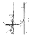
- the rig 2 may be moved onto the well site and aligned in such a way that the horizontal/lateral well 14 is drilled in the desired direction.
- the angle 4, from vertical, of the rig's mast 6 is adjusted so as to drill the lateral well 14 at the proper depth or within the target zone 16.
- An initial hole is then augered into the soil and a conductor pipe 8 is set and cemented or grouted into place.
- the curved section 10 of the well bore is started at a depth that allows the curve to reach a horizontal position at the desired location and within the target zone 16.
- the curved section 10 is drilled and cased at the same time, preferably with a minimally reactive casing, e.g., high-density polyethylene (HDPE), teflon, polypropylene, stainless steel, carbon steel, fiberglass, PVC, etc.
- a minimally reactive casing e.g., high-density polyethylene (HDPE), teflon, polypropylene, stainless steel, carbon steel, fiberglass, PVC, etc.
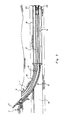
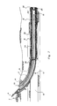
- FIG. 3 shows, on a large scale, the detailed construction of the curved section 10 which includes the curve casing 17, the lateral liner 18, and a drill pipe 19.
- the lateral liner 18 is also preferably made of minimally reactive material such as HDPE, teflon, polypropylene, stainless steel, carbon steel, fiberglass, PVC, etc.
- the steerable drilling capability for forming the curved section 10 can be provided by any generally steerable drilling motor known in the art. See, e.g., U.S. Patent Nos. 4,333,539 and 4,739,842.
- the horizontal well section can also be extended by a variety of apparatuses and methods. See, e.g., U.S. Patent Nos. 4,333,539 and 4,842,081.
- a preferred steerable system for forming both the curved and the horizontal well portions includes concentric stabilizers on a casing and the liner, both surrounding a water based drill fluid powered hydraulic motor with eccentric stabilizers thereon to tilt the motor at a slight angle to the surrounding casing or liner.
- the eccentrically mounted motor can be rotationally reoriented within the concentrically stabilized casing or liner to thereby change the motor's drilling direction and thus the direction of the well bore.
- a conventional survey instrumentation system can be used to measure the tool face orientation, azimuth and angle of inclination of a well bore drilled by the horizontal well drilling system disclosed herein.
- a preferred articulated instrument assembly for use with the present system is disclosed in U.S. Patent No. 4,901,804.
- the screen 12 which is part of the lateral liner 18 and forms a continuous pipe therewith is pulled into the lateral well bore by the drilling assembly 15.
- the screen 12 is formed by a plurality of perforations, generally indicated by the number 13, in the liner 18.
- the perforations 13 can be made in varying shapes and sizes in order to enhance the screening action and also to allow for adequate flow therethrough.
- the perforations 13 can be slits, slots, or holes.
- the perforations 13 can also be variously spaced throughout the liner 18 forming permeable and non-permeable sections of the liner 18 depending on the specific requirements of each application.
- the casing 17, liner 18, and screen 12 all include centralizers (not shown) to center the same within the bore hole and to facilitate even cementing, filter packing, and annular flow.
- the drilling assembly 15 can include a coring tool (not shown) which can be used to cut a sample from the well bore whenever one is required.
- a coring tool (not shown) which can be used to cut a sample from the well bore whenever one is required.
- One suitable coring tool is disclosed and claimed in a copending United States Patent Application identified as U.S.S.N. 07/541,836 and filed on even date herewith and incorporated for all purposes herein by this reference.
- the well itself is ready for development.
- the drill string is removed from the well leaving the screen 12 in place.
- a plug 20 is placed at the end of the screen 12 which is itself at the lower end of the horizontal well bore 14.
- the plug 20 is driven in with the drill pipe 19 and lodged at the end of the screen 12 thereby effectively sealing the end of the horizontal well bore 14.
- the screen 12 is then washed with a wash sub 22 in order to remove any drill cuttings plugging the screen slots or remaining in the well bore 14.
- the wash sub 22 contains oriented nozzles 23 which spray jets of water outwardly, thereby clearing any blockage in the screen perforations.
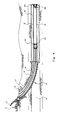
- the well bore 14 can then be filter packed if a filter in the annular volume between the well bore 14 and the screen 12 is desired.
- the wash sub 22 is pulled out of the hole and laid down.
- the filter pack fluid return line 24 is run into the hole within the liner 18 and screen 12.
- the fluid return line should be tallied in order to insure that the end of the line 24 is run into the shoe joint 26.
- the shoe or latch joint 26 is part of the plug 20 mechanism placed at the end of the screen 12.
- the filter pack fluid return line 24 can include an annular flow restrictor 28.
- the position of the flow restrictor 28 on the filter pack fluid return line 24 is initially generally such that the restrictor 28 is inside the slotted area of the screen 12 when the filter pack fluid return line 24 is in place.
- the fluid flow restrictor 28 serves to block a section of the screen 12.
- the fluid return line 24 is made of plastic of equal or near equal density to that of the fluid in the hole in order to allow the fluid return line 24 to be nearly neutrally buoyant in the well bore thereby not damaging the inner surface of the liner 18 or the screen 12 by banging, grating, etc. against it or forcing the liner 18 or screen 12 off-center by pushing against it and thereby its centralizers.
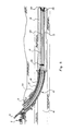
- a filter pack tremi tube 30 can be run into the casing annulus between the curve casing 17 and the lateral liner 18, also as shown in FIG. 5.
- the tremi tube 30 may not be necessary if the filter pack fluid and media can be displaced down the casing annulus itself.
- the casing annulus is then sealed and a pressure gage (not shown) is installed to monitor the same.
- the pressure within the casing annulus needs to be monitored so that excessive pressure does not, for example, fracture the formation or blow out a shallow well in a soft formation.
- excessive pressures within the casing annulus may break down the casing cement or the formation surrounding it thereby allowing unwanted contamination of the curved bore hole 10.
- the top down filter packing operation can now proceed.
- the top down filter packing procedure is started by establishing reverse circulation into the lateral hole through the casing annulus and back to the surface through the fluid return line 24.
- a pump (not shown) can be rigged up to pull a vacuum on the fluid return line 24. This will reduce the hydrostatic head and assist reverse circulation.
- An air injection line (not shown) may also be inserted into the fluid return line 24 for injecting air into the returning fluid. The air injection line could be inserted as far down as to the point where the well bore is almost horizontal, depending on how much head reduction is necessary. Air injected into the fluid return line 24 would reduce the hydrostatic head of the fluid column thereby assisting reverse circulation.
- suction pump or air injection line to reduce the hydrostatic head will depend on the hole depth and the amount of hydrostatic head to be reduced in order to allow for more uniform and less pump pressure assisted filter packing.
- Such "suction" packing would help prevent fracturing of the formation due to excessive pumping pressure.
- the filter pack media 32 is added to the circulating fluid.
- the filter pack media should preferably be a low density material such as HDPE, polypropylene, LDPE, pumice, hollow glass beads, etc.
- the filter pack media should preferably be of a matched density equal to or nearly equal to that of the circulating fluid so that the media does not tend to collect at either the upper or lower level of the lateral hole.
- the casing annulus and pump pressure gages (not shown) need to be monitored closely.
- the fluid return line 24 should be pulled so that the flow restrictor 28 is pulled back up inside the solid casing 17, as shown in FIG. 7.
- This last section of the screen 12 whose length is generally equal to that of the flow restrictor 28 and thereby known to the operator, can then be finish gravel packed with a higher density material such as PVC, CPVC, gravel, barium sulfate, sand, or other material, as needed.
- this capping material should have a density higher than that of the filter pack media already in the hole and thereby that of the circulating fluid. The use of a higher density material would form a cap over the lower density filter pack media and keep the lower density material in place.
- the filter packing procedure can be stopped when the filter pack media has been placed up to the open end of the screen 12 or even further up towards the surface.
- a large variety of different filter pack media with differing densities can be used in a variety of combinations depending on the specific needs of each application.
- the well could also be filter packed completely to the upper end of the slotted screen 12 and then held in place by the circulation of a sealing element such as bentonite pellets that would expand with time to hold the filter pack in place and effectively seal the space between the liner 18 and the casing 17.
- a sealing element such as bentonite pellets that would expand with time to hold the filter pack in place and effectively seal the space between the liner 18 and the casing 17.
- the filter packing equipment can then be rigged down, pulled and the fluid return line 24 laid down. Any additional tremi work that is needed, such as the sealing and supporting of the casing annulus with bentonite pellets, can be performed after which the tremi tube 30 can be pulled and disconnected. Additional development work can be performed at this time. For example, an electric submersible pump can be lowered into the well to complete the well development. Once the development is completed, any extra equipment needed for the ground water monitoring or remediation or for the draining of the problem site can be put into place.
Landscapes
- Life Sciences & Earth Sciences (AREA)
- Engineering & Computer Science (AREA)
- Geology (AREA)
- Mining & Mineral Resources (AREA)
- Physics & Mathematics (AREA)
- Environmental & Geological Engineering (AREA)
- Fluid Mechanics (AREA)
- General Life Sciences & Earth Sciences (AREA)
- Geochemistry & Mineralogy (AREA)
- Earth Drilling (AREA)
Applications Claiming Priority (2)
| Application Number | Priority Date | Filing Date | Title |
|---|---|---|---|
| US07/541,839 US5040601A (en) | 1990-06-21 | 1990-06-21 | Horizontal well bore system |
| US541839 | 1990-06-21 |
Publications (2)
| Publication Number | Publication Date |
|---|---|
| EP0462567A2 true EP0462567A2 (de) | 1991-12-27 |
| EP0462567A3 EP0462567A3 (en) | 1993-02-03 |
Family
ID=24161298
Family Applications (1)
| Application Number | Title | Priority Date | Filing Date |
|---|---|---|---|
| EP19910109971 Ceased EP0462567A3 (en) | 1990-06-21 | 1991-06-18 | Horizontal well bore system |
Country Status (4)
| Country | Link |
|---|---|
| US (1) | US5040601A (de) |
| EP (1) | EP0462567A3 (de) |
| AU (1) | AU645087B2 (de) |
| CA (1) | CA2043943A1 (de) |
Cited By (3)
| Publication number | Priority date | Publication date | Assignee | Title |
|---|---|---|---|---|
| WO2003040518A1 (en) * | 2001-11-08 | 2003-05-15 | Halliburton Energy Services, Inc. | Method of gravel packing a branch wellbore |
| US6994165B2 (en) | 2001-08-06 | 2006-02-07 | Halliburton Energy Services, Inc. | Multilateral open hole gravel pack completion methods |
| CN111905906A (zh) * | 2020-07-29 | 2020-11-10 | 中国石油化工股份有限公司 | 离心分离与机械破碎式煤屑清理系统及其工作方法 |
Families Citing this family (56)
| Publication number | Priority date | Publication date | Assignee | Title |
|---|---|---|---|---|
| US5253708A (en) * | 1991-12-11 | 1993-10-19 | Mobil Oil Corporation | Process and apparatus for performing gravel-packed liner completions in unconsolidated formations |
| US5255741A (en) * | 1991-12-11 | 1993-10-26 | Mobil Oil Corporation | Process and apparatus for completing a well in an unconsolidated formation |
| US5289888A (en) * | 1992-05-26 | 1994-03-01 | Rrkt Company | Water well completion method |
| US5330003A (en) * | 1992-12-22 | 1994-07-19 | Bullick Robert L | Gravel packing system with diversion of fluid |
| DE4313221C2 (de) * | 1993-04-22 | 1995-08-17 | Flowtex Service Ges Fuer Horiz | Verfahren zum Verlegen von unterirdischen Sammelleitungen für Flüssigkeiten und Gase, insbesondere zum Bau von Horizontalfilterbrunnen und Drainageleitungen, und Arbeitsmittel zur Durchführung des Verfahrens |
| US5715891A (en) * | 1995-09-27 | 1998-02-10 | Natural Reserves Group, Inc. | Method for isolating multi-lateral well completions while maintaining selective drainhole re-entry access |
| US5697445A (en) * | 1995-09-27 | 1997-12-16 | Natural Reserves Group, Inc. | Method and apparatus for selective horizontal well re-entry using retrievable diverter oriented by logging means |
| US5598890A (en) * | 1995-10-23 | 1997-02-04 | Baker Hughes Inc. | Completion assembly |
| US7025154B2 (en) | 1998-11-20 | 2006-04-11 | Cdx Gas, Llc | Method and system for circulating fluid in a well system |
| US8297377B2 (en) | 1998-11-20 | 2012-10-30 | Vitruvian Exploration, Llc | Method and system for accessing subterranean deposits from the surface and tools therefor |
| US8376052B2 (en) | 1998-11-20 | 2013-02-19 | Vitruvian Exploration, Llc | Method and system for surface production of gas from a subterranean zone |
| US7048049B2 (en) | 2001-10-30 | 2006-05-23 | Cdx Gas, Llc | Slant entry well system and method |
| US6280000B1 (en) * | 1998-11-20 | 2001-08-28 | Joseph A. Zupanick | Method for production of gas from a coal seam using intersecting well bores |
| US6562764B1 (en) * | 2000-02-10 | 2003-05-13 | Halliburton Energy Serv Inc | Invert well service fluid and method |
| US6973967B2 (en) | 2000-04-24 | 2005-12-13 | Shell Oil Company | Situ thermal processing of a coal formation using pressure and/or temperature control |
| MY129091A (en) * | 2001-09-07 | 2007-03-30 | Exxonmobil Upstream Res Co | Acid gas disposal method |
| US7347283B1 (en) | 2002-01-15 | 2008-03-25 | The Charles Machine Works, Inc. | Using a rotating inner member to drive a tool in a hollow outer member |
| US6739413B2 (en) * | 2002-01-15 | 2004-05-25 | The Charles Machine Works, Inc. | Using a rotating inner member to drive a tool in a hollow outer member |
| US7055627B2 (en) * | 2002-11-22 | 2006-06-06 | Baker Hughes Incorporated | Wellbore fluid circulation system and method |
| MXPA06011956A (es) | 2004-04-23 | 2006-12-15 | Shell Int Research | Calentadores de temperatura limitada para calentar formaciones subterraneas. |
| ES2251874B1 (es) * | 2004-10-21 | 2007-03-16 | Catalana De Perforacions, S.A. | Procedimiento de instalacion de drenes horizontales para la captacion de agua marina. |
| US7546873B2 (en) | 2005-04-22 | 2009-06-16 | Shell Oil Company | Low temperature barriers for use with in situ processes |
| WO2006135744A2 (en) * | 2005-06-10 | 2006-12-21 | Rockwell Petroleum, Inc. | Oil extraction system and method |
| US20070095530A1 (en) * | 2005-10-31 | 2007-05-03 | Jelsma Henk H | Steam energized heavy oil production system |
| GB2454071B (en) | 2006-04-21 | 2011-03-09 | Shell Int Research | System and processes for use in treating subsurface formations |
| US7568527B2 (en) * | 2007-01-04 | 2009-08-04 | Rock Well Petroleum, Inc. | Method of collecting crude oil and crude oil collection header apparatus |
| US7543649B2 (en) * | 2007-01-11 | 2009-06-09 | Rock Well Petroleum Inc. | Method of collecting crude oil and crude oil collection header apparatus |
| CA2684485C (en) | 2007-04-20 | 2016-06-14 | Shell Internationale Research Maatschappij B.V. | Electrically isolating insulated conductor heater |
| US7823662B2 (en) * | 2007-06-20 | 2010-11-02 | New Era Petroleum, Llc. | Hydrocarbon recovery drill string apparatus, subterranean hydrocarbon recovery drilling methods, and subterranean hydrocarbon recovery methods |
| WO2009039839A1 (de) * | 2007-09-28 | 2009-04-02 | Geo-En Energy Technologies Gmbh | Anlage zur förderung und dekontamination von grundwasser |
| WO2009043548A1 (de) * | 2007-09-28 | 2009-04-09 | Geo-En Energy Technologies Gmbh | Grundwasserbrunnen |
| WO2009052041A1 (en) * | 2007-10-19 | 2009-04-23 | Shell Oil Company | Variable voltage load tap changing transformer |
| US7832483B2 (en) * | 2008-01-23 | 2010-11-16 | New Era Petroleum, Llc. | Methods of recovering hydrocarbons from oil shale and sub-surface oil shale recovery arrangements for recovering hydrocarbons from oil shale |
| JP5101324B2 (ja) * | 2008-02-07 | 2012-12-19 | 日立建機株式会社 | 建設機械のNOx低減装置の配設構造 |
| US8961153B2 (en) * | 2008-02-29 | 2015-02-24 | Schlumberger Technology Corporation | Subsea injection system |
| WO2010118315A1 (en) | 2009-04-10 | 2010-10-14 | Shell Oil Company | Treatment methodologies for subsurface hydrocarbon containing formations |
| US9466896B2 (en) | 2009-10-09 | 2016-10-11 | Shell Oil Company | Parallelogram coupling joint for coupling insulated conductors |
| US8356935B2 (en) * | 2009-10-09 | 2013-01-22 | Shell Oil Company | Methods for assessing a temperature in a subsurface formation |
| US8816203B2 (en) | 2009-10-09 | 2014-08-26 | Shell Oil Company | Compacted coupling joint for coupling insulated conductors |
| US8502120B2 (en) | 2010-04-09 | 2013-08-06 | Shell Oil Company | Insulating blocks and methods for installation in insulated conductor heaters |
| US8939207B2 (en) | 2010-04-09 | 2015-01-27 | Shell Oil Company | Insulated conductor heaters with semiconductor layers |
| US9234415B2 (en) | 2010-08-25 | 2016-01-12 | Schlumberger Technology Corporation | Delivery of particulate material below ground |
| US8714248B2 (en) | 2010-08-25 | 2014-05-06 | Schlumberger Technology Corporation | Method of gravel packing |
| US8448706B2 (en) | 2010-08-25 | 2013-05-28 | Schlumberger Technology Corporation | Delivery of particulate material below ground |
| US8459353B2 (en) | 2010-08-25 | 2013-06-11 | Schlumberger Technology Corporation | Delivery of particulate material below ground |
| US8857051B2 (en) | 2010-10-08 | 2014-10-14 | Shell Oil Company | System and method for coupling lead-in conductor to insulated conductor |
| US8586866B2 (en) | 2010-10-08 | 2013-11-19 | Shell Oil Company | Hydroformed splice for insulated conductors |
| US8943686B2 (en) | 2010-10-08 | 2015-02-03 | Shell Oil Company | Compaction of electrical insulation for joining insulated conductors |
| EP2695247A4 (de) | 2011-04-08 | 2015-09-16 | Shell Int Research | Systeme zum verbinden isolierter leiter |
| CA2850756C (en) | 2011-10-07 | 2019-09-03 | Scott Vinh Nguyen | Using dielectric properties of an insulated conductor in a subsurface formation to assess properties of the insulated conductor |
| JO3141B1 (ar) | 2011-10-07 | 2017-09-20 | Shell Int Research | الوصلات المتكاملة للموصلات المعزولة |
| JO3139B1 (ar) | 2011-10-07 | 2017-09-20 | Shell Int Research | تشكيل موصلات معزولة باستخدام خطوة اختزال أخيرة بعد المعالجة الحرارية. |
| US9435184B2 (en) | 2012-06-28 | 2016-09-06 | Carbon Energy Limited | Sacrificial liner linkages for auto-shortening an injection pipe for underground coal gasification |
| US9428978B2 (en) | 2012-06-28 | 2016-08-30 | Carbon Energy Limited | Method for shortening an injection pipe for underground coal gasification |
| US20140238748A1 (en) * | 2013-02-25 | 2014-08-28 | Smith International, Inc. | Slotted liner drilling |
| US20240093560A1 (en) * | 2022-06-08 | 2024-03-21 | Bedrock Energy, Inc. | Coiled Tubing Drilling for Geothermal Heating and Cooling Applications |
Family Cites Families (18)
| Publication number | Priority date | Publication date | Assignee | Title |
|---|---|---|---|---|
| US2207334A (en) * | 1939-03-20 | 1940-07-09 | Union Oil Co | Method and apparatus for placing a filter body in a well |
| US2778603A (en) * | 1953-06-22 | 1957-01-22 | Oilwell Drain Hole Drilling Co | Preparation of well drain holes for production |
| US4003440A (en) * | 1974-09-17 | 1977-01-18 | Tidril Corporation | Apparatus and process for drilling underground arcuate paths utilizing directional drill and following liner |
| US4043136A (en) * | 1975-07-14 | 1977-08-23 | Tidril Corporation | System and method for installing production casings |
| USRE32267E (en) * | 1979-09-24 | 1986-10-21 | Reading & Bates Construction Co. | Process for drilling underground arcuate paths and installing production casings, conduits, or flow pipes therein |
| US4333539A (en) * | 1979-12-31 | 1982-06-08 | Lyons William C | Method for extended straight line drilling from a curved borehole |
| US4532994A (en) * | 1983-07-25 | 1985-08-06 | Texaco Canada Resources Ltd. | Well with sand control and stimulant deflector |
| US4739842A (en) * | 1984-05-12 | 1988-04-26 | Eastman Christensen Company | Apparatus for optional straight or directional drilling underground formations |
| US4750561A (en) * | 1985-12-23 | 1988-06-14 | Ben Wade Oaks Dickinson | Gravel packing system for a production radial tube |
| FR2596803B1 (fr) * | 1986-04-02 | 1988-06-24 | Elf Aquitaine | Dispositif de forage et cuvelage simultanes |
| US4828050A (en) * | 1986-05-08 | 1989-05-09 | Branham Industries, Inc. | Single pass drilling apparatus and method for forming underground arcuate boreholes |
| US4733729A (en) * | 1986-09-08 | 1988-03-29 | Dowell Schlumberger Incorporated | Matched particle/liquid density well packing technique |
| US4850430A (en) * | 1987-02-04 | 1989-07-25 | Dowell Schlumberger Incorporated | Matched particle/liquid density well packing technique |
| US4869323A (en) * | 1988-02-12 | 1989-09-26 | Standard Alaska Production Company | Cementing and rotating an upper well casing attached by swivel to a lower casing |
| US4856591A (en) * | 1988-03-23 | 1989-08-15 | Baker Hughes Incorporated | Method and apparatus for completing a non-vertical portion of a subterranean well bore |
| US4832122A (en) * | 1988-08-25 | 1989-05-23 | The United States Of America As Represented By The United States Department Of Energy | In-situ remediation system and method for contaminated groundwater |
| US4901804A (en) * | 1988-08-15 | 1990-02-20 | Eastman Christensen Company | Articulated downhole surveying instrument assembly |
| US4949793A (en) * | 1989-04-28 | 1990-08-21 | Baker Hughes Incorporated | Method and apparatus for completion of a well |
-
1990
- 1990-06-21 US US07/541,839 patent/US5040601A/en not_active Expired - Fee Related
-
1991
- 1991-06-04 AU AU78132/91A patent/AU645087B2/en not_active Ceased
- 1991-06-05 CA CA002043943A patent/CA2043943A1/en not_active Abandoned
- 1991-06-18 EP EP19910109971 patent/EP0462567A3/en not_active Ceased
Cited By (4)
| Publication number | Priority date | Publication date | Assignee | Title |
|---|---|---|---|---|
| US6994165B2 (en) | 2001-08-06 | 2006-02-07 | Halliburton Energy Services, Inc. | Multilateral open hole gravel pack completion methods |
| WO2003040518A1 (en) * | 2001-11-08 | 2003-05-15 | Halliburton Energy Services, Inc. | Method of gravel packing a branch wellbore |
| CN111905906A (zh) * | 2020-07-29 | 2020-11-10 | 中国石油化工股份有限公司 | 离心分离与机械破碎式煤屑清理系统及其工作方法 |
| CN111905906B (zh) * | 2020-07-29 | 2021-07-06 | 中国石油化工股份有限公司 | 离心分离与机械破碎式煤屑清理系统及其工作方法 |
Also Published As
| Publication number | Publication date |
|---|---|
| US5040601A (en) | 1991-08-20 |
| CA2043943A1 (en) | 1991-12-22 |
| AU645087B2 (en) | 1994-01-06 |
| EP0462567A3 (en) | 1993-02-03 |
| AU7813291A (en) | 1992-01-02 |
Similar Documents
| Publication | Publication Date | Title |
|---|---|---|
| US5040601A (en) | Horizontal well bore system | |
| Pickens et al. | A multilevel device for ground‐water sampling and piezometric monitoring | |
| RU2246602C2 (ru) | Способ обеспечения доступа в подземную зону или в угольный пласт (варианты), система обеспечения доступа в угольный пласт, способы формирования подземной дренажной системы и создание дренажных скважин, способ подготовки угольного пласта (варианты) и способ добычи газа из подземного угольного пласта (варианты) | |
| CN1671943B (zh) | 注入井的构建和完井方法 | |
| US6502634B1 (en) | Interface monitoring placement system | |
| US4285548A (en) | Underground in situ leaching of ore | |
| AU2267292A (en) | Method and apparatus for inspecting subsurface environments | |
| US5186256A (en) | Three directional drilling process for environmental remediation of contaminated subsurface formations | |
| US5591115A (en) | Barrier for blocking movement of contaminants within an aggregate particulate substrate | |
| EP2702248A2 (de) | Pumpenablaufanordnungen für verpackungssysteme sowie verfahren zur probenahme aus unterirdischen formationen damit | |
| Murdoch | Alternative methods for fluid delivery and recovery | |
| Kaback et al. | Horizontal wells for in-situ remediation of groundwater and soils | |
| JP2951654B1 (ja) | 厚い堆積岩層における原位置採水法 | |
| US8869915B2 (en) | Systems and methods for sonic subsurface material removal | |
| Karlsson | Horizontal systems technology for shallow site remediation | |
| Strauss et al. | Applications of dual‐wall reverse‐circulation drilling in ground water exploration and monitoring | |
| Parmentier et al. | A new direction in remediation | |
| JP2955170B2 (ja) | 現場透水試験装置 | |
| Woessner | Drill‐Through Casing Driver Drilling Method for Construction of Monitoring Wells in Coarse, Unconsolidated Sediments | |
| JP3403028B2 (ja) | 管状井戸材料の敷設方法 | |
| Goranson | Applicability of petroleum horizontal drilling technology to hazardous waste site characterization and remediation | |
| Cashman et al. | Deep Well Systems | |
| Jacobs | Overview of soil and groundwater sampling methods for acid drainage studies | |
| Burklund et al. | METHOD TO AVOID GROUND‐WATER MIXING BETWEEN TWO AQUIFERS DURING DRILLING AND WELL COMPLETION PROCEDURES: The authors describe a new cost‐effective approach utilizing temporarily placed casing. | |
| Barton | Bore hole sampling of saturated uncemented sands and gravels |
Legal Events
| Date | Code | Title | Description |
|---|---|---|---|
| PUAI | Public reference made under article 153(3) epc to a published international application that has entered the european phase |
Free format text: ORIGINAL CODE: 0009012 |
|
| AK | Designated contracting states |
Kind code of ref document: A2 Designated state(s): BE DE FR GB NL |
|
| PUAL | Search report despatched |
Free format text: ORIGINAL CODE: 0009013 |
|
| AK | Designated contracting states |
Kind code of ref document: A3 Designated state(s): BE DE FR GB NL |
|
| RAP1 | Party data changed (applicant data changed or rights of an application transferred) |
Owner name: ENERGY VENTURES, INC. |
|
| 17P | Request for examination filed |
Effective date: 19930729 |
|
| 17Q | First examination report despatched |
Effective date: 19940316 |
|
| RAP1 | Party data changed (applicant data changed or rights of an application transferred) |
Owner name: EVI CHERRINGTON ENVIRONMENTAL, INC. |
|
| STAA | Information on the status of an ep patent application or granted ep patent |
Free format text: STATUS: THE APPLICATION HAS BEEN REFUSED |
|
| 18R | Application refused |
Effective date: 19960113 |