EP0462523A1 - Apparatus and process for water treatment - Google Patents
Apparatus and process for water treatment Download PDFInfo
- Publication number
- EP0462523A1 EP0462523A1 EP91109794A EP91109794A EP0462523A1 EP 0462523 A1 EP0462523 A1 EP 0462523A1 EP 91109794 A EP91109794 A EP 91109794A EP 91109794 A EP91109794 A EP 91109794A EP 0462523 A1 EP0462523 A1 EP 0462523A1
- Authority
- EP
- European Patent Office
- Prior art keywords
- space
- ion exchange
- exchange material
- cathode
- anode
- Prior art date
- Legal status (The legal status is an assumption and is not a legal conclusion. Google has not performed a legal analysis and makes no representation as to the accuracy of the status listed.)
- Granted
Links
Images


Classifications
-
- C—CHEMISTRY; METALLURGY
- C02—TREATMENT OF WATER, WASTE WATER, SEWAGE, OR SLUDGE
- C02F—TREATMENT OF WATER, WASTE WATER, SEWAGE, OR SLUDGE
- C02F1/00—Treatment of water, waste water, or sewage
- C02F1/46—Treatment of water, waste water, or sewage by electrochemical methods
- C02F1/461—Treatment of water, waste water, or sewage by electrochemical methods by electrolysis
- C02F1/46104—Devices therefor; Their operating or servicing
- C02F1/46109—Electrodes
- C02F1/46114—Electrodes in particulate form or with conductive and/or non conductive particles between them
-
- B—PERFORMING OPERATIONS; TRANSPORTING
- B01—PHYSICAL OR CHEMICAL PROCESSES OR APPARATUS IN GENERAL
- B01J—CHEMICAL OR PHYSICAL PROCESSES, e.g. CATALYSIS OR COLLOID CHEMISTRY; THEIR RELEVANT APPARATUS
- B01J47/00—Ion-exchange processes in general; Apparatus therefor
- B01J47/02—Column or bed processes
- B01J47/06—Column or bed processes during which the ion-exchange material is subjected to a physical treatment, e.g. heat, electric current, irradiation or vibration
- B01J47/08—Column or bed processes during which the ion-exchange material is subjected to a physical treatment, e.g. heat, electric current, irradiation or vibration subjected to a direct electric current
-
- C—CHEMISTRY; METALLURGY
- C02—TREATMENT OF WATER, WASTE WATER, SEWAGE, OR SLUDGE
- C02F—TREATMENT OF WATER, WASTE WATER, SEWAGE, OR SLUDGE
- C02F1/00—Treatment of water, waste water, or sewage
- C02F1/46—Treatment of water, waste water, or sewage by electrochemical methods
- C02F1/4604—Treatment of water, waste water, or sewage by electrochemical methods for desalination of seawater or brackish water
-
- C—CHEMISTRY; METALLURGY
- C02—TREATMENT OF WATER, WASTE WATER, SEWAGE, OR SLUDGE
- C02F—TREATMENT OF WATER, WASTE WATER, SEWAGE, OR SLUDGE
- C02F1/00—Treatment of water, waste water, or sewage
- C02F1/42—Treatment of water, waste water, or sewage by ion-exchange
Definitions
- the invention relates to a device for removing cations / anions from liquids with a container containing the liquid, in which a layer of ion exchange material as well as a cathode and an anode are arranged, to which voltage is applied.
- liquids are exposed to a voltage field, as a result of which the ions, cations or anions in the liquid are separated from one another and / or precipitate out as a solid precipitate in the finest distribution.
- the liquid is often passed through an ion exchanger in addition to the electrolytic process to increase the throughput of purified liquid over time. Solid materials also fail here.
- the increase in the volume cleaned enables the ion exchange process to be carried out continuously without the liquid flow having to be interrupted.
- the loaded ion exchange material can be reprocessed in an electrolytic, chemical or electrochemical manner without having to be removed from the apparatus.
- the ion exchange material is exposed to a pulsating alternating voltage field or ionizing chemicals, for example.
- the object of the invention is to improve a device / a method of the type mentioned in such a way that at simple construction and small construction a high efficiency and a high level of functional reliability can be achieved with low energy consumption.
- This object is achieved in that between the anode and the cathode, the layer of ion exchange material and between the layer of ion exchange material and the cathode, a free liquid-filled space as a treatment space, and between the cathode and the wall of the container, a liquid-filled outer space, and wherein the treatment room and the outside space are connected to one another at least at both ends in order to allow a liquid circulation.
- Such a device has a simple structure and is highly efficient. With low energy requirements, both cations and anions can be removed using the same ion exchange material.
- the ion exchange material does not clog and both inorganic and organic compounds, in particular salts, can be separated from the raw water.
- a diffusion distribution of the pH value and the ions is achieved due to the circulation and thus an equalization of the concentration is created.
- a mixture of the liquids taken from the interior and exterior and / or a mixture of these individually or together with raw water leads to a stabilization of the pH value of the treated water.
- the regeneration of the ion exchange material, in particular a resin depends on the concentration of the hydrogen ions produced. If the total pressure of the system is increased, the partial pressure of the ions required for regeneration also increases. This is done in particular by shutting off the device.
- both anions and cations can be reduced in the device according to the invention by the ion exchange material.
- inorganic and organic compounds contained in the raw water can be separated off in the device according to the invention with reduced energy input and a low pressure level.
- a high degree of efficiency is also achieved in that the, in particular, elongated anode is arranged axially in the middle and the layer of ion exchange material, the treatment space, the cathode and the outer space are arranged in a shell-like manner around the anode.
- the anode is arranged, in particular in spiral form, on the outside of a perforated or slotted inner tube.
- the layer of ion exchange material is delimited on one or both sides by a grid, fabric or mesh.
- the operation of the device is also improved if the treatment room and the outside space are separated by a partition, in particular a tube, on the inside of which the cathode is arranged.
- the wall or the tube can be perforated or slotted.
- the inner tube, the layer of ion exchange material, the partition and / or the container wall as well as the annular spaces are coaxial with one another.
- An optimal flow within the device is achieved if the (longitudinal) axes of the walls, layers and / or pipes are vertical.
- a water withdrawal line be provided which has at least one inlet opening in the lower and one in the upper outer space.
- the inlet and outlet lines of the container are connected to a multi-way valve.
- the device can be controlled in all its functional possibilities in a simple manner, in particular by adjusting only a single valve actuator.
- a continuous treatment of the raw water at high throughput is achieved if the device is a double or multiple plant that works alternately.
- a method for removing cations / anions from liquids using the device according to the invention is characterized in that the feed and discharge lines are switched in such a way that the water treatment time is interrupted by periods during which the ion exchange material regenerates and the settling space is desolate. This ensures an optimal way of working.
- raw water flows partially or completely into the exterior and / or into the treatment room. With this mode of operation, the efficiency is lower, so that it can be ensured that the treated water cannot be treated too strongly and the desired pH value is reached.
- the device has a vertical tube 1, which has openings 2, in particular in the form of slots, and encloses an anode space 3.
- the tube 1 forms a support for an external helical anode 4.
- a fabric 5, in particular a filter sock, lies over the anode and ensures that the ion exchange material 6 lying above and arranged in a layer does not reach the anode space 3 through the openings 2 .
- the ion exchange material is a resin, in particular in the form of beads and is surrounded on the outside by a steel grid 7.
- a tube 8 made of plastic is arranged coaxially, on the inside of which a cathode 9 lies spirally.
- a treatment chamber 10 which is annular in cross section and is open at the top and bottom.
- the parts 1 to 10 are located approximately in the middle of a cylindrical container 11, so that the tube 8 is all around at an approximately equal distance from the wall of the container 11.
- raw water flows into the anode compartment via the line L1, which opens into the interior of the anode compartment 3, and leaves calcium in exchange for hydrogen ions in the resin of the ion exchange material 6.
- hydrogen ions migrate from the anode to the cathode and displace the calcium ions in the resin, which migrate to the cathode and are flocculated by the high pH value.
- a second water inlet line L2 projects downward into the container through the upper container lid 12 next to the water inlet line L1, said second water inlet line opening into the middle of the container outside the tube 8. Furthermore, a water outlet line L3 projects downward, which opens into the lower region and has at least one further inlet opening 13 in the upper region.
- a vent line L4 opens in the upper area and finally a sludge line L5 opens in the lowest area, ie in the settling chamber 14.
- the lines L2 to L5 thus run through the outer space (storage space) 15, which is located all around the pipe 8.
- All lines L1 to L5 run through the cover 12 and are connected to a multi-way valve 16 which is attached to the top of the cover 12.
- the multi-way valve 16 is connected to a raw water inlet 20, a water outlet 21, a vent line 22, a desludging line 23 and a vent 24 for the anode compartment.
- the multi-way valve 16 has a valve actuator 17 with a plurality of individual pistons 18 on a valve rod 19. By adjusting the valve rod 19 in several positions, the following positions and thus modes of operation of the device can be achieved.
- the adjustment of the valve actuator 17 and thus the piston rod 19 is preferably done by an electrical adjustment device which can be regulated / controlled by an electronic device:
- lines L2, L4 and L5 are closed and raw water is fed through line L1 into the anode compartment and the treated water is drained off via line L3.
- the device can switch back and forth between positions I to III by means of a control or regulating device.
- the lines L2, L3 and L5 are closed and a rectified voltage is present between the anode and cathode. Due to ion migration, the hydrogen ions displace the other cathions (e.g. calcium) adsorbed on the ion exchange material 6 and in the outer 10 and treatment room 15 the concentrations of the cathions and hydroxy ions increase, so that there is a simultaneous regeneration of the ion exchange material and drying out of hydroxides and carbonates in the outside and treatment room and for the same to sink into the settling room 14.
- cathions e.g. calcium
- the anions e.g. Chloride, nitrate, etc.
- Lines L3, L4 and L5 are closed and raw water enters via line L2 and is via line L1 displaces the water from the anode compartment 3, which flushes out the undesired anions. This state lasts only seconds.
- Lines L2, L3 and L4 are closed and raw water is pressed in through line L1 and sludge is pressed out through line L5. This state also lasts only seconds.
Abstract
Description
Die Erfindung betrifft eine Vorrichtung zum Entfernen von Kationen/Anionen aus Flüssigkeiten mit einem die Flüssigkeit enthaltenen Behälter, in dem eine Schicht von Ionenaustauschermaterial als auch eine Kathode und eine Anode angeordnet sind, an denen Spannung anliegt.The invention relates to a device for removing cations / anions from liquids with a container containing the liquid, in which a layer of ion exchange material as well as a cathode and an anode are arranged, to which voltage is applied.
Es sind Verfahren und Vorrichtungen bekannt, bei denen Flüssigkeiten einem Spannungsfeld ausgesetzt werden, wodurch die in der Flüssigkeit sich befindenden Ionen, Kationen oder Anionen voneinander getrennt werden und/oder in feinster Verteilung als fester Niederschlag ausfallen. Oft wird die Flüssigkeit zusätzlich zu dem elektrolytischen Vorgang zur Vergrößerung des zeitlichen Durchsatzes an gereinigter Flüssigkeit durch einen Ionenaustauscher geleitet. Auch dabei fallen feste Materialien aus. Die Vergrößerung des gereinigten Volumens ermöglicht die kontinuierliche Durchführung des Ionenaustauschprozesses, ohne daß der Flüssigkeitsstrom unterbrochen werden muß.Methods and devices are known in which liquids are exposed to a voltage field, as a result of which the ions, cations or anions in the liquid are separated from one another and / or precipitate out as a solid precipitate in the finest distribution. The liquid is often passed through an ion exchanger in addition to the electrolytic process to increase the throughput of purified liquid over time. Solid materials also fail here. The increase in the volume cleaned enables the ion exchange process to be carried out continuously without the liquid flow having to be interrupted.
Eine diese Kombination des elektrolytischen und chemischen Verfahrensprinzips nutzende Vorrichtung wird in der deutschen Patentanmeldung P3341242 beschrieben, bei der auf elektrochemischem Wege Sauerstoff aus einer wässrigen Lösung entfernt wird. In dieser Anmeldung wird der Flüssigkeitsstrom durch einen durchlässigen, sich räumlich erstreckenden Ionenaustauscher geführt. Gleichzeitig wird der Flüssigkeitsstrom einem sich von konzentrisch angebrachten Elektroden radial ausbreitenden und koaxial zum Flüssigkeitsstrom erstreckenden Spannungsfeld ausgesetzt. Der bei dem Ionenaustauschprozeß entstehende Sauerstoff wird über Leitungen abgeführt.A device using this combination of the electrolytic and chemical process principle is described in the German patent application P3341242, in which oxygen is removed from an aqueous solution by electrochemical means. In this application, the liquid flow is passed through a permeable, spatially extending ion exchanger. At the same time, the liquid flow is exposed to a voltage field that extends radially from concentrically attached electrodes and extends coaxially to the liquid flow. The oxygen generated in the ion exchange process is discharged via lines.
Aus anderen Schriften, z.B. aus der deutschen Patentanmeldung P3805813, ist es bekannt, daß das sich beladene Ionenaustauschmaterial auf elektrolytische, chemische oder elektrochemische Weise wieder aufbereitet werden kann, ohne daß es aus der apparativen Vorrichtung entnommen werden muß. Dabei wird das Ionenaustauschmaterial beispielsweise einem pulsierenden Wechselspannungsfeld oder ionisierenden Chemikalien ausgesetzt.From other writings, e.g. from German patent application P3805813, it is known that the loaded ion exchange material can be reprocessed in an electrolytic, chemical or electrochemical manner without having to be removed from the apparatus. The ion exchange material is exposed to a pulsating alternating voltage field or ionizing chemicals, for example.
Allen diesen Verfahren und Vorrichtungen gemeinsam ist, daß das ausfallende feste Material im Flüssigkeitsstrom verbleibt. Dadurch kann nicht ausgeschlossen werden, daß dieses Material in einem späteren, auch unbeabsichtigten, chemischen oder elektrochemischen Prozeß wieder in den Ausgangszustand verfällt und seine schädliche oder unerwünschte Wirkung zeigt.All these methods and devices have in common that the precipitated solid material remains in the liquid flow. It cannot be ruled out that this material will fall back into its original state in a later, even unintentional, chemical or electrochemical process and show its harmful or undesirable effect.
Ferner ist es bei den bekannten Vorrichtungen nicht möglich, Kationen und Anionen mit demselben Ionenaustauschermaterial zu reduzieren.Furthermore, it is not possible in the known devices to reduce cations and anions with the same ion exchange material.
Aufgabe der Erfindung ist es, eine Vorrichtung/ein Verfahren der eingangs genannten Art so zu verbessern, daß bei einfacher Konstruktion und kleiner Bauweise ein hoher Wirkungsgrad und eine hohe Funktionssicherheit bei geringem Energiebedarf erreicht werden.The object of the invention is to improve a device / a method of the type mentioned in such a way that at simple construction and small construction a high efficiency and a high level of functional reliability can be achieved with low energy consumption.
Diese Aufgabe wird erfindungsgemäß dadurch gelöst, daß zwischen der Anode und der Kathode die Schicht von Ionenaustauschmaterial und zwischen der Schicht von Ionenaustauschmaterial und der Kathode ein freier flüssigkeitsgefüllter Raum als Behandlungsraum, und zwischen der Kathode und der Wand des Behälters ein flüssigkeitsgefüllter Außenraum besteht, und wobei der Behandlungsraum und der Außenraum zumindest an beiden Enden miteinander verbunden sind um einen Flüssigkeitskreislauf zuzulassen.This object is achieved in that between the anode and the cathode, the layer of ion exchange material and between the layer of ion exchange material and the cathode, a free liquid-filled space as a treatment space, and between the cathode and the wall of the container, a liquid-filled outer space, and wherein the treatment room and the outside space are connected to one another at least at both ends in order to allow a liquid circulation.
Eine solche Vorrichtung weist einen einfachen Aufbau auf und besitzt einen hohen Wirkungsgrad. Bei geringem Energiebedarf sind sowohl Kationen als auch Anionen mit demselben Ionenaustauschermaterial entfernbar. Das Ionenaustauschermaterial setzt sich nicht zu und es sind sowohl anorganische als auch organische Verbindungen insbesondere Salze aus dem Rohwasser abtrennbar.Such a device has a simple structure and is highly efficient. With low energy requirements, both cations and anions can be removed using the same ion exchange material. The ion exchange material does not clog and both inorganic and organic compounds, in particular salts, can be separated from the raw water.
Es wird eine Diffusionsverteilung des pH-Wertes und der Ionen aufgrund der Zirkulation erreicht und damit eine Vergleichmäßigung der Konzentration geschaffen. Eine Mischung der aus dem Innen- und Außenraum entnommenen Flüssigkeiten und/oder eine Mischung derselben einzeln oder gemeinsam mit Rohwasser führt zu einer pH-Wert-Stabilisierung des aufbereiteten Wassers. Die Regeneration des Ionenaustauschermaterials insbesondere eines Harzes hängt hierbei von der Konzentration der produzierten Wasserstoffionen ab. Wird der Gesamtdruck des Systems erhöht, so erhöht sich auch der Partialdruck der zur Regeneration benötigten Ionen. Dies geschieht insbesondere durch ein Absperren des Gerätes.A diffusion distribution of the pH value and the ions is achieved due to the circulation and thus an equalization of the concentration is created. A mixture of the liquids taken from the interior and exterior and / or a mixture of these individually or together with raw water leads to a stabilization of the pH value of the treated water. The regeneration of the ion exchange material, in particular a resin, depends on the concentration of the hydrogen ions produced. If the total pressure of the system is increased, the partial pressure of the ions required for regeneration also increases. This is done in particular by shutting off the device.
Während es im Stand der Technik erforderlich ist, zur Kationenabtrennung ein bestimmtes Ionenaustauschermaterial zu verwenden, mit dem Anionen nicht adsorbierbar sind, können bei der erfindungsgemäßen Vorrichtung durch das Ionenaustauschermaterial sowohl Anionen als auch Kationen reduziert werden. Im Gegensatz zur Umkehrosmose können bei der erfindungsgemäßen Vorrichtung mit vermindertem Energieeinsatz und niedriger Druckstufe im Rohwasser enthaltene anorganische und organische Verbindungen abgetrennt werden.While it is necessary in the prior art to use a specific ion exchange material for the cation separation with which anions cannot be adsorbed, both anions and cations can be reduced in the device according to the invention by the ion exchange material. In contrast to reverse osmosis, inorganic and organic compounds contained in the raw water can be separated off in the device according to the invention with reduced energy input and a low pressure level.
Besonders vorteilhaft ist es, wenn der Außenraum und/oder der Behandlungsraum unten in einen Absetzraum münden.It is particularly advantageous if the outside space and / or the treatment room open down into a settling room.
Damit wird sichergestellt, daß das aus der Vorrichtung austretende behandelte Wasser ausgeflocktes Material nicht enthält. Ein hoher Wirkungsgrad wird auch dadurch erreicht, daß die insbesondere längliche Anode mittig axial angeordnet ist und die Schicht von Ionenaustauschermaterial, der Behandlungsraum, die Kathode, und der Außenraum schalenförmig um die Anode herum angeordnet sind.This ensures that the treated water emerging from the device does not contain flocculated material. A high degree of efficiency is also achieved in that the, in particular, elongated anode is arranged axially in the middle and the layer of ion exchange material, the treatment space, the cathode and the outer space are arranged in a shell-like manner around the anode.
Besonders vorteilhaft ist es, wenn die Anode insbesondere in Spiralform auf der Außenseite eines gelochten oder geschlitzten Innenrohres angeordnet ist. Ferner wird hierzu auch vorgeschlagen, daß die Schicht von Ionenaustauschmaterial auf einer oder beiden Seiten von einem Gitter, Gewebe oder Netz begrenzt ist. Die Wirkungsweise der Vorrichtung wird auch dadurch verbessert, wenn der Behandlungsraum und der Außenraum durch eine Trennwand, insbesondere ein Rohr, getrennt ist, auf deren Innenseite die Kathode angeordnet ist. Hierbei kann die Wand bzw. das Rohr gelocht oder geschlitzt sein.It is particularly advantageous if the anode is arranged, in particular in spiral form, on the outside of a perforated or slotted inner tube. Furthermore, it is also proposed that the layer of ion exchange material is delimited on one or both sides by a grid, fabric or mesh. The operation of the device is also improved if the treatment room and the outside space are separated by a partition, in particular a tube, on the inside of which the cathode is arranged. Here, the wall or the tube can be perforated or slotted.
Vorzugsweise wird vorgeschlagen, daß das innere Rohr, die Schicht von Ionenaustauschmaterial, die Trennwand und/oder die Behälterwand als auch die ringförmigen Zwischenräume zueinander koaxial sind. Eine optimale Strömung innerhalb des Gerätes wird erreicht, wenn die (Längs-) Achsen der Wände, Schichten und/oder Rohre senkrecht sind.It is preferably proposed that the inner tube, the layer of ion exchange material, the partition and / or the container wall as well as the annular spaces are coaxial with one another. An optimal flow within the device is achieved if the (longitudinal) axes of the walls, layers and / or pipes are vertical.
Um eine Wasserentnahme oben und unten im Gerät gleichzeitig zu erreichen, so daß Wasser mit unterschiedlichem pH-Wert gemischt entnehmbar ist, wird vorgeschlagen, daß eine Wasserentnahmeleitung vorgesehen wird, die im unteren und im oberen Außenraum mindestens je eine Einlaßöffnung aufweist.In order to achieve a water withdrawal at the top and bottom of the device at the same time, so that water with different pH values can be mixed, it is proposed that a water withdrawal line be provided which has at least one inlet opening in the lower and one in the upper outer space.
Von größtem Vorteil ist es, wenn die Ein- und Auslaßleitungen des Behälters an einem Mehrwegeventil angeschlossen sind. Dadurch kann auf einfache Weise insbesondere durch das Verstellen nur eines einzigen Ventilstellgliedes das Gerät in allen seinen Funktionsmöglichkeiten gesteuert werden.It is of the greatest advantage if the inlet and outlet lines of the container are connected to a multi-way valve. As a result, the device can be controlled in all its functional possibilities in a simple manner, in particular by adjusting only a single valve actuator.
Eine kontinuierliche Behandlung des Rohwassers bei hohem Durchsatz wird dann erreicht, wenn die Vorrichtung eine Doppel- oder Mehfachanlage ist, die im Wechsel arbeitet.A continuous treatment of the raw water at high throughput is achieved if the device is a double or multiple plant that works alternately.
Ein Verfahren zum Entfernen von Kationen/Anionen aus Flüssigkeiten unter Verwendung der erfindungsgemäßen Vorrichtung zeichnet sich dadurch aus, daß die Zu- und Ableitungen in der Weise geschaltet werden, daß die Wasser-Behandlungszeit durch Zeitspannen unterbrochen wird, während derer das Ionenaustauschmaterial regeneriert und der Absetzraum entschlammt wird. Hierdurch wird eine optimale Arbeitsweise erreicht. Hierzu wird auch vorgeschlagen, daß während der Wasser-Behandlungszeit zeitweilig Rohwasser zum Teil oder vollständig in den Außenraum und/oder in den Behandlungsraum fließt. Bei dieser Arbeitsweise ist der Wirkungsgrad geringer, so daß sichergestellt werden kann, daß das behandelte Wasser nicht zu stark behandelt werden kann und der gewünschte pH-Wert erreicht wird.A method for removing cations / anions from liquids using the device according to the invention is characterized in that the feed and discharge lines are switched in such a way that the water treatment time is interrupted by periods during which the ion exchange material regenerates and the settling space is desolate. This ensures an optimal way of working. For this purpose, it is also proposed that, during the water treatment time, raw water flows partially or completely into the exterior and / or into the treatment room. With this mode of operation, the efficiency is lower, so that it can be ensured that the treated water cannot be treated too strongly and the desired pH value is reached.
Ein Ausführungsbeispiel der Erfindung ist in den Zeichnungen dargestellt und wird im folgenden näher beschrieben. Es zeigen
- Figur 1
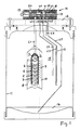
- einen senkrechten Schnitt durch die Vorrichtung mit oben aufgesetztem Mehrwegeventil und innen angeordnetem Behandlungsraum, wobei die Teile des Behandlungsraumes isometrisch dargestellt sind,
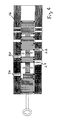
Figur 2- einen Schnitt durch das Mehrwegeventil in der Betriebsposition,
Figur 3- das Mehrwegeventil in der Mischposition,
Figur 4- das Mehrwegeventil in der geringen Behandlungsposition,
Figur 5- das Mehrwegeventil in der Regenerationsposition,
Figur 6- das Mehrwegeventil in der Spülposition und
Figur 7- das Mehrwegeventil in der Entschlammungsposition.
- Figure 1
- 3 shows a vertical section through the device with the multi-way valve placed on top and the treatment room arranged on the inside, the parts of the treatment room being shown isometrically,
- Figure 2
- a section through the multi-way valve in the operating position,
- Figure 3
- the multi-way valve in the mixing position,
- Figure 4
- the multi-way valve in the low treatment position,
- Figure 5
- the multi-way valve in the regeneration position,
- Figure 6
- the multi-way valve in the rinsing position and
- Figure 7
- the multi-way valve in the desludging position.
Die Vorrichtung weist ein senkrechtes Rohr 1 auf, das Öffnungen 2, insbesondere in Form von Schlitzen besitzt und einen Anodenraum 3 umschließt. Das Rohr 1 bildet eine Stütze für eine außenanliegende schraubenförmige Anode 4. Über der Anode liegt ein Gewebe 5, insbesondere ein Filterstrumpf, der dafür sorgt, daß das darüberliegende und um in einer Schicht angeordnete Ionenaustauschermaterial 6 nicht durch die Öffnungen 2 in den Anodenraum 3 gelangt. Das Ionenaustauschermaterial ist ein Harz, insbesondere in Form von Kügelchen und außen von einem Stahlgitter 7 umgeben.The device has a vertical tube 1, which has
In einem Abstand vom Gitter 7 ist koaxial ein Rohr 8 aus Kunststoff angeordnet, an dessen Innenseite eine Kathode 9 spiralförmig liegt. Damit befindet sich zwischen dem Rohr 8 als auch der Kathode 9 und der Schicht aus Ionenaustauschermaterial ein im Querschnitt ringförmiger Behandlungsraum 10, der nach oben und unten offen ist.At a distance from the
Die Teile 1 bis 10 befinden sich etwa in der Mitte eines zylindrischen Behälters 11, so daß das Rohr 8 rundum in einem etwa gleichgroßen Abstand zur Wand des Behälters 11 steht.The parts 1 to 10 are located approximately in the middle of a cylindrical container 11, so that the
Während der Behandlungsdauer fließt über die Leitung L1 die im Innern des Anodenraums 3 mündet, Rohwasser in den Anodenraum und läßt Calzium im Austausch gegen Wasserstoffionen im Harz des Ionenaustauschermaterials 6 zurück.During the treatment period, raw water flows into the anode compartment via the line L1, which opens into the interior of the
Im Regenerationsmodus wandern Wasserstoffionen von der Anode zur Kathode und verdrängen im Harz die Kalziumionen, die zur Kathode wandern und durch den hohen pH-Wert ausgeflockt werden.In the regeneration mode, hydrogen ions migrate from the anode to the cathode and displace the calcium ions in the resin, which migrate to the cathode and are flocculated by the high pH value.
Von der Oberseite des Behälters 11 ragen durch den oberen Behälterdeckel 12 neben der Wassereinlaßleitung L1 eine zweite Wassereinlaßleitung L2 nach unten in den Behälter, die etwa im mittleren Bereich des Behälters außerhalb des Rohres 8 mündet. Ferner ragt eine Wasserauslaßleitung L3 nach unten, die im unteren Bereich mündet und im oberen Bereich mindestens eine weitere Einlaßöffnung 13 besitzt. Im oberen Bereich mündet eine Entlüftungsleitung L4 und schließlich mündet im untersten Bereich, d.h. im Absetzraum 14 eine Entschlammungsleitung L5. Die Leitungen L2 bis L5 laufen somit durch den Außenraum (Vorratsraum) 15, der sich rundum um das Rohr 8 befindet.From the top of the container 11, a second water inlet line L2 projects downward into the container through the
Alle Leitungen L1 bis L5 laufen durch den Deckel 12 und sind an einem Mehrwegeventil 16 angeschlossen, das an der Oberseite des Deckels 12 befestigt ist. An der Oberseite ist das Mehrwegeventil 16 an einen Rohwassereinlauf 20, ein Wasserauslauf 21, eine Entlüftungsleitung 22, eine Entschlammungsleitung 23 und eine Entlüftung 24 für den Anodenraum angeschlossen. Das Mehrwegeventil 16 besitzt ein Ventilstellglied 17 mit mehreren einzelnen Kolben 18 auf einer Ventilstange 19. Durch Verstellen der Ventilstange 19 in mehreren Stellungen können die nachstehenden Positionen und damit Arbeitsweisen der Vorrichtung erzielt werden.Das Verstellen des Ventilstellgliedes 17 und damit der Kolbenstange 19 geschieht vorzugsweise durch eine elektrische Verstellvorrichtung, die durch eine elektronische Vorrichtung geregelt/gesteuert sein kann:All lines L1 to L5 run through the
In der in Figur 2 dargestellten Betriebsposition sind die Leitungen L2, L4 und L5 geschlossen und durch die Leitung L1 wird Rohwasser in den Anodenraum geführt und über die Leitung L3 das behandelte Wasser abgelassen.In the operating position shown in FIG. 2, lines L2, L4 and L5 are closed and raw water is fed through line L1 into the anode compartment and the treated water is drained off via line L3.
In dieser Stellung sind die Leitungen L4 und L5 geschlossen und Rohwasser wird sowohl durch die Leitung L1 als auch durch die Leitung L2 eingelassen, so daß ein Teil des Rohwassers in den Anodenraum und ein Teil in den Außenraum gelangt. Dadurch entsteht ein geringerer Behandlungseffekt, so daß sichergestellt wird, daß das austretende Wasser nicht zu stark behandelt ist.In this position, the lines L4 and L5 are closed and raw water is let in through both the line L1 and the line L2, so that part of the raw water gets into the anode compartment and part into the outside space. This results in a lower treatment effect, so that it is ensured that the escaping water is not treated too strongly.
In dieser Stellung sind die Leitungen L1, L4 und L5 geschlossen und das Rohwasser tritt nur durch die Leitung L2 ein und gelangt damit nur in den Außenraum 15, so daß die geringstmögliche Behandlung erzielt wird. Das behandelte Wasser tritt wiederum durch die Leitung L3 aus. Um den Grad der Behandlung zu vergleichmäßigen, kann die Vorrichtung durch eine Steuer- oder Regeleinrichtung zwischen den Positionen I bis III hin und her wechseln.In this position, the lines L1, L4 and L5 are closed and the raw water only enters through the line L2 and thus only reaches the
Die Leitungen L2, L3 und L5 sind geschlossen und eine gleichgerichtete Spannung liegt zwischen Anode und Kathode an. Durch Ionenwanderung verdrängen die Wasserstoffionen die auf dem Ionentauschermaterial 6 adsorbierten anderen Kathionen (z.B. Calzium) und im Außen- 10 und Behandlungsraum 15 steigen die Konzentrationen der Kathionen und Hydroxyionen, so daß es zu einer gleichzeitigen Regeneration des Ionentauschermaterials und zu einer Austrocknung von Hydroxiden und Carbonaten im Außen- und Behandlungsraum und zum Absinken derselben in den Absetzraum 14 kommt.The lines L2, L3 and L5 are closed and a rectified voltage is present between the anode and cathode. Due to ion migration, the hydrogen ions displace the other cathions (e.g. calcium) adsorbed on the
Im Anodenraum 3 konzentrieren sich die Anionen, z.B. Chlorid, Nitrat usw.The anions, e.g. Chloride, nitrate, etc.
Während der Regenerationszeit wird eine kontinuierliche Wasserentnahme durch eine parallelgeschaltete Vorrichtung gewährleistet.During the regeneration period, continuous water withdrawal is ensured by a device connected in parallel.
Die Leitungen L3, L4 und L5 sind geschlossen und über die Leitung L2 tritt Rohwasser ein und über die Leitung L1 wird das Wasser aus dem Anodenraum 3 verdrängt, wodurch die unerwünschten Anionen ausgespült werden. Dieser Zustand dauert nur Sekunden.Lines L3, L4 and L5 are closed and raw water enters via line L2 and is via line L1 displaces the water from the
Die Leitungen L2, L3 und L4 sind geschlossen und durch die Leitung L1 wird Rohwasser eingedrückt und durch die Leitung L5 Schlamm herausgedrückt. Auch dieser Zustand dauert nur Sekunden.Lines L2, L3 and L4 are closed and raw water is pressed in through line L1 and sludge is pressed out through line L5. This state also lasts only seconds.
Claims (17)
Priority Applications (1)
| Application Number | Priority Date | Filing Date | Title |
|---|---|---|---|
| DE9116999U DE9116999U1 (en) | 1990-06-20 | 1991-06-14 | Device for treating water |
Applications Claiming Priority (2)
| Application Number | Priority Date | Filing Date | Title |
|---|---|---|---|
| DE19904019580 DE4019580A1 (en) | 1989-06-21 | 1990-06-20 | Device for electrochemically sepg. and removing ions from liq. - uses two electrodes to apply an electric potential across an ion exchange material, causing ions to be pptd. |
| DE4019580 | 1990-06-20 |
Publications (2)
| Publication Number | Publication Date |
|---|---|
| EP0462523A1 true EP0462523A1 (en) | 1991-12-27 |
| EP0462523B1 EP0462523B1 (en) | 1994-08-31 |
Family
ID=6408692
Family Applications (1)
| Application Number | Title | Priority Date | Filing Date |
|---|---|---|---|
| EP91109794A Expired - Lifetime EP0462523B1 (en) | 1990-06-20 | 1991-06-14 | Apparatus and process for water treatment |
Country Status (8)
| Country | Link |
|---|---|
| US (1) | US5183565A (en) |
| EP (1) | EP0462523B1 (en) |
| JP (1) | JP3236637B2 (en) |
| AT (1) | ATE110588T1 (en) |
| CA (1) | CA2044862C (en) |
| DE (1) | DE59102710D1 (en) |
| DK (1) | DK0462523T3 (en) |
| ES (1) | ES2058991T3 (en) |
Families Citing this family (9)
| Publication number | Priority date | Publication date | Assignee | Title |
|---|---|---|---|---|
| US5364527A (en) * | 1990-06-20 | 1994-11-15 | Heinz Zimmermann | Apparatus and process for treating water |
| US6024850A (en) * | 1993-10-27 | 2000-02-15 | Halox Technologies Corporation | Modified ion exchange materials |
| US6402916B1 (en) | 1993-10-27 | 2002-06-11 | Richard L. Sampson | Electrolytic process and apparatus controlled regeneration of modified ion exchangers to purify aqueous solutions and adjust ph |
| US5419816A (en) * | 1993-10-27 | 1995-05-30 | Halox Technologies Corporation | Electrolytic process and apparatus for the controlled oxidation of inorganic and organic species in aqueous solutions |
| US5705050A (en) * | 1996-04-29 | 1998-01-06 | Sampson; Richard L. | Electrolytic process and apparatus for the controlled oxidation and reduction of inorganic and organic species in aqueous solutions |
| US5443709A (en) * | 1993-12-17 | 1995-08-22 | Imsco, Inc. | Apparatus for separating caffeine from a liquid containing the same |
| KR0152150B1 (en) * | 1995-08-31 | 1998-10-01 | 김광호 | Water purifier |
| US20040203166A1 (en) * | 2003-04-11 | 2004-10-14 | Sullivan John Timothy | Electrolysis apparatus and method utilizing at least one coiled electrode |
| WO2010078576A2 (en) | 2009-01-05 | 2010-07-08 | Clean-Fuel Technologies, Inc | Hydrogen supplementation fuel apparatus and method |
Citations (2)
| Publication number | Priority date | Publication date | Assignee | Title |
|---|---|---|---|---|
| GB809685A (en) * | 1955-05-12 | 1959-03-04 | Gen Electric | Improvements relating to water demineralizing units particularly for domestic supplysystems |
| DE3441419C1 (en) * | 1984-11-13 | 1986-06-05 | Hanns-Heinz 7034 Gärtringen Eumann | Apparatus for the electrodialytic demineralisation of water |
Family Cites Families (23)
| Publication number | Priority date | Publication date | Assignee | Title |
|---|---|---|---|---|
| US2793183A (en) * | 1954-07-15 | 1957-05-21 | Clayton Manufacturing Co | Electrolytic and ion exchange treatment of water |
| US2794777A (en) * | 1956-08-27 | 1957-06-04 | Clayton Manufacturing Co | Electrolytic deionization |
| US3074863A (en) * | 1958-05-01 | 1963-01-22 | Gen Electric | Processes of and apparatus for treating ionic liquids |
| JPS5128938B1 (en) * | 1970-11-26 | 1976-08-23 | ||
| US3847765A (en) * | 1972-12-20 | 1974-11-12 | Mitsubishi Petrochemical Co | Method for the treatment of cyanide-containing wastes |
| DE2424091C3 (en) * | 1974-05-17 | 1980-11-27 | Sachs Systemtechnik Gmbh, 8720 Schweinfurt | Process for anodic oxidation of organic pollutants in water in a fluidized bed made of conductive adsorbent |
| US4159235A (en) * | 1976-11-22 | 1979-06-26 | Gotzelmann Kg | Method and apparatus for treating metal containing waste water |
| US4326935A (en) * | 1978-11-06 | 1982-04-27 | Innova, Inc. | Electrochemical processes utilizing a layered membrane |
| US4403039A (en) * | 1980-10-29 | 1983-09-06 | Yokogawa Hokushin Electric Works | Method and apparatus for analysis of ionic species |
| JPS57106490U (en) * | 1980-12-23 | 1982-06-30 | ||
| US4670118A (en) * | 1981-01-02 | 1987-06-02 | Dorr-Oliver Incorporated | Electrode assembly and process for electrically augmented vacuum filtration |
| DE3341242A1 (en) * | 1983-11-15 | 1985-05-30 | Vereinigte Elektrizitätswerke Westfalen AG, 4600 Dortmund | DEVICE FOR ELECTROCHEMICAL OXYGEN REMOVAL FROM WATER |
| GB8332088D0 (en) * | 1983-12-01 | 1984-02-08 | Atomic Energy Authority Uk | Electrochemical deionization |
| US4758319A (en) * | 1985-05-24 | 1988-07-19 | Dorr-Oliver Incorporated | Dialyzing crossflow electrofilter with improved electrode |
| US4668361A (en) * | 1985-05-24 | 1987-05-26 | Dorr-Oliver Incorporated | Dialyzing electrofilter with improved electrode |
| FR2592317B1 (en) * | 1986-01-02 | 1988-04-22 | Univ Languedoc | METHOD FOR REGULATING AN ELECTRODIALYZER AND IMPROVED ELECTRODIALYSIS INSTALLATION. |
| US4879045A (en) * | 1986-01-13 | 1989-11-07 | Eggerichs Terry L | Method and apparatus for electromagnetically treating a fluid |
| DE3767359D1 (en) * | 1986-05-16 | 1991-02-21 | Electroplating Eng | METHOD AND DEVICE FOR RECOVERING A PRECIOUS METAL COMPOUND. |
| DE3640020C1 (en) * | 1986-11-24 | 1988-02-18 | Heraeus Elektroden | Electrolysis cell for the electrolytic deposition of metals |
| DE3805813A1 (en) * | 1987-07-09 | 1989-03-30 | Gruenbeck Josef Wasseraufb | METHOD AND DEVICE FOR REGENERATING ION EXCHANGER MATERIAL |
| US4929359A (en) * | 1988-01-26 | 1990-05-29 | The United States Of America As Represented By The United States Department Of Energy | Treatment of concentrated industrial wastewaters originating from oil shale and the like by electrolysis polyurethane foam interaction |
| US4865747A (en) * | 1988-01-27 | 1989-09-12 | Aqua-D Corp. | Electromagnetic fluid treating device and method |
| US5026465A (en) * | 1989-08-03 | 1991-06-25 | Ionics, Incorporated | Electrodeionization polarity reversal apparatus and process |
-
1991
- 1991-06-14 AT AT91109794T patent/ATE110588T1/en not_active IP Right Cessation
- 1991-06-14 DE DE59102710T patent/DE59102710D1/en not_active Expired - Fee Related
- 1991-06-14 EP EP91109794A patent/EP0462523B1/en not_active Expired - Lifetime
- 1991-06-14 ES ES91109794T patent/ES2058991T3/en not_active Expired - Lifetime
- 1991-06-14 DK DK91109794.7T patent/DK0462523T3/en active
- 1991-06-18 US US07/717,017 patent/US5183565A/en not_active Expired - Lifetime
- 1991-06-18 CA CA002044862A patent/CA2044862C/en not_active Expired - Fee Related
- 1991-06-19 JP JP14728591A patent/JP3236637B2/en not_active Expired - Fee Related
Patent Citations (2)
| Publication number | Priority date | Publication date | Assignee | Title |
|---|---|---|---|---|
| GB809685A (en) * | 1955-05-12 | 1959-03-04 | Gen Electric | Improvements relating to water demineralizing units particularly for domestic supplysystems |
| DE3441419C1 (en) * | 1984-11-13 | 1986-06-05 | Hanns-Heinz 7034 Gärtringen Eumann | Apparatus for the electrodialytic demineralisation of water |
Also Published As
| Publication number | Publication date |
|---|---|
| US5183565A (en) | 1993-02-02 |
| JP3236637B2 (en) | 2001-12-10 |
| ES2058991T3 (en) | 1994-11-01 |
| JPH04227073A (en) | 1992-08-17 |
| EP0462523B1 (en) | 1994-08-31 |
| CA2044862C (en) | 2001-05-01 |
| DK0462523T3 (en) | 1995-01-23 |
| DE59102710D1 (en) | 1994-10-06 |
| ATE110588T1 (en) | 1994-09-15 |
| CA2044862A1 (en) | 1991-12-21 |
Similar Documents
| Publication | Publication Date | Title |
|---|---|---|
| DE1942698C3 (en) | Method and device for the multi-stage biological treatment of waste water | |
| EP0345669B1 (en) | Process and device for activated biological waste water treatment | |
| EP0462523B1 (en) | Apparatus and process for water treatment | |
| DE3805813C2 (en) | ||
| DE2045377A1 (en) | Waste water filter | |
| WO2004030855A1 (en) | Cleaning gas device cleaning the process gas of a reflow soldering system | |
| DE2159811C2 (en) | Method and device for water treatment | |
| DE112016001462T5 (en) | Method for biological wastewater treatment with phosphorus removal | |
| DE2150915C2 (en) | Filter system for the separation of solids contained in a liquid | |
| EP0063236B1 (en) | Device for treating wash waters with ion-exchangers | |
| CH644569A5 (en) | METHOD AND DEVICE FOR TREATING WASTEWATER. | |
| DE4104094A1 (en) | Procedure and device for pre-clearing waste liq. such as pig slurry - after removal of coarse solid material, water undergoes ozonisation and electrolysis in prepn. for biological treatment | |
| DE4235834C2 (en) | Device for treating waste water | |
| EP0187880B1 (en) | Process and apparatus for the treatment of liquids, particularly the deionisation of aqueous solutions | |
| DE2420744C3 (en) | Device for purifying waste water | |
| DE2156426B2 (en) | ion exchange column | |
| DE4235833C2 (en) | Device and method for water purification | |
| EP0222180A2 (en) | Process and apparatus for backwashing a solid-bed ion exchanger | |
| DE1584917C3 (en) | Sewage treatment plant for chemical and biological purification of refinery and chemical wastewater | |
| DE4019580A1 (en) | Device for electrochemically sepg. and removing ions from liq. - uses two electrodes to apply an electric potential across an ion exchange material, causing ions to be pptd. | |
| EP0616822B1 (en) | Process for operating an adsorber and device for performing the process | |
| DE2035427C3 (en) | Device for equalizing the concentration of a solution that occurs with an intermittently changing concentration | |
| DE939384C (en) | Operating procedure for devices consisting of anode, cathode and intermediate diaphragms for cleaning liquids by electroosmosis | |
| DE3116623A1 (en) | METHOD AND DEVICE FOR OBTAINING DISPERSE PHASES FROM DISPERSIONS | |
| DE3241682A1 (en) | Process and equipment for treating liquids, in particular for desalinating aqueous solutions |
Legal Events
| Date | Code | Title | Description |
|---|---|---|---|
| PUAI | Public reference made under article 153(3) epc to a published international application that has entered the european phase |
Free format text: ORIGINAL CODE: 0009012 |
|
| AK | Designated contracting states |
Kind code of ref document: A1 Designated state(s): AT BE CH DE DK ES FR GB GR IT LI LU NL SE |
|
| 17P | Request for examination filed |
Effective date: 19911217 |
|
| 17Q | First examination report despatched |
Effective date: 19921120 |
|
| GRAA | (expected) grant |
Free format text: ORIGINAL CODE: 0009210 |
|
| AK | Designated contracting states |
Kind code of ref document: B1 Designated state(s): AT BE CH DE DK ES FR GB GR IT LI LU NL SE |
|
| REF | Corresponds to: |
Ref document number: 110588 Country of ref document: AT Date of ref document: 19940915 Kind code of ref document: T |
|
| ET | Fr: translation filed | ||
| REF | Corresponds to: |
Ref document number: 59102710 Country of ref document: DE Date of ref document: 19941006 |
|
| ITF | It: translation for a ep patent filed |
Owner name: SOCIETA' ITALIANA BREVETTI S.P.A. |
|
| REG | Reference to a national code |
Ref country code: ES Ref legal event code: FG2A Ref document number: 2058991 Country of ref document: ES Kind code of ref document: T3 |
|
| GBT | Gb: translation of ep patent filed (gb section 77(6)(a)/1977) |
Effective date: 19941003 |
|
| REG | Reference to a national code |
Ref country code: GR Ref legal event code: FG4A Free format text: 3013418 |
|
| REG | Reference to a national code |
Ref country code: DK Ref legal event code: T3 |
|
| EAL | Se: european patent in force in sweden |
Ref document number: 91109794.7 |
|
| PG25 | Lapsed in a contracting state [announced via postgrant information from national office to epo] |
Ref country code: LU Free format text: LAPSE BECAUSE OF NON-PAYMENT OF DUE FEES Effective date: 19950630 |
|
| PLBE | No opposition filed within time limit |
Free format text: ORIGINAL CODE: 0009261 |
|
| STAA | Information on the status of an ep patent application or granted ep patent |
Free format text: STATUS: NO OPPOSITION FILED WITHIN TIME LIMIT |
|
| 26N | No opposition filed | ||
| REG | Reference to a national code |
Ref country code: GB Ref legal event code: IF02 |
|
| PGFP | Annual fee paid to national office [announced via postgrant information from national office to epo] |
Ref country code: DK Payment date: 20020619 Year of fee payment: 12 |
|
| PGFP | Annual fee paid to national office [announced via postgrant information from national office to epo] |
Ref country code: SE Payment date: 20020624 Year of fee payment: 12 |
|
| PGFP | Annual fee paid to national office [announced via postgrant information from national office to epo] |
Ref country code: NL Payment date: 20020628 Year of fee payment: 12 |
|
| PG25 | Lapsed in a contracting state [announced via postgrant information from national office to epo] |
Ref country code: SE Free format text: LAPSE BECAUSE OF NON-PAYMENT OF DUE FEES Effective date: 20030615 |
|
| PGFP | Annual fee paid to national office [announced via postgrant information from national office to epo] |
Ref country code: CH Payment date: 20030619 Year of fee payment: 13 |
|
| PG25 | Lapsed in a contracting state [announced via postgrant information from national office to epo] |
Ref country code: DK Free format text: LAPSE BECAUSE OF NON-PAYMENT OF DUE FEES Effective date: 20030630 |
|
| PG25 | Lapsed in a contracting state [announced via postgrant information from national office to epo] |
Ref country code: NL Free format text: LAPSE BECAUSE OF NON-PAYMENT OF DUE FEES Effective date: 20040101 |
|
| EUG | Se: european patent has lapsed | ||
| REG | Reference to a national code |
Ref country code: DK Ref legal event code: EBP |
|
| NLV4 | Nl: lapsed or anulled due to non-payment of the annual fee |
Effective date: 20040101 |
|
| PGFP | Annual fee paid to national office [announced via postgrant information from national office to epo] |
Ref country code: FR Payment date: 20040625 Year of fee payment: 14 |
|
| PGFP | Annual fee paid to national office [announced via postgrant information from national office to epo] |
Ref country code: GR Payment date: 20040628 Year of fee payment: 14 Ref country code: AT Payment date: 20040628 Year of fee payment: 14 |
|
| PG25 | Lapsed in a contracting state [announced via postgrant information from national office to epo] |
Ref country code: LI Free format text: LAPSE BECAUSE OF NON-PAYMENT OF DUE FEES Effective date: 20040630 Ref country code: CH Free format text: LAPSE BECAUSE OF NON-PAYMENT OF DUE FEES Effective date: 20040630 |
|
| PGFP | Annual fee paid to national office [announced via postgrant information from national office to epo] |
Ref country code: ES Payment date: 20040719 Year of fee payment: 14 |
|
| PGFP | Annual fee paid to national office [announced via postgrant information from national office to epo] |
Ref country code: GB Payment date: 20040812 Year of fee payment: 14 |
|
| PGFP | Annual fee paid to national office [announced via postgrant information from national office to epo] |
Ref country code: BE Payment date: 20040813 Year of fee payment: 14 |
|
| PGFP | Annual fee paid to national office [announced via postgrant information from national office to epo] |
Ref country code: DE Payment date: 20040819 Year of fee payment: 14 |
|
| REG | Reference to a national code |
Ref country code: CH Ref legal event code: PL |
|
| PG25 | Lapsed in a contracting state [announced via postgrant information from national office to epo] |
Ref country code: IT Free format text: LAPSE BECAUSE OF NON-PAYMENT OF DUE FEES Effective date: 20050614 Ref country code: AT Free format text: LAPSE BECAUSE OF NON-PAYMENT OF DUE FEES Effective date: 20050614 |
|
| PG25 | Lapsed in a contracting state [announced via postgrant information from national office to epo] |
Ref country code: ES Free format text: LAPSE BECAUSE OF NON-PAYMENT OF DUE FEES Effective date: 20050615 |
|
| PG25 | Lapsed in a contracting state [announced via postgrant information from national office to epo] |
Ref country code: BE Free format text: LAPSE BECAUSE OF NON-PAYMENT OF DUE FEES Effective date: 20050630 |
|
| PG25 | Lapsed in a contracting state [announced via postgrant information from national office to epo] |
Ref country code: GR Free format text: LAPSE BECAUSE OF NON-PAYMENT OF DUE FEES Effective date: 20060103 Ref country code: DE Free format text: LAPSE BECAUSE OF NON-PAYMENT OF DUE FEES Effective date: 20060103 |
|
| PG25 | Lapsed in a contracting state [announced via postgrant information from national office to epo] |
Ref country code: FR Free format text: LAPSE BECAUSE OF NON-PAYMENT OF DUE FEES Effective date: 20060228 |
|
| GBPC | Gb: european patent ceased through non-payment of renewal fee |
Effective date: 20050614 |
|
| REG | Reference to a national code |
Ref country code: FR Ref legal event code: ST Effective date: 20060228 |
|
| REG | Reference to a national code |
Ref country code: ES Ref legal event code: FD2A Effective date: 20050615 |
|
| BERE | Be: lapsed |
Owner name: *MANTEUFFEL HANS J.M. Effective date: 20050630 Owner name: *ZIMMERMANN HEINZ Effective date: 20050630 |