EP0462489B1 - Conveying device for harvesting machines - Google Patents
Conveying device for harvesting machines Download PDFInfo
- Publication number
- EP0462489B1 EP0462489B1 EP91109516A EP91109516A EP0462489B1 EP 0462489 B1 EP0462489 B1 EP 0462489B1 EP 91109516 A EP91109516 A EP 91109516A EP 91109516 A EP91109516 A EP 91109516A EP 0462489 B1 EP0462489 B1 EP 0462489B1
- Authority
- EP
- European Patent Office
- Prior art keywords
- conveying
- conveyor
- tines
- conveying device
- slots
- Prior art date
- Legal status (The legal status is an assumption and is not a legal conclusion. Google has not performed a legal analysis and makes no representation as to the accuracy of the status listed.)
- Expired - Lifetime
Links
- 238000003306 harvesting Methods 0.000 title claims description 5
- 239000000463 material Substances 0.000 claims description 12
- 238000011144 upstream manufacturing Methods 0.000 claims description 2
- 238000010276 construction Methods 0.000 claims 1
- 230000015572 biosynthetic process Effects 0.000 description 13
- 238000000034 method Methods 0.000 description 10
- 230000000694 effects Effects 0.000 description 3
- 238000003825 pressing Methods 0.000 description 3
- 239000007858 starting material Substances 0.000 description 2
- 244000025254 Cannabis sativa Species 0.000 description 1
- 230000007423 decrease Effects 0.000 description 1
- 238000004519 manufacturing process Methods 0.000 description 1
- 239000002184 metal Substances 0.000 description 1
- 230000001737 promoting effect Effects 0.000 description 1
- 239000010902 straw Substances 0.000 description 1
- 230000032258 transport Effects 0.000 description 1
Images

Classifications
-
- A—HUMAN NECESSITIES
- A01—AGRICULTURE; FORESTRY; ANIMAL HUSBANDRY; HUNTING; TRAPPING; FISHING
- A01F—PROCESSING OF HARVESTED PRODUCE; HAY OR STRAW PRESSES; DEVICES FOR STORING AGRICULTURAL OR HORTICULTURAL PRODUCE
- A01F15/00—Baling presses for straw, hay or the like
- A01F15/08—Details
- A01F15/10—Feeding devices for the crop material e.g. precompression devices
- A01F15/106—Feeding devices for the crop material e.g. precompression devices for round balers
Definitions
- the invention relates to a conveying device for a harvesting machine, in particular for a baler, with a conveying base having slots and guided in the slots and during the conveying process emerging from these conveying tines, which have a leading end face.
- a known conveyor device on a baler for forming round bales (US Pat. No. 4,580,398) has a conveyor base which is penetrated by slots and is moved on the picked crop by a conveyor, namely a pick-up, to a bale forming chamber.
- Conveyor tines extend through the slots and carry out a controlled movement while transporting the crop.
- the tips of the conveying tines essentially describe an oval which runs with one of its longitudinal sides parallel to the surface of the conveying floor.
- the object on which the invention is based is seen in proposing a conveyor device of the type mentioned at the outset in which blockages are at least largely avoided.
- the material to be conveyed is held in the stair-like steps and can no longer slip back at the point located downstream during the delivery. After the material has slipped from one step to the next, it is only held by a smaller area of the conveyor tine, so that its frictional force decreases and the material slips faster to the delivery point.
- the effect of the steps on the conveyor tines can be increased even more by moving its movement in a controlled manner on a specific curve, so that the steps can take effect in a predeterminable range.
- steps as right-angled cuts represents the optimal shape, since it neither leads to snagging nor to a slightly aggressive conveying behavior; nevertheless, embodiments with cuts that are not at right angles are also possible.
- the legs of the steps themselves are at right angles to each other.
- the conveyor device according to the invention is not only advantageous when the goods are picked up directly from the ground, but also as an intermediate conveyor or as one of several conveyors within a conveyor chain.
- the conveyor can also be equipped with the advantageously designed conveyor tines.
- a harvesting machine 10 shown in FIG. 1 in the manner of a baler essentially consists of a frame 12, a receiving device 14, a bale forming chamber 16 and a roller 18 designed as a starter roller.
- the baler 10 is used to press straw, hay, grass or similar crops, which are deposited in a field in swaths or are separated from them, into cylindrical bales, so-called round bales. It has a bale formation chamber 16 with a variable diameter and essentially corresponds in structure to a baler as described in US Pat. No. 4,428,282. However, it is also possible to base the invention on another type of baler, in particular one with a bale formation chamber that cannot be changed in size.
- the frame 12 comprises as essential components a chassis 20, side walls 22 and a drawbar 24 for connection to an agricultural tractor.
- the receiving device 14 is formed by a conveying device 36 and a conveyor 38 designed as a so-called pick-up, which picks up crops deposited on the ground in a swath by means of rotating conveying elements 26 and feeds them to the bale formation chamber 16 by means of the conveying device 36 according to the invention.
- a mower attachment could be used instead of the conveyor 38.
- the bale forming chamber 16 takes the form of a wedge in FIG. 1 and thus in its initial state, which is delimited laterally by a set of belts 28.
- Each set of belts 28 consists of a plurality of belts 28 arranged side by side, which are guided over rollers 30.
- One or more of the rollers 30 are rotated by a drive device 32 from the tractor and move the belts 28 in a certain direction.
- the belts 28 are tensioned in that some of the rollers 30 with the belts 28 running over them are laterally deflected by means of a tensioning device 34 designed as a spring. It can be seen from FIG. 1 that crop 16 is fed into the bale formation chamber and is rotated there by the opposing belts 28 in order to form a bale core.
- the belts 28 can avoid the tension on the tensioning device 34 with the rollers 30 assigned to them until the bale formation chamber 16 has taken up almost the entire space between the side walls 22; then the pressing process must be ended.
- the roller 18 is located in the lower region of the bale formation chamber 16, extends longitudinally between the two side walls 22, runs parallel to the rollers 30, does not change its position during the pressing process, always moves close to the surfaces of the belts 28 and is also by means of the Drive device 32 driven. Due to its position, the roller 18 assumes the function of a starter roller, ie it supports the formation of the bale core in the initial phase of the pressing process, by rotating the crop in the initially empty bale forming chamber 16; for this purpose, it moves in the opposite direction to the movement of the adjacent belts 28.
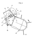
- the essential components of the conveyor device 36 include a conveyor floor 40, slots 42, conveyor tines 44 and a tine control 46. It follows downstream of the conveyor 38 and transports the crop into the bale formation chamber 16.
- the conveyor floor 40 is produced from a sheet metal and represents a sliding surface which adjoins the conveyor 38 and on which the crop slides.
- the slots 42 extend in the direction of movement of the conveying tines 44, that is to say in the conveying direction itself; they are slightly wider than the conveyor tines 44 in the area in which they pass through the conveyor floor 40 or the slots 42.
- the conveyor tines 44 are arranged parallel to one another in one or more rows and move together at least in groups.
- the conveying tines 44 extend over the entire width of the receiving device 14 and essentially have, apart from steps 56 to be described, the shape of a pointed wedge, the widest part 48 of which is always below the conveying floor 40 and thus always outside the conveying space and whose tip 50 runs above the conveyor base 40 during the conveying process.
- the conveyor tines 44 have a leading end face 52 and a trailing end face 54, which extend essentially transversely to the conveying plane. With the leading end face 52, the crop is grasped, which then lies against it until it is on the downstream delivery point disengages from the conveyor tines 44.
- leading end face 52 With the leading end face 52, a certain pressure resulting from the resistance to movement of the conveyed material via the conveying base 40 is exerted on the crop.
- the leading end face 52 does not run in a straight line, but in the form of a staircase, which is achieved in that L-shaped steps 56 are incorporated perpendicular to the end face 52.
- the legs of these steps run at an angle of approximately 90 ° to one another, the leg extending in the longitudinal direction of the conveyor tines 44 being several times longer than the leg running at right angles thereto.
- the trailing end face 54 can run both in a straight line and in steps 56. Since the trailing end face 54 only comes into engagement with the material to be conveyed at the end of the conveying process, the steps 56 can be omitted on this or a smaller number can be provided. However, there are no concerns about the tines 44 being mirror images, i. H. to be provided with two equally spaced steps 56 having end faces 52, 54.
- the conveying tines 44 extend during the conveying process, which takes place from right to left in FIG. 2, with their major part above the conveying floor 40, ie on the side remote from the tine control 46.
- the tip 50 of the conveying tines 44 describes an essentially oval curve and only retracts under the conveying floor 40 during a return.
- the conveying tines 44 extend slightly above the upstream conveyor 38 and preferably graze the effective area of the conveying elements 26 provided there.
- the tine control 46 is composed of a two-armed crank 58, a bearing 60 and an eccentric 62 with a pin 64.
- the conveyor tines 44 are pivotally mounted on the pin 64 and pivotally connected to the crank 58.
- the eccentric 62 transmits to the pin 64 a circular movement given to it, so that the conveyor tines 44 are moved perpendicular to the conveyor base 40.
- the position of the conveyor tines 44 depends on the angle which the arms of the crank 58 each enclose to one another. While the eccentric 62 rotates and thereby moves the conveyor tine or tines 44 perpendicular to the conveyor floor 40, the inclination of the conveyor tines 44 with respect to the surface of the conveyor floor 40 is also controlled by means of the two-armed crank 58. As a result, the tip 50 of the conveyor tines 44 describes the indicated oval cam track.
- the conveyor 38 Connected downstream of the conveyor device 36 is the conveyor 38, which is held in the manner of a conventional pick-up and contains ordinary conveyor elements 26; a detailed description of this conveyor 38 is therefore not required.
- the conveyor elements 26 could also be formed in the stepped, stepped form of the conveyor tines 44.
- the function of the conveyor device 36 is as follows.
- the conveyed material deposited on the ground as crop is picked up by the conveyor 38 and fed to the conveying tines 44 in FIG. 2 from bottom to top and from right to left by means of the conveying elements 26.
- the conveyor tines 44 move it in the same direction to the entrance of the Bale formation chamber 16, as indicated in FIG. 1, the tips of the conveying tines 44 describing the oval curved path shown.
- the conveyor tines 44 begin to retreat behind the conveyor floor 40 and as soon as the conveyed material is pulled out into the bale formation chamber 16, it slides away from the conveyor floor 40 on the leading end face 52 and settles in the next stage 56 until it closes the next stage 56. In this way, the material to be conveyed can no longer slide towards the conveyor floor 40, so that there is a positive conveying effect.
Landscapes
- Life Sciences & Earth Sciences (AREA)
- Environmental Sciences (AREA)
- Outside Dividers And Delivering Mechanisms For Harvesters (AREA)
- Apparatuses For Bulk Treatment Of Fruits And Vegetables And Apparatuses For Preparing Feeds (AREA)
Description
Die Erfindung betrifft eine Fördervorrichtung für eine Erntebergungsmaschine, insbesondere für eine Ballenpresse, mit einem Schlitze aufweisenden Förderboden und in den Schlitzen geführten und während des Fördervorgangs aus diesen heraustretenden Förderzinken, die eine voreilende Stirnfläche besitzen.The invention relates to a conveying device for a harvesting machine, in particular for a baler, with a conveying base having slots and guided in the slots and during the conveying process emerging from these conveying tines, which have a leading end face.
Eine bekannte Fördervorrichtung an einer Ballenpresse zum Bilden von Rundballen (US-PS-4,580,398) weist einen Förderboden auf, der von Schlitzen durchdrungen ist und auf dem aufgenommenes Erntegut von einem Förderer, nämlich einer Pick-Up, zu einer Ballenbildungskammer bewegt wird. Durch die Schlitze erstrecken sich Förderzinken, die eine gesteuerte Bewegung ausführen und dabei das Erntegut transportieren. Während des Fördervorgangs beschreiben die Spitzen der Förderzinken im wesentlichen ein Oval, das mit einer seiner Längsseiten parallel zu der Oberfläche des Förderbodens verläuft.A known conveyor device on a baler for forming round bales (US Pat. No. 4,580,398) has a conveyor base which is penetrated by slots and is moved on the picked crop by a conveyor, namely a pick-up, to a bale forming chamber. Conveyor tines extend through the slots and carry out a controlled movement while transporting the crop. During the conveying process, the tips of the conveying tines essentially describe an oval which runs with one of its longitudinal sides parallel to the surface of the conveying floor.
Die Förderwirkung dieser bekannten Förderzinken wird nicht unter allen Umständen als befriedigend angesehen; vielmehr können Verstopfungen am Eingang zu der Ballenbildungskammer auftreten.The promotional effect of these known production tines is not considered to be satisfactory in all circumstances; rather, blockages can occur at the entrance to the bale formation chamber.
Die der Erfindung zugrunde liegende Aufgabe wird darin gesehen, eine Fördervorrichtung der eingangs genannten Art vorzuschlagen, bei der Verstopfungen zumindest weitgehendst vermieden werden.The object on which the invention is based is seen in proposing a conveyor device of the type mentioned at the outset in which blockages are at least largely avoided.
Diese Aufgabe ist erfindungsgemäß durch die Merkmale des Patentanspruchs 1 gelöst worden, wobei in den weiteren Patentansprüchen Merkmale aufgeführt sind, die die Lösung in vorteilhafter Weise weiterentwickeln.This object has been achieved according to the invention by the features of patent claim 1, the others Features are listed that further develop the solution in an advantageous manner.
Auf diese Weise wird das zu fördernde Gut in den treppenartig ausgebildeten Stufen gehalten und kann während der Abgabe an der stromabwärts gelegenen Stelle nicht mehr zurückrutschen. Nachdem das Gut von einer Stufe auf die nächste gerutscht ist, wird es auch nur von einem kleineren Bereich des Förderzinkens gehalten, so daß dessen Reibkraft abnimmt und das Gut schneller zu der Abgabestelle rutscht.In this way, the material to be conveyed is held in the stair-like steps and can no longer slip back at the point located downstream during the delivery. After the material has slipped from one step to the next, it is only held by a smaller area of the conveyor tine, so that its frictional force decreases and the material slips faster to the delivery point.
Die Wirkung der Stufen an den Förderzinken kann noch erhöht werden, indem dessen Bewegung gesteuert auf einer bestimmten Kurve verläuft, so daß die Stufen in einem vorbestimmbaren Bereich wirksam werden können.The effect of the steps on the conveyor tines can be increased even more by moving its movement in a controlled manner on a specific curve, so that the steps can take effect in a predeterminable range.
Die Ausbildung der Stufen als rechtwinklige Einschnitte stellt die optimale Form dar, da sie weder zu Verhakungen noch zu einem gering aggressiven Förderverhalten führt; dennoch sind auch Ausführungsformen mit nicht rechtwinklig geführten Schnitten möglich. Auch die Schenkel der Stufen selbst verlaufen zueinander unter einem rechten Winkel.The formation of the steps as right-angled cuts represents the optimal shape, since it neither leads to snagging nor to a slightly aggressive conveying behavior; nevertheless, embodiments with cuts that are not at right angles are also possible. The legs of the steps themselves are at right angles to each other.
Die erfindungsgemäße Fördervorrichtung ist nicht nur vorteilhaft bei der direkten Aufnahme des Guts vom Boden, sondern auch als Zwischenförderer bzw. als einer von mehreren Förderern innerhalb einer Förderkette.The conveyor device according to the invention is not only advantageous when the goods are picked up directly from the ground, but also as an intermediate conveyor or as one of several conveyors within a conveyor chain.
Je nach den Einsatzverhältnissen kann auch der Förderer mit den vorteilhaft gestalteten Förderzinken ausgerüstet sein.Depending on the conditions of use, the conveyor can also be equipped with the advantageously designed conveyor tines.
In der Zeichnung ist ein nachfolgend näher beschriebenes Ausführungsbeispiel der Erfindung dargestellt. Es zeigt:
- Fig. 1
- eine Erntebergungsmaschine mit einer Fördervorrichtung und einem Förderer in schematischer Darstellung und in Seitenansicht
- Fig. 2
- die Fördervorrichtung und den Förderer aus Figur 1 in einer vergrößerten Darstellung.
- Fig. 1
- a harvesting machine with a conveyor and a conveyor in a schematic representation and in side view
- Fig. 2
- the conveyor and the conveyor of Figure 1 in an enlarged view.
Eine in Figur 1 dargestellte Erntebergungsmaschine 10 in der Art einer Ballenpresse setzt sich im wesentlichen aus einem Rahmen 12, einer Aufnahmevorrichtung 14, einer Ballenbildungskammer 16 und einer als Starterwalze ausgebildeten Walze 18 zusammen.A
Die Ballenpresse 10 wird benutzt, um Stroh, Heu, Gras oder dergleichen Erntegüter, die auf einem Feld in Schwade abgelegt sind oder von dort abgetrennt werden, in zylindrische Ballen, sogenannte Rundballen, zu pressen. Sie weist eine Ballenbildungskammer 16 mit veränderbarem Durchmesser auf und entspricht in ihrem Aufbau im wesentlichen einer Ballenpresse, wie sie in der US-PS-4,428,282 beschrieben ist. Es ist aber auch möglich, der Erfindung eine andere Bauart einer Ballenpresse zugrunde zu legen, insbesondere eine mit einer nicht in ihrer Größe veränderbaren Ballenbildungskammer.The
Der Rahmen 12 umfaßt als wesentliche Bestandteile ein Fahrwerk 20, Seitenwände 22 und eine Deichsel 24 zur Verbindung mit einem Ackerschlepper.The
Die Aufnahmevorrichtung 14 wird in dem vorliegenden Ausführungsbeispiel von einer Fördervorrichtung 36 und einem als sogenannte Pick-Up ausgebildeten Förderer 38 gebildet, der in einem Schwad auf dem Boden abgelegtes Erntegut mittels umlaufender Förderelemente 26 aufnimmt und es mittels der erfindungsgemäßen Fördervorrichtung 36 der Ballenbildungskammer 16 zuführt. In einem anderen Ausführungsbeispiel könnte anstatt des Förderers 38 auch ein Mähvorsatz verwendet werden.In the present exemplary embodiment, the
Die Ballenbildungskammer 16 nimmt in Figur 1 und somit in ihrem anfänglichen Zustand die Form eines Keils ein, der seitlich von einem Satz Riemen 28 begrenzt wird. Jeder Satz Riemen 28 besteht aus mehreren nebeneinander angeordneten Riemen 28, die über Rollen 30 geführt werden. Eine oder mehrere der Rollen 30 werden über eine Antriebsvorrichtung 32 von dem Ackerschlepper aus in Drehung versetzt und bewegen die Riemen 28 in eine bestimmt Richtung. Die Riemen 28 werden gespannt, indem mittels einer als Feder ausgebildeten Spannvorrichtung 34 einige der Rollen 30 mit den darüberlaufenden Riemen 28 seitlich ausgelenkt werden. Es ist aus Figur 1 zu entnehmen, daß in die Ballenbildungskammer 16 Erntegut eingespeist und dort von den gegenläufigen Riemen 28 in Drehung versetzt wird, um einen Ballenkern zu bilden. Während der Fahrt über das Feld wird mehr und mehr Erntegut der Ballenbildungskammer 16 zugeführt, so daß sich der Ballenkern vergrößert und die ihn umgebenden Riemen 28 seitlich auslenkt. Die Riemen 28 können unter Erhöhung der Spannung an der Spannvorrichtung 34 mit den ihnen zugeordneten Rollen 30 solange ausweichen, bis die Ballenbildungskammer 16 nahezu den gesamten Raum zwischen den Seitenwänden 22 eingenommen hat; dann ist der Preßvorgang zu beenden.The
Die Walze 18 befindet sich im unteren Bereich der Ballenbildungskammer 16, erstreckt sich längs zwischen den beiden Seitenwänden 22, verläuft parallelachsig zu den Rollen 30, verändert ihre Lage während des Preßvorgangs nicht, bewegt sich stets nahe der Oberflächen der Riemen 28 und wird ebenfalls mittels der Antriebsvorrichtung 32 angetrieben. Die Walze 18 nimmt aufgrund ihrer Lage die Funktion einer Starterwalze ein, d. h. sie unterstützt in der Anfangsphase des Preßvorgangs die Bildung des Ballenkerns, indem sie das Erntegut in der zunächst noch leeren Ballenbildungskammer 16 mit in Drehung versetzt; hierzu bewegt sie sich entgegengesetzt zu der Bewegungsrichtung der angrenzenden Riemen 28.The
Die Fördervorrichtung 36 enthält als wesentliche Bestandteile einen Förderboden 40, Schlitze 42, Förderzinken 44 und eine Zinkensteuerung 46. Sie folgt stromabwärts auf den Förderer 38 und transportiert das Erntegut in die Ballenbildungskammer 16.The essential components of the
Der Förderboden 40 wird aus einem Blech hergestellt und stellt eine Rutschfläche dar, die unmittelbar an den Förderer 38 anschließt und auf der das Erntegut entlanggleitet.The
Die Schlitze 42 erstrecken sich in der Bewegungsrichtung der Förderzinken 44, also in der Förderrichtung selbst; sie sind geringfügig breiter als die Förderzinken 44 in dem Bereich, in dem sie durch den Förderboden 40 bzw. die Schlitze 42 hindurchtreten.The
Die Förderzinken 44 sind in einer oder mehreren Reihen parallel zueinander angeordnet und bewegen sich zumindest in Gruppen gemeinsam. In ihrer Gesamtheit erstrecken sich die Förderzinken 44 über die gesamte Breite der Aufnahmevorrichtung 14 und weisen im wesentlichen, abgesehen von noch zu beschreibenden Stufen 56, die Form eines spitzen Keils auf, dessen breitester Teil 48 stets unterhalb des Förderbodens 40 und somit stets außerhalb des Förderraums und dessen Spitze 50 während des Fördervorgangs oberhalb des Förderbodens 40 verläuft. Die Förderzinken 44 weisen eine voreilende Stirnfläche 52 und eine nacheilende Stirnfläche 54 auf, die sich im wesentlichen quer zur Förderebene erstrecken. Mit der voreilenden Stirnfläche 52 wird das Erntegut erfaßt, das dann an ihr anliegt, bis es an der stromabwärts gelegenen Abgabestelle außer Eingriff mit den Förderzinken 44 gerät. Mit der voreilenden Stirnfläche 52 wird auf das Erntegut ein bestimmter, sich aus dem Bewegungswiderstand des Förderguts über den Förderboden 40 ergebender Druck ausgeübt. Die voreilende Stirnfläche 52 verläuft nicht geradlinig, sondern in der Form einer Treppe, was dadurch erreicht wird, daß senkrecht zu der Stirnfläche 52 L-förmige Stufen 56 eingearbeitet werden. Die Schenkel dieser Stufen verlaufen zueinander unter einem Winkel von ca. 90°, wobei der sich in der Längsrichtung der Förderzinken 44 erstreckende Schenkel um ein mehrfaches länger ist als der rechtwinklig dazu verlaufende Schenkel.The
Die nacheilende Stirnfläche 54 kann sowohl geradlinig wie auch in Stufen 56 abgesetzt verlaufen. Da die nacheilende Stirnfläche 54 erst am Ende des Fördervorgangs mit dem Fördergut in Eingriff gelangt, können an dieser die Stufen 56 entfallen oder in einer geringeren Anzahl vorgesehen werden. Es bestehen jedoch keine Bedenken, die Förderzinken 44 spiegelbildlich, d. h. mit zwei gleichermaßen abgesetzte Stufen 56 aufweisenden Stirnflächen 52, 54, zu versehen.The trailing
Die Förderzinken 44 erstrecken sich während des Fördervorgangs, der in Figur 2 von rechts nach links erfolgt, mit ihrem größten Teil oberhalb des Förderbodens 40, d. h. auf der der Zinkensteuerung 46 abgelegenen Seite. Während des Fördervorgangs beschreibt die Spitze 50 der Förderzinken 44 eine im wesentlichen ovale Kurve und zieht sich erst während eines Rückholgangs unter den Förderboden 40 zurück. Zu Beginn des Fördervorgangs reichen die Förderzinken 44 geringfügig über den stromaufwärts gelegenen Förderer 38 und streifen vorzugsweise die Wirkungsfläche der dort vorgesehenen Förderelemente 26.The
Die Zinkensteuerung 46 setzt sich aus einer zweiarmigen Kurbel 58, einer Lagerstelle 60 und einem Exzenter 62 mit einem Zapfen 64 zusammen. Die Förderzinken 44 sind auf dem Zapfen 64 schwenkbar gelagert und mit der Kurbel 58 schwenkbar verbunden. Der Exzenter 62 überträgt auf den Zapfen 64 eine ihm aufgegebene Kreisbewegung, so daß die Förderzinken 44 senkrecht zu dem Förderboden 40 bewegt werden. Die Stellung der Förderzinken 44 richtet sich nach dem Winkel, den die Arme der Kurbel 58 jeweils zueinander einschließen. Während sich der Exzenter 62 dreht und dabei den oder die Förderzinken 44 senkrecht zu dem Förderboden 40 bewegt, wird mittels der zweiarmigen Kurbel 58 auch die Neigung der Förderzinken 44 mit Bezug auf die Oberfläche des Förderbodens 40 gesteuert. Als Resultat beschreibt die Spitze 50 der Förderzinken 44 die angedeutete ovale Kurvenbahn.The
Stromabwärts der Fördervorrichtung 36 schließt der Förderer 38 an, der in der Art einer herkömmlichen Pick-Up gehalten ist und gewöhnliche Förderelemente 26 enthält; einer näheren Beschreibung dieses Förderers 38 bedarf es daher nicht. Es ist jedoch zu bemerken, daß die Förderelemente 26 auch in der abgesetzten, gestuften Form der Förderzinken 44 ausgebildet sein könnten.Connected downstream of the
Es ist nicht erforderlich, der Fördervorrichtung 36 einen Förderer 38 vorzuschalten; vielmehr könnte die Fördervorrichtung 36 das Fördergut auch direkt vom Boden aufnehmen.It is not necessary to connect a
Aufgrund des Vorbeschriebenen ergibt sich die Funktion der erfindungsgemäßen Fördervorrichtung 36 wie folgt. Das als Erntegut auf dem Boden abgelegte Fördergut wird von dem Förderer 38 aufgehoben und mittels der Förderelemente 26 den Förderzinken 44 in Figur 2 von unten nach oben und von rechts nach links zugeführt. Die Förderzinken 44 bewegen es in der gleichen Richtung weiter zu dem Eingang der Ballenbildungskammer 16, wie sie in Figur 1 angedeutet ist, wobei die Spitzen der Förderzinken 44 die gezeigte ovale Kurvenbahn beschreiben. Sobald die Förderzinken 44 beginnen, sich hinter den Förderboden 40 zurückzuziehen, sowie sobald das Fördergut in die Ballenbildungskammer 16 hinausgezogen wird, rutscht es von dem Förderboden 40 weg auf der voreilenden Stirnfläche 52 entlang und setzt sich in der nächsten Stufe 56 fest, bis es zu der nächsten Stufe 56 gelangt. Auf diese Weise kann das Fördergut nicht mehr zu dem Förderboden 40 hinrutschen, so daß sich ein positiver Fördereffekt ergibt.Based on what has been described above, the function of the
Claims (8)
- Conveying device (36) for a harvesting machine (10), in particular for a bale press, with a conveying base (40) comprising slots (42) and with conveying tines (44) which are guided in the slots (42) and emerge therefrom during the conveying operation and which have a leading face (52), characterised in that the conveying tines (44) comprise on their leading face (52) several steps (56) of staircase-like construction.
- Conveying device according to claim 1, characterised in that the steps (56) are formed by a notch extending perpendicularly to the surface of the leading face (52).
- Conveying device according to claim 1 or 2, characterised in that the conveying tines (44) describe an essentially oval path during the conveying operation, move out of the slots (42) at the beginning of the conveying movement, extend essentially parallel thereto during the conveying movement, and are retracted into the slots (42) at the end of the conveying movement.
- Conveying device according to one or more of the preceding claims, characterised in that upstream of it is mounted a conveyor (38), in particular a pick-up device, which picks up the material to be conveyed.
- Conveying device according to one or more of the preceding claims, characterised in that downstream of it is mounted a bale forming chamber (16).
- Conveying device according to claim 4, characterised in that the conveyor (38) comprises conveying elements (26) also protruding from slots, and the conveying tines (44) and the conveying elements (26) overlap each other or extend up to each other during transfer of the material.
- Conveying device according to one or more of the preceding claims, characterised in that both the conveying tines (44) and the conveying elements (26) comprise several staircase-like steps (56) on their side facing towards the material to be conveyed, i.e. their leading face (52).
- Conveying device according to one or more of the preceding claims, characterised in that steps (56) are also arranged on a trailing face (54).
Applications Claiming Priority (2)
| Application Number | Priority Date | Filing Date | Title |
|---|---|---|---|
| DE4019337 | 1990-06-18 | ||
| DE4019337A DE4019337A1 (en) | 1990-06-18 | 1990-06-18 | CONVEYOR DEVICE FOR A HARVESTING MACHINE |
Publications (3)
| Publication Number | Publication Date |
|---|---|
| EP0462489A2 EP0462489A2 (en) | 1991-12-27 |
| EP0462489A3 EP0462489A3 (en) | 1992-03-25 |
| EP0462489B1 true EP0462489B1 (en) | 1993-10-13 |
Family
ID=6408575
Family Applications (1)
| Application Number | Title | Priority Date | Filing Date |
|---|---|---|---|
| EP91109516A Expired - Lifetime EP0462489B1 (en) | 1990-06-18 | 1991-06-10 | Conveying device for harvesting machines |
Country Status (3)
| Country | Link |
|---|---|
| US (1) | US5163544A (en) |
| EP (1) | EP0462489B1 (en) |
| DE (2) | DE4019337A1 (en) |
Families Citing this family (1)
| Publication number | Priority date | Publication date | Assignee | Title |
|---|---|---|---|---|
| US5595055A (en) * | 1995-07-17 | 1997-01-21 | New Holland North America, Inc. | Pickup apparatus for a round baler |
Family Cites Families (13)
| Publication number | Priority date | Publication date | Assignee | Title |
|---|---|---|---|---|
| US2775339A (en) * | 1952-01-31 | 1956-12-25 | R Rousseau Sa Ets | Baler mechanism |
| US2744617A (en) * | 1955-02-17 | 1956-05-08 | Cockshutt Farm Equipment Ltd | Forage harvesters |
| DE1141125B (en) * | 1960-03-28 | 1962-12-13 | Etablissements Rivierre Casali | Agricultural harvesting machine, in particular collecting press |
| US3156346A (en) * | 1963-01-15 | 1964-11-10 | Sperry Rand Corp | Hay baler |
| FR1362069A (en) * | 1963-04-19 | 1964-05-29 | Thiebaud Bourguignonne | Baler-collector with bundle separation device |
| FR2231306B1 (en) * | 1973-05-28 | 1978-03-31 | Welger Geb | |
| US3914926A (en) * | 1974-05-22 | 1975-10-28 | Gehl Co | Rotary baling machine |
| US4488636A (en) * | 1980-08-30 | 1984-12-18 | Sperry Corporation | Feeder mechanism for agricultural baler |
| DE3311330C2 (en) * | 1983-03-29 | 1986-10-30 | Claas Ohg, 4834 Harsewinkel | Method and device for wrapping and wrapping a cylindrical crop bale |
| DE3432265A1 (en) * | 1984-09-01 | 1986-03-13 | Claas Ohg, 4834 Harsewinkel | DRIVABLE LARGE BALE PRESS FOR AGRICULTURAL HARVEST |
| DE3437294C2 (en) * | 1984-10-11 | 1994-02-17 | Claas Ohg | Baler for agricultural crops, especially roller balers |
| US4819418A (en) * | 1987-09-29 | 1989-04-11 | Hesston Corporation | Simplified crop baler |
| GB2227447A (en) * | 1989-01-30 | 1990-08-01 | Deere & Co | Machine for forming cylindrical bales of crop |
-
1990
- 1990-06-18 DE DE4019337A patent/DE4019337A1/en active Granted
-
1991
- 1991-06-10 DE DE91109516T patent/DE59100479D1/en not_active Expired - Lifetime
- 1991-06-10 EP EP91109516A patent/EP0462489B1/en not_active Expired - Lifetime
- 1991-06-18 US US07/717,156 patent/US5163544A/en not_active Expired - Lifetime
Also Published As
| Publication number | Publication date |
|---|---|
| EP0462489A3 (en) | 1992-03-25 |
| US5163544A (en) | 1992-11-17 |
| EP0462489A2 (en) | 1991-12-27 |
| DE4019337C2 (en) | 1992-10-22 |
| DE4019337A1 (en) | 1991-12-19 |
| DE59100479D1 (en) | 1993-11-18 |
Similar Documents
| Publication | Publication Date | Title |
|---|---|---|
| DE69323738T2 (en) | Bale press feed mechanism | |
| DE69709981T2 (en) | Round baler | |
| DE2851035C2 (en) | Crop round baler | |
| DE69905511T2 (en) | Round bale forming device | |
| EP0803184B1 (en) | Pick-up | |
| DE4019335C2 (en) | Bale press for forming cylindrical bales from a crop | |
| DE2443838A1 (en) | ROLL BALER | |
| DE69618393T2 (en) | Conveyor device for crop pickers | |
| EP1133913A2 (en) | Rotobaler | |
| EP2484197A1 (en) | Round baling press with side guides for the pressing belt | |
| DE2634638A1 (en) | Large dia. bale rolling press - has storage and coiling chambers separated by tiltable endless belt adjacent lower rollers of rolling belt | |
| EP0651940B2 (en) | Spring tine, conveyor device and harvesting machine | |
| DE69308059T2 (en) | Roller stripping device for a round baler | |
| DE932164C (en) | Baler | |
| EP0651939B1 (en) | Stripper of a (pick-up) conveying device of a harvesting machine | |
| DE68910003T2 (en) | Baler. | |
| WO2000001215A1 (en) | Pick-up baler for harvested agricultural produce | |
| DE2947442C2 (en) | ||
| EP0535532A2 (en) | Method of tying bales of crop and device therefor | |
| DE3134238C2 (en) | ||
| EP0197952A1 (en) | Process and device for producing large bales from cut plant materials | |
| DE68906068T2 (en) | ROUND BALE PRESS WITH VARIABLE CHAMBER AND TOWING DEVICE. | |
| EP0462489B1 (en) | Conveying device for harvesting machines | |
| DE2226368A1 (en) | Mobile baler | |
| DE3854411T2 (en) | Round baler with rollers and belts. |
Legal Events
| Date | Code | Title | Description |
|---|---|---|---|
| PUAI | Public reference made under article 153(3) epc to a published international application that has entered the european phase |
Free format text: ORIGINAL CODE: 0009012 |
|
| AK | Designated contracting states |
Kind code of ref document: A2 Designated state(s): DE DK ES FR GB IT NL SE |
|
| PUAL | Search report despatched |
Free format text: ORIGINAL CODE: 0009013 |
|
| AK | Designated contracting states |
Kind code of ref document: A3 Designated state(s): DE DK ES FR GB IT NL SE |
|
| 17P | Request for examination filed |
Effective date: 19920331 |
|
| 17Q | First examination report despatched |
Effective date: 19930311 |
|
| ITF | It: translation for a ep patent filed | ||
| GRAA | (expected) grant |
Free format text: ORIGINAL CODE: 0009210 |
|
| AK | Designated contracting states |
Kind code of ref document: B1 Designated state(s): DE DK ES FR GB IT NL SE |
|
| PG25 | Lapsed in a contracting state [announced via postgrant information from national office to epo] |
Ref country code: SE Effective date: 19931013 Ref country code: NL Effective date: 19931013 Ref country code: ES Free format text: THE PATENT HAS BEEN ANNULLED BY A DECISION OF A NATIONAL AUTHORITY Effective date: 19931013 Ref country code: DK Effective date: 19931013 |
|
| REF | Corresponds to: |
Ref document number: 59100479 Country of ref document: DE Date of ref document: 19931118 |
|
| GBT | Gb: translation of ep patent filed (gb section 77(6)(a)/1977) |
Effective date: 19931028 |
|
| RBV | Designated contracting states (corrected) |
Designated state(s): DK ES FR GB IT NL SE |
|
| ET | Fr: translation filed | ||
| NLV1 | Nl: lapsed or annulled due to failure to fulfill the requirements of art. 29p and 29m of the patents act | ||
| ITTA | It: last paid annual fee | ||
| PLBE | No opposition filed within time limit |
Free format text: ORIGINAL CODE: 0009261 |
|
| STAA | Information on the status of an ep patent application or granted ep patent |
Free format text: STATUS: NO OPPOSITION FILED WITHIN TIME LIMIT |
|
| 26N | No opposition filed | ||
| PG25 | Lapsed in a contracting state [announced via postgrant information from national office to epo] |
Ref country code: GB Effective date: 19950610 |
|
| GBPC | Gb: european patent ceased through non-payment of renewal fee |
Effective date: 19950610 |
|
| PG25 | Lapsed in a contracting state [announced via postgrant information from national office to epo] |
Ref country code: IT Free format text: LAPSE BECAUSE OF NON-PAYMENT OF DUE FEES;WARNING: LAPSES OF ITALIAN PATENTS WITH EFFECTIVE DATE BEFORE 2007 MAY HAVE OCCURRED AT ANY TIME BEFORE 2007. THE CORRECT EFFECTIVE DATE MAY BE DIFFERENT FROM THE ONE RECORDED. Effective date: 20050610 |
|
| PGFP | Annual fee paid to national office [announced via postgrant information from national office to epo] |
Ref country code: FR Payment date: 20060620 Year of fee payment: 16 |
|
| REG | Reference to a national code |
Ref country code: FR Ref legal event code: ST Effective date: 20080229 |
|
| PG25 | Lapsed in a contracting state [announced via postgrant information from national office to epo] |
Ref country code: FR Free format text: LAPSE BECAUSE OF NON-PAYMENT OF DUE FEES Effective date: 20070702 |