EP0462334B1 - A replaceable blade knife - Google Patents
A replaceable blade knife Download PDFInfo
- Publication number
- EP0462334B1 EP0462334B1 EP90306618A EP90306618A EP0462334B1 EP 0462334 B1 EP0462334 B1 EP 0462334B1 EP 90306618 A EP90306618 A EP 90306618A EP 90306618 A EP90306618 A EP 90306618A EP 0462334 B1 EP0462334 B1 EP 0462334B1
- Authority
- EP
- European Patent Office
- Prior art keywords
- handle
- handle portion
- portions
- aperture
- blade
- Prior art date
- Legal status (The legal status is an assumption and is not a legal conclusion. Google has not performed a legal analysis and makes no representation as to the accuracy of the status listed.)
- Expired - Lifetime
Links
Images


Classifications
-
- B—PERFORMING OPERATIONS; TRANSPORTING
- B26—HAND CUTTING TOOLS; CUTTING; SEVERING
- B26B—HAND-HELD CUTTING TOOLS NOT OTHERWISE PROVIDED FOR
- B26B5/00—Hand knives with one or more detachable blades
- B26B5/001—Hand knives with one or more detachable blades with blades being slid out of handle immediately prior to use
Definitions
- This invention relates to a replaceable blade knife comprising an elongate handle, formed by two elongate handle portions, and a blade carrier assembled together; the blade protruding, or being arranged to protrude, from a front end of the handle, between respective front ends of the two handle portions.
- US-A-4 240 202 discloses a replaceable blade knife comprising an elongate handle, formed by two elongate handle portions, and a blade carrier assembled together; the blade protruding, or being arranged to protrude, from a front end of the handle, between respective front ends of the two handle portions; the two handle portions interlocking together with each other at or near the front end of the handle to resist splaying apart thereof in the event of side loading of the blade; the two handle portions interlocking with each other also at or near the rear end of the handle, to prevent the two handle portions from being parted at the rear end of the handle; a first one of said two handle portions having an aperture through a rear end part thereof; said two handle portions being longitudinally displaceable relative to one another to disengage the interlocking together of the two handle portions and thereby allow separation of the two handle portions; the knife comprising selectively releasable means in the aperture for preventing, except when released, the longitudinal displacement of
- the illustrated replaceable blade knife 1 comprises an elongate handle 2 formed by two elongate handle portions 3, 4 of plastics material, namely, an upper handle portion 3 and a lower handle portion 4, and a blade carrier 5, assembled together.
- a blade 6 is mounted on the blade carrier 5, which is housed within the handle 2 and is adapted and arranged to slide along guides 7 within the handle 2 towards and away from the front end 8 of the handle 2, to extend and retract the blade 6. When extended, the blade 6 protrudes from the front end 8 of the handle 2 between respective front ends 9, 10 of the two handle portions 3, 4.
- the blade carrier 5 is provided with a resiliently biased button 11 which protrudes through an elongate slot 12 in the upper handle portion 3 for extending and retracting the blade 6, the button 11 being biased into releaseable engagement with internal detent formations 13 on the upper handle portion 3, at each side of the slot 12.
- the upper handle portion 3 is formed near its front end 9 with two downwardly projecting flank portions 14, 15 at the top and bottom sides of the upper handle portion 3 respectively, spaced rearwardly a little from the very front end 9 of the upper handle portion 3.
- Each said flank portion 14, 15 of the upper handle portion 3 has an integral, forwardly projecting piece 16, 17 at the bottom of the flank portion, to interlock with the lower handle portion 4 in a manner to be described.
- the upper handle portion 3 is cut away at 18 and 19 to receive upwardly projecting flank portions 20, 21 of the lower handle portion 4, in a manner to be described.
- the upper handle portion 3 has a thumb-nail-sized aperture 26 through a rear end part of the upper handle portion. At the rear edge of the aperture 26, the upper handle portion 3 is formed, at the bottom thereof, with a forwardly directed projection 27 which engages in a recess 28 at a rear wall 29 of the lower handle 4 portion to interlock the two handle portions 3, 4 together at the rear end of the handle 2, to prevent the two handle portions 3, 4 being parted at the rear end of the handle 2.
- the lower handle portion 4 has a resiliently deflectable, integrally formed latch part 31 which occupies the aperture 26 when the two handle portions 3, 4 are assembled together.
- the latch part 31 is in the form of a cantilever extending generally forwardly and at an angle to the plane of the blade 6, to protrude into the aperture 26, from its attachment point at 32 to the rear end of a main body part 33 of the lower handle portion 4.
- a front end 34 of the latch part 31 is of stepped formation, to provide a narrow, forwardly projecting, ledge 35. This front end 34 of the latch part 31 latchingly engages a front edge 36 of the aperture 26 when the two handle portions 3, 4 are assembled together.
- the front edge 36 of the aperture 26 in the upper handle portion 3 presses down upon the ledge 35 of the latch part 31, giving the latch part 31 a slight resilient deflection to maintain latching engagement.
- An internal, integral, resiliently flexible spring leaf 37 of the upper handle portion 3 projects downwardly from a top wall 38 of the upper handle portion, and longitudinally engages the rear of an internal rib 39 of the lower handle portion 4, so as to tend to push the lower handle portion 4 forwardly of the upper handle portion 3 and thereby bias the front end 34 of the latch part 31 longitudinally of the handle 2 into its latching engagement with the front edge 36 of the aperture 26.
- the flank portions 14, 15 at the front end of the upper handle portion fit generally behind the flank portions 20, 21 at the front end of the lower handle portion 4, interlocked by the lower handle portion flank portion pieces 22, 23 overlying the upper handle portion flank portion pieces 16, 17 as described above.
- the external or upper surface 40 of the latch part 31 follows the contour of the external or upper surface 41 of the upper handle portion 3 around the edge of the aperture 26, sloping relative to the plane of the blade 6.
- the latch part 31 is resiliently deflectable out of the latching engagement with the front edge 36 of the aperture 26 by a manual pressure applied to the upper surface 40 of the latch part 31 within the aperture 26.
- latch part 31 necessitates - due to the angle of the latch part 31 to the plane of the blade 6 - a very slight rearward movement of the lower handle portion 4 against the resilient bias of the spring leaf 32 of the upper handle portion 3.
- the two handle portions 3, 4 are thereupon longitudinally displaceable in the opposite direction relative to one another, the upper handle portion 3 moving rearwardly of the lower handle portion 4, to disengage the interlocking both at the front end and at the rear end of the handle 2 and thereby allow separation of the two handle portions 3, 4, for replacing the blade 6.
- the two handle portions 3, 4 are slid relatively longitudinally of one another, the upper handle portion 3 moving forwardly of the lower handle portion 4, until the latch part 31 clicks into latching engagement with the front edge 36 of the aperture 26 in the upper handle portion 3.
Landscapes
- Life Sciences & Earth Sciences (AREA)
- Forests & Forestry (AREA)
- Engineering & Computer Science (AREA)
- Mechanical Engineering (AREA)
- Knives (AREA)
Abstract
Description
- This invention relates to a replaceable blade knife comprising an elongate handle, formed by two elongate handle portions, and a blade carrier assembled together; the blade protruding, or being arranged to protrude, from a front end of the handle, between respective front ends of the two handle portions.
- The blade may or may not be extendable and retractable and may or may not be a snap-off blade, adapted for used bits of the blade to be snapped-off and discarded from time to time.
- US-A-4 240 202, on which the preamble of claim 1 is based, discloses a replaceable blade knife comprising an elongate handle, formed by two elongate handle portions, and a blade carrier assembled together;
the blade protruding, or being arranged to protrude, from a front end of the handle, between respective front ends of the two handle portions;
the two handle portions interlocking together with each other at or near the front end of the handle to resist splaying apart thereof in the event of side loading of the blade;
the two handle portions interlocking with each other also at or near the rear end of the handle, to prevent the two handle portions from being parted at the rear end of the handle;
a first one of said two handle portions having an aperture through a rear end part thereof;
said two handle portions being longitudinally displaceable relative to one another to disengage the interlocking together of the two handle portions and thereby allow separation of the two handle portions;
the knife comprising selectively releasable means in the aperture for preventing, except when released, the longitudinal displacement of the two handle portions. - The invention provides a replaceable blade knife as claimed in each of the claims, to which reference is directed.
- The invention will be described by way of example with reference to the drawings, wherein:-
- FIG. 1 is a front elevational view of a replaceable blade knife embodying the invention;
- FIG. 2 is a rear elevational view of the replaceable blade knife embodying the invention of Fig. 1;
- FIG. 3 is a section on III-III of Fig. 1;
- FIG. 4 is a top view of the knife of Figs. 1 to 3;
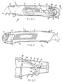
- FIG. 5 is an exploded underneath view of the knife of Figs. 1 to 4;
- FIG. 6 is a view of the insides of the two handle portions and the blade carrier with blade of the knife of Figs. 1 to 5; and
- FIGS. 7, 8 and 9 are respectively a front view, a side view and an end view of the blade carrier of the knife of Figs. 1 to 6.
- The illustrated replaceable blade knife 1 comprises an
elongate handle 2 formed by twoelongate handle portions upper handle portion 3 and alower handle portion 4, and ablade carrier 5, assembled together. Ablade 6 is mounted on theblade carrier 5, which is housed within thehandle 2 and is adapted and arranged to slide alongguides 7 within thehandle 2 towards and away from thefront end 8 of thehandle 2, to extend and retract theblade 6. When extended, theblade 6 protrudes from thefront end 8 of thehandle 2 between respectivefront ends 9, 10 of the twohandle portions blade carrier 5 is provided with a resilientlybiased button 11 which protrudes through anelongate slot 12 in theupper handle portion 3 for extending and retracting theblade 6, thebutton 11 being biased into releaseable engagement withinternal detent formations 13 on theupper handle portion 3, at each side of theslot 12. - The
upper handle portion 3 is formed near its front end 9 with two downwardly projectingflank portions upper handle portion 3 respectively, spaced rearwardly a little from the very front end 9 of theupper handle portion 3. Each saidflank portion upper handle portion 3 has an integral, forwardly projectingpiece lower handle portion 4 in a manner to be described. As shown in Fig. 6, theupper handle portion 3 is cut away at 18 and 19 to receive upwardly projectingflank portions lower handle portion 4, in a manner to be described. - The
lower handle portion 4 is formed at the very front thereof with the above-mentioned upwardly projectingflank portions flank portion lower handle portion 4 has an integral, rearwardly projectingpiece piece corresponding flank portion upper handle portion 3. As shown in Fig 6, thelower handle portion 4 is formed with tworecesses 24, 25 behind its twoflank portions flank portions upper handle portion 3, for interlocking the twohandle portions front end 8 of thehandle 2. - The
upper handle portion 3 has a thumb-nail-sizedaperture 26 through a rear end part of the upper handle portion. At the rear edge of theaperture 26, theupper handle portion 3 is formed, at the bottom thereof, with a forwardly directedprojection 27 which engages in arecess 28 at arear wall 29 of thelower handle 4 portion to interlock the twohandle portions handle 2, to prevent the twohandle portions handle 2. - The
lower handle portion 4 has a resiliently deflectable, integrally formedlatch part 31 which occupies theaperture 26 when the twohandle portions latch part 31 is in the form of a cantilever extending generally forwardly and at an angle to the plane of theblade 6, to protrude into theaperture 26, from its attachment point at 32 to the rear end of amain body part 33 of thelower handle portion 4. Afront end 34 of thelatch part 31 is of stepped formation, to provide a narrow, forwardly projecting, ledge 35. Thisfront end 34 of thelatch part 31 latchingly engages afront edge 36 of theaperture 26 when the twohandle portions front edge 36 of theaperture 26 in theupper handle portion 3 presses down upon theledge 35 of thelatch part 31, giving the latch part 31 a slight resilient deflection to maintain latching engagement. - An internal, integral, resiliently
flexible spring leaf 37 of theupper handle portion 3 projects downwardly from atop wall 38 of the upper handle portion, and longitudinally engages the rear of aninternal rib 39 of thelower handle portion 4, so as to tend to push thelower handle portion 4 forwardly of theupper handle portion 3 and thereby bias thefront end 34 of thelatch part 31 longitudinally of thehandle 2 into its latching engagement with thefront edge 36 of theaperture 26. - When the two
handle portions flank portions flank portions lower handle portion 4, interlocked by the lower handle portionflank portion pieces flank portion pieces upper surface 40 of thelatch part 31 follows the contour of the external orupper surface 41 of theupper handle portion 3 around the edge of theaperture 26, sloping relative to the plane of theblade 6. Thelatch part 31 is resiliently deflectable out of the latching engagement with thefront edge 36 of theaperture 26 by a manual pressure applied to theupper surface 40 of thelatch part 31 within theaperture 26. The disengagement oflatch part 31 necessitates - due to the angle of thelatch part 31 to the plane of the blade 6 - a very slight rearward movement of thelower handle portion 4 against the resilient bias of thespring leaf 32 of theupper handle portion 3. The twohandle portions upper handle portion 3 moving rearwardly of thelower handle portion 4, to disengage the interlocking both at the front end and at the rear end of thehandle 2 and thereby allow separation of the twohandle portions blade 6. - When the knife 1 is reassembled, the two
handle portions upper handle portion 3 moving forwardly of thelower handle portion 4, until thelatch part 31 clicks into latching engagement with thefront edge 36 of theaperture 26 in theupper handle portion 3. - As shown in Figs. 7 to 9, the
blade carrier 5 is of conventional construction, comprising a pressedmetal piece 42 and the above-mentionedbutton 11, which is a plastic button which is assembled onto an upwardly bentcantilever spring portion 43 of themetal piece 42. Theplastic button 11 hasside projections 44 to engage thedetents 13 of theupper handle portion 3. Themetal piece 42 is formed with theusual projection 45 to engage in arecess 46 in the non-cutting edge of theblade 6, to interlock theblade 6 with theblade carrier 5 in the usual way.
Claims (5)
- A replaceable blade knife comprising an elongate handle (2), formed by two elongate handle portions (3, 4), and a blade carrier (5) assembled together;
the blade (6) protruding, or being arranged to protrude, from a front end (8) of the handle (2), between respective front ends (9, 10) of the two handle portions (3, 4);
the two handle portions (3, 4) interlocking together with each other at or near the front end (8) of the handle (2) to resist splaying apart thereof in the event of side loading of the blade (6);
the two handle portions (3, 4) interlocking with each other also at or near the rear end of the handle (2), to prevent the two handle portions from being parted at the rear end of the handle (2);
a first one (3) of said two handle portions (3, 4) having an aperture (26) through a rear end part thereof;
said two handle portions (3,4) being longitudinally displaceable relative to one another to disengage the interlocking together of the two handle portions (3, 4) and thereby allow separation of the two handle portions (3, 4);
the knife comprising selectively releasable means (31, 36) in the aperture (26) for preventing, except when released, the longitudinal displacement of the two handle portions (3, 4);
characterised in that said selectively releasable means (31, 36) comprises a resiliently deflectable, integrally formed latch part (31) which is attached to a main body part (33) of said second handle portion (4) and which occupies said aperture (26) when the two handle portions (3, 4) are assembled together;
said latch part (31) is in the form of a cantilever extending generally forwardly and at an angle to the plane of the blade (6), to protrude into said aperture (26), from its attachment point (32) to the main body part (33) of said second handle portion (4);
a front end (34) of said latch part (31) latchingly engages a front edge (36) of said aperture (26) and is biased longitudinally of the handle (2) into said latching engagement due to longitudinal engagement of a resiliently flexible part (37) of one handle portion (3) with the other handle portion (4); and
said latch part (31) is resiliently deflectable out of said latching engagement by manual pressure applied through said aperture (26). - A knife as claimed in claim 1, wherein the latch part (31) and the front edge (36) of the aperture (26) have a stepped formation (35) on at least one thereof, where they interengage, to maintain the latching engagement thereof.
- A knife as claimed in claim 2, wherein the stepped formation (35) is on the latch part (31).
- A knife as claimed in any preceding claim wherein said resiliently flexible part (37) of one handle portion (3) is an internal downwardly extending projection from a top wall (38).
- A knife as claimed in any preceding claim wherein each said handle portion (3, 4) includes, at the front end of the handle (2), at least one integral longitudinally projecting piece (16, 17, 22, 23) to interlock with the other handle portion (4, 3).
Priority Applications (6)
| Application Number | Priority Date | Filing Date | Title |
|---|---|---|---|
| EP90306618A EP0462334B1 (en) | 1990-06-18 | 1990-06-18 | A replaceable blade knife |
| DE9090306618T DE69000878T2 (en) | 1990-06-18 | 1990-06-18 | KNIFE WITH INTERCHANGEABLE BLADE. |
| AT90306618T ATE85259T1 (en) | 1990-06-18 | 1990-06-18 | KNIVES WITH INTERCHANGEABLE BLADE. |
| US07/715,435 US5121544A (en) | 1990-06-18 | 1991-06-14 | Replaceable blade knife |
| CA002044816A CA2044816C (en) | 1990-06-18 | 1991-06-17 | Replaceable blade knife |
| JP1991045821U JP2521827Y2 (en) | 1990-06-18 | 1991-06-18 | Knife with replaceable blade |
Applications Claiming Priority (1)
| Application Number | Priority Date | Filing Date | Title |
|---|---|---|---|
| EP90306618A EP0462334B1 (en) | 1990-06-18 | 1990-06-18 | A replaceable blade knife |
Publications (2)
| Publication Number | Publication Date |
|---|---|
| EP0462334A1 EP0462334A1 (en) | 1991-12-27 |
| EP0462334B1 true EP0462334B1 (en) | 1993-02-03 |
Family
ID=8205460
Family Applications (1)
| Application Number | Title | Priority Date | Filing Date |
|---|---|---|---|
| EP90306618A Expired - Lifetime EP0462334B1 (en) | 1990-06-18 | 1990-06-18 | A replaceable blade knife |
Country Status (6)
| Country | Link |
|---|---|
| US (1) | US5121544A (en) |
| EP (1) | EP0462334B1 (en) |
| JP (1) | JP2521827Y2 (en) |
| AT (1) | ATE85259T1 (en) |
| CA (1) | CA2044816C (en) |
| DE (1) | DE69000878T2 (en) |
Families Citing this family (42)
| Publication number | Priority date | Publication date | Assignee | Title |
|---|---|---|---|---|
| DE19600447C1 (en) * | 1996-01-09 | 1996-08-22 | Schlipkoeter Michael Dr | Knife with interchangeable blade |
| FR2745519B1 (en) * | 1996-03-01 | 1998-06-05 | Huang Yin Han | KNIFE |
| GB2310818A (en) * | 1996-03-06 | 1997-09-10 | Stanley Works Ltd | Hand-held utility knife |
| US5813121A (en) * | 1996-06-17 | 1998-09-29 | Allway Tools, Inc. | Automatically retractable utility knife |
| GB2319979B (en) * | 1996-12-04 | 1999-01-13 | Stanley Works Ltd | Utility knife |
| US5864952A (en) * | 1997-01-02 | 1999-02-02 | Lutz File & Tool Company | Knife for woodworking |
| US5862596A (en) * | 1997-06-09 | 1999-01-26 | Chung; Yen-Chao | Hand held cutter |
| JP3716399B2 (en) | 1998-03-20 | 2005-11-16 | 株式会社ケイディエス | cutter knife |
| US5950311A (en) * | 1998-04-14 | 1999-09-14 | Huang; Yin Han | Knife having an easily assembling structure |
| DE19819915A1 (en) * | 1998-05-05 | 1999-11-11 | Reddig Gmbh | Laying knife |
| US6263577B1 (en) | 1998-10-06 | 2001-07-24 | American Safety Razor | Automatic spring retractable utility knife |
| AU5330799A (en) * | 1998-07-31 | 2000-02-21 | American Safety Razor Company | Automatic spring retractable utility knife |
| US5987751A (en) * | 1998-11-30 | 1999-11-23 | Chung; Yen-Chao | Utility knife with a safety lock |
| USD420270S (en) * | 1999-03-19 | 2000-02-08 | The Stanley Works | Utility knife |
| US6163963A (en) * | 1999-04-14 | 2000-12-26 | Huang; Yin Han | Utility knife |
| USD444368S1 (en) | 1999-05-07 | 2001-07-03 | American Safety Razor | Retractable utility knife |
| US6449850B1 (en) | 1999-08-13 | 2002-09-17 | The Stanley Works | Utility knife |
| US6502311B1 (en) * | 1999-08-14 | 2003-01-07 | The Olympia Group, Inc. | Adjustable safety utility knife with slip resistant elements |
| US6243953B1 (en) * | 2000-01-28 | 2001-06-12 | Yin Han Huang | Utility knife |
| US6317985B1 (en) * | 2000-03-22 | 2001-11-20 | Richard Huang | Locking device for use with a utility knife |
| US6324763B1 (en) * | 2000-04-07 | 2001-12-04 | Tai-Wang Lee | Structure art design knife |
| US6317986B1 (en) * | 2000-05-18 | 2001-11-20 | Yin-Hae Huang | Quick disassembly device for a heavy duty artistic cutter |
| US6349473B1 (en) * | 2000-08-11 | 2002-02-26 | Alterra Holdings Corporation | Utility knife |
| US6832438B1 (en) * | 2001-06-05 | 2004-12-21 | Allway Tools, Inc. | Utility knife with quick release housing |
| US7346988B2 (en) | 2002-09-11 | 2008-03-25 | Allway Tools, Inc. | Soft handle non-retractable utility knife with quick release latch and method for making same |
| DE10325214A1 (en) * | 2003-06-04 | 2004-12-30 | Martor Kg | knife |
| US7107688B1 (en) * | 2005-04-18 | 2006-09-19 | Cooper Brands, Inc. | Releasable blade locking mechanism for utility knife |
| US7516550B2 (en) * | 2005-06-13 | 2009-04-14 | Textron Innovations Inc. | Saw tool |
| US20070101576A1 (en) * | 2005-11-10 | 2007-05-10 | Irwin Industrial Tool Company | Blunt tip utility blade |
| US7930830B2 (en) * | 2006-05-08 | 2011-04-26 | Allway Tools, Inc. | Scraper with sliding safety guard |
| US20090255129A1 (en) * | 2008-04-15 | 2009-10-15 | Donald Gringer | Multifunction carton tray cutter |
| US20100117262A1 (en) * | 2008-11-13 | 2010-05-13 | Donald Gringer | Method of dual molding products with logos and other indicia |
| KR20110128812A (en) * | 2009-01-16 | 2011-11-30 | 아메리칸 세이프티 레이저 컴퍼니 | Auto-feed utility knife |
| US8375588B2 (en) * | 2009-04-27 | 2013-02-19 | Allway Tools, Inc. | Automatically retracting safety carton cutter |
| USD618981S1 (en) | 2009-10-12 | 2010-07-06 | Allway Tools, Inc. | Tool handle |
| US8938883B2 (en) | 2010-01-11 | 2015-01-27 | Allway Tools, Inc. | Cutting implements |
| US8567071B2 (en) * | 2010-08-17 | 2013-10-29 | Irwin Industrial Tool Company | Utility knife |
| USD660675S1 (en) | 2011-06-09 | 2012-05-29 | Allway Tools, Inc. | Twin blade head for a knife |
| USD779143S1 (en) | 2014-04-25 | 2017-02-14 | Unger Marketing International, Llc | Window scraper |
| USD782271S1 (en) | 2015-04-29 | 2017-03-28 | Unger Marketing International, Llc | Tool handle |
| US10575703B2 (en) | 2015-04-29 | 2020-03-03 | Unger Marketing International, Llc | Versatile cleaning devices |
| TWI574804B (en) * | 2015-07-20 | 2017-03-21 | Combination of knives |
Family Cites Families (16)
| Publication number | Priority date | Publication date | Assignee | Title |
|---|---|---|---|---|
| US3593417A (en) * | 1969-08-13 | 1971-07-20 | Stanley Works | Hand tool having a holder for spare blades and the like |
| US3660895A (en) * | 1971-01-11 | 1972-05-09 | Stanley Works New Britain The | Retractable utility knife |
| GB1365225A (en) * | 1972-05-26 | 1974-08-29 | Stanley Tools Ltd | Retractable blade knife |
| FR2208327A5 (en) * | 1972-11-27 | 1974-06-21 | Quenot Mabo Manuf | |
| FR2210129A5 (en) * | 1972-12-11 | 1974-07-05 | Quenot Mabo Manuf | |
| GB1585641A (en) * | 1977-09-08 | 1981-03-11 | Stanley Tools Ltd | Replaceable blade knife |
| GB1585642A (en) * | 1978-01-25 | 1981-03-11 | Stanley Tools Ltd | Retractable blade knife |
| JPS5751010Y2 (en) * | 1978-02-13 | 1982-11-08 | ||
| US4292738A (en) * | 1979-01-20 | 1981-10-06 | Kai Cutlery Center Co., Ltd. | Knife |
| US4524518A (en) * | 1983-06-13 | 1985-06-25 | The Stanley Works | Utility knife |
| GB8708112D0 (en) * | 1987-04-04 | 1987-05-13 | Paramo Tools Group Ltd | Knife |
| GB2206517A (en) * | 1987-05-08 | 1989-01-11 | Stanley Works Ltd | Improvements in utility knives |
| US4884342A (en) * | 1988-06-08 | 1989-12-05 | William J. Mcnamara | Utility knife |
| US4884307A (en) * | 1988-09-02 | 1989-12-05 | Ralph Flood | Pocket tool |
| US5014429A (en) * | 1990-02-23 | 1991-05-14 | Mcnamara William J | Mechanism for detaching blade segments from a segmented knife blade |
| US5001834A (en) * | 1990-06-08 | 1991-03-26 | Schur, Inc. | Utility sheathing system |
-
1990
- 1990-06-18 EP EP90306618A patent/EP0462334B1/en not_active Expired - Lifetime
- 1990-06-18 DE DE9090306618T patent/DE69000878T2/en not_active Expired - Fee Related
- 1990-06-18 AT AT90306618T patent/ATE85259T1/en not_active IP Right Cessation
-
1991
- 1991-06-14 US US07/715,435 patent/US5121544A/en not_active Expired - Lifetime
- 1991-06-17 CA CA002044816A patent/CA2044816C/en not_active Expired - Lifetime
- 1991-06-18 JP JP1991045821U patent/JP2521827Y2/en not_active Expired - Fee Related
Also Published As
| Publication number | Publication date |
|---|---|
| US5121544A (en) | 1992-06-16 |
| JP2521827Y2 (en) | 1997-01-08 |
| DE69000878D1 (en) | 1993-03-18 |
| JPH0489257U (en) | 1992-08-04 |
| CA2044816A1 (en) | 1991-12-19 |
| ATE85259T1 (en) | 1993-02-15 |
| DE69000878T2 (en) | 1993-07-08 |
| EP0462334A1 (en) | 1991-12-27 |
| CA2044816C (en) | 1999-05-04 |
Similar Documents
| Publication | Publication Date | Title |
|---|---|---|
| EP0462334B1 (en) | A replaceable blade knife | |
| EP1075908B1 (en) | Utility knife | |
| US4292738A (en) | Knife | |
| US4233734A (en) | Retractable blade knife | |
| EP0178040B1 (en) | Retractable knife handle | |
| US4586256A (en) | Knife handle | |
| US4226020A (en) | Knife and blade advance and locking mechanism therefor | |
| US4232445A (en) | Knife apparatus | |
| US5099578A (en) | Retractable knife | |
| US4320576A (en) | Razor knife with self-retracting blade | |
| US4337576A (en) | Knife with retractable blade | |
| US4322885A (en) | Knife apparatus | |
| US5230152A (en) | Dual blade utility knife | |
| GB2213416A (en) | Blade-carriers for retractable bladeknives | |
| GB2025511A (en) | Clamp | |
| JPH0785752B2 (en) | Auto-lock step slide cutter knife | |
| EP0048077B1 (en) | Refillable blade type knife | |
| US4180907A (en) | Razor with trap door feature for making blade change | |
| US6499819B2 (en) | Drawer slide | |
| US5735051A (en) | Knife with replaceable blade | |
| JP3007167B2 (en) | Buckle for belt connection | |
| US20040000055A1 (en) | Retractable knife having blade cartridge | |
| CA2315664C (en) | Adjustable safety utility knife | |
| US6427343B1 (en) | Pencil sharpener having a pencil limiting device | |
| CA1123182A (en) | Retractable blade knife |
Legal Events
| Date | Code | Title | Description |
|---|---|---|---|
| PUAI | Public reference made under article 153(3) epc to a published international application that has entered the european phase |
Free format text: ORIGINAL CODE: 0009012 |
|
| 17P | Request for examination filed |
Effective date: 19910501 |
|
| AK | Designated contracting states |
Kind code of ref document: A1 Designated state(s): AT BE CH DE DK ES FR GB GR IT LI LU NL SE |
|
| 17Q | First examination report despatched |
Effective date: 19911219 |
|
| GRAA | (expected) grant |
Free format text: ORIGINAL CODE: 0009210 |
|
| AK | Designated contracting states |
Kind code of ref document: B1 Designated state(s): AT BE CH DE DK ES FR GB GR IT LI LU NL SE |
|
| PG25 | Lapsed in a contracting state [announced via postgrant information from national office to epo] |
Ref country code: GR Free format text: LAPSE BECAUSE OF FAILURE TO SUBMIT A TRANSLATION OF THE DESCRIPTION OR TO PAY THE FEE WITHIN THE PRESCRIBED TIME-LIMIT Effective date: 19930203 Ref country code: NL Effective date: 19930203 Ref country code: BE Effective date: 19930203 Ref country code: AT Effective date: 19930203 Ref country code: IT Free format text: LAPSE BECAUSE OF FAILURE TO SUBMIT A TRANSLATION OF THE DESCRIPTION OR TO PAY THE FEE WITHIN THE PRESCRIBED TIME-LIMIT;WARNING: LAPSES OF ITALIAN PATENTS WITH EFFECTIVE DATE BEFORE 2007 MAY HAVE OCCURRED AT ANY TIME BEFORE 2007. THE CORRECT EFFECTIVE DATE MAY BE DIFFERENT FROM THE ONE RECORDED. Effective date: 19930203 Ref country code: SE Effective date: 19930203 Ref country code: LI Effective date: 19930203 Ref country code: FR Effective date: 19930203 Ref country code: CH Effective date: 19930203 Ref country code: ES Free format text: THE PATENT HAS BEEN ANNULLED BY A DECISION OF A NATIONAL AUTHORITY Effective date: 19930203 Ref country code: DK Effective date: 19930203 |
|
| REF | Corresponds to: |
Ref document number: 85259 Country of ref document: AT Date of ref document: 19930215 Kind code of ref document: T |
|
| REF | Corresponds to: |
Ref document number: 69000878 Country of ref document: DE Date of ref document: 19930318 |
|
| REG | Reference to a national code |
Ref country code: CH Ref legal event code: PL |
|
| EN | Fr: translation not filed | ||
| PG25 | Lapsed in a contracting state [announced via postgrant information from national office to epo] |
Ref country code: LU Free format text: LAPSE BECAUSE OF NON-PAYMENT OF DUE FEES Effective date: 19930630 |
|
| NLV1 | Nl: lapsed or annulled due to failure to fulfill the requirements of art. 29p and 29m of the patents act | ||
| PLBE | No opposition filed within time limit |
Free format text: ORIGINAL CODE: 0009261 |
|
| STAA | Information on the status of an ep patent application or granted ep patent |
Free format text: STATUS: NO OPPOSITION FILED WITHIN TIME LIMIT |
|
| 26N | No opposition filed | ||
| REG | Reference to a national code |
Ref country code: GB Ref legal event code: IF02 |
|
| PGFP | Annual fee paid to national office [announced via postgrant information from national office to epo] |
Ref country code: DE Payment date: 20060615 Year of fee payment: 17 |
|
| PG25 | Lapsed in a contracting state [announced via postgrant information from national office to epo] |
Ref country code: DE Free format text: LAPSE BECAUSE OF NON-PAYMENT OF DUE FEES Effective date: 20080101 |
|
| PGFP | Annual fee paid to national office [announced via postgrant information from national office to epo] |
Ref country code: GB Payment date: 20090617 Year of fee payment: 20 |
|
| REG | Reference to a national code |
Ref country code: GB Ref legal event code: PE20 Expiry date: 20100617 |
|
| PG25 | Lapsed in a contracting state [announced via postgrant information from national office to epo] |
Ref country code: GB Free format text: LAPSE BECAUSE OF EXPIRATION OF PROTECTION Effective date: 20100617 |