EP0461969A1 - Automatic location and identification system for vehicles in distress - Google Patents
Automatic location and identification system for vehicles in distress Download PDFInfo
- Publication number
- EP0461969A1 EP0461969A1 EP91401496A EP91401496A EP0461969A1 EP 0461969 A1 EP0461969 A1 EP 0461969A1 EP 91401496 A EP91401496 A EP 91401496A EP 91401496 A EP91401496 A EP 91401496A EP 0461969 A1 EP0461969 A1 EP 0461969A1
- Authority
- EP
- European Patent Office
- Prior art keywords
- distress
- beacons
- transmitter
- messages
- microprocessor
- Prior art date
- Legal status (The legal status is an assumption and is not a legal conclusion. Google has not performed a legal analysis and makes no representation as to the accuracy of the status listed.)
- Granted
Links
Images
Classifications
-
- G—PHYSICS
- G01—MEASURING; TESTING
- G01S—RADIO DIRECTION-FINDING; RADIO NAVIGATION; DETERMINING DISTANCE OR VELOCITY BY USE OF RADIO WAVES; LOCATING OR PRESENCE-DETECTING BY USE OF THE REFLECTION OR RERADIATION OF RADIO WAVES; ANALOGOUS ARRANGEMENTS USING OTHER WAVES
- G01S5/00—Position-fixing by co-ordinating two or more direction or position line determinations; Position-fixing by co-ordinating two or more distance determinations
- G01S5/02—Position-fixing by co-ordinating two or more direction or position line determinations; Position-fixing by co-ordinating two or more distance determinations using radio waves
- G01S5/0205—Details
- G01S5/0226—Transmitters
- G01S5/0231—Emergency, distress or locator beacons
-
- G—PHYSICS
- G01—MEASURING; TESTING
- G01S—RADIO DIRECTION-FINDING; RADIO NAVIGATION; DETERMINING DISTANCE OR VELOCITY BY USE OF RADIO WAVES; LOCATING OR PRESENCE-DETECTING BY USE OF THE REFLECTION OR RERADIATION OF RADIO WAVES; ANALOGOUS ARRANGEMENTS USING OTHER WAVES
- G01S5/00—Position-fixing by co-ordinating two or more direction or position line determinations; Position-fixing by co-ordinating two or more distance determinations
- G01S5/02—Position-fixing by co-ordinating two or more direction or position line determinations; Position-fixing by co-ordinating two or more distance determinations using radio waves
- G01S5/04—Position of source determined by a plurality of spaced direction-finders
Definitions
- the present invention relates to an automatic system for locating and identifying vehicles in distress.
- the time it takes for emergency services to reach the scene of road traffic accidents depends on the speed with which they are warned and the actual distance between the place of the accident and the nearest aid station.
- the aim of the invention is to allow the automatic detection of serious accidents which may occur in the field of road traffic in particular in a given territory .
- the subject of the invention is an automatic system for locating and identifying vehicles in distress, characterized in that it comprises, on the one hand, a network of direction finders coupled to at least one computer and arranged to well-defined locations of areas of a territory, and on the other hand a set of radio distress beacons arranged inside vehicles moving in areas of the territory and in that the computer comprises means for processing information emitted by the distress beacons and means of connection to locate and identify on the territory the beacons emitting distress signals and transmit the corresponding information to the emergency services closest to the places of emission of the beacons.
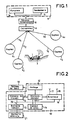
- each vehicle bearing the reference 1 in FIG. 1 is equipped with a distress beacon 2. It also has sensors 3 enabling it to establish an electrical or mechanical contact following a significant shock suffered by the vehicle and for which it is assumed that the occupants of the vehicle are injured.
- the contact established by each sensor 3 allows the distress beacon 2 to start transmitting on a specified radio frequency.
- a ground infrastructure composed in FIG. 1 of direction finders referenced from 41 to 4 n makes it possible to receive and detect this radioelectric emission.
- Each sensor 41 to 4n has a goniometer coupled to a specific computer, not shown, which can be recognized in a known manner from a map recovery of the received signal.
- a computer link 51 ... 5 n connects all the sensors 41 to 4 n to a processing unit 6 which receives all the bearing information and which deduces from it the exact coordinates of the emission point.
- a connection can for example be constituted in the manner of that known and described in report 668-2 of the Study Commission No. 1 CCIR of the ITU of October 89 having as title "Automatic control and measurement of radio frequency spectrum ".
- the computer 6 placed in a listening and alert center not shown makes it possible to generate a call on the switched telephone network to an emergency center 9 which is closest to the place of the accident and to provide the calculated geographic coordinates of the position of the accident vehicle.
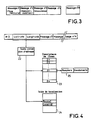
- the electronic device equipping the distress beacon 2 is shown diagrammatically in FIG. 2 inside a closed line in dotted lines 10. It comprises connected to a microprocessor 11, a clock 12, a memory 13, a shock sensor 14 , a buffer battery 15 and a radio transmitter 16 coupled to at least two antennas 17 and 18 located above and below the vehicle 1 to allow continuity of emissions from the beacon even in the event of the vehicle overturning or overturning.
- the microprocessor 11 is connected to the dashboard 19 of the vehicle.
- a switch 20 is placed on the beacon to allow the power supply to the device of FIG. 2 to be cut by the buffer battery 15.
- the buffer battery 15 is also supplied by the vehicle battery 21.
- the transmitter 16 can transmit on two different frequencies which can each have a particular meaning to allow to move on the site of the accident vehicle appropriate emergency, such as firefighters, staff of hospital services and teams of mechanical breakdown assistance for vehicle removal.
- the types of messages which are transmitted are messages which provide information on the type of vehicle involved, on its registration, on its insurance, possibly on the dealer's garage, etc. Possibly a test message can be provided to allow the test correct operation of the beacon, without triggering the emergency services.
- the frequencies and the messages transmitted on these channels are detected by the goniometers 41 to 4 n and the angles of arrival of these frequencies are transmitted with the corresponding messages to the computer 6 which performs the location of the vehicle 1.
- This location is determined in known manner in latitude and longitude with respect to the Greenwich meridian, for example, which makes it possible, in the manner shown in FIG. 4, to define using a conversion table 22 the geographic area in which the accident vehicle is located.
- the conversion table calculates a zone address in a zone descriptor table stored in a memory of the computer 6 and an address for addressing a location table.
- the zone z i pointed to by the address conversion table 22 contains, as shown at 25 in FIG. 4, all of the information necessary for the dispatch of the emergency means at the scene of the accident. This information can be compiled as shown in Figure 4, by the telephone numbers of the fire departments or gendarmeries closest to the place where the accident took place.
- the address conversion table 22 also points into the location table 24 the locality of the place closest to the accident, the route on which it occurred. The computer 6 can thus deduce the number of kilometers which separates the place of the accident from the locality.
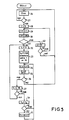
- a beacon The operation of a beacon is illustrated by steps 26 to 43 of the flow diagram of FIG. 5.
- steps 26 and 27 a shock is detected, a time delay of determined duration 30 seconds for example, and illustrated by steps 28 to 31 and 42, 43 is triggered by the shock sensors 14 of the beacon so as to allow the occupants of the vehicle to act on the dashboard 19 to possibly prohibit the emission of messages if it is found that the shock which caused the beacon to fire does not justify the sending of distress signals.
- step 42 the microprocessor 11 performs steps 32 to 41 which make it possible to send messages regularly inside windows to fixed duration t0 of 15 seconds for example at transmission interval of duration t1 of 1 second per example drawn randomly inside each window of duration t0, so as to avoid that two vehicles in collision and each having a beacon cannot have a simultaneous emission cycle.
- step 35 it is possible to stop the operation of the beacon by cutting the power supply of it by pressing the switch 20. If this action is not carried out in step 35 the process of transmission is continued by the execution of steps 37 to 41.
Abstract
Description
La présente invention concerne un système automatique de localisation et d'identification de véhicules en détresse.The present invention relates to an automatic system for locating and identifying vehicles in distress.
Le temps d'acheminement des secours sur les lieux des accidents de la circulation routière dépend de la rapidité avec laquelle ceux-ci sont prévenus et de la distance effective qui existe entre le lieu du sinistre et le poste de secours le plus proche.The time it takes for emergency services to reach the scene of road traffic accidents depends on the speed with which they are warned and the actual distance between the place of the accident and the nearest aid station.
Ainsi l'efficacité des sauvetages est directement liée à l'infrastructure, aux moyens humains et matériels à la disposition des sauveteurs pour couvrir un territoire, et la période qui s'écoule entre le sinistre et l'alerte est principalement liée au lieu de l'accident, à sa nature et aux témoins possibles qui peuvent prendre en charge cette alerte.Thus the effectiveness of the rescues is directly linked to the infrastructure, to the human and material resources available to the rescuers to cover a territory, and the period which elapses between the disaster and the alert is mainly linked to the location of the accident, its nature and the possible witnesses who can handle this alert.
Pour minimiser au maximum le temps qui s'écoule entre l'accident et l'alerte, le but de l'invention est de permettre la détection automatique d'accidents graves pouvant se produire dans le domaine notamment de la circulation routière sur un territoire déterminé.To minimize as much as possible the time elapsing between the accident and the alert, the aim of the invention is to allow the automatic detection of serious accidents which may occur in the field of road traffic in particular in a given territory .
A cet effet, l'invention a pour objet, un système automatique de localisation et d'identification de véhicules en détresse caractérisé en ce qu'il comprend, d'une part, un réseau de radiogoniomètres couplés à au moins un calculateur et disposés à des endroits bien déterminés de zones d'un territoire, et d'autre part un ensemble de balises de détresse radio disposées à l'intérieur de véhicules se déplaçant dans les zones du territoire et en ce que le calculateur comprend des moyens de traitement d'informations émises par les balises de détresse et des moyens de liaison pour localiser et identifier sur le territoire les balises émettant des signaux de détresse et transmettre les informations correspondantes aux services de secours les plus proches des lieux d'émission des balises.To this end, the subject of the invention is an automatic system for locating and identifying vehicles in distress, characterized in that it comprises, on the one hand, a network of direction finders coupled to at least one computer and arranged to well-defined locations of areas of a territory, and on the other hand a set of radio distress beacons arranged inside vehicles moving in areas of the territory and in that the computer comprises means for processing information emitted by the distress beacons and means of connection to locate and identify on the territory the beacons emitting distress signals and transmit the corresponding information to the emergency services closest to the places of emission of the beacons.
D'autres caractéristiques et avantages de l'invention apparaîtront ci-après dans la description qui suit faite en regard des dessins annexés qui représentent :
- La figure 1, un système de localisation et d'identification de véhicules en détresse selon l'invention.
- La figure 2 un mode de réalisation d'un dispositif électronique disposé à l'intérieur de chaque balise pour permettre l'émission de signaux de détresse.
- La figure 3 une suite de types de messages pouvant être transmis par les balises.
- La figure 4 un schéma d'adressage de descripteurs de zones.
- La figure 5 un organigramme pour illustrer un mode de programmation de la balise.
- FIG. 1, a system for locating and identifying vehicles in distress according to the invention.
- Figure 2 an embodiment of an electronic device disposed inside each beacon to allow the emission of distress signals.
- Figure 3 a series of types of messages that can be transmitted by tags.
- FIG. 4 an addressing scheme for zone descriptors.
- Figure 5 a flowchart to illustrate a programming mode of the tag.
Selon l'invention chaque véhicule portant la référence 1 sur la figure 1 est équipé d'une balise de détresse 2. Il possède par ailleurs des capteurs 3 lui permettant d'établir un contact électrique ou mécanique à la suite d'un choc important subi par le véhicule et pour lequel il est supposé que les occupants du véhicule sont blessés. Le contact établi par chaque capteur 3 permet à la balise de détresse 2 de se mettre en émission sur une fréquence radio spécifiée. Une infrastructure au sol composée sur la figure 1 de radiogoniomètres référencés de 4₁ à 4n permet de recevoir et de détecter cette émission radioélectrique. Chaque capteur 4₁ à 4n possède un goniomètre couplé à un calculateur spécifique, non représenté, qui permet de reconnaître de façon connue à partir d'une cartographie le relèvement du signal reçu.According to the invention each vehicle bearing the
Une liaison informatique 5₁ ... 5n relie tous les capteurs 4₁ à 4n à une unité de traitement 6 qui reçoit toutes les informations de relèvement et qui en déduit les coordonnées exactes du point d'émission. Une telle liaison peut par exemple être constituée à la manière de celle connue et décrite dans le rapport 668-2 de la commission d'Etude n° 1 CCIR de l'UIT d'octobre 89 ayant pour titre "Contrôle automatique et mesure du spectre des fréquences radioélectriques ". Le calculateur 6 placé dans un centre d'écoute et d'alerte non représenté permet de générer un appel sur le réseau téléphonique commuté vers un centre de secours 9 qui est le plus proche du lieu de l'accident et de fournir les coordonnées géographiques calculées de la position du véhicule accidenté.A computer link 5₁ ... 5 n connects all the
Le dispositif électronique équipant la balise de détresse 2 est représenté schématiquement sur la figure 2 à l'intérieur d'une ligne fermée en pointillés 10. Elle comprend reliés à un microprocesseur 11, une horloge 12, une mémoire 13, un capteur de chocs 14, une batterie tampon 15 et un émetteur radioélectrique 16 couplés à au moins deux antennes 17 et 18 situées au dessus et au dessous du véhicule 1 pour permettre une continuité des émissions de la balise même en cas de renversement ou de retournement du véhicule. Le microprocesseur 11 est relié au tableau de bord 19 du véhicule. Un interrupteur 20 est placé sur la balise pour permettre la coupure d'alimentation du dispositif de la figure 2 par la batterie tampon 15. La batterie tampon 15 est d'autre part alimentée par la batterie du véhicule 21. Suivant un premier mode de réalisation de l'invention, l'émetteur 16 peut émettre sur deux fréquences différentes qui peuvent avoir chacune une signification particulière pour permettre de déplacer sur le site du véhicule accidenté les secours appropriés, tels que les pompiers, les personnels des services hospitaliers et les équipes de dépannage mécanique pour l'enlèvement du véhicule. Les types de messages qui sont transmis sont des messages qui renseignent sur le type de véhicule accidenté, sur son immatriculation, sur son assurance, sur éventuellement le garage du concessionnaire, ... Eventuellement il peut être prévu un message de test pour permettre le test du bon fonctionnement de la balise, sans pour autant déclencher les secours. Les fréquences et les messages transmis sur ces canaux sont détectés par les goniomètres 4₁ à 4n et les angles d'arrivée de ces fréquences sont transmis avec les messages correspondants à destination du calculateur 6 qui effectue la localisation du véhicule 1. Cette localisation est déterminée de façon connue en latitude et longitude par rapport au méridien de Greenwich, par exemple, qui permet de la manière représentée à la figure 4 de définir à l'aide d'une table de conversion 22 la zone géographique dans laquelle se situe le véhicule accidenté. Pour se faire la table de conversion calcule une adresse de zone dans une table de descripteur de zones mémorisée dans une mémoire du calculateur 6 et une adresse pour adresser une table de localisation. La zone zi pointée par la table de conversion d'adresses 22 contient de la façon représentée en 25 sur la figure 4 l'ensemble des informations nécessaires au diligencement des moyens de secours sur le lieu de l'accident. Ces informations peuvent être constituées comme représentées à la figure 4, par les numéros de téléphone des services des pompiers ou de gendarmeries les plus proches du lieu auquel a eu lieu l'accident. La table de conversion d'adresses 22 pointe également dans la table de localisation 24 la localité du lieu le plus proche de l'accident, la route sur laquelle il s'est produit. Le calculateur 6 peut ainsi en déduire le nombre de kilomètres qui sépare le lieu de l'accident de la localité.The electronic device equipping the distress beacon 2 is shown diagrammatically in FIG. 2 inside a closed line in
Le fonctionnement d'une balise est illustré par les étapes 26 à 43 de l'organigramme de la figure 5. Sur cet organigramme lorsqu'aux étapes 26 et 27 un choc est détecté, une temporisation de durée déterminée 30 secondes par exemple, et illustrée par les étapes 28 à 31 et 42, 43 est déclenchée par les capteurs de chocs 14 de la balise de façon à permettre aux occupants du véhicule d'agir sur le tableau de bord 19 pour éventuellement interdire les émissions des messages s'il est constaté que le choc qui a provoqué le déclenchement de la balise ne justifie pas l'envoi de signaux de détresse. Si à l'étape 42 l'arrêt du fonctionnement de la balise n'est pas réalisé au bout des 30 secondes écoulées, le microprocesseur 11 exécute les étapes 32 à 41 qui permettent d'envoyer des messages régulièrement à l'intérieur de fenêtres à durée déterminée t₀ de 15 secondes par exemple à intervalle d'émission de durée t₁ de 1 seconde par exemple tirée aléatoirement à l'intérieur de chaque fenêtre de durée t₀, de façon à éviter que deux véhicules en collision et disposant chacun d'une balise ne puisse avoir un cycle d'émission simultané. A l'étape 35 il est possible d'arrêter le fonctionnement de la balise en coupant l'alimentation de celle-ci par action sur l'interrupteur 20. Si cette action n'est pas réalisée à l'étape 35 le processus d'émission est continué par l'exécution des étapes 37 à 41.The operation of a beacon is illustrated by
Naturellement, selon l'invention il est aussi possible d'équiper des véhicules de secours de goniomètres adaptés à la gamme des fréquences des balises de détresse. L'intérêt de cet équipement est bien sûr de permettre d'indiquer au conducteur du véhicule de secours la direction générale à suivre pour arriver sur le lieu de l'accident. Cette solution présente un intérêt notamment dans le cas d'un véhicule accidenté de nuit en zone rurale par exemple.Naturally, according to the invention it is also possible to equip emergency vehicles with goniometers adapted to the range of frequencies of the distress beacons. The advantage of this equipment is of course to allow the driver of the emergency vehicle to be informed of the general direction to follow to arrive at the scene of the accident. This solution is of interest in particular in the case of a vehicle damaged at night in rural areas for example.
Claims (15)
Applications Claiming Priority (2)
| Application Number | Priority Date | Filing Date | Title |
|---|---|---|---|
| FR9007324 | 1990-06-13 | ||
| FR9007324A FR2663433B1 (en) | 1990-06-13 | 1990-06-13 | AUTOMATIC LOCATION AND IDENTIFICATION SYSTEM FOR VEHICLES IN DISTRESS. |
Publications (2)
| Publication Number | Publication Date |
|---|---|
| EP0461969A1 true EP0461969A1 (en) | 1991-12-18 |
| EP0461969B1 EP0461969B1 (en) | 1995-12-27 |
Family
ID=9397538
Family Applications (1)
| Application Number | Title | Priority Date | Filing Date |
|---|---|---|---|
| EP91401496A Expired - Lifetime EP0461969B1 (en) | 1990-06-13 | 1991-06-07 | Automatic location and identification system for vehicles in distress |
Country Status (3)
| Country | Link |
|---|---|
| EP (1) | EP0461969B1 (en) |
| DE (1) | DE69115759T2 (en) |
| FR (1) | FR2663433B1 (en) |
Cited By (3)
| Publication number | Priority date | Publication date | Assignee | Title |
|---|---|---|---|---|
| DE4240284A1 (en) * | 1992-12-01 | 1994-06-16 | Joerg Richter | Locating stolen cars and deterring thieves - having radio telephone transmitter=receiver unit concealed in vehicle and activated by call after vehicle is stolen |
| ES2058032A2 (en) * | 1993-04-05 | 1994-10-16 | Diez De Rivera Joaquin Drake | Integral system for location, tracking and control of moving objects |
| FR2731289A1 (en) * | 1995-03-02 | 1996-09-06 | Mandereau Eric | Personal safety improving method |
Citations (5)
| Publication number | Priority date | Publication date | Assignee | Title |
|---|---|---|---|---|
| FR2203118A4 (en) * | 1971-03-26 | 1974-05-10 | Boutier Noel | |
| DE2757294A1 (en) * | 1977-08-26 | 1979-06-28 | Licentia Gmbh | Direction finding system with automatic stations and common evaluator - forms pulse duration and pause duration distributions at each station for on=off keyed transmissions |
| US4596988A (en) * | 1983-06-10 | 1986-06-24 | Wanka James T | Remote controlled tracking transmitter and tracking support system |
| GB2207787A (en) * | 1987-08-06 | 1989-02-08 | James Terence Barker | Retrieval of lost road vehicles and other articles |
| DE3830301A1 (en) * | 1988-09-07 | 1990-03-08 | Licentia Gmbh | Arrangement for identifying a road traffic accident which occurs in a predetermined area |
Family Cites Families (1)
| Publication number | Priority date | Publication date | Assignee | Title |
|---|---|---|---|---|
| DE2641282C2 (en) * | 1976-09-14 | 1983-01-27 | Licentia Patent-Verwaltungs-Gmbh, 6000 Frankfurt | Arrangement for recognizing a traffic emergency occurring in a given area |
-
1990
- 1990-06-13 FR FR9007324A patent/FR2663433B1/en not_active Expired - Fee Related
-
1991
- 1991-06-07 EP EP91401496A patent/EP0461969B1/en not_active Expired - Lifetime
- 1991-06-07 DE DE1991615759 patent/DE69115759T2/en not_active Expired - Fee Related
Patent Citations (5)
| Publication number | Priority date | Publication date | Assignee | Title |
|---|---|---|---|---|
| FR2203118A4 (en) * | 1971-03-26 | 1974-05-10 | Boutier Noel | |
| DE2757294A1 (en) * | 1977-08-26 | 1979-06-28 | Licentia Gmbh | Direction finding system with automatic stations and common evaluator - forms pulse duration and pause duration distributions at each station for on=off keyed transmissions |
| US4596988A (en) * | 1983-06-10 | 1986-06-24 | Wanka James T | Remote controlled tracking transmitter and tracking support system |
| GB2207787A (en) * | 1987-08-06 | 1989-02-08 | James Terence Barker | Retrieval of lost road vehicles and other articles |
| DE3830301A1 (en) * | 1988-09-07 | 1990-03-08 | Licentia Gmbh | Arrangement for identifying a road traffic accident which occurs in a predetermined area |
Cited By (3)
| Publication number | Priority date | Publication date | Assignee | Title |
|---|---|---|---|---|
| DE4240284A1 (en) * | 1992-12-01 | 1994-06-16 | Joerg Richter | Locating stolen cars and deterring thieves - having radio telephone transmitter=receiver unit concealed in vehicle and activated by call after vehicle is stolen |
| ES2058032A2 (en) * | 1993-04-05 | 1994-10-16 | Diez De Rivera Joaquin Drake | Integral system for location, tracking and control of moving objects |
| FR2731289A1 (en) * | 1995-03-02 | 1996-09-06 | Mandereau Eric | Personal safety improving method |
Also Published As
| Publication number | Publication date |
|---|---|
| EP0461969B1 (en) | 1995-12-27 |
| DE69115759T2 (en) | 1996-05-15 |
| DE69115759D1 (en) | 1996-02-08 |
| FR2663433A1 (en) | 1991-12-20 |
| FR2663433B1 (en) | 1993-04-23 |
Similar Documents
| Publication | Publication Date | Title |
|---|---|---|
| US5389935A (en) | Automatic system for locating and identifying vehicles in distress | |
| US8193949B2 (en) | Alert and warning system and method | |
| US9254781B2 (en) | Emergency vehicle warning device and system | |
| US9558663B2 (en) | Animal detecting and notification method and system | |
| US6580367B2 (en) | Vehicle information dispatch system | |
| EP2517040B1 (en) | System for tracking ships at sea | |
| US20060261979A1 (en) | Event detection system | |
| US20030141990A1 (en) | Method and system for communicating alert information to a vehicle | |
| US20050037730A1 (en) | Mobile wireless phone with impact sensor, detects vehicle accidents/thefts, transmits medical exigency-automatically notifies authorities | |
| FR2682792A1 (en) | Device intended to avoid multiple pile-ups | |
| MXPA03004888A (en) | Locomotive wireless video recorder and recording system. | |
| US20040155795A1 (en) | Systems and methods for motor vehicle-based emergency/hazard detection | |
| CN106023649A (en) | Pedestrian red light running caution system based on WAVE communication and method | |
| CN108682185A (en) | A kind of accident alarming method and system | |
| US6539307B1 (en) | System and method for monitoring interaction between objects and multiple mobile units | |
| EP0461969B1 (en) | Automatic location and identification system for vehicles in distress | |
| JP4077171B2 (en) | Illumination lamp operation information collection method and illumination lamp operation information collection system | |
| EP0407300B1 (en) | On board electronic anti-collision device for a vehicle | |
| CA2045050A1 (en) | Automatic positioning and identification system of distress vehicles | |
| JPH036929A (en) | Traveling object location monitor system and its apparatus | |
| JPH10221090A (en) | Emergency treatment apparatus for vehicle | |
| FR2637105A1 (en) | Device for preventing road accidents | |
| JP2002063672A (en) | Vehicle traveling track display system | |
| EP0489661A1 (en) | Method of transmitting information by radio waves between a satellite and a plurality of ground stations, and arrangements for the implementation of the system | |
| JP3605320B2 (en) | Car accident support system |
Legal Events
| Date | Code | Title | Description |
|---|---|---|---|
| PUAI | Public reference made under article 153(3) epc to a published international application that has entered the european phase |
Free format text: ORIGINAL CODE: 0009012 |
|
| AK | Designated contracting states |
Kind code of ref document: A1 Designated state(s): BE DE ES FR GB IT |
|
| 17P | Request for examination filed |
Effective date: 19920526 |
|
| RAP1 | Party data changed (applicant data changed or rights of an application transferred) |
Owner name: THOMSON-CSF |
|
| 17Q | First examination report despatched |
Effective date: 19940204 |
|
| GRAA | (expected) grant |
Free format text: ORIGINAL CODE: 0009210 |
|
| AK | Designated contracting states |
Kind code of ref document: B1 Designated state(s): BE DE ES FR GB IT |
|
| PG25 | Lapsed in a contracting state [announced via postgrant information from national office to epo] |
Ref country code: IT Free format text: LAPSE BECAUSE OF FAILURE TO SUBMIT A TRANSLATION OF THE DESCRIPTION OR TO PAY THE FEE WITHIN THE PRE;WARNING: LAPSES OF ITALIAN PATENTS WITH EFFECTIVE DATE BEFORE 2007 MAY HAVE OCCURRED AT ANY TIME BEFORE 2007. THE CORRECT EFFECTIVE DATE MAY BE DIFFERENT FROM THE ONE RECORDED.SCRIBED TIME-LIMIT Effective date: 19951227 Ref country code: ES Free format text: THE PATENT HAS BEEN ANNULLED BY A DECISION OF A NATIONAL AUTHORITY Effective date: 19951227 |
|
| REF | Corresponds to: |
Ref document number: 69115759 Country of ref document: DE Date of ref document: 19960208 |
|
| GBT | Gb: translation of ep patent filed (gb section 77(6)(a)/1977) |
Effective date: 19960217 |
|
| PG25 | Lapsed in a contracting state [announced via postgrant information from national office to epo] |
Ref country code: GB Effective date: 19960607 |
|
| PG25 | Lapsed in a contracting state [announced via postgrant information from national office to epo] |
Ref country code: BE Effective date: 19960630 |
|
| PLBE | No opposition filed within time limit |
Free format text: ORIGINAL CODE: 0009261 |
|
| STAA | Information on the status of an ep patent application or granted ep patent |
Free format text: STATUS: NO OPPOSITION FILED WITHIN TIME LIMIT |
|
| 26N | No opposition filed | ||
| BERE | Be: lapsed |
Owner name: THOMSON-CSF Effective date: 19960630 |
|
| GBPC | Gb: european patent ceased through non-payment of renewal fee |
Effective date: 19960607 |
|
| PG25 | Lapsed in a contracting state [announced via postgrant information from national office to epo] |
Ref country code: FR Effective date: 19970228 |
|
| PG25 | Lapsed in a contracting state [announced via postgrant information from national office to epo] |
Ref country code: DE Effective date: 19970301 |
|
| REG | Reference to a national code |
Ref country code: FR Ref legal event code: ST |