EP0461480A2 - Method and apparatus for control of engine fuel injection - Google Patents
Method and apparatus for control of engine fuel injection Download PDFInfo
- Publication number
- EP0461480A2 EP0461480A2 EP91108849A EP91108849A EP0461480A2 EP 0461480 A2 EP0461480 A2 EP 0461480A2 EP 91108849 A EP91108849 A EP 91108849A EP 91108849 A EP91108849 A EP 91108849A EP 0461480 A2 EP0461480 A2 EP 0461480A2
- Authority
- EP
- European Patent Office
- Prior art keywords
- engine
- fuel
- flow rate
- air mass
- acceleration
- Prior art date
- Legal status (The legal status is an assumption and is not a legal conclusion. Google has not performed a legal analysis and makes no representation as to the accuracy of the status listed.)
- Granted
Links
Images


Classifications
-
- F—MECHANICAL ENGINEERING; LIGHTING; HEATING; WEAPONS; BLASTING
- F02—COMBUSTION ENGINES; HOT-GAS OR COMBUSTION-PRODUCT ENGINE PLANTS
- F02D—CONTROLLING COMBUSTION ENGINES
- F02D41/00—Electrical control of supply of combustible mixture or its constituents
- F02D41/02—Circuit arrangements for generating control signals
- F02D41/18—Circuit arrangements for generating control signals by measuring intake air flow
-
- F—MECHANICAL ENGINEERING; LIGHTING; HEATING; WEAPONS; BLASTING
- F02—COMBUSTION ENGINES; HOT-GAS OR COMBUSTION-PRODUCT ENGINE PLANTS
- F02D—CONTROLLING COMBUSTION ENGINES
- F02D41/00—Electrical control of supply of combustible mixture or its constituents
- F02D41/02—Circuit arrangements for generating control signals
- F02D41/04—Introducing corrections for particular operating conditions
- F02D41/045—Detection of accelerating or decelerating state
-
- F—MECHANICAL ENGINEERING; LIGHTING; HEATING; WEAPONS; BLASTING
- F02—COMBUSTION ENGINES; HOT-GAS OR COMBUSTION-PRODUCT ENGINE PLANTS
- F02D—CONTROLLING COMBUSTION ENGINES
- F02D41/00—Electrical control of supply of combustible mixture or its constituents
- F02D41/02—Circuit arrangements for generating control signals
- F02D41/04—Introducing corrections for particular operating conditions
- F02D41/047—Taking into account fuel evaporation or wall wetting
-
- F—MECHANICAL ENGINEERING; LIGHTING; HEATING; WEAPONS; BLASTING
- F02—COMBUSTION ENGINES; HOT-GAS OR COMBUSTION-PRODUCT ENGINE PLANTS
- F02D—CONTROLLING COMBUSTION ENGINES
- F02D41/00—Electrical control of supply of combustible mixture or its constituents
- F02D41/02—Circuit arrangements for generating control signals
- F02D41/04—Introducing corrections for particular operating conditions
- F02D41/10—Introducing corrections for particular operating conditions for acceleration
- F02D41/105—Introducing corrections for particular operating conditions for acceleration using asynchronous injection
Definitions
- the present invention relates to a method of controlling engine fuel injection, and is particularly concerned with a method and apparatus for asynchronous injection in an electronic controller of an automobile engine.
- An electronic controller of an automobile engine controls the quantity of a gasoline injection in accordance with the air mass which flows into the engine in response to the angle of the accelerator pedal so as to obtain a theoretical air fuel ratio. In other words, it obtains the air mass flow rate of the air flowing into the cylinder, uses an electric circuit such as a microprocessor to obtain a required fuel quantity and then controls the quantity of fuel injection.
- an asynchronous injection is performed by using a compensation coefficient obtained by table lookup whose parameter is the throttle opening angle variation, as described on pages 116 to 117 of "Electronic Controlled Gasoline Injection," Sankaido, May 5, 1987.
- a primary object of the present invention is, therefore, to provide an engine fuel injection control method and apparatus for determining a proper air fuel ratio in every drive mode without using a table whose data would have to be obtained by trial and error, so as to eliminate the above-mentioned disadvantages.
- a method and apparatus are characterized in that in engine control by controlling the quantity of a fuel supply to a cylinder according to the air mass flowing into the cylinder, the state of the acceleration of the engine is detected and also it is judged whether or not the engine is in a specific acceleration state, that, when the engine is judged to be in a specific state of acceleration, the air mass flow rate of the air flowing into a specific cylinder having undergone a fuel injection is predicted, that the predicted air mass flow rate is used for determining a proper asynchronous fuel injection quantity for the above-mentioned acceleration state for the above-mentioned specific cylinder, and then that the determined quantity of fuel is injected asynchronously into the above-mentioned specific cylinder.
- asynchronous fuel injection quantity may be determined according to a crank angle detected in advance.
- the above-mentioned asynchronous fuel injection quantity is determined so that it can be a supplemental fuel supply quantity necessary for achieving a proper air fuel ratio for the above-mentioned predicted air mass flow rate.
- the above-mentioned specific cylinder is a cylinder having the latest fuel injection. It is desirable that an asynchronous injection quantity should be determined by fuel supply quantity calculation with regard to the difference between the predicted air mass flow rate of the air flowing into the cylinder having the latest fuel injection and the air mass flow rate used for calculating the fuel supply quantity so that a desired air fuel ratio can be achieved.
- Fig. 1 is a flowchart of an engine fuel injection control method which embodies the present invention
- Fig. 2 is a block diagram of an engine fuel injection control apparatus for carrying out an engine fuel injection control method which embodies the present invention
- Fig. 3 is an explanatory representation concerning the necessity of asynchronous injection in an engine
- Figs. 4 and 5 are illustrations of the timing of air mass flow rate calculation, fuel injection and an induction stroke in relation to the angle of an engine crank
- Fig. 6 is a view of the course of fuel in an intake manifold
- Fig. 7 is a flow diagram of the calculation processes in an engine fuel injection control method which embodies the present invention.
- FIG. 1 and 2 of the drawing there are shown a flowchart of an engine fuel injection control method which embodies the present invention and a block diagram of a fuel injection control apparatus for carrying out the method of Fig. 1 in a multi-point fuel injection engine respectively.
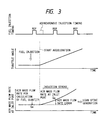
- Fig. 3 is graphs illustrating the timing of fuel injections, the angle of the throttle and the responding air mass flow rate at the inlet port during the acceleration of a vehicle. They show how fuel is injected by the input of the timing signal REF for timing a synchronous injection and causes acceleration immediately after that.
- Ordinary engines have a fuel injection (synchronous injection) one stroke before their induction stroke. Thus, their fuel injection time is shown to be to the left of the induction stroke in Fig. 3.
- Qa represents the air mass flow rate used for calculation of synchronous fuel injection quantity.
- the air mass flow rate Q ⁇ a at inlet port in the induction stroke when fuel will be flowing into the cylinder the mass flow rate of the air actually drawn into the cylinder is much greater than the air mass flow rate used for calculating the quantity of the synchronous injection quantity.
- the air mass flow rate error ⁇ Qa becomes larger along with the lean spike.
- an air mass flow rate error depends on the time of acceleration in relation to that of an induction stroke and the responding air mass flow rate at the inlet port, namely the responding change of the air mass flow rate at the inlet port for a unit of time. Therefore, an asynchronous fuel injection quantity must be determined in compliance with the time of acceleration in relation to an induction stroke and with the air mass flow rate at the inlet port. Otherwise, proper control of fuel injection is impossible.
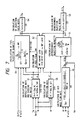
- a control unit 3 is composed of a CPU 4, ROM 5, RAM 6, timer 7, an I/O LSI 8 and a bus for connecting them electrically.
- the information resulting from the detection by a throttle angle sensor 10, an air flow sensor 9, a water temperature sensor 13, a crank angle sensor 14 and an oxygen sensor 12 is sent to the RAM 6 through the I/O LSI 8 installed in the control unit 3.
- the I/O LSI 8 issues an injection valve drive signal to an injector 11.
- the timer 8 sends an interruption request to the CPU 4 at a certain interval.
- the CPU 4 executes a control program, which is stored in the ROM 5, for performing the processes which will be described in detail below.
- the reference numeral 1 denotes a cylinder, 2 a crank, 15 an intake manifold, 16 an exhaust manifold, 17 an intake valve, and 18 an exhaust valve.
- the control unit obtains information from the air flow sensor 9, throttle angle sensor 10, crank angle sensor 14 and water temperature sensor 13.
- the unit stores values which are output from the throttle angle sensor 10 till after 20 msec in order to use the values for the judgment of acceleration at the next step 102.
- the unit also calculates in a specific manner the air mass flow rate at the inlet port after one stroke or the present air mass flow rate at the inlet port by using information obtained by the measurement by these sensors.
- the unit also stores values of the air mass flow rate till after a specific length of time in order to use the values for the calculation at step 105.
- acceleration is judged. How this process is performed will be described from now.
- the state of acceleration can be detected most swiftly by using the angle of the opening of the throttle. Therefore, it is judged that, when the change of the throttle opening angle within a specific length of time exceeds a specific value, the engine goes into the state of acceleration. For instance, it is judged that the engine goes into acceleration when the following equation is satisfied, the current time being i: ⁇ th(i) - ⁇ th(i - 2) > k1 (1) where ⁇ th(i) is a sample of the throttle opening angle at time i (the sampling period is 10 ms), and k1 is a positive constant.
- control unit 3 When the engine is judged to be in the state of acceleration, the control unit 3 performs the processes at steps 104 to 109 for asynchronous injection and the calculation processes at steps 110 to 113 for synchronous injection. When the engine is judged to be not in the state of acceleration, only the calculation processes at steps 110 to 113 for synchronous injection are performed.
- the rate ratio x' for the deposition of asynchro properly injected fuel on the intake manifold wall is calculated by using the information obtained by the measurement at step 101.
- the method of calculating the rate ratio x' will be described later in detail.
- step 104 it is judged which cylinder has the latest synchronous injection.
- Step 105 is for predicting and calculating the air mass flow rate Q ⁇ a of the air flowing into the cylinder judged at step 104 to have the latest synchronous injection.
- the unit 3 stores a rate Q ⁇ a for each cylinder by using a program which will be described later.
- an asynchronous fuel injection quantity ⁇ G f is calculated by using the above-mentioned air mass error ⁇ Qa and the rate x' for the deposition of asynchronously injected fuel on the intake manifold wall, as described later.
- asynchronous fuel injection quantity ⁇ G f is converted into an asynchronous injection pulse width ⁇ Ti by using the following equation (2) in order to perform an asynchronous injection.
- ⁇ Ti K ⁇ ⁇ G f + Ts (2) where Ts is an idle injection period.
- Step 109 is for using the following equation (3) to update the fuel film quantity M f for the cylinder judged to have the latest synchronous injection at step 104: M f ⁇ M f + x' ⁇ ⁇ G f (3)
- This update equation expresses the increase of the fuel film quantity by x' ⁇ G f due to the asynchronous injection.
- the update of a fuel film quantity by synchronous injection is performed by another program.
- a synchronous injection quantity is calculated.
- Step 110 is, as described later, for calculating the rate x of the deposition of injected fuel on the intake manifold wall and the ratio ⁇ of the sucking off of a fuel film by a cylinder during an induction stroke.
- step 111 it is judged in which cylinder the next synchronous injection is performed.
- control unit 3 The processes performed by the control unit 3 are thus completed, and the unit 3 waits for the next interruption request.
- Fig. 1b is a flowchart of the update of a fuel film quantity by the program referred to in the description of the above-mentioned step 108. This program is executed immediately after a synchronous injection is performed.
- Step 114 is for judging in which cylinder the latest synchronous injection is performed.
- the fuel film quantity for a cylinder judged to have the latest synchronous injection is updated by using the following equation (5): M f ⁇ M f + (x ⁇ G f - ⁇ ⁇ M f ) (5) where x, ⁇ , G f and M f are latest values.
- Step 116 is for storing the latest air mass flow rate Qa used for calculating a synchronous fuel injection quantity G f in order to use the information to calculate the air mass error ⁇ Qa at the above-mentioned step 106 shown in Fig. 1a.
- a first method will be described for predicting the air mass flow rate Q ⁇ a which has the latest synchronous injection after acceleration is detected at step 103.
- the angle of the crank is used.
- Fig. 4 is an illustration of the timing of air mass flow rate calculation, fuel injection and an induction stroke in relation to the angle of the crank.
- the air mass flow rate Q ⁇ a is represented by the air mass which flows into the cylinder when the crank is in the middle of an induction stroke.
- the air mass flow rate Q ⁇ a which is assumed to change linearly with time, is given by the following equation, the number of the revolutions and the crank angle between the position of crank in the time i and the position of the crank in the middle of an induction stroke being N (rpm) and ⁇ (deg) respectively:
- ⁇ for predicting Q ⁇ a means that the prediction is performed indirectly by using the time of the acceleration.
- a second method for predicting the air mass flow rate Q ⁇ a is related to a throttle and speed method, namely, one of using the angle of the opening of the throttle and the number N of the revolutions in the below way.
- ⁇ th(i) is a detected throttle opening angle
- ⁇ th(i) is a predicted throttle opening angle
- ⁇ t is a throttle opening angle detection cycle
- T is the time for one stroke (time required for a half revolution of the engine).
- Fig. 5 is an illustration of the timing of air mass calculation, fuel injection and an induction stroke in relation to the angle of the crank.
- i - 2, i - 1 and i each are the time for calculating the air mass flow rate at the inlet port
- ⁇ t is the cycle of the calculation of the air mass
- N is the number of revolutions
- ⁇ is the crank angle between the time i and the position of the crank in the middle of an induction stroke
- Qa'(i) can be considered to be a value after one stroke since the angle of the throttle has already changed. This value represents the air mass flow rate at the inlet port with the crank in the position for it in Fig. 5.
- Qa'(i - 2) represents the value of the air mass flow rate at the inlet port at the time i - 2, namely, when the crank is in the position for it in the illustration.
- the air mass flow rate Q ⁇ a with the crank positioned in the middle of an induction stroke is assuming that the air mass flow rate changes linearly with respect to time, given by the following proportional distribution equation using Qa'(i) and Qa'(i - 2): where it is assumed that in the middle of an induction stroke the crank is positioned a crank angle of 90 degrees after the top dead center (TDC), that fuel injection time is a crank angle of 90 degrees before the TDC and that fuel injection time REF and the time for calculating Qa (i - 2) used for calulating the fuel injection quantity almost coincide with each other.
- TDC top dead center
- This method is a throttle and speed method and also is, in the system for calculating the air mass flow rate Qa(i) in a specific cycle, to predict the air mass flow rate Qa'(i) after one stroke by using the following equation (9) and then to calculate Q ⁇ a by using the equation (8):
- Qa' (i) Qa ( i ) + T ⁇ t ⁇ Qa(i)-Qa(i-1) ⁇ (9) where ⁇ t is the cycle of the calculation of the air mass flow rate, and T is the time for one stroke.
- the fuel shortage G f0 is given by the following equation (9), the objective air fuel ratio being (A/F)0:
- G f ⁇ e (1-x) ⁇ G f ⁇ + ⁇ ⁇ M f ⁇ old (11)
- M f ⁇ new M f ⁇ old + ( x ⁇ G f - ⁇ ⁇ M fold ) (12)
- G fe is the quantity (g) of the fuel coming into the cylinder
- G f is a synchronous fuel injection quantity (g)
- M fold is the fuel film quantity (g) before fuel injection
- M fnew is the fuel film quantity (g) at the end of an induction stroke after fuel injection
- x is the rate of the deposition of injected fuel on the intake manifold wall
- ⁇ is the ratio of the sucking off of a fuel film by the cylinder during an induction stroke.
- Fig. 6 is a view of a cylinder and the intake manifold of an engine for explaining how the equations (11) and (12) work.
- the equation (11) expresses the flow into the cylinder 1 of the fuel (1 - x) G f not deposited on the intake manifold wall which are part of the fuel G f injected by an injector 11 and the fuel ⁇ M fold whose port is sucked off by the cylinder.
- the equation (12) expresses the increase of the quantity of fuel film from M fold by x ⁇ G f due to fuel injection and its decrease into M fnew by ⁇ M fold during an induction stroke.
- a desired air fuel ratio (A/F)0 can be achieved by satisfying the following equation:
- a desired air fuel ratio can be achieved by satisfying the following equation (19):
- the reason why x' has a crank angle is that asynchronous injection is not so constant in respect of injection timing as synchronous injection with the result that there is a difference between them in fuel deposition condition.
- the injection quanti ty M f is updated by using the equation (14) so that a latest value can be used for determining a synchronous injection quantity.
- fuel is controlled by determining a fuel film quantity for each cylinder.
- Fig. 7 illustrates the calculation processes for the fuel control by synchronous and asynchronous injection for a cylinder of such a multi-point fuel injection engine.
- the parenthesised numbers attached to the blocks in the illustration are those of the equations so far used for description.
- Block 51 is for calculating the deposition rate x and the sucking-off ratio by using the calculated air mass flow rate Qa'(i) at the inlet port after one stroke, the number N of engine revolutions, the water temperature Tw.
- the fuel film quantity M f is updated by using the fuel deposition rates x and x' and the sucking-off ratio ⁇ , the synchronous injection quantity G f and the asynchronous injection quantity ⁇ G.
- the fuel film quantity M f is updated every time fuel injection is completed. This update is performed every cycle.
- the quantity of an injection is calculated by using the fuel deposition rate x, the sucking-off ratio ⁇ , the latest fuel film quantity M f , the number N of revolutions and the air mass flow rate Qa'(i) at the inlet port after one stroke.
- Block 54 is for calculating the synchronous injection pulse width Ti by using the injection quantity G f .
- k is a constant
- Ts is an idle injection period.
- the calculation in blocks 51 and 53 is performed at a specific interval only when the cylinder subject to the fuel control system is a cylinder where the next injection is carried out.
- fuel is injected with the latest synchronous injection pulse width Ti.
- Blocks 55 to 58 work when the engine changes from the stationary driving status into the acceleration status when though the cylinder subject to the system has undergone a synchronous injection no synchronous injection is yet applied to any other cylinders.
- the air mass flow rate Q ⁇ a during an induction stroke of the subject cylinder is calculated by using Qa'(i), ⁇ and the number N of revolutions (by the throttle and speed method for detecting the air mass flow rate which has been described as the third method for step 105 shown in Fig. 1).
- the fuel deposition rate x' is calculated by using the calculated air mass flow rate Qa'(i) at the inlet port after one stroke, the number N of engine revolutions, the crank angle ⁇ between the time and the position of the crank in the middle of an induction stroke.
- the asynchronous injection pulse width ⁇ Ti is calculated by using the air mass error ⁇ Qa, the number N of revolutions, the fuel deposition rate x' and the asynchronous injection quantity ⁇ G f . Immediately after the calculation of ⁇ Ti, asynchronous injection is performed.
- asynchronous fuel injection quantity can be determined without using a table whose matching would be required for each engine model, so the processes of developing an engine fuel injector can be decreased in number.
- the shortage of fuel occurring with the synchronous injection at the early stage of acceleration is determined logically in compliance with the time of acceleration so as to provide a proper quantity of asyn chronously injected fuel in various drive modes to make up for the shortage. This allows air fuel ratio control to be more accurate.
Abstract
Description
- The present invention relates to a method of controlling engine fuel injection, and is particularly concerned with a method and apparatus for asynchronous injection in an electronic controller of an automobile engine.
- An electronic controller of an automobile engine controls the quantity of a gasoline injection in accordance with the air mass which flows into the engine in response to the angle of the accelerator pedal so as to obtain a theoretical air fuel ratio. In other words, it obtains the air mass flow rate of the air flowing into the cylinder, uses an electric circuit such as a microprocessor to obtain a required fuel quantity and then controls the quantity of fuel injection. In the fuel injection control by conventional electronic engine controllers, especially in their fuel injection control during the acceleration of the automobile, to make up for the shortage of fuel occurring with a synchronous injection during acceleration, an asynchronous injection is performed by using a compensation coefficient obtained by table lookup whose parameter is the throttle opening angle variation, as described on
pages 116 to 117 of "Electronic Controlled Gasoline Injection," Sankaido, May 5, 1987. - According to the technique shown in the above-mentioned text, for every engine model a table must be produced by the trial-and-error finding of table data with throttle opening angle variations being parameters. Therefore, such a technique has the disadvantage that a large number of processes are needed for producing the table.
- But in the first place, the shortage of fuel to be made up for by an asynchronous injection should be specified as a value equivalent to the difference between the air mass flow rate of the air actually drawn into the engine and the air mass flow rate of the air used for calculating the synchronous injection. For this purpose, it is necessary to directly or indirectly use the time of acceleration and the responding air mass flow rate at the inlet port during the early stage of acceleration. However, conventionally no attention has been paid to the time of acceleration in relation to an induction stroke, and the quantity of asynchronous induction has been calculated in most cases by using only an opening angle variation, with the result that excessive or insufficient asynchronous injections still occur with the shifty time of acceleration. Therefore, prior art attempts have the disadvantage that it is impossible to determine a proper asynchronous injection quantity for achieving a desired air fuel ratio in various drive modes.
- A primary object of the present invention is, therefore, to provide an engine fuel injection control method and apparatus for determining a proper air fuel ratio in every drive mode without using a table whose data would have to be obtained by trial and error, so as to eliminate the above-mentioned disadvantages.
- To achieve this object, a method and apparatus according to the present invention are characterized in that in engine control by controlling the quantity of a fuel supply to a cylinder according to the air mass flowing into the cylinder, the state of the acceleration of the engine is detected and also it is judged whether or not the engine is in a specific acceleration state, that, when the engine is judged to be in a specific state of acceleration, the air mass flow rate of the air flowing into a specific cylinder having undergone a fuel injection is predicted, that the predicted air mass flow rate is used for determining a proper asynchronous fuel injection quantity for the above-mentioned acceleration state for the above-mentioned specific cylinder, and then that the determined quantity of fuel is injected asynchronously into the above-mentioned specific cylinder.
- Note that the above-mentioned proper asynchronous fuel injection quantity may be determined according to a crank angle detected in advance.
- In a preferred embodiment of the above-mentioned method and apparatus, the above-mentioned asynchronous fuel injection quantity is determined so that it can be a supplemental fuel supply quantity necessary for achieving a proper air fuel ratio for the above-mentioned predicted air mass flow rate. Note that the above-mentioned specific cylinder is a cylinder having the latest fuel injection. It is desirable that an asynchronous injection quantity should be determined by fuel supply quantity calculation with regard to the difference between the predicted air mass flow rate of the air flowing into the cylinder having the latest fuel injection and the air mass flow rate used for calculating the fuel supply quantity so that a desired air fuel ratio can be achieved.
- Concerning the characteristic effects of the present invention, it is possible to judge acceleration to calculate the shortage of fuel occurring to a cylinder with the synchronous injection at the early stage of acceleration by using a predicted air mass flow rate, the time of acceleration and other various variables. Therefore, a proper supplemental fuel supply quantity (asynchronous injection quantity) for achieving a desired air fuel ratio in various drive modes can be determined. Besides, a proper asynchronous fuel injection quantity can be determined without using a table requiring matching, so the processes of developing a fuel injection system can be decreased in number.
- The foregoing and other objects, advantages, manner of operation and novel features of the present invention will be understood from the following detailed description when read in connection with the accompanying drawings.
- In the accompanying drawings: Fig. 1 is a flowchart of an engine fuel injection control method which embodies the present invention; Fig. 2 is a block diagram of an engine fuel injection control apparatus for carrying out an engine fuel injection control method which embodies the present invention; Fig. 3 is an explanatory representation concerning the necessity of asynchronous injection in an engine; Figs. 4 and 5 are illustrations of the timing of air mass flow rate calculation, fuel injection and an induction stroke in relation to the angle of an engine crank; Fig. 6 is a view of the course of fuel in an intake manifold; and Fig. 7 is a flow diagram of the calculation processes in an engine fuel injection control method which embodies the present invention.
- Referring now to Figs. 1 and 2 of the drawing, there are shown a flowchart of an engine fuel injection control method which embodies the present invention and a block diagram of a fuel injection control apparatus for carrying out the method of Fig. 1 in a multi-point fuel injection engine respectively.
- Before description of these embodiments, why asynchronous injection is necessary will be explained to ease the understanding of the embodiment.
- Fig. 3 is graphs illustrating the timing of fuel injections, the angle of the throttle and the responding air mass flow rate at the inlet port during the acceleration of a vehicle. They show how fuel is injected by the input of the timing signal REF for timing a synchronous injection and causes acceleration immediately after that. Ordinary engines have a fuel injection (synchronous injection) one stroke before their induction stroke. Thus, their fuel injection time is shown to be to the left of the induction stroke in Fig. 3.
- Qa represents the air mass flow rate used for calculation of synchronous fuel injection quantity. When acceleration starts immediately after a synchronous injection, the air mass flow rate Q̂a at inlet port in the induction stroke when fuel will be flowing into the cylinder the mass flow rate of the air actually drawn into the cylinder is much greater than the air mass flow rate used for calculating the quantity of the synchronous injection quantity. Fuel being supplied only with synchronous injection, such an engine lacks the quantity of fuel corresponding to this air mass flow rate error

- To compensate for a great shortage of fuel due to rapid acceleration, it is necessary to perform an asynchronous injection before an induction stroke.
- As shown in Fig. 3, an air mass flow rate error depends on the time of acceleration in relation to that of an induction stroke and the responding air mass flow rate at the inlet port, namely the responding change of the air mass flow rate at the inlet port for a unit of time. Therefore, an asynchronous fuel injection quantity must be determined in compliance with the time of acceleration in relation to an induction stroke and with the air mass flow rate at the inlet port. Otherwise, proper control of fuel injection is impossible.
- Now, the embodiments of the present invention which are shown in Figs. 1 and 2 will be described. In the apparatus for control of engine fuel injection which is shown in Fig. 2, a
control unit 3 is composed of aCPU 4, ROM 5,RAM 6,timer 7, an I/O LSI 8 and a bus for connecting them electrically. The information resulting from the detection by athrottle angle sensor 10, anair flow sensor 9, awater temperature sensor 13, acrank angle sensor 14 and anoxygen sensor 12 is sent to theRAM 6 through the I/O LSI 8 installed in thecontrol unit 3. The I/O LSI 8 issues an injection valve drive signal to aninjector 11. Thetimer 8 sends an interruption request to theCPU 4 at a certain interval. TheCPU 4 executes a control program, which is stored in the ROM 5, for performing the processes which will be described in detail below. Note that thereference numeral 1 denotes a cylinder, 2 a crank, 15 an intake manifold, 16 an exhaust manifold, 17 an intake valve, and 18 an exhaust valve. - Now, in reference to the flowchart in Fig. 1, the calculation of synchronous and asynchronous injection quantities by the above-mentioned
control unit 3 and the process of synchronous injection will be described in detail. These processes are performed in a 10 msc cycle. - First, at
step 101, the control unit obtains information from theair flow sensor 9,throttle angle sensor 10,crank angle sensor 14 andwater temperature sensor 13. The unit stores values which are output from thethrottle angle sensor 10 till after 20 msec in order to use the values for the judgment of acceleration at thenext step 102. The unit also calculates in a specific manner the air mass flow rate at the inlet port after one stroke or the present air mass flow rate at the inlet port by using information obtained by the measurement by these sensors. The unit also stores values of the air mass flow rate till after a specific length of time in order to use the values for the calculation atstep 105. - At
step 102, acceleration is judged. How this process is performed will be described from now. The state of acceleration can be detected most swiftly by using the angle of the opening of the throttle. Therefore, it is judged that, when the change of the throttle opening angle within a specific length of time exceeds a specific value, the engine goes into the state of acceleration. For instance, it is judged that the engine goes into acceleration when the following equation is satisfied, the current time being i:
where ϑth(i) is a sample of the throttle opening angle at time i (the sampling period is 10 ms), and k₁ is a positive constant. - When the engine is judged to be in the state of acceleration, the
control unit 3 performs the processes atsteps 104 to 109 for asynchronous injection and the calculation processes atsteps 110 to 113 for synchronous injection. When the engine is judged to be not in the state of acceleration, only the calculation processes atsteps 110 to 113 for synchronous injection are performed. - At
step 103, the rate ratio x' for the deposition of asynchro nously injected fuel on the intake manifold wall is calculated by using the information obtained by the measurement atstep 101. The method of calculating the rate ratio x' will be described later in detail. - At
step 104, it is judged which cylinder has the latest synchronous injection. - Step 105 is for predicting and calculating the air mass flow rate Q̂a of the air flowing into the cylinder judged at
step 104 to have the latest synchronous injection. - Step 106 is for calculating an air mass error

step 105. Theunit 3 stores a rate Q̂a for each cylinder by using a program which will be described later. - At
step 107, an asynchronous fuel injection quantity ΔGf is calculated by using the above-mentioned air mass error ΔQa and the rate x' for the deposition of asynchronously injected fuel on the intake manifold wall, as described later. - At
step 108, the above-mentioned asynchronous fuel injection quantity ΔGf is converted into an asynchronous injection pulse width ΔTi by using the following equation (2) in order to perform an asynchronous injection.

where Ts is an idle injection period. - Step 109 is for using the following equation (3) to update the fuel film quantity Mf for the cylinder judged to have the latest synchronous injection at step 104:
- This update equation expresses the increase of the fuel film quantity by x'·ΔGf due to the asynchronous injection. The update of a fuel film quantity by synchronous injection is performed by another program.
- At the
steps following step 109, a synchronous injection quantity is calculated. - Step 110 is, as described later, for calculating the rate x of the deposition of injected fuel on the intake manifold wall and the ratio α of the sucking off of a fuel film by a cylinder during an induction stroke.
- At
step 111, it is judged in which cylinder the next synchronous injection is performed. - Step 112 is for calculating a synchronous fuel injection quantity Gf by using the latest fuel film quantity Mf (= Mfold) calculated for the cylinder judged to have the next synchronous injection and by using the information obtained from the measurement at
step 101. - At
step 113, the synchronous injection pulse width Ti for the cylinder judged to have the next synchronous injection atstep 111 is calculated by using the following equation (4):

- The processes performed by the
control unit 3 are thus completed, and theunit 3 waits for the next interruption request. - Fig. 1b is a flowchart of the update of a fuel film quantity by the program referred to in the description of the above-mentioned
step 108. This program is executed immediately after a synchronous injection is performed. - Step 114 is for judging in which cylinder the latest synchronous injection is performed.
- At
step 115, the fuel film quantity for a cylinder judged to have the latest synchronous injection is updated by using the following equation (5):

where x, α, Gf and Mf are latest values. - Step 116 is for storing the latest air mass flow rate Qa used for calculating a synchronous fuel injection quantity Gf in order to use the information to calculate the air mass error ΔQa at the above-mentioned
step 106 shown in Fig. 1a. - Now, the above-mentioned steps will be described in detail.
- To begin with, in reference to Fig. 4, a first method will be described for predicting the air mass flow rate Q̂a which has the latest synchronous injection after acceleration is detected at
step 103. In this first method, the angle of the crank is used. - Fig. 4 is an illustration of the timing of air mass flow rate calculation, fuel injection and an induction stroke in relation to the angle of the crank. The air mass flow rate Q̂a is represented by the air mass which flows into the cylinder when the crank is in the middle of an induction stroke. Let the time for calculating the air mass flow rate at inlet port be i - 1, i ... and the cycle of this calculation be Δt and the air mass flow rate at inlet port at the time i, which has been calculated in a specific manner, be Qa(i).
- If acceleration is detected at the time i, the air mass flow rate Q̂a, which is assumed to change linearly with time, is given by the following equation, the number of the revolutions and the crank angle between the position of crank in the time i and the position of the crank in the middle of an induction stroke being N (rpm) and φ (deg) respectively:

- The use of φ for predicting Q̂a means that the prediction is performed indirectly by using the time of the acceleration.
- A second method for predicting the air mass flow rate Q̂a is related to a throttle and speed method, namely, one of using the angle of the opening of the throttle and the number N of the revolutions in the below way.
- Since engines in ordinary vehicles inject fuel one stroke (a crank angle of about 180 degrees) before the induction stroke, the air mass flow rate after one stroke is needed for determining a proper fuel injection quantity at the time of its calculation. In this throttle and speed method, a throttle opening angle is applied to the prediction of the angle after one stroke, and thus using the predicted value for the same calculation of the air mass as specified earlier obtains the air mass flow rate after one stroke.
- For throttle opening angle prediction, such an equation as the following is used:

where ϑth(i) is a detected throttle opening angle, ϑ̂th(i) is a predicted throttle opening angle, Δt is a throttle opening angle detection cycle and T is the time for one stroke (time required for a half revolution of the engine). - When the angle of the throttle changes smoothly in a transient condition, the equation (7) works accurately, and so it is possible to predict the air mass flow rate after one stroke. However, when the angle of the throttle changes abruptly from a certain constant condition during rapid acceleration, the equation (7) does not work accurately as far as the early stage of acceleration is concerned, and so it is impossible to predict the air mass flow rate after one stroke. The reason is that with the angle of the throttle in a certain constant condition it is impossible to predict such an abrupt change of the angle. Therefore, an asynchronous fuel injection is necessary also for this throttle and speed method.
- Now, how the air mass flow rate Q̂a is predicted in this throttle and speed method will be predicted.
- Fig. 5 is an illustration of the timing of air mass calculation, fuel injection and an induction stroke in relation to the angle of the crank. i - 2, i - 1 and i each are the time for calculating the air mass flow rate at the inlet port, Δt is the cycle of the calculation of the air mass, N is the number of revolutions, φ is the crank angle between the time i and the position of the crank in the middle of an induction stroke and Qa'(j) (j = i - 2, i - 1, i) is the calculated air mass flow rate at the inlet port one stroke after time j.
- If acceleration is detected at the time i after fuel is injected, Qa'(i) can be considered to be a value after one stroke since the angle of the throttle has already changed. This value represents the air mass flow rate at the inlet port with the crank in the position for it in Fig. 5. On the other hand, no acceleration occurs at the time i - 2, so Qa'(i - 2) represents the value of the air mass flow rate at the inlet port at the time i - 2, namely, when the crank is in the position for it in the illustration. Therefore, the air mass flow rate Q̂a with the crank positioned in the middle of an induction stroke is assuming that the air mass flow rate changes linearly with respect to time, given by the following proportional distribution equation using Qa'(i) and Qa'(i - 2):

where it is assumed that in the middle of an induction stroke the crank is positioned a crank angle of 90 degrees after the top dead center (TDC), that fuel injection time is a crank angle of 90 degrees before the TDC and that fuel injection time REF and the time for calculating Qa (i - 2) used for calulating the fuel injection quantity almost coincide with each other. - There may be a third method for predicting the air mass flow rate Q̂a. This method is a throttle and speed method and also is, in the system for calculating the air mass flow rate Qa(i) in a specific cycle, to predict the air mass flow rate Qa'(i) after one stroke by using the following equation (9) and then to calculate Q̂a by using the equation (8):

where Δt is the cycle of the calculation of the air mass flow rate, and T is the time for one stroke. - According to the above methods, it is possible to calculate Q̂a almost at the same time that acceleration is detected and thus to supply fuel promptly.
- Now, the method of calculating a fuel shortage Gf0 corresponding to the air mass flow rate error ΔQ̂a handled at
step 107 shown in Fig. 1 will be described. - The fuel shortage Gf0 is given by the following equation (9), the objective air fuel ratio being (A/F)₀:

- If all injected fuel flew into the cylinder, the fuel quantity given by the equation (10) could be injected asynchronously. In reality, however, part of injected fuel is deposited on the inlet port, causing fuel transport delay. It is necessary, therefore, to take this delay into account in order to determine a proper fuel injection quantity.
- A method of compensating for such a fuel transport delay will be described from now.
- In this method, the following equations are used as models for compensating for fuel transport delay:


where Gfe is the quantity (g) of the fuel coming into the cylinder, Gf is a synchronous fuel injection quantity (g), Mfold is the fuel film quantity (g) before fuel injection, Mfnew is the fuel film quantity (g) at the end of an induction stroke after fuel injection, x is the rate of the deposition of injected fuel on the intake manifold wall and α is the ratio of the sucking off of a fuel film by the cylinder during an induction stroke. - Fig. 6 is a view of a cylinder and the intake manifold of an engine for explaining how the equations (11) and (12) work. The equation (11) expresses the flow into the
cylinder 1 of the fuel (1 - x) Gf not deposited on the intake manifold wall which are part of the fuel Gf injected by aninjector 11 and the fuel α·Mfold whose port is sucked off by the cylinder. The equation (12) expresses the increase of the quantity of fuel film from Mfold by x·Gf due to fuel injection and its decrease into Mfnew by α·Mfold during an induction stroke. - When an asynchronous injection is performed, the equations (11) and (12) are written as the following:


where ΔGf is an asynchronous fuel injection quantity (g), x' is the rate of the deposition of asynchronously injected fuel on the intake manifold wall. Let the air mass flow rate which has been calculated in a specific manner be Qa (g/s), then the air massQ a (g) flowing into the cylinder is given by:

where k is a constant and N is the number of revolutions. - With regard to the air mass
Q a flowing into the cylinder, a desired air fuel ratio (A/F)₀ can be achieved by satisfying the following equation:
- The equations (11) and (16) combined, the following equation is derived for the synchronous fuel injection quantity Gf:

- In this equation, when
Q a is a correct air mass flowing into the cylinder, the synchronous fuel injection quantity Gf is a proper fuel injection quantity. - However, as stated earlier, just before acceleration it is impossible to correctly obtain the air mass flowing into the cylinder, and the resulting shortage of fuel due to Gf is the reason why an asynchronous injection is necessary.
- After acceleration is detected according to the above-mentioned method, the predicted air mass flow rate at the inlet port being Q̂a, its air massa is given by the following equation:


- A desired air fuel ratio can be achieved by satisfying the following equation (19):

- From the equations (13) and (19), the following equation for the asynchronous injection quantity ΔGf is obtained:

where Gf is a synchronous fuel injection quantity calculated by using the equation (17). - Here, substituting the equation (17) into the equation (20) simplifies the latter into:

- Note that determining a fuel injection quantity by using the equations (17) and (20) necessitates the values of x, x', α and Mfold.
- x, x' and α are formulated in advance by a particular experiment. They are after all given by such equations as:


where f₁, f₂ and g are specific operators, Qa is an air mass flow rate, N is the number of revolutions, Tw is the temperature of water and φ is the crank angle during asynchronous injection. - The reason why x' has a crank angle is that asynchronous injection is not so constant in respect of injection timing as synchronous injection with the result that there is a difference between them in fuel deposition condition. The injection quanti ty Mf is updated by using the equation (14) so that a latest value can be used for determining a synchronous injection quantity.
- In a multi-point fuel injection system, since each cylinder has fuel films, fuel is controlled by determining a fuel film quantity for each cylinder.
- Fig. 7 illustrates the calculation processes for the fuel control by synchronous and asynchronous injection for a cylinder of such a multi-point fuel injection engine. The parenthesised numbers attached to the blocks in the illustration are those of the equations so far used for description.
-
Block 51 is for calculating the deposition rate x and the sucking-off ratio by using the calculated air mass flow rate Qa'(i) at the inlet port after one stroke, the number N of engine revolutions, the water temperature Tw. - In
block 52, the fuel film quantity Mf is updated by using the fuel deposition rates x and x' and the sucking-off ratio α, the synchronous injection quantity Gf and the asynchronous injection quantity ΔG. The fuel film quantity Mf is updated every time fuel injection is completed. This update is performed every cycle. - In
block 53, the quantity of an injection is calculated by using the fuel deposition rate x, the sucking-off ratio α, the latest fuel film quantity Mf, the number N of revolutions and the air mass flow rate Qa'(i) at the inlet port after one stroke. -
Block 54 is for calculating the synchronous injection pulse width Ti by using the injection quantity Gf. In the equation, k is a constant, and Ts is an idle injection period. - The calculation in
blocks -
Blocks 55 to 58 work when the engine changes from the stationary driving status into the acceleration status when though the cylinder subject to the system has undergone a synchronous injection no synchronous injection is yet applied to any other cylinders. - In
block 55, the air mass flow rate Q̂a during an induction stroke of the subject cylinder is calculated by using Qa'(i), φ and the number N of revolutions (by the throttle and speed method for detecting the air mass flow rate which has been described as the third method forstep 105 shown in Fig. 1). - In
block 56, the fuel deposition rate x' is calculated by using the calculated air mass flow rate Qa'(i) at the inlet port after one stroke, the number N of engine revolutions, the crank angle φ between the time and the position of the crank in the middle of an induction stroke. Inblock 57, the asynchronous injection pulse width ΔTi is calculated by using the air mass error ΔQa, the number N of revolutions, the fuel deposition rate x' and the asynchronous injection quantity ΔGf. Immediately after the calculation of ΔTi, asynchronous injection is performed. - According to the present invention, asynchronous fuel injection quantity can be determined without using a table whose matching would be required for each engine model, so the processes of developing an engine fuel injector can be decreased in number.
- Besides, according to the present invention, the shortage of fuel occurring with the synchronous injection at the early stage of acceleration is determined logically in compliance with the time of acceleration so as to provide a proper quantity of asyn chronously injected fuel in various drive modes to make up for the shortage. This allows air fuel ratio control to be more accurate.
Claims (13)
- An engine control method of controlling the quantity of a fuel supply to a cylinder according to the air mass flow rate, comprising the steps of:
detecting the state of the acceleration of the engine and also judging whether or not the engine is in a specific acceleration state;
when said engine is judged at said judgment step to be in a specific state of acceleration, predicting the air flow rate of the air mass flowing into a specific cylinder having undergone a fuel injection;
using the predicted air mass flow rate to determine a proper asynchronous fuel injection quantity for said acceleration state for said specific cylinder; and then asynchronously injecting the determined quantity of fuel into said specific cylinder. - An engine control method according to claim 1 wherein, in said step of determining an asynchronous injection quantity, a supplemental fuel supply quantity is determined which is necessary for achieving a proper air fuel ratio for said predicted air mass flow rate.
- An engine control method according to claim 1 wherein, said specific cylinder has undergone the latest fuel injection.
- An engine control method according to claim 1 wherein, in said step of determining an asynchronous injection quantity, such a determination is made according to the value of the difference between the air mass flow rate used for determining the quantity of the latest injection into said specific cylinder and said predicted air mass flow rate.
- An engine control method according to claim 1 wherein, in said judgment step, such judgment depends on whether the variation of the angle of the throttle of said engine for a unit of time exceeds a specific value or does not.
- An engine control method of controlling the quantity of a fuel supply to a cylinder according to the air mass flow rate, comprising the steps of:
detecting the state of the acceleration of the engine and also judging whether or not the engine is in a specific acceleration state;
detecting the angle of the crank of said engine;
when said engine is judged at said judgment step to be in a specific state of acceleration, using said detected crank angle to predict the air mass flow rate of the air flowing into a specific cylinder having undergone a fuel injection;
using the predicted air mass flow rate to determine a proper asynchronous fuel injection quantity for said acceleration state for said specific cylinder; and then
asynchronously injecting the determined quantity of fuel into said specific cylinder. - An engine control method according to claim 1 wherein, in said step of predicting the air mass, such prediction depends on the value resulting from the calculation in a specific cycle of the air mass flow rate of the air flowing into the cylinder.
- An engine control method according to claim 1 wherein, in said step of predicting the air mass flow rate, such prediction depends on a predicted value of said air mass flow rate of the air which flows into a specific cylinder after a specific length of time.
- An engine control method according to claim 4 wherein, in said step of determining a asynchronous fuel injection quantity, the fuel supply quantity is determined so that the ratio of said value of air mass flow rate difference to flow rate of sum of the quantity of injected fuel flowing directly into said specific cylinder and that of fuel deposited on the intake manifold wall and then sucked off by the cylinder can be a desired air fuel ratio.
- An engine control apparatus for controlling the quantity of a fuel supply to a cylinder (1) according to the air mass flow rate, comprising:
means (3, 10) for detecting the state of the acceleration of the engine and also judging whether or not the engine is in a specific acceleration state;
means (3) for predicting, when said engine is judged at said judgment step to be in a specific state of acceleration, the air mass flow rate of the air flowing into a specific cylinder (1) having undergone a fuel injection;
means (3) for using the predicted air mass flow rate to determine a proper asynchronous fuel injection quantity for said acceleration state for said specific cylinder (1); and
means (3, 11) for asynchronously injecting the determined quantity of fuel into said specific cylinder (1). - An engine control apparatus for controlling the quantity of a fuel supply to a cylinder (1) according to the air mass flow rate, comprising:
means (3, 10) for detecting the state of the acceleration of the engine and also judging whether or not the engine is in a specific acceleration state;
means (14) for detecting the angle of the crank of said engine;
means (3) for using, when said engine is judged to be in a specific state of acceleration, said detected crank angle to predict the air mass flow rate of the air flowing into a specific cylinder (1) having undergone a fuel injection;
means (3) for using the predicted air mass flow rate to determine a proper asynchronous fuel injection quantity for said acceleration state for said specific cylinder (1); and
means (3, 11) for asynchronously injecting the determined quantity of fuel into said specific cylinder (1). - An engine control method of controlling the quantity of a fuel supply to a cylinder according to the air mass flow rate, comprising the steps of:
detecting the state of the acceleration of the engine and also judging whether of not the engine is in a specific acceleration state;
detecting the angle of the crank of said engine;
when said engine is judged at said judgment step to be in a specific state of acceleration, using said detected crank angle to determine a proper asynchronous fuel injection quantity for a specific cylinder having undergone a fuel injection; and then
asynchronously injecting the determined quantity of fuel into said specific cylinder. - An engine control apparatus for controlling the quantity of a fuel supply to a cylinder (1) according to the air mass flow rate, comprising:
means (3, 10) for detecting the state of the acceleration of the engine and also judging whether or not the engine is in a specific acceleration state;
means (14) for detecting the angle of the crank of said engine;
means (3) for using, when said engine is judged to be in a specific state of acceleration, said detected crank angle to determine a proper asynchronous fuel injection quantity for a specific calinder (1) having undergone a fuel injection; and
means (3, 11) for asynchronously injecting the determined quantity of fuel into said specific cylinder (1).
Applications Claiming Priority (2)
| Application Number | Priority Date | Filing Date | Title |
|---|---|---|---|
| JP2137157A JP2918624B2 (en) | 1990-05-29 | 1990-05-29 | Engine fuel injection control method |
| JP137157/90 | 1990-05-29 |
Publications (3)
| Publication Number | Publication Date |
|---|---|
| EP0461480A2 true EP0461480A2 (en) | 1991-12-18 |
| EP0461480A3 EP0461480A3 (en) | 1993-06-23 |
| EP0461480B1 EP0461480B1 (en) | 1997-07-30 |
Family
ID=15192154
Family Applications (1)
| Application Number | Title | Priority Date | Filing Date |
|---|---|---|---|
| EP91108849A Expired - Lifetime EP0461480B1 (en) | 1990-05-29 | 1991-05-29 | Method and apparatus for control of engine fuel injection |
Country Status (4)
| Country | Link |
|---|---|
| US (1) | US5277164A (en) |
| EP (1) | EP0461480B1 (en) |
| JP (1) | JP2918624B2 (en) |
| DE (1) | DE69127030T2 (en) |
Cited By (2)
| Publication number | Priority date | Publication date | Assignee | Title |
|---|---|---|---|---|
| DE4445092A1 (en) * | 1993-12-16 | 1995-06-22 | Mitsubishi Electric Corp | Fuel injection control system for IC engine |
| FR2715438A1 (en) * | 1994-01-22 | 1995-07-28 | Bosch Gmbh Robert | Method and device for predicting a future load signal in connection with the control of an internal combustion engine. |
Families Citing this family (18)
| Publication number | Priority date | Publication date | Assignee | Title |
|---|---|---|---|---|
| JPH10227245A (en) * | 1997-02-12 | 1998-08-25 | Nissan Motor Co Ltd | Air-fuel ratio controller for internal combustion engine |
| JPH11159377A (en) * | 1997-12-01 | 1999-06-15 | Hitachi Ltd | Engine control device |
| US6480781B1 (en) | 2000-07-13 | 2002-11-12 | Caterpillar Inc. | Method and apparatus for trimming an internal combustion engine |
| US6453874B1 (en) | 2000-07-13 | 2002-09-24 | Caterpillar Inc. | Apparatus and method for controlling fuel injection signals during engine acceleration and deceleration |
| US6386176B1 (en) | 2000-07-13 | 2002-05-14 | Caterpillar Inc. | Method and apparatus for determining a start angle for a fuel injection associated with a fuel injection signal |
| US6606974B1 (en) | 2000-07-13 | 2003-08-19 | Caterpillar Inc | Partitioning of a governor fuel output into three separate fuel quantities in a stable manner |
| US6467452B1 (en) | 2000-07-13 | 2002-10-22 | Caterpillar Inc | Method and apparatus for delivering multiple fuel injections to the cylinder of an internal combustion engine |
| US6705277B1 (en) | 2000-07-13 | 2004-03-16 | Caterpillar Inc | Method and apparatus for delivering multiple fuel injections to the cylinder of an engine wherein the pilot fuel injection occurs during the intake stroke |
| US6415762B1 (en) | 2000-07-13 | 2002-07-09 | Caterpillar Inc. | Accurate deliver of total fuel when two injection events are closely coupled |
| US6390082B1 (en) | 2000-07-13 | 2002-05-21 | Caterpillar Inc. | Method and apparatus for controlling the current level of a fuel injector signal during sudden acceleration |
| US6450149B1 (en) | 2000-07-13 | 2002-09-17 | Caterpillar Inc. | Method and apparatus for controlling overlap of two fuel shots in multi-shot fuel injection events |
| US6363314B1 (en) | 2000-07-13 | 2002-03-26 | Caterpillar Inc. | Method and apparatus for trimming a fuel injector |
| US6363315B1 (en) | 2000-07-13 | 2002-03-26 | Caterpillar Inc. | Apparatus and method for protecting engine electronic circuitry from thermal damage |
| US6371077B1 (en) | 2000-07-13 | 2002-04-16 | Caterpillar Inc. | Waveform transitioning method and apparatus for multi-shot fuel systems |
| US6516773B2 (en) | 2001-05-03 | 2003-02-11 | Caterpillar Inc | Method and apparatus for adjusting the injection current duration of each fuel shot in a multiple fuel injection event to compensate for inherent injector delay |
| US6516783B2 (en) | 2001-05-15 | 2003-02-11 | Caterpillar Inc | Camshaft apparatus and method for compensating for inherent injector delay in a multiple fuel injection event |
| US6796292B2 (en) * | 2003-02-26 | 2004-09-28 | Ford Global Technologies, Llc | Engine air amount prediction based on engine position |
| JP5362660B2 (en) * | 2010-07-14 | 2013-12-11 | 本田技研工業株式会社 | Fuel injection control device |
Citations (6)
| Publication number | Priority date | Publication date | Assignee | Title |
|---|---|---|---|---|
| JPS5990768A (en) * | 1982-11-16 | 1984-05-25 | Toyota Motor Corp | Fuel injection controlling method for internal-combustion engine |
| JPS63253137A (en) * | 1987-04-08 | 1988-10-20 | Hitachi Ltd | Feedforward type fuel supply system |
| JPH01313639A (en) * | 1988-06-09 | 1989-12-19 | Toyota Motor Corp | Fuel injection quantity controller for internal combustion engine |
| JPH02108834A (en) * | 1988-10-19 | 1990-04-20 | Hitachi Ltd | Predicting method for future value of instrumentation data and engine fuel injection control method |
| JPH02153244A (en) * | 1988-12-06 | 1990-06-12 | Mazda Motor Corp | Fuel injection device for engine |
| EP0391385A2 (en) * | 1989-04-04 | 1990-10-10 | Japan Electronic Control Systems Co., Ltd. | Method and apparatus for controlling supply of fuel in internal combustion engine |
Family Cites Families (8)
| Publication number | Priority date | Publication date | Assignee | Title |
|---|---|---|---|---|
| JPS6255434A (en) * | 1985-09-04 | 1987-03-11 | Hitachi Ltd | Interstitial injection method for engine |
| US4889100A (en) * | 1986-12-19 | 1989-12-26 | Japan Electronic Control Systems Company, Limited | Fuel injection control system for multi-cylinder internal combustion engine with feature of improved response characteristics to acceleration enrichment demand |
| US4974563A (en) * | 1988-05-23 | 1990-12-04 | Toyota Jidosha Kabushiki Kaisha | Apparatus for estimating intake air amount |
| US5003950A (en) * | 1988-06-15 | 1991-04-02 | Toyota Jidosha Kabushiki Kaisha | Apparatus for control and intake air amount prediction in an internal combustion engine |
| WO1990008252A1 (en) * | 1989-01-20 | 1990-07-26 | Mitsubishi Jidosha Kogyo Kabushiki Kaisha | Fuel control method at the time of acceleration of electronic control fuel injection engine |
| JPH02204654A (en) * | 1989-02-01 | 1990-08-14 | Japan Electron Control Syst Co Ltd | Fuel supply controller for internal combustion engine |
| JPH02286851A (en) * | 1989-04-28 | 1990-11-27 | Fuji Heavy Ind Ltd | Fuel injection control device of engine |
| US5003953A (en) * | 1990-05-14 | 1991-04-02 | Chrysler Corporation | Transient fuel injection |
-
1990
- 1990-05-29 JP JP2137157A patent/JP2918624B2/en not_active Expired - Fee Related
-
1991
- 1991-05-28 US US07/706,588 patent/US5277164A/en not_active Expired - Lifetime
- 1991-05-29 EP EP91108849A patent/EP0461480B1/en not_active Expired - Lifetime
- 1991-05-29 DE DE69127030T patent/DE69127030T2/en not_active Expired - Fee Related
Patent Citations (6)
| Publication number | Priority date | Publication date | Assignee | Title |
|---|---|---|---|---|
| JPS5990768A (en) * | 1982-11-16 | 1984-05-25 | Toyota Motor Corp | Fuel injection controlling method for internal-combustion engine |
| JPS63253137A (en) * | 1987-04-08 | 1988-10-20 | Hitachi Ltd | Feedforward type fuel supply system |
| JPH01313639A (en) * | 1988-06-09 | 1989-12-19 | Toyota Motor Corp | Fuel injection quantity controller for internal combustion engine |
| JPH02108834A (en) * | 1988-10-19 | 1990-04-20 | Hitachi Ltd | Predicting method for future value of instrumentation data and engine fuel injection control method |
| JPH02153244A (en) * | 1988-12-06 | 1990-06-12 | Mazda Motor Corp | Fuel injection device for engine |
| EP0391385A2 (en) * | 1989-04-04 | 1990-10-10 | Japan Electronic Control Systems Co., Ltd. | Method and apparatus for controlling supply of fuel in internal combustion engine |
Non-Patent Citations (5)
| Title |
|---|
| PATENT ABSTRACTS OF JAPAN vol. 008, no. 201 (M-325) 14 September 1984 & JP 59 090768 A (TOYOTA JIDOSHA K.K.) 25 May 1984 * |
| PATENT ABSTRACTS OF JAPAN vol. 013, no. 045 (M-742) 02 February 1989 & JP 63 253137 A (HITACHI LTD.) 20 October 1988 * |
| PATENT ABSTRACTS OF JAPAN vol. 014, no. 113 (M-944) 02 March 1990 & JP 01 313639 A (TOYOTA MOTOR CORP.) 19 December 1989 * |
| PATENT ABSTRACTS OF JAPAN vol. 014, no. 323 (M-997) 11 July 1990 & JP 02 108834 A (HITACHI LTD) 10 April 1990 * |
| PATENT ABSTRACTS OF JAPAN vol. 014, no. 404 (M-1018) 31 August 1990 & JP 02 153244 A (MAZDA MOTOR CORP) 12 June 1990 * |
Cited By (3)
| Publication number | Priority date | Publication date | Assignee | Title |
|---|---|---|---|---|
| DE4445092A1 (en) * | 1993-12-16 | 1995-06-22 | Mitsubishi Electric Corp | Fuel injection control system for IC engine |
| DE4445092C2 (en) * | 1993-12-16 | 1998-01-29 | Mitsubishi Electric Corp | Fuel injection control device for an internal combustion engine |
| FR2715438A1 (en) * | 1994-01-22 | 1995-07-28 | Bosch Gmbh Robert | Method and device for predicting a future load signal in connection with the control of an internal combustion engine. |
Also Published As
| Publication number | Publication date |
|---|---|
| US5277164A (en) | 1994-01-11 |
| DE69127030T2 (en) | 1998-01-29 |
| EP0461480A3 (en) | 1993-06-23 |
| JP2918624B2 (en) | 1999-07-12 |
| JPH0431641A (en) | 1992-02-03 |
| EP0461480B1 (en) | 1997-07-30 |
| DE69127030D1 (en) | 1997-09-04 |
Similar Documents
| Publication | Publication Date | Title |
|---|---|---|
| EP0461480B1 (en) | Method and apparatus for control of engine fuel injection | |
| JPH0565845A (en) | Engine control method and system | |
| US4987888A (en) | Method of controlling fuel supply to engine by prediction calculation | |
| KR100413402B1 (en) | Method for measuring air mass inside cylinder of internal combustion engine using model | |
| EP0312835B1 (en) | Control apparatus | |
| KR960000439B1 (en) | Automatic control system for ic engine fuel injection | |
| US4919096A (en) | Electronic throttle controlling apparatus for use in an internal combustion engine | |
| KR890000500B1 (en) | Air-fuel ratio control apparatus for internal combustion engines | |
| JP2512787B2 (en) | Throttle opening control device for internal combustion engine | |
| JPH04311643A (en) | Engine cylinder inflow air quantity computing method and fuel injection control method | |
| JPH08312393A (en) | Equipment and method of determining number of operating cylinder in variable displacement engine | |
| JP2830265B2 (en) | Cylinder inflow air amount calculation device | |
| EP0365003B1 (en) | Method for controlling an internal combustion engine with fuel injection | |
| US5134981A (en) | Fuel injection control method in an engine | |
| JP4321307B2 (en) | Engine throttle opening area estimation method, engine acceleration detection method and acceleration detection apparatus using the estimation method, engine fuel injection control method and fuel injection control apparatus | |
| US5003955A (en) | Method of controlling air-fuel ratio | |
| JPH10184431A (en) | Engine control system | |
| JPH07116963B2 (en) | Air-fuel ratio correction method and same correction device | |
| JPH02201054A (en) | Suction pressure sensing device for internal combustion engine | |
| EP0594318A1 (en) | Method of and apparatus for fuelling an internal combustion engine | |
| JP2753278B2 (en) | Engine control device | |
| JPH11223145A (en) | Air-fuel ratio control device | |
| JP2004528504A (en) | Method for calculating mass of air taken into cylinder of internal combustion engine mounted on automobile and injection computer using the method | |
| JP2847855B2 (en) | Control system for vehicle engine | |
| JP2543763B2 (en) | Fuel supply control device for internal combustion engine |
Legal Events
| Date | Code | Title | Description |
|---|---|---|---|
| PUAI | Public reference made under article 153(3) epc to a published international application that has entered the european phase |
Free format text: ORIGINAL CODE: 0009012 |
|
| AK | Designated contracting states |
Kind code of ref document: A2 Designated state(s): DE GB |
|
| PUAL | Search report despatched |
Free format text: ORIGINAL CODE: 0009013 |
|
| AK | Designated contracting states |
Kind code of ref document: A3 Designated state(s): DE GB |
|
| 17P | Request for examination filed |
Effective date: 19931222 |
|
| 17Q | First examination report despatched |
Effective date: 19950113 |
|
| GRAG | Despatch of communication of intention to grant |
Free format text: ORIGINAL CODE: EPIDOS AGRA |
|
| GRAH | Despatch of communication of intention to grant a patent |
Free format text: ORIGINAL CODE: EPIDOS IGRA |
|
| GRAH | Despatch of communication of intention to grant a patent |
Free format text: ORIGINAL CODE: EPIDOS IGRA |
|
| GRAA | (expected) grant |
Free format text: ORIGINAL CODE: 0009210 |
|
| AK | Designated contracting states |
Kind code of ref document: B1 Designated state(s): DE GB |
|
| REF | Corresponds to: |
Ref document number: 69127030 Country of ref document: DE Date of ref document: 19970904 |
|
| PLBE | No opposition filed within time limit |
Free format text: ORIGINAL CODE: 0009261 |
|
| STAA | Information on the status of an ep patent application or granted ep patent |
Free format text: STATUS: NO OPPOSITION FILED WITHIN TIME LIMIT |
|
| 26N | No opposition filed | ||
| REG | Reference to a national code |
Ref country code: GB Ref legal event code: IF02 |
|
| PGFP | Annual fee paid to national office [announced via postgrant information from national office to epo] |
Ref country code: GB Payment date: 20040428 Year of fee payment: 14 |
|
| PG25 | Lapsed in a contracting state [announced via postgrant information from national office to epo] |
Ref country code: GB Free format text: LAPSE BECAUSE OF NON-PAYMENT OF DUE FEES Effective date: 20050529 |
|
| GBPC | Gb: european patent ceased through non-payment of renewal fee |
Effective date: 20050529 |
|
| PGFP | Annual fee paid to national office [announced via postgrant information from national office to epo] |
Ref country code: DE Payment date: 20070606 Year of fee payment: 17 |
|
| PG25 | Lapsed in a contracting state [announced via postgrant information from national office to epo] |
Ref country code: DE Free format text: LAPSE BECAUSE OF NON-PAYMENT OF DUE FEES Effective date: 20081202 |