EP0461235B1 - Machine proximity sensor - Google Patents
Machine proximity sensor Download PDFInfo
- Publication number
- EP0461235B1 EP0461235B1 EP91901941A EP91901941A EP0461235B1 EP 0461235 B1 EP0461235 B1 EP 0461235B1 EP 91901941 A EP91901941 A EP 91901941A EP 91901941 A EP91901941 A EP 91901941A EP 0461235 B1 EP0461235 B1 EP 0461235B1
- Authority
- EP
- European Patent Office
- Prior art keywords
- radiation beam
- radiation
- machine
- frame
- bumper
- Prior art date
- Legal status (The legal status is an assumption and is not a legal conclusion. Google has not performed a legal analysis and makes no representation as to the accuracy of the status listed.)
- Expired - Lifetime
Links
Images


Classifications
-
- G—PHYSICS
- G01—MEASURING; TESTING
- G01V—GEOPHYSICS; GRAVITATIONAL MEASUREMENTS; DETECTING MASSES OR OBJECTS; TAGS
- G01V8/00—Prospecting or detecting by optical means
- G01V8/10—Detecting, e.g. by using light barriers
- G01V8/12—Detecting, e.g. by using light barriers using one transmitter and one receiver
- G01V8/14—Detecting, e.g. by using light barriers using one transmitter and one receiver using reflectors
-
- F—MECHANICAL ENGINEERING; LIGHTING; HEATING; WEAPONS; BLASTING
- F16—ENGINEERING ELEMENTS AND UNITS; GENERAL MEASURES FOR PRODUCING AND MAINTAINING EFFECTIVE FUNCTIONING OF MACHINES OR INSTALLATIONS; THERMAL INSULATION IN GENERAL
- F16P—SAFETY DEVICES IN GENERAL; SAFETY DEVICES FOR PRESSES
- F16P3/00—Safety devices acting in conjunction with the control or operation of a machine; Control arrangements requiring the simultaneous use of two or more parts of the body
- F16P3/12—Safety devices acting in conjunction with the control or operation of a machine; Control arrangements requiring the simultaneous use of two or more parts of the body with means, e.g. feelers, which in case of the presence of a body part of a person in or near the danger zone influence the control or operation of the machine
- F16P3/14—Safety devices acting in conjunction with the control or operation of a machine; Control arrangements requiring the simultaneous use of two or more parts of the body with means, e.g. feelers, which in case of the presence of a body part of a person in or near the danger zone influence the control or operation of the machine the means being photocells or other devices sensitive without mechanical contact
- F16P3/144—Safety devices acting in conjunction with the control or operation of a machine; Control arrangements requiring the simultaneous use of two or more parts of the body with means, e.g. feelers, which in case of the presence of a body part of a person in or near the danger zone influence the control or operation of the machine the means being photocells or other devices sensitive without mechanical contact using light grids
-
- F—MECHANICAL ENGINEERING; LIGHTING; HEATING; WEAPONS; BLASTING
- F16—ENGINEERING ELEMENTS AND UNITS; GENERAL MEASURES FOR PRODUCING AND MAINTAINING EFFECTIVE FUNCTIONING OF MACHINES OR INSTALLATIONS; THERMAL INSULATION IN GENERAL
- F16P—SAFETY DEVICES IN GENERAL; SAFETY DEVICES FOR PRESSES
- F16P3/00—Safety devices acting in conjunction with the control or operation of a machine; Control arrangements requiring the simultaneous use of two or more parts of the body
- F16P3/12—Safety devices acting in conjunction with the control or operation of a machine; Control arrangements requiring the simultaneous use of two or more parts of the body with means, e.g. feelers, which in case of the presence of a body part of a person in or near the danger zone influence the control or operation of the machine
- F16P3/16—Safety devices acting in conjunction with the control or operation of a machine; Control arrangements requiring the simultaneous use of two or more parts of the body with means, e.g. feelers, which in case of the presence of a body part of a person in or near the danger zone influence the control or operation of the machine with feeling members moved by the machine
Definitions
- U.S. Patent No. 4,446,602 discloses a light beam fence with a single beam reflected by mirrors to detect the presence of a person within a zone and to stop the operation of the machine in the zone.
- U.S. Patents Nos. 3,730,633 and 4,021,119 disclose an optical system for measuring the amount of intrusion of an object into a light beam split into two beams directed by mirrors.
- U.S. Patent No. 4,811,004 discloses an optical position sensing system for computer displays. The system uses light beams scanned by moving mirrors.
- U.S. Patent No. 4,564,085 discloses a light beam detecting system with a mirror which may swing out of the way to allow an alternate light path to be used.
- U.S. Patent No. 4,802,548 discloses an automatic guided vehicle having a flexible bumper carrying an emitter/receiver photocell thereon in electrical connection with a motor circuit and a brake circuit. If the vehicle strikes an obstruction the bumper is deflected causing the aligned emitter-receiver beam to be interrupted. As a result the motor circuit and the brake circuit will be operated to stop the vehicle until the beam is again transmitted to the photocell receiver.
- U.S. Patent No 4,730,690 discloses an arrangement for sensing an object relative to the side of a vehicle.
- a signalling apparatus delivers a signal to a reflective target and receives a reflection of the delivered signal therefrom.
- the signalling apparatus is fixed to the side of the vehicle whereas the reflective target is mounted at the side of a bumper, said side extending beyond the side of the vehicle itself. When hit from the side the bumper deflects and the emitted signal will not be properly reflected. This interuption in the signal flow is detected and used to control the movement of the vehicle.
- British Patent No. 2 116 765 discloses a safety system for a vehicle, comprising a pair of arms pivotably mounted at the rear of said vehicle for moving from a first position parallel to the rear surface of the vehicle to a second position at right angles to the rear surface when reverse gear of the vehicle is selected.
- One of the arms is provided with a light emitting device and the other arm is provided with a photocell. If the light beam to the photocell is interrupted or any of the arms displaced by an obstruction a switch is operated effecting actuation of the brake system of the vehicle for the purpose of stopping the vehicle.
- Figs. 1 and 2 show a movable machine 10 with which the proximity sensor 11 may be used.
- the proximity sensor includes a perimeter guard around the periphery of the machine so that should an operator or observer violate the perimeter guard, a signal would be given to stop the movement of the machine.
- the machine shown in Figs. 1 and 2 is a movable surface treatment machine having a frame 12 with a periphery 13 of this frame.
- Drive means is provided, including drive... motors 16 and 17 for drive wheels 18 and 19, respectively. When both wheels are driven at the same speed, the machine 10 will move forwardly or backwardly parallel to a longitudinal fore and aft axis 20.
- a movable bumper 22 is provided on the machine 10. This bumper is movable by being supported from the frame 12 by springs 23, the upper end of which is connected to the bumper and the lower end of which is connected to the frame 12. In this way, the bumper may move longitudinally as well as transversely relative to the frame 12.
- the bumper 22 is L-shaped in cross section with a horizontal plate 27 and a vertical plate 28. Also, the bumper is C-shaped in plan view.
- the surface treatment machine of Figs. 1 and 2 is shown as a robot vacuum cleaner with a self-winding reel 24 for a power cord 25, which may be plugged into a convenience outlet for powering the machine.
- a vacuum hose 26 is provided for floor or off-the-floor cleaning functions when the vacuum cleaner is used in the manual mode rather than the robot mode.
- the proximity sensor includes a perimeter guard 30, which in turn includes a radiation transmitter 31 and a radiation receiver 32.
- the transmitter and receiver are mounted on the frame 12 to the rear of the bumper 22.
- the radiation transmitter emits a radiation beam, e.g., infrared (focused) light from an LED (Light Emitting Diode) or possibly a laser, which in normal practice is designed to impinge on the radiation receiver 32.
- This radiation beam from the transmitter 31 passes through an aperture 35 in the bumper 22 and through a window 36 in the front left corner of the bumper, the window being transparent to the frequency of the radiation.
- the beam 38 is reflected from a movable mirror 37, and has at least part thereof extending outside the periphery 13 of the machine frame. In this case, the beam extends in front of the front of the bumper 22 and substantially parallel thereto, to be received and reflected by a second mirror 39 at the right front corner of the machine.
- the mirrors 37 and 39 are movable by being mounted on hinges 41 and 42, respectively, and with springs (not shown) to urge them outwardly away from the bumper and with stops (not shown) to hold the two mirrors 37 and 39 at plus 45 and minus 45-degree angles relative to the axis 20, respectively.
- springs not shown
- stops not shown
- the radiation beam from the radiation transmitter 31 normally is received at the radiation receiver 32.
- an output indication is generated which is applied to a control means 43, which in turn controls the drive means 16 and 17.
- the perimeter guard includes movable means and these movable means includes the movable mirrors 37 and 39, as well as the movable bumper 22.
- the movable mirrors are optical elements to act on the beam.
- Fig. 3 illustrates diagrammatically the normal condition of the radiation beam 38 emanating from the radiation transmitter 31 being reflected by the mirrors 37 and 39 and being received at the radiation receiver 32.
- Fig. 4 illustrates the perimeter guard when an obstruction 46 intercepts the beam 38. It does this forward of the bumper 22 at that portion wherein the beam extends outside the periphery 13 of the machine. With the obstruction 46 being present, the beam no longer reaches the radiation receiver 32; hence, an output indication is generated so that the control means 43 stops the movable machine part, in this case, the wheels 18 and 19.
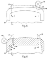
- Fig. 5 illustrates a second condition wherein the obstruction 46, instead of breaking the beam, strikes the mirror 39 and moves the mirror 39 about its hinge 42. The mirror is no longer in a position to reflect the beam to the radiation receiver 32; hence, an output indication is generated and the wheels are stopped.
- Fig. 6 illustrates a third condition wherein an obstruction 46 has struck a glancing blow on the corner of the bumper 22 outboard of the mirror 37. Because the bumper is mounted for lateral as well as longitudinal movement, the bumper 22 in this case moves laterally, so that the aperture 35 is no longer aligned with the radiation beam 38. Thus, a part of the bumper blocks the beam so it is not received at the radiation receiver 32 and the output indication is therefore generated.
- These three conditions of controlling the drive means 16 and 17 establish the perimeter guard as emitting a signal when the forward movement of the machine 10 encounters an obstruction.
- the machine 10 may have a rear bumper 48, shown in Fig. 1, with a similar proximity sensor to control the machine during reverse movements thereof.
- the mirrors 37 and 39 reflect the radiation beam around a corner of the frame 12.
- the apertures 35 are substantially parallel to the axis 20 to pass the radiation beam from the transmitter 31 to the receiver 32.
Abstract
Description
- U.S. Patent No. 4,446,602 discloses a light beam fence with a single beam reflected by mirrors to detect the presence of a person within a zone and to stop the operation of the machine in the zone. U.S. Patents Nos. 3,730,633 and 4,021,119 disclose an optical system for measuring the amount of intrusion of an object into a light beam split into two beams directed by mirrors. U.S. Patent No. 4,811,004 discloses an optical position sensing system for computer displays. The system uses light beams scanned by moving mirrors. U.S. Patent No. 4,564,085 discloses a light beam detecting system with a mirror which may swing out of the way to allow an alternate light path to be used.
- The above-mentioned prior art references are not well suited to a perimeter guard, especially to a perimeter guard on a movable machine, becuse the mirrors in the first-mentioned reference might be bumped by an obstruction and the remaining references do not show something which could be able to detect an obstruction in any position around the periphery of the machine.
- U.S. Patent No. 4,802,548 discloses an automatic guided vehicle having a flexible bumper carrying an emitter/receiver photocell thereon in electrical connection with a motor circuit and a brake circuit. If the vehicle strikes an obstruction the bumper is deflected causing the aligned emitter-receiver beam to be interrupted. As a result the motor circuit and the brake circuit will be operated to stop the vehicle until the beam is again transmitted to the photocell receiver.
- U.S. Patent No 4,730,690 discloses an arrangement for sensing an object relative to the side of a vehicle. A signalling apparatus delivers a signal to a reflective target and receives a reflection of the delivered signal therefrom. The signalling apparatus is fixed to the side of the vehicle whereas the reflective target is mounted at the side of a bumper, said side extending beyond the side of the vehicle itself. When hit from the side the bumper deflects and the emitted signal will not be properly reflected. This interuption in the signal flow is detected and used to control the movement of the vehicle.
- British Patent No. 2 116 765 discloses a safety system for a vehicle, comprising a pair of arms pivotably mounted at the rear of said vehicle for moving from a first position parallel to the rear surface of the vehicle to a second position at right angles to the rear surface when reverse gear of the vehicle is selected. One of the arms is provided with a light emitting device and the other arm is provided with a photocell. If the light beam to the photocell is interrupted or any of the arms displaced by an obstruction a switch is operated effecting actuation of the brake system of the vehicle for the purpose of stopping the vehicle.
- Accordingly, it is an object of the invention to provide a proximity sensor for a movable machine which constitutes a perimeter guard of the machine.
- It is another object of the invention to provide a proximity sensor for a movable machine utilizing a radiation beam as a perimeter guard.
- The objects will be achieved in a movable machine of the kind specified in the general part of claim 1 in which the features indicated in the characterizing part of said claim have been incorporated. Preferred embodiments have been included in the appending sub-claims.
- Other objects and a fuller understanding of the invention may be had by referring to the following description and claims, taken in conjunction with the accompanying drawings.
- Fig. 1
- is a perspective view of a machine embodying the proximity sensor of the invention;
- fig. 2
- is a perspective view of the machine, diagrammatically showing the parts therein;
- Fig. 3
- is a diagrammatic plan view showing the path of the radiation beam; and
- Fig.4-6
- show diagrammatically different ways of obstructing the beam.
- Figs. 1 and 2 show a
movable machine 10 with which theproximity sensor 11 may be used. The proximity sensor includes a perimeter guard around the periphery of the machine so that should an operator or observer violate the perimeter guard, a signal would be given to stop the movement of the machine. Preferably, the machine shown in Figs. 1 and 2 is a movable surface treatment machine having aframe 12 with aperiphery 13 of this frame. Drive means is provided, including drive...motors drive wheels machine 10 will move forwardly or backwardly parallel to a longitudinal fore andaft axis 20. - A
movable bumper 22 is provided on themachine 10. This bumper is movable by being supported from theframe 12 bysprings 23, the upper end of which is connected to the bumper and the lower end of which is connected to theframe 12. In this way, the bumper may move longitudinally as well as transversely relative to theframe 12. Thebumper 22 is L-shaped in cross section with ahorizontal plate 27 and avertical plate 28. Also, the bumper is C-shaped in plan view. - The surface treatment machine of Figs. 1 and 2 is shown as a robot vacuum cleaner with a self-winding
reel 24 for apower cord 25, which may be plugged into a convenience outlet for powering the machine. Avacuum hose 26 is provided for floor or off-the-floor cleaning functions when the vacuum cleaner is used in the manual mode rather than the robot mode. - The proximity sensor includes a
perimeter guard 30, which in turn includes aradiation transmitter 31 and aradiation receiver 32. The transmitter and receiver are mounted on theframe 12 to the rear of thebumper 22. - The radiation transmitter emits a radiation beam, e.g., infrared (focused) light from an LED (Light Emitting Diode) or possibly a laser, which in normal practice is designed to impinge on the
radiation receiver 32. This radiation beam from thetransmitter 31 passes through anaperture 35 in thebumper 22 and through awindow 36 in the front left corner of the bumper, the window being transparent to the frequency of the radiation. Thebeam 38 is reflected from amovable mirror 37, and has at least part thereof extending outside theperiphery 13 of the machine frame. In this case, the beam extends in front of the front of thebumper 22 and substantially parallel thereto, to be received and reflected by asecond mirror 39 at the right front corner of the machine. It is reflected from this mirror through atransparent window 40 in the front corner of the bumper and through anotherbumper aperture 35 to theradiation receiver 32. Themirrors hinges mirrors axis 20, respectively. By these two 45-degree angles, the radiation beam from theradiation transmitter 31 normally is received at theradiation receiver 32. When it is not so received, then an output indication is generated which is applied to a control means 43, which in turn controls the drive means 16 and 17. The perimeter guard includes movable means and these movable means includes themovable mirrors movable bumper 22. The movable mirrors are optical elements to act on the beam. - Fig. 3 illustrates diagrammatically the normal condition of the
radiation beam 38 emanating from theradiation transmitter 31 being reflected by themirrors radiation receiver 32. - Fig. 4 illustrates the perimeter guard when an
obstruction 46 intercepts thebeam 38. It does this forward of thebumper 22 at that portion wherein the beam extends outside theperiphery 13 of the machine. With theobstruction 46 being present, the beam no longer reaches theradiation receiver 32; hence, an output indication is generated so that the control means 43 stops the movable machine part, in this case, thewheels - Fig. 5 illustrates a second condition wherein the
obstruction 46, instead of breaking the beam, strikes themirror 39 and moves themirror 39 about itshinge 42. The mirror is no longer in a position to reflect the beam to theradiation receiver 32; hence, an output indication is generated and the wheels are stopped. - Fig. 6 illustrates a third condition wherein an
obstruction 46 has struck a glancing blow on the corner of thebumper 22 outboard of themirror 37. Because the bumper is mounted for lateral as well as longitudinal movement, thebumper 22 in this case moves laterally, so that theaperture 35 is no longer aligned with theradiation beam 38. Thus, a part of the bumper blocks the beam so it is not received at theradiation receiver 32 and the output indication is therefore generated. These three conditions of controlling the drive means 16 and 17 establish the perimeter guard as emitting a signal when the forward movement of themachine 10 encounters an obstruction. Themachine 10 may have a rear bumper 48, shown in Fig. 1, with a similar proximity sensor to control the machine during reverse movements thereof. - The
mirrors frame 12. Theapertures 35 are substantially parallel to theaxis 20 to pass the radiation beam from thetransmitter 31 to thereceiver 32. - The present disclosure includes that contained in the appended claims, as well as that of the foregoing description. Although this invention has been described in its preferred form with a certain degree of particularity, it is understood that the present disclosure of the preferred form has been made only by way of example, and that numerous changes in the details of construction and the combination and arrangement of parts, and in the details of the circuit and the combination and arrangement of circuit elements may be resorted to without departing from the spirit and scope of the invention as hereinafter claimed.
Claims (11)
- A proximity sensor (11) for a movable machine (10), preferably a movable surface treatment machine, said machine (10) having a frame (12) with a periphery (13), a perimeter guard (30) with a radiation transmitter (31) to project a radiation beam (38), a radiation receiver (32) mounted to receive said radiation beam (38) for producing an output indication when it is not receiving the radiation beam (38), drive means (16,17,18,19) to drive said machine (10), control means (43) for said drive means (16,17,18,19) responsive to said output indication, said perimeter guard (30) further including a movable means (37,39) acting on said radiation beam (38) and capable of being moved by an obstruction to inhibit said radiation receiver (32) from receiving said radiation beam (38), said radiation transmitter (31) normally projecting said radiation beam (38) such that at least part of said beam extends outside said periphery (13), whereby movement of the movable means (37,39) by an obstruction inhibits said radiation beam (38) from being received at said receiver (32) and thus generates said output indication to control said drive means (16,17,18,19), characterized in that both the radiation transmitter (31) and the radiation receiver (32) are mounted within and away from said periphery (13) and in that the movable means (37,39) is an optical system.
- A proximity sensor according to claim 1, characterized in that said optical system includes a first movable mirror (37) reflecting said radiation beam (38) around a corner of said frame (12).
- A proximity sensor according to claim 2, characterized in that spring means are provided for urging said mirror (37) outwardly of said frame (12), stop means being provided for normally position said mirror (37) at a 45-degree angle relative to a fore and aft longitudinal axis of said frame (12).
- A proximity sensor according to claim 2 or 3, characterized in that said optical system includes a second mirror (39) pivotably mounted to said frame (12) at a second corner of said frame, spring means being provided for urging said second mirror (39) outwardly in front of said frame (12) and stop means being provided to normally position said second mirror (39) at a minus 45-degree angle relative to a fore and aft longitudinal axis of said frame (12).
- A proximity sensor according to claim 4, characterized in that first and second windows (36,40) are provided on the machine (10) which are transparent to said radiation beam (38) with said first window (36) mounted between said radiation transmitter (31) and said first mirror (37) and said second window (40) mounted between said second mirror (39) and the receiver (32).
- A proximity sensor according to any of the preceding claims, characterized in that said machine (10) is a robot vacuum cleaner.
- A proximity sensor according to any of the preceding claims, characterized in that a bumper (22) is mounted on the front side of the frame (12) and that said optical system (37,39) is mounted on said bumper (22).
- A proximity sensor according to claim 7, characterized in that the bumper (22) is mounted for movement relative to said frame (12) along a longitudinal axis of the frame (12) and for transverse movement relative to said axis.
- A proximity sensor according to claim 8, characterized in that the optical system includes a first mirror (37) and a first aperture (35) in said bumper (22) for transmission of a radiation beam (38) substantially parallel to said axis, said first aperture (35) being located between said radiation transmitter (31) and said first mirror (37), and a second mirror (39) and a second aperture (35) in the bumper (22) for transmission of said radiation beam (38) substantially parallel to said axis, said second aperture (35) being located between said radiation receiver (32) and said second mirror (39), whereby forward movement of the machine (10) may cause it to strike an obstruction moving the bumper (22) and causing at least one of said apertures (35) to move laterally of said axis and therefore inhibiting said radiation beam (38) from being received at said receiver (32) to control said drive means (16,17,18,19).
- A proximity sensor according to claim 7, characterized in that said bumper (22) is mounted for movement relative to said frame (12) transversely to a longitudinal axis of said frame and that beam blocking means (37,39) are provided on said bumper (22) laterally of the path of said radiation beam (38), whereby movement of the machine (10) may cause it to strike an obstruction, moving the bumper (22) laterally and therefore inhibiting said radiation beam (38) from being received at said receiver (32) to control said drive means (16,17,18,19).
- A proximity sensor according to claim 11, characterized in that means (37,39) are provided for directing at least part of said radiation beam (38) generally parallel to and in front of said bumper (22), whereby forward movement of the machine (10) may cause an obstruction to break the radiation beam (38) to control said drive means (16,17,18,19).
Applications Claiming Priority (3)
| Application Number | Priority Date | Filing Date | Title |
|---|---|---|---|
| US07/458,318 US5023444A (en) | 1989-12-28 | 1989-12-28 | Machine proximity sensor |
| PCT/SE1990/000867 WO1991010221A1 (en) | 1989-12-28 | 1990-12-21 | Machine proximity sensor |
| US458318 | 2003-06-11 |
Publications (2)
| Publication Number | Publication Date |
|---|---|
| EP0461235A1 EP0461235A1 (en) | 1991-12-18 |
| EP0461235B1 true EP0461235B1 (en) | 1995-11-08 |
Family
ID=23820312
Family Applications (1)
| Application Number | Title | Priority Date | Filing Date |
|---|---|---|---|
| EP91901941A Expired - Lifetime EP0461235B1 (en) | 1989-12-28 | 1990-12-21 | Machine proximity sensor |
Country Status (5)
| Country | Link |
|---|---|
| US (1) | US5023444A (en) |
| EP (1) | EP0461235B1 (en) |
| JP (1) | JPH04504761A (en) |
| DE (1) | DE69023492T2 (en) |
| WO (1) | WO1991010221A1 (en) |
Families Citing this family (44)
| Publication number | Priority date | Publication date | Assignee | Title |
|---|---|---|---|---|
| DE4205251A1 (en) * | 1992-02-21 | 1993-08-26 | Hella Kg Hueck & Co | DEVICE FOR MONITORING THE CLOSING PROCESS OF A MOTOR-DRIVEN WINDOW WINDOW, IN PARTICULAR A MOTOR VEHICLE WINDOW WINDOW |
| US5440216A (en) * | 1993-06-08 | 1995-08-08 | Samsung Electronics Co., Ltd. | Robot cleaner |
| US5465807A (en) * | 1994-06-27 | 1995-11-14 | Harold Josephs | Safety guard for hand trucks or lift gates |
| US5703450A (en) * | 1994-06-27 | 1997-12-30 | Josephs; Harold | Safety guard for pedestrian-operated machines having rotatable blades |
| WO2000007492A1 (en) * | 1998-07-31 | 2000-02-17 | Volker Sommer | Household robot for the automatic suction of dust from the floor surfaces |
| GB2385182B (en) * | 2002-02-06 | 2006-06-21 | Mechan Controls Ltd | Safety switching devices |
| US7805220B2 (en) * | 2003-03-14 | 2010-09-28 | Sharper Image Acquisition Llc | Robot vacuum with internal mapping system |
| US7801645B2 (en) * | 2003-03-14 | 2010-09-21 | Sharper Image Acquisition Llc | Robotic vacuum cleaner with edge and object detection system |
| US20050010331A1 (en) * | 2003-03-14 | 2005-01-13 | Taylor Charles E. | Robot vacuum with floor type modes |
| US20040236468A1 (en) * | 2003-03-14 | 2004-11-25 | Taylor Charles E. | Robot vacuum with remote control mode |
| US20040200505A1 (en) * | 2003-03-14 | 2004-10-14 | Taylor Charles E. | Robot vac with retractable power cord |
| KR100507926B1 (en) * | 2003-06-30 | 2005-08-17 | 삼성광주전자 주식회사 | Device for driving of robot cleaner |
| US20060020369A1 (en) * | 2004-03-11 | 2006-01-26 | Taylor Charles E | Robot vacuum cleaner |
| KR100633444B1 (en) * | 2005-02-24 | 2006-10-13 | 삼성광주전자 주식회사 | Robot cleaner and method of control thereof |
| US7266477B2 (en) * | 2005-06-22 | 2007-09-04 | Deere & Company | Method and system for sensor signal fusion |
| CN100586356C (en) * | 2005-07-08 | 2010-02-03 | 伊莱克斯公司 | Robotic cleaning device |
| DE102010046327B4 (en) * | 2010-09-23 | 2021-10-28 | Kuka Roboter Gmbh | Monitoring a mobile manipulator |
| US9939529B2 (en) | 2012-08-27 | 2018-04-10 | Aktiebolaget Electrolux | Robot positioning system |
| CN105101854A (en) | 2013-04-15 | 2015-11-25 | 伊莱克斯公司 | Robotic vacuum cleaner |
| WO2014169944A1 (en) | 2013-04-15 | 2014-10-23 | Aktiebolaget Electrolux | Robotic vacuum cleaner with protruding sidebrush |
| KR102393550B1 (en) | 2013-12-19 | 2022-05-04 | 에이비 엘렉트로룩스 | Prioritizing cleaning areas |
| CN105849660B (en) | 2013-12-19 | 2020-05-08 | 伊莱克斯公司 | Robot cleaning device |
| CN105829985B (en) | 2013-12-19 | 2020-04-07 | 伊莱克斯公司 | Robot cleaning device with peripheral recording function |
| EP3082541B1 (en) | 2013-12-19 | 2018-04-04 | Aktiebolaget Electrolux | Adaptive speed control of rotating side brush |
| JP6494118B2 (en) | 2013-12-19 | 2019-04-03 | アクチエボラゲット エレクトロルックス | Control method of robot cleaner associated with detection of obstacle climbing, and robot cleaner, program, and computer product having the method |
| US10045675B2 (en) | 2013-12-19 | 2018-08-14 | Aktiebolaget Electrolux | Robotic vacuum cleaner with side brush moving in spiral pattern |
| WO2015090399A1 (en) | 2013-12-19 | 2015-06-25 | Aktiebolaget Electrolux | Robotic cleaning device and method for landmark recognition |
| EP3082539B1 (en) | 2013-12-20 | 2019-02-20 | Aktiebolaget Electrolux | Dust container |
| WO2016005012A1 (en) | 2014-07-10 | 2016-01-14 | Aktiebolaget Electrolux | Method for detecting a measurement error in a robotic cleaning device |
| WO2016037635A1 (en) | 2014-09-08 | 2016-03-17 | Aktiebolaget Electrolux | Robotic vacuum cleaner |
| WO2016037636A1 (en) | 2014-09-08 | 2016-03-17 | Aktiebolaget Electrolux | Robotic vacuum cleaner |
| WO2016091291A1 (en) | 2014-12-10 | 2016-06-16 | Aktiebolaget Electrolux | Using laser sensor for floor type detection |
| CN107072454A (en) | 2014-12-12 | 2017-08-18 | 伊莱克斯公司 | Side brush and robot cleaner |
| CN107003669B (en) | 2014-12-16 | 2023-01-31 | 伊莱克斯公司 | Experience-based road sign for robotic cleaning devices |
| JP6532530B2 (en) | 2014-12-16 | 2019-06-19 | アクチエボラゲット エレクトロルックス | How to clean a robot vacuum cleaner |
| US11099554B2 (en) | 2015-04-17 | 2021-08-24 | Aktiebolaget Electrolux | Robotic cleaning device and a method of controlling the robotic cleaning device |
| WO2017036532A1 (en) | 2015-09-03 | 2017-03-09 | Aktiebolaget Electrolux | System of robotic cleaning devices |
| CN108603935A (en) | 2016-03-15 | 2018-09-28 | 伊莱克斯公司 | The method that robotic cleaning device and robotic cleaning device carry out cliff detection |
| CN109068908B (en) | 2016-05-11 | 2021-05-11 | 伊莱克斯公司 | Robot cleaning device |
| US10580268B2 (en) | 2016-06-14 | 2020-03-03 | Mighty Oak Medical, Inc. | System and method for determining a person within a predetermined distance of an emitter of ionizing energy |
| US10845778B2 (en) * | 2017-03-30 | 2020-11-24 | Lincoln Global, Inc. | Workpiece positioner and welding sequencer |
| JP7243967B2 (en) | 2017-06-02 | 2023-03-22 | アクチエボラゲット エレクトロルックス | Method for Detecting Level Differences on a Surface in Front of a Robotic Cleaning Device |
| JP6989210B2 (en) | 2017-09-26 | 2022-01-05 | アクチエボラゲット エレクトロルックス | Controlling the movement of robot cleaning devices |
| CN109808789A (en) * | 2017-11-21 | 2019-05-28 | 富泰华工业(深圳)有限公司 | Wheeled mobile robot it is anti-walk deflection device |
Family Cites Families (14)
| Publication number | Priority date | Publication date | Assignee | Title |
|---|---|---|---|---|
| US3730633A (en) * | 1970-12-31 | 1973-05-01 | Aerotherm Corp | Photometric detector and measuring system |
| US4021119A (en) * | 1975-06-24 | 1977-05-03 | Honeywell Inc. | Position gauge |
| CA1109539A (en) * | 1978-04-05 | 1981-09-22 | Her Majesty The Queen, In Right Of Canada, As Represented By The Ministe R Of Communications | Touch sensitive computer input device |
| SE416924B (en) * | 1979-05-18 | 1981-02-16 | Per Eric Sjoberg | DEVICE FOR MOTOR-DRIVEN VEHICLES TO DISCOVER ONE OF THE VEHICLES EXISTING IN THE WAY OF THE VEHICLE |
| SE428250B (en) * | 1979-05-31 | 1983-06-13 | Bert Jonsson | PHOTOELECTRIC DEVICE FOR SENSING FORM |
| DE3032584C2 (en) * | 1980-08-29 | 1982-06-24 | Trützschler GmbH & Co KG, 4050 Mönchengladbach | Device for monitoring and securing accessible danger areas on power-driven textile machines |
| GB2116765A (en) * | 1982-02-22 | 1983-09-28 | Ogden Electronics Ltd | A safety system for a vehicle |
| JPS59140994A (en) * | 1983-01-31 | 1984-08-13 | 株式会社小松製作所 | Ray type safety device |
| US4564085A (en) * | 1985-01-22 | 1986-01-14 | Towmotor Corporation | Controlling arrangement |
| US4880969A (en) * | 1986-04-30 | 1989-11-14 | Litton Systems, Inc. | Optical touch panel with heat sink |
| US4730690A (en) * | 1986-09-02 | 1988-03-15 | Caterpillar Industrial Inc. | Object sensing arrangement |
| CH671295A5 (en) * | 1987-02-27 | 1989-08-15 | Jd Technologie Ag | |
| US4811004A (en) * | 1987-05-11 | 1989-03-07 | Dale Electronics, Inc. | Touch panel system and method for using same |
| US4802548A (en) * | 1987-12-21 | 1989-02-07 | Munck Automation Technology, Inc. | Automatic guided vehicle safety system |
-
1989
- 1989-12-28 US US07/458,318 patent/US5023444A/en not_active Expired - Fee Related
-
1990
- 1990-12-21 EP EP91901941A patent/EP0461235B1/en not_active Expired - Lifetime
- 1990-12-21 WO PCT/SE1990/000867 patent/WO1991010221A1/en active IP Right Grant
- 1990-12-21 JP JP3502120A patent/JPH04504761A/en active Pending
- 1990-12-21 DE DE69023492T patent/DE69023492T2/en not_active Expired - Fee Related
Also Published As
| Publication number | Publication date |
|---|---|
| WO1991010221A1 (en) | 1991-07-11 |
| DE69023492D1 (en) | 1995-12-14 |
| DE69023492T2 (en) | 1996-03-21 |
| EP0461235A1 (en) | 1991-12-18 |
| US5023444A (en) | 1991-06-11 |
| JPH04504761A (en) | 1992-08-20 |
Similar Documents
| Publication | Publication Date | Title |
|---|---|---|
| EP0461235B1 (en) | Machine proximity sensor | |
| US4668859A (en) | Protective zone device for a vehicle | |
| EP0826095B1 (en) | Power driven venting of a vehicle | |
| US6765192B2 (en) | Processing system with protective device for secure processing table | |
| US3664701A (en) | Safety bumper for driverless vehicle | |
| US4968878A (en) | Dual bumper-light curtain obstacle detection sensor | |
| US4239961A (en) | Photoelectric light curtain using retroreflector | |
| EP0157221A1 (en) | Laser shielding device | |
| US20010042820A1 (en) | Optoelectronic system for an automatic vehicle door closure | |
| US4783618A (en) | Apparatus and method for controlling apparatus including a plurality of guided units | |
| US6147625A (en) | Device for positioning motor vehicles in front of a car wash | |
| KR19990062834A (en) | Outdoor work platform with pit and / or obstacle detection and avoidance system | |
| US4958068A (en) | Dual bumper-light curtain obstacle detection sensor | |
| US7643906B2 (en) | Obstacle and cliff avoiding system and method thereof | |
| WO2011031709A1 (en) | Load handling bumper for material handling device | |
| JP2001511252A (en) | Optical transmitting and receiving device | |
| US4823901A (en) | Apparatus and method for detecting faults in an obstacle detection system | |
| US7889325B2 (en) | Vehicle-purpose object sensing apparatus | |
| US5625447A (en) | Scanning type laser radar system for vehicle | |
| KR20190141345A (en) | Lidar sensor and control method thereof | |
| US4802548A (en) | Automatic guided vehicle safety system | |
| EP0818402B1 (en) | Refuse collection vehicle provided with safety means | |
| JPH09158258A (en) | Monitoring device of construction equipment | |
| JPH1031064A (en) | Scan type laser radar device | |
| US5642869A (en) | Apparatus for detecting the distance between two objects |
Legal Events
| Date | Code | Title | Description |
|---|---|---|---|
| PUAI | Public reference made under article 153(3) epc to a published international application that has entered the european phase |
Free format text: ORIGINAL CODE: 0009012 |
|
| 17P | Request for examination filed |
Effective date: 19910807 |
|
| AK | Designated contracting states |
Kind code of ref document: A1 Designated state(s): BE CH DE FR GB IT LI NL SE |
|
| 17Q | First examination report despatched |
Effective date: 19940316 |
|
| GRAA | (expected) grant |
Free format text: ORIGINAL CODE: 0009210 |
|
| AK | Designated contracting states |
Kind code of ref document: B1 Designated state(s): BE CH DE FR GB IT LI NL SE |
|
| PG25 | Lapsed in a contracting state [announced via postgrant information from national office to epo] |
Ref country code: IT Free format text: LAPSE BECAUSE OF FAILURE TO SUBMIT A TRANSLATION OF THE DESCRIPTION OR TO PAY THE FEE WITHIN THE PRESCRIBED TIME-LIMIT;WARNING: LAPSES OF ITALIAN PATENTS WITH EFFECTIVE DATE BEFORE 2007 MAY HAVE OCCURRED AT ANY TIME BEFORE 2007. THE CORRECT EFFECTIVE DATE MAY BE DIFFERENT FROM THE ONE RECORDED. Effective date: 19951108 Ref country code: BE Effective date: 19951108 Ref country code: NL Free format text: LAPSE BECAUSE OF NON-PAYMENT OF DUE FEES Effective date: 19951108 |
|
| REF | Corresponds to: |
Ref document number: 69023492 Country of ref document: DE Date of ref document: 19951214 |
|
| PGFP | Annual fee paid to national office [announced via postgrant information from national office to epo] |
Ref country code: CH Payment date: 19951231 Year of fee payment: 6 |
|
| PG25 | Lapsed in a contracting state [announced via postgrant information from national office to epo] |
Ref country code: SE Effective date: 19960208 Ref country code: GB Effective date: 19960208 |
|
| ET | Fr: translation filed | ||
| NLV1 | Nl: lapsed or annulled due to failure to fulfill the requirements of art. 29p and 29m of the patents act | ||
| REG | Reference to a national code |
Ref country code: CH Ref legal event code: PL |
|
| PG25 | Lapsed in a contracting state [announced via postgrant information from national office to epo] |
Ref country code: DE Effective date: 19960903 |
|
| PLBE | No opposition filed within time limit |
Free format text: ORIGINAL CODE: 0009261 |
|
| STAA | Information on the status of an ep patent application or granted ep patent |
Free format text: STATUS: NO OPPOSITION FILED WITHIN TIME LIMIT |
|
| GBPC | Gb: european patent ceased through non-payment of renewal fee |
Effective date: 19960208 |
|
| 26N | No opposition filed | ||
| PG25 | Lapsed in a contracting state [announced via postgrant information from national office to epo] |
Ref country code: FR Effective date: 19961031 |
|
| REG | Reference to a national code |
Ref country code: FR Ref legal event code: ST |
|
| PG25 | Lapsed in a contracting state [announced via postgrant information from national office to epo] |
Ref country code: CH Free format text: LAPSE BECAUSE OF FAILURE TO SUBMIT A TRANSLATION OF THE DESCRIPTION OR TO PAY THE FEE WITHIN THE PRESCRIBED TIME-LIMIT Effective date: 19961231 Ref country code: LI Free format text: LAPSE BECAUSE OF FAILURE TO SUBMIT A TRANSLATION OF THE DESCRIPTION OR TO PAY THE FEE WITHIN THE PRESCRIBED TIME-LIMIT Effective date: 19961231 |
|
| PG25 | Lapsed in a contracting state [announced via postgrant information from national office to epo] |
Ref country code: FR Effective date: 19951231 |