EP0460913A2 - A lighting unit having a lamp and a reflector - Google Patents
A lighting unit having a lamp and a reflector Download PDFInfo
- Publication number
- EP0460913A2 EP0460913A2 EP91305037A EP91305037A EP0460913A2 EP 0460913 A2 EP0460913 A2 EP 0460913A2 EP 91305037 A EP91305037 A EP 91305037A EP 91305037 A EP91305037 A EP 91305037A EP 0460913 A2 EP0460913 A2 EP 0460913A2
- Authority
- EP
- European Patent Office
- Prior art keywords
- film
- light
- layer
- interference multi
- lighting unit
- Prior art date
- Legal status (The legal status is an assumption and is not a legal conclusion. Google has not performed a legal analysis and makes no representation as to the accuracy of the status listed.)
- Withdrawn
Links
Images


Classifications
-
- F—MECHANICAL ENGINEERING; LIGHTING; HEATING; WEAPONS; BLASTING
- F21—LIGHTING
- F21V—FUNCTIONAL FEATURES OR DETAILS OF LIGHTING DEVICES OR SYSTEMS THEREOF; STRUCTURAL COMBINATIONS OF LIGHTING DEVICES WITH OTHER ARTICLES, NOT OTHERWISE PROVIDED FOR
- F21V7/00—Reflectors for light sources
- F21V7/04—Optical design
- F21V7/06—Optical design with parabolic curvature
-
- H—ELECTRICITY
- H01—ELECTRIC ELEMENTS
- H01K—ELECTRIC INCANDESCENT LAMPS
- H01K1/00—Details
- H01K1/28—Envelopes; Vessels
- H01K1/32—Envelopes; Vessels provided with coatings on the walls; Vessels or coatings thereon characterised by the material thereof
-
- F—MECHANICAL ENGINEERING; LIGHTING; HEATING; WEAPONS; BLASTING
- F21—LIGHTING
- F21S—NON-PORTABLE LIGHTING DEVICES; SYSTEMS THEREOF; VEHICLE LIGHTING DEVICES SPECIALLY ADAPTED FOR VEHICLE EXTERIORS
- F21S41/00—Illuminating devices specially adapted for vehicle exteriors, e.g. headlamps
- F21S41/10—Illuminating devices specially adapted for vehicle exteriors, e.g. headlamps characterised by the light source
- F21S41/12—Illuminating devices specially adapted for vehicle exteriors, e.g. headlamps characterised by the light source characterised by the type of emitted light
- F21S41/13—Ultraviolet light; Infrared light
-
- F—MECHANICAL ENGINEERING; LIGHTING; HEATING; WEAPONS; BLASTING
- F21—LIGHTING
- F21S—NON-PORTABLE LIGHTING DEVICES; SYSTEMS THEREOF; VEHICLE LIGHTING DEVICES SPECIALLY ADAPTED FOR VEHICLE EXTERIORS
- F21S41/00—Illuminating devices specially adapted for vehicle exteriors, e.g. headlamps
- F21S41/30—Illuminating devices specially adapted for vehicle exteriors, e.g. headlamps characterised by reflectors
- F21S41/37—Illuminating devices specially adapted for vehicle exteriors, e.g. headlamps characterised by reflectors characterised by their material, surface treatment or coatings
-
- F—MECHANICAL ENGINEERING; LIGHTING; HEATING; WEAPONS; BLASTING
- F21—LIGHTING
- F21V—FUNCTIONAL FEATURES OR DETAILS OF LIGHTING DEVICES OR SYSTEMS THEREOF; STRUCTURAL COMBINATIONS OF LIGHTING DEVICES WITH OTHER ARTICLES, NOT OTHERWISE PROVIDED FOR
- F21V7/00—Reflectors for light sources
- F21V7/22—Reflectors for light sources characterised by materials, surface treatments or coatings, e.g. dichroic reflectors
-
- F—MECHANICAL ENGINEERING; LIGHTING; HEATING; WEAPONS; BLASTING
- F21—LIGHTING
- F21V—FUNCTIONAL FEATURES OR DETAILS OF LIGHTING DEVICES OR SYSTEMS THEREOF; STRUCTURAL COMBINATIONS OF LIGHTING DEVICES WITH OTHER ARTICLES, NOT OTHERWISE PROVIDED FOR
- F21V9/00—Elements for modifying spectral properties, polarisation or intensity of the light emitted, e.g. filters
Definitions
- the first film 25 coated on the outer surface of the tube 13 has the function of passing (transmitting) light of a specified range of wavelengths i.e., visible light andfor suppressing other wavelengths of light passing through, i.e., for reflecting infrared radiation
- the second film 35,coated on the surface of the reflecting base member 33 has the function lf reflecting the desired wavelengths of light, i.e. visible light passing through the first film 25, and for suppressing other wavelengths i. e. so that infrared radiation is not reflected thereon, but instead the infrared radiation passes through.
- the first interference multilayer filter of the first film 25 is a visible light transparency/infrared radiation reflective film
- the second film 35 is a visible light reflective/infrared radiation transmissive film
- each layer of the second interference multi-layer filter of the second film 35 is thin in an area having a small incident angle ⁇ 3 of light emitted from the filament 23 and is thicker in an area having a larger incident angle ⁇ 4 of light emitted from the filament 23 since the area near the filament 23 has a small incident angle ⁇ 3 of light and the area far from the filament 23 has a large incident angle ⁇ 4 of light.
- the thickness t3 of the second film 23 in the area far from the opening 32 of the reflector 31 is smaller than the thickness t4 of the second film 35 in the area near the opening 32 of the reflector 31.
- the thickness t1 of the first film 25 at the portion where the incident angle ⁇ 1 is small is smaller than the thickness t2 of the first film 25 at the portion where the incident angle ⁇ 2 is large, as shown in Fig. 4, the multiplied value of d.cos ⁇ is kept constant, and therefore the variaton of the wavelength ⁇ of the transmitted visible light and the reflected infrared radiation is suppressed.
- the structure of the interference multi-layer filters of the first film 25 and the second film 35 is not limited to the embodiments explained above.
- the refractive index of each layer of the interference multi-layer filters of the first film 25 and the second film 35 may vary according to the position of each layer of the interference multi-layer filters instead of the thickness of each layer of the interference multilayer filters of the embodiments explained above varying.
- the similar result can be obtained by varying the refractive index n of each layer of the interference multi-layer filters of the first film 25 and the second film 35 according to the position of each layer of the interference multi-layer filters.
- the present invention overcomes the disadvantages of the prior art and provides an improved layer for preventing glass pieces from scattering when the glass envelope of the lamp is broken.
Landscapes
- Engineering & Computer Science (AREA)
- General Engineering & Computer Science (AREA)
- Physics & Mathematics (AREA)
- Spectroscopy & Molecular Physics (AREA)
- Optical Filters (AREA)
Abstract
The lighting unit of the present invention is composed of a lamp (11) having a first interference multi-layer filter as the first film (25) and a reflector (31) having a second interference multi-layer filter as the second film (35). The first interference multi-layer filter forms a visible light transparency/ infrared-ray reflecting film and the second interference multi-layer filter forms a infrared-ray transmitting/ visible light reflecting film.
Both the first interference multi-layer filter and the second interference multi-layer filter are likely to cause the range of wavelength of light transmitting and light reflecting to vary from the specific range. Therefore both the first film (25) and the second film (35) have means for preventing the above described variation (thickness varying according to the position of the films (25) and (35)).
Description
- The present invention relates to a lighting unit having a lamp and a reflector, and especially to a lighting unit with both the lamp and the reflector provided with an interference multi-layer filter.
- A lighting unit having a lamp and a reflector, each of which is provided with an interference multi-layer filter
is already known in the art. The lamp of the conventional lighting unit is a halogen lamp coated with a first interference multi-layer filter (film) which enables visible light to pass (transmit) therethrough and infrared-ray to reflect thereon. The reflector of the conventional lighting unit has a second interference multi-layer filter (film) which enables visible light to reflect thereon and infrared-ray to pass (transmit) therethrough. The second interference multi-layer filter is coated on the reflecting surface of a reflecting base of the reflector and is called a dichroic mirror film. The reflector is shaped into a paraboloid of revolution and surrounds the halogen lamp. Both the first and second interference multi-layer filters are composed of multiple layers of two kinds of different refractive index layers which are alternately disposed on the surfaces of the lamp and the reflecting base of the reflector. - This lighting unit is used for spot-lighting in stores since this lighting unit has high efficiency and high color temperature, as compared with a lighting unit not having an interference multi-layer filter. Because infrared-rays reflected at the first interference multi-layer filter return to the filament of the lamp and heat the filament, the lamp has a high efficiency. Furthermore, light reflected at the second interference multi-layer filter does not include a high amount of infrared-rays since the second interference multi-layer filter enables visible light to reflect thereon and infrared-rays to pass therethrough, and therefore this lighting unit can prevent heat damage to abjects to be illuminated and can emit light of high color temperature, for example 3050-3600°K.
- However, this lighting unit has a shortcoming in that a color pattern having a ring shape appears on the surface of the illuminated objects. In this color pattern, the color of green is strong in the periphery of the lighting area. The interference multi-layer filters are thought to have a problem in that they emit a greenish light to the periphery of the lighting area. An additional shortcoming is that light of sufficiently high color temperature is not obtained.
- Although the structure described below is not believed to constitute prior art with respect to the present invention, it is described to enable a better understanding of the present invention. It has been proposed that the second interference multi-layer filter may have a thickness which varies according to its position on the reflecting base of the reflector, in order to overcome the above mentioned shortcomings. However, this lamp unit also has the disadvantages of generating an unwanted color pattern and does not emit light of sufficiently high color temperature.
- Accordingly, the present invention seeks to eliminate a color pattern of light emitted from the lighting unit and appearing on the surface of a lighting object. The present invention further seeks to increase the color temperature of a lighting unit.
- Thus, the lighting unit of the present invention comprises;
a lamp having
a hollow tube having a surface,
a filament included in said tube for generating multiple wavelength light, and
a first film on the surface of said tube for passing light of a specified range of wavelengths and for suppressing other wavelengths of light from passing therethrough, said first film having first means for suppressing a variation, at different points of the film, of the wavelength of said light which passes therethrough; and
a second film surrounding said lamp for reflecting said light of specified range of wavelenghts thereon and for suppressing other wavelengths of light from reflecting thereon, said second film having second means for suppressing a variation, at different points of the film, of the wavelength of said light which reflects thereon. - For better understanding of the present invention, and to show how it may be brought into effect, reference will now be made, by way of example, to the following drawings, in which:
- Fig.1 is a partial sectional side view of a lighting unit according to the first embodiment of the present invention;
- Fig. 2 is a partial sectional view of the first interference multi-layer filter of the first film and the tube of Fig. 1;
- Fig. 3 is a partial sectional view of the second interference multi-layer filter of the second film and the reflecting base of Fig. 1;
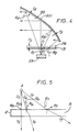
- Fig. 4 is a partial modified sectional side view of Fig. 1, for explaining the interference multi-layer filter of the first and second films varying their thickness;
- Fig. 5 is a schematic diagram for explaining the relation between the incident angle of light and the incident position of light for interference multi-layer filters;
- Fig. 6 is a partial sectional view of the interference multi-layer filter of the first film and the tube according to the second embodiment of the present invention; and
- Fig. 7 is a partial sectional side view of a lighting unit according to the third embodiment of the present invention.
- Referring to the accompanying drawings, embodiments of the present invention will be described. However, in the drawings, the same numerals are applied to the similar elements in the drawings, and therefore the detailed descriptions thereof are not repeated.
- Fig. 1 is a partial sectional side view of a lighting unit according to the first embodiment of the present invention. The lighting unit is composed of a
halogen lamp 11 and arefletor 31. Thehalogen lamp 11 comprises a cylindricalhollow tube 13 which is about 12 mm in outer diameter and about 40 mm in length. Thetube 13 is made of quartz glass. Thetube 13 has apinch seal portion 15 at one end thereof where a pair of molybdenum leaves 17a and 17b connect a pair of inner wires 19a and 19b with a pair of outer wires 21a and 21b The pair of inner wires 19a and 19b support atungsten coil filament 23 which is about 1.5 mm in outer diameter and about 5 mm in length. Thetungsten coil filament 23 is located in thetube 13 so that the central axis of thetungsten coil filament 23 coincides with the central axis O₁-O₁ of thetube 13. Thetube 13 contains a designated amount of argon gas and halogen gas therein. Thefirst film 25 made of a first interference multi-layer filter is provided on the outer surface of thetube 13 other than on thepinch seal portion 15 and on the end of thetube 13 opposite thepinch seal portion 15. Alternatively thefirst film 25 may be provided on the inner surface of thetube 13 instead of on the outer surface. Thefirst film 25 is explained later in detail. The opposite end of thetube 13 has ashielding film 27 on the outer surface for shielding light emitted from thefilament 23. Theshielding film 27 is made of light absorption materials such as cobalt oxide (CoO), nickel oxide (NiO) and so on, which forms a black film. It may be made of fine particle materials such as titanium oxide (TiO₂), aluminium oxide (Al₂O₃) and so on, which reflect light. - The
halogen lamp 11 above described is surrounded by thereflector 31. Thereflector 31 has a reflectingbase member 33 and asecond film 35 which is made of a second interference multi-layer filter. The reflectingbase member 33 is made of aluminium, but it may be made of glass materials. The reflectingbase member 33 forms a reflectingportion 331 and abase end portion 333. The reflectingportion 331 has anopening 32 at one end for emitting light and is connected with thebase end portion 333 at the other end thereof. The inner surface of the reflectingportion 331 is formed in a shape of a paraboloid of revolution and is coated with thesecond film 35 made of the second interference multi-layer filter. Thebase end portion 333 of the reflectingbase member 33 is formed in a cylindrical hollow shape and supports thelamp 11 therein. The reflectingportion 331 and thebase end portion 333 have a common central axis O₂-O₂ and thelamp 11 is fixed to the ,base end portion 333 withadhesives 41, such as cement, so that the central axis O₁-O₁ of thelamp 11 coincides with the central axis O₂-O₂ of the reflectingbase member 33 and that thepinch seal portion 15 of thelamp 11 faces to the inner surface of thebase end portion 333 of the reflectingbase member 33. Theadhesives 41 are filled between the inner surface of thebase end portion 333 of the reflectingbase member 33 and the outer surface of thepinch seal portion 15 of thelamp 11. - The
first film 25 coated on the outer surface of thetube 13 has the function of passing (transmitting) light of a specified range of wavelengths i.e., visible light andfor suppressing other wavelengths of light passing through, i.e., for reflecting infrared radiation Thesecond film 35,coated on the surface of the reflectingbase member 33, has the function lf reflecting the desired wavelengths of light, i.e. visible light passing through thefirst film 25, and for suppressing other wavelengths i. e. so that infrared radiation is not reflected thereon, but instead the infrared radiation passes through. In other words, the first interference multilayer filter of thefirst film 25 is a visible light transparency/infrared radiation reflective film and thesecond film 35 is a visible light reflective/infrared radiation transmissive film - Both the
first film 25 and thesecond film 35 are made of interference multi-layer filters which are composed of multiple layers, for example 9-17 layers, of two kinds of different refractive index layers which are alternately disposed on the surfaces of thetube 13 of thelamp 11 and the reflectingbase member 33 of thereflector 31, as shown in Fig. 2 and Fig. 3. Thelayers 51 having high refractive index are made of amorphous metal oxide such as titanium oxide (TiO₂), tantalum oxide (Ta₂O₅), zirconium oxide (ZrO₂) , zinc sulfide (ZnS) and so on, and thelayers 53 having low refractive index are made of amorphous metal oxide such as silicon oxide (SiO₂), magnesium fluoride (MgF₂) and so on. - Each layer of the interference multi-layer filters of the
first film 25 and thesecond film 35 has a predetermined thickness according to the desired wavelengths of light passing therethrough and to other wavelengths of light to be suppressed. - Futhermore, the thickness of each layer of the interference multi-layer filters of the
first film 25 and thesecond film 35 varies continuously according to the position thereof, as is shown in Fig.2-Fig.4. This is one feature of the present invention which is different from the conventional lighting unit. Each layer of the first interference multi-layer filter of thefirst film 25 is thin in an area close to thefilament 23 and is thicker in an area further away from thefilament 23. - The thickness of each layer in the area close to the
filament 23 is smaller than the thickness of each layer in the area further away from thefilament 23. As a result, the thickness t₁ of thefirst film 25 in the area close to thefilament 23 is smaller than the thickness t₂ of thefirst film 25 in the area further away from thefilament 23, shown in Fig. 4. In other words, each layer of the first interference multi-layer filter of thefirst film 25 is thin in an area having a small incident angle ϑ₁ of light emitted from thefilament 23 and is thickerin an area having a larger incident angle ϑ₂ of light emitted from thefilament 23 since the area close to thefilament 23 has a small incident angle ϑ₁ of light and the area far away from thefilament 23 has a large incident angle ϑ₂ of light. - In the same way as the first interference multi-layer filter of the
first film 25, each layer of the second interference multi-layer filter of thesecond film 35 is thin in an area near thefilament 23 and is thicker in an area far from thefilament 23 - thickness of each layer in the area near the
filament 23 is smaller than the thickness of each layer in the area far from thefilament 23. As a result, the thickness t₃ of thesecond film 23 in the area near thefilament 23 is smaller than the thickness t₄ of thesecond film 35 in an area far from thefilament 23. In other words, each layer of the second interference multi-layer filter of thesecond film 35 is thin in an area having a small incident angle ϑ₃ of light emitted from thefilament 23 and is thicker in an area having a larger incident angle ϑ₄ of light emitted from thefilament 23 since the area near thefilament 23 has a small incident angle ϑ₃ of light and the area far from thefilament 23 has a large incident angle ϑ₄ of light. Furthermore, in this embodiment, the thickness t₃ of thesecond film 23 in the area far from theopening 32 of thereflector 31 is smaller than the thickness t₄ of thesecond film 35 in the area near theopening 32 of thereflector 31. - The
first film 25 and thesecond film 35 are obtained by the well-known dipping method. The dipping method includes steps for dipping the tube into the solution including alkoxide of titan, tantal, silicon and so on, pulling up gradually the dipped tube from the solution, and drying the coated liquid which forms a layer. These steps are repeated for as many times as the number of layers of the interference multi-layer filters. Finally the layers are baked to eliminate alkoxy and additive materials, and to form the layers of the interference multi-layer filters. In order to form a layer having varying thickness, the speed of pulling up the tube varies according to the thickness of the layer. The speed of pulling up the tube is slow for forming a thick portion and is high for forming a thin portion. Of course, the varied thickness of each layer of the interference multi-layer filters may be obtained by other methods, for example vacuum evaporation coating. - As is described above, it is one feature of the present invention that the thickness of the
first film 25 and thesecond film 35 varies according to the position thereof. The advantages of this feature is explained in the following. In contrast the conventional lighting unit has a predetermined constant thickness of the first film and the second film at any position. - In the above described embodiment, the visible light emitted from the
filament 23 of thelamp 11 passes through thetube 13 and thefirst film 25, and reflects on thesecond film 35 of thereflector 31, and finally emits through theopening 32. The light emitted from thefilament 23 includes not only visible light but also infrared radiation Most of the infrared radiation, for example infrared radiation having a wavelength of 700 nm - 800 nm, is reflected by the first interference multi-layer filter of thefirst film 25, but the visible light and a small amount of infrared radiation passes through the first interference multi-layer filter of thefirst film 25. The reflected infrared radiation returns to thefilament 23 and heats thefilament 23. Therefore the energy supplied to thefilament 23 is reduced and the efficiency of thelamp 11 is improved. - The visible light and the small amount of the infrared radiation passing through the
tube 13 and the first interference multi-layer filter of thefirst film 25 reaches thereflector 31. The visible light is reflected by the second interference multi-layer filter of thesecond film 35, but infrared radiation, having for example a wavelength of 700 nm - 800 nm,passes through the second interference multi-layer filter of thesecond film 35. The infrared rradiation passing through the interference multi-layer filter of thesecond film 35 reaches the reflectingbase member 33 and is converted to heat. The heat is radiated from the reflectingbase member 33. Finally the visible light reflected by the second interference multi-layer filter of thesecond film 35 emits through theopening 32 to illuminate objects. Therefore, the illuminated objects are not heated by the infrared-rays and heating damage is eliminated. - Usually, interference multi-layer filters have a feature that a range of wavelengths of light passing therethrough varies according to the incident angle of light For example, the greater the incident angle of the light, the more the range of wavelengths of the light shifts in the direction of short wavelengths. The reason is explained, using Fig. 5 which is a schematic diagram for explaining the relation between the incident angle of light and the incident position of light to the interference multilayer filter. In Fig. 5, A and B indicate respectively a light source and a refractive layer which has a thickness of d and has a certain refractive index n. Incident light rays I₅ , I₆ and I₇ have incident angles ϑ₅ (=O), ϑ₆ (relatively small) and ϑ₁ (relatively large) to the refractive layer, and generate transmitted light rays T₅, T₆ and T₇ and reflected light rays R₅, R₆ and R₇ respectively. In this case, the phase shift δ of the transmitted light T₅, T₆ or T₇ or the reflected light R₅, R₆ or R₇ is obtained by the following equation;


- When the phase shift δ is constant, interference happens. According to this equation, the larger the incident angle ϑ becomes, the smaller the wavelength λ of the light that can be transmitted and reflected becomes, under the condition that the phase shift δ and the thickness d are constant. In order to decrease the variation of the wavelength λ across the multi-layer filter, under the condition that the phase shift δ is constant, it is necessary to vary the thickness d so that the multiplied value of d. cos ϑ is constant.
- To the contrary, the wavelength λ of the transmitted light or the reflected light becomes smaller according to the increase of the incident angle ϑ, when the thickness d is constant. Since in the prior art the thickness d of each refractive layer of the conventional lighting unit is constant at any position, regardless of varying of the incident angle ϑ, the wavelength λ of the transmitted light or the reflected light varies and the color pattern happens.
- According to the present invention, because the thickness t₁ of the
first film 25 at the portion where the incident angle ϑ₁ is small is smaller than the thickness t₂ of thefirst film 25 at the portion where the incident angle ϑ₂ is large, as shown in Fig. 4, the multiplied value of d.cosϑ is kept constant, and therefore the variaton of the wavelength λ of the transmitted visible light and the reflected infrared radiation is suppressed. - With regard to the
second film 25, because the thickness t₃ of thesecond film 35 at the portion where the incident angle ϑ₃ is small is smaller than the thickness t₄ of thesecond film 35 at the portion where the incident angle ϑ₄ is large, as shown in Fig. 4, the multiplied value of d.cosϑ is kept constant, and therefore the shifts of the wavelength λ of the transmitted infrared radiation and the reflected visible light are suppressed. - As the variation of the wavelengths of the transmitted light and the reflected light at both
films - Fig. 6 is a partial sectional view of the first interference multi-layer filter of the
first film 25 and thetube 13 according to the second embodiment of the present invention. In Fig. 6, the same numerals are applied to the similar elements. The thickness of each layer of the first interference multi-layer filter of thefirst film 25 of this embodiment varies step by step instead of the continuously varying thickness of each layer of the first interference multi-layer filter of thefirst film 25 of the first embodiment. In the same way, the thickness of each layer of the second interference multi-layer filter of the second film 35 (not shown) may vary step by step instead of the continuously varying thickness of each layer of the interference multi-layer filter of thesecond film 35 of the first embodiment. - The structure of the interference multi-layer filters of the
first film 25 and thesecond film 35 is not limited to the embodiments explained above. In the third embodiment as shown in Fig. 7, the refractive index of each layer of the interference multi-layer filters of thefirst film 25 and thesecond film 35 may vary according to the position of each layer of the interference multi-layer filters instead of the thickness of each layer of the interference multilayer filters of the embodiments explained above varying. According to the equation (I), the similar result can be obtained by varying the refractive index n of each layer of the interference multi-layer filters of thefirst film 25 and thesecond film 35 according to the position of each layer of the interference multi-layer filters. - In the third embodiment, the interference multi-layer filter of the
first film 25 has fivesections second film 35 has threesections sections sections first film 25 varies according to the sections of thefirst film 25. In other words, because each layer of each section of thefirst film 25 has different refractive indexes according to each section of thefirst film 25, thefirst film 25 suppresses a variation of the range of wavelengths of light which passes (transmits) therethrough from the range of the desired wavelengths of light. - In the same way, each layer of each section of the
second film 35 has a different refractive index according to the position of each section of thesecond film 35 so that thesecond film 35 suppresses variation in the range of wavelengths of light which passes (transmits) therethrough from the range of the desired wavelengths of light and so that each section of thesecond film 35 has the same range of wavelengths of light passing (transmitting) therethrough and reflecting thereby. - Furthermore, the interference multi-layer filters of the first film and second film are not limited to the visible light transparency/infrared-rays reflective film and the visible light reflective/infrared-rays transmissive film. For example, when yellow light is necessary as a specific light, the interference multi-layer filter of the first film may have a function that yellow light selectively transmits and the interference multi-layer filter of the second film may have a function that yellow light selectively reflects.
- In the summary, it will be seen that the present invention overcomes the disadvantages of the prior art and provides an improved layer for preventing glass pieces from scattering when the glass envelope of the lamp is broken. Many changes and modifications in the above described embodiments can thus be carried out without departing from the scope of the present invention. Therefore, the appended claims should be construed to include all such modifications.
Claims (10)
- A lighting unit for emitting light having a specified range of wavelengths comprising:
a lamp having
a hollow tube having a surface,
a filament included in said tube for generating multiple wavelength light, and
a first film on the surface of said tube (13) for passing light of a specified range of wavelengths therethrough and for suppressing other wavelengths of light from passing therethrough, said first film (25) having first means for suppressing a variation, at different points of the film, of the wavelength of said light which passes therethrough; and
a second film surrounding said lamp (11) for reflecting light of a specified range of wavelengths thereon and for suppressing other wavelengths of light from reflecting thereon, said second film (35) having second means for suppressing a variation, at different points of the film, of the wavelength of said light which reflects thereon. - A lighting unit according to claim 1, wherein said first film (25) and said second film (35) have respective interference multi-layer filters.
- A lighting unit according to claim 2, wherein each layer of said interference multi-layer filter of said first film (25) and said second film (35) has a thickness varying in accordance with the position of the film so that said first film (25) suppresses said variation, at different points of the film, of the wavelength of said light which passes therethrough and that said second film (35) suppresses said variation, at different points of the film, of the wavelength of said light which reflects thereon.
- A lighting unit according to claim 2, wherein each layer of said interference multi-layer filter of said first film (25) and said second film (35) has a refractive index varying in accordance with the position on the film so that said first film (25) suppresses said variation of the wavelength of light which passes therethrough and that said second film (35) suppresses said variation of the wavelength of said light which reflects thereon.
- A lighting unit according to claim 3, wherein said tube (13) is cylindrical and has an axis, said filament (23) has an axis which coincides with said axis of said tube (13), and said second film (35) is formed in a shape having an opening (32) at one end thereof for emitting said specific wavelength of light through said opening (32).
- A lighting unit according to claim 5, wherein said lamp (11) is located so that said one end having said opening (32) is farthest from said filament (23) than other portions of said second film (35).
- A lighting unit according to claims 3, 5, or 6 wherein each layer of the interference multi-layer filter of said second film (35) has thickness varying so that said each layer of the interference multi-layer filter of the second film (35) is thin in an area near said filament and is thicker in an area far from said filament.
- A lighting unit according to claims 5 or 6, wherein each layer of the interference multi-layer filter of said second film (35) has thickness varying so that said each layer of the interference multi-layer filter of said second film (35) is thicker in an area near said opening (32) and is thinner in an area far from said opening (32).
- A lighting unit according to claims 3, 5 or 6, wherein said each layer of the interference multi-layer filter of said second film (35) is thin in an area having a small incident angle of light emitted from said lamp (11) and is thicker in an area having a large incident angle of light emitted from said lamp (11).
- A lighting unit according to claims 3, 5, 6, 7, 8 or 9, wherein said each layer of said first film (25) has a thickness varying so that said each layer of the interference multi-layer filter of said first film (25) is thin in an area having a small incident angle of light emitted from said filament (23) and is thick in an area having a large incident angle of light emitted from said filament (23).
Applications Claiming Priority (2)
| Application Number | Priority Date | Filing Date | Title |
|---|---|---|---|
| JP2144486A JPH0439854A (en) | 1990-06-04 | 1990-06-04 | Lighting device |
| JP144486/90 | 1990-06-04 |
Publications (2)
| Publication Number | Publication Date |
|---|---|
| EP0460913A2 true EP0460913A2 (en) | 1991-12-11 |
| EP0460913A3 EP0460913A3 (en) | 1992-08-26 |
Family
ID=15363445
Family Applications (1)
| Application Number | Title | Priority Date | Filing Date |
|---|---|---|---|
| EP19910305037 Withdrawn EP0460913A3 (en) | 1990-06-04 | 1991-06-04 | A lighting unit having a lamp and a reflector |
Country Status (3)
| Country | Link |
|---|---|
| EP (1) | EP0460913A3 (en) |
| JP (1) | JPH0439854A (en) |
| KR (1) | KR930007438B1 (en) |
Cited By (16)
| Publication number | Priority date | Publication date | Assignee | Title |
|---|---|---|---|---|
| WO1994010590A1 (en) * | 1992-11-02 | 1994-05-11 | The Dow Chemical Company | Polymeric reflective materials utilizing a back light source |
| US5548182A (en) * | 1994-01-18 | 1996-08-20 | Patent-Treuhand-Gesellschaft F. Elektrische Gluehlampen Mbh | Reflector lamp specifically adapted for combination with a reflector lamp-lamp luminaire or fixture |
| EP0752156A4 (en) * | 1994-03-22 | 1999-04-21 | Tailored Lighting Inc | Lamp for producing a daylight spectrum |
| EP0986093A1 (en) | 1998-09-10 | 2000-03-15 | Patent-Treuhand-Gesellschaft für elektrische Glühlampen mbH | Incandescent lamp |
| EP0886102A3 (en) * | 1997-06-21 | 2000-04-12 | BÄ*RO GmbH & Co. KG | Wallwash lighting fixture |
| WO2002067024A1 (en) * | 2001-02-21 | 2002-08-29 | Koninklijke Philips Electronics N.V. | Luminaire |
| EP1614960A1 (en) * | 2004-07-06 | 2006-01-11 | Ichikoh Industries, Ltd. | Light assembly for vehicle |
| WO2007078665A1 (en) * | 2005-12-16 | 2007-07-12 | General Electric Company | Method for optimizing lamp spectral output |
| WO2005029537A3 (en) * | 2003-09-23 | 2007-10-18 | Koninkl Philips Electronics Nv | Electric lamp and method of depositing a layer on the lamp |
| US7345427B2 (en) | 2003-01-15 | 2008-03-18 | Koninklijke Philips Electronics, N.V. | Lamp and lighting unit with interference coating and blocking device for improved uniformity of color temperature |
| WO2006110379A3 (en) * | 2005-04-07 | 2008-05-02 | Cunningham David | Incandescent lamp incorporating extended high-reflectivity ir coating and lighting fixture incorporating such an incandescent lamp |
| US8016468B2 (en) | 2009-11-25 | 2011-09-13 | Osram Sylvania Inc. | Signal indicator lamp assembly for a vehicle |
| WO2011141377A1 (en) * | 2010-05-12 | 2011-11-17 | Osram Gesellschaft mit beschränkter Haftung | Headlight module |
| ITTV20100105A1 (en) * | 2010-07-26 | 2012-01-27 | Automotive Lighting Rear Lamps Italia S P A | AUTOMOTIVE HEADLIGHT |
| US20130154466A1 (en) * | 2010-08-30 | 2013-06-20 | Koninklijke Philips Electronics N.V. | Lamp with Graded Absorption Coating |
| WO2014046808A1 (en) * | 2012-09-18 | 2014-03-27 | General Electric Company | Enhanced aluminum thin film coating for lamp reflectors |
Families Citing this family (2)
| Publication number | Priority date | Publication date | Assignee | Title |
|---|---|---|---|---|
| US6630949B1 (en) | 1992-12-01 | 2003-10-07 | Canon Kabushiki Kaisha | Image processing system and information processing apparatus |
| KR100963582B1 (en) * | 2008-07-21 | 2010-06-15 | 동도조명(주) | Ceiling buried light having decoration lighting part by brightness of differential |
Family Cites Families (4)
| Publication number | Priority date | Publication date | Assignee | Title |
|---|---|---|---|---|
| DE3126922A1 (en) * | 1980-09-15 | 1982-05-19 | Egyesült Izzólámpa és Villamossági Részvénytársaság, 1340 Budapest | Optical coating system on a curved surface and method for producing the same |
| US4707632A (en) * | 1983-01-19 | 1987-11-17 | Duro-Test Corporation | Energy-efficient lamp |
| HU198254B (en) * | 1987-03-11 | 1989-08-28 | Tungsram Reszvenytarsasag | Projector lamp |
| DE3814539A1 (en) * | 1988-04-29 | 1989-11-09 | Heraeus Gmbh W C | LIGHTING ARRANGEMENT WITH HALOGEN BULB |
-
1990
- 1990-06-04 JP JP2144486A patent/JPH0439854A/en active Pending
-
1991
- 1991-06-03 KR KR1019910009144A patent/KR930007438B1/en not_active Expired - Fee Related
- 1991-06-04 EP EP19910305037 patent/EP0460913A3/en not_active Withdrawn
Cited By (24)
| Publication number | Priority date | Publication date | Assignee | Title |
|---|---|---|---|---|
| WO1994010590A1 (en) * | 1992-11-02 | 1994-05-11 | The Dow Chemical Company | Polymeric reflective materials utilizing a back light source |
| US5548182A (en) * | 1994-01-18 | 1996-08-20 | Patent-Treuhand-Gesellschaft F. Elektrische Gluehlampen Mbh | Reflector lamp specifically adapted for combination with a reflector lamp-lamp luminaire or fixture |
| EP0752156A4 (en) * | 1994-03-22 | 1999-04-21 | Tailored Lighting Inc | Lamp for producing a daylight spectrum |
| EP0886102A3 (en) * | 1997-06-21 | 2000-04-12 | BÄ*RO GmbH & Co. KG | Wallwash lighting fixture |
| EP0986093A1 (en) | 1998-09-10 | 2000-03-15 | Patent-Treuhand-Gesellschaft für elektrische Glühlampen mbH | Incandescent lamp |
| WO2002067024A1 (en) * | 2001-02-21 | 2002-08-29 | Koninklijke Philips Electronics N.V. | Luminaire |
| US6578990B2 (en) * | 2001-02-21 | 2003-06-17 | Koninklijke Philips Electronics N.V. | Luminaire |
| US7345427B2 (en) | 2003-01-15 | 2008-03-18 | Koninklijke Philips Electronics, N.V. | Lamp and lighting unit with interference coating and blocking device for improved uniformity of color temperature |
| WO2005029537A3 (en) * | 2003-09-23 | 2007-10-18 | Koninkl Philips Electronics Nv | Electric lamp and method of depositing a layer on the lamp |
| EP1614960A1 (en) * | 2004-07-06 | 2006-01-11 | Ichikoh Industries, Ltd. | Light assembly for vehicle |
| US7244049B2 (en) | 2004-07-06 | 2007-07-17 | Ichikoh Industries, Ltd. | Light assembly for vehicle |
| WO2006110379A3 (en) * | 2005-04-07 | 2008-05-02 | Cunningham David | Incandescent lamp incorporating extended high-reflectivity ir coating and lighting fixture incorporating such an incandescent lamp |
| WO2007078665A1 (en) * | 2005-12-16 | 2007-07-12 | General Electric Company | Method for optimizing lamp spectral output |
| US8016468B2 (en) | 2009-11-25 | 2011-09-13 | Osram Sylvania Inc. | Signal indicator lamp assembly for a vehicle |
| WO2011141377A1 (en) * | 2010-05-12 | 2011-11-17 | Osram Gesellschaft mit beschränkter Haftung | Headlight module |
| CN102939500A (en) * | 2010-05-12 | 2013-02-20 | 欧司朗有限公司 | Headlight module |
| US9702519B2 (en) | 2010-05-12 | 2017-07-11 | Osram Gmbh | Headlight module |
| ITTV20100105A1 (en) * | 2010-07-26 | 2012-01-27 | Automotive Lighting Rear Lamps Italia S P A | AUTOMOTIVE HEADLIGHT |
| WO2012014044A1 (en) * | 2010-07-26 | 2012-02-02 | Automotive Lighting Italia S.P.A. | Automotive light |
| US20130154466A1 (en) * | 2010-08-30 | 2013-06-20 | Koninklijke Philips Electronics N.V. | Lamp with Graded Absorption Coating |
| US9431231B2 (en) * | 2010-08-30 | 2016-08-30 | Koninklijke Philips N.V. | Lamp with graded absorption coating |
| EP2612346B1 (en) * | 2010-08-30 | 2017-01-25 | Koninklijke Philips N.V. | Automotive front lamp with graded absorption coating |
| WO2014046808A1 (en) * | 2012-09-18 | 2014-03-27 | General Electric Company | Enhanced aluminum thin film coating for lamp reflectors |
| CN104641172A (en) * | 2012-09-18 | 2015-05-20 | 通用电气公司 | Enhanced aluminum thin film coating for lamp reflectors |
Also Published As
| Publication number | Publication date |
|---|---|
| KR920001123A (en) | 1992-01-30 |
| KR930007438B1 (en) | 1993-08-10 |
| EP0460913A3 (en) | 1992-08-26 |
| JPH0439854A (en) | 1992-02-10 |
Similar Documents
| Publication | Publication Date | Title |
|---|---|---|
| KR930007438B1 (en) | Lighting unit having a lamp and a reflector | |
| JP2925700B2 (en) | Glass reflector coated with optical interference coating by low pressure chemical vapor deposition | |
| US5177396A (en) | Mirror with dichroic coating lamp housing | |
| US4839553A (en) | Reflector lamp having complementary dichroic filters on the reflector and lens for emitting colored light | |
| US4366407A (en) | Incandescent lamp with selective color filter | |
| JPS5865403A (en) | Optical coating suitable for high temperature application | |
| WO1997032331A1 (en) | Novel daylight lamp | |
| US5285362A (en) | Discharge lamp having interference filter | |
| US6087775A (en) | Exterior shroud lamp | |
| US3528725A (en) | Color temperature correction light transmitting filter | |
| US20070138926A1 (en) | Method for optimizing lamp spectral output | |
| US6471376B1 (en) | Increased life reflector lamps | |
| JPS62103602A (en) | Optical device | |
| JP2005266211A (en) | Multilayer film reflecting mirror | |
| JPH10268129A (en) | Infrared reflective film, tube and lighting equipment | |
| JP3295026B2 (en) | Infrared reflective coating and lamp using the same | |
| JP2002090522A (en) | Ir reflection coating film and lamp using the same | |
| JP2842721B2 (en) | Neodymium color floodlight multilayer reflector | |
| JP2550709B2 (en) | Lighting equipment | |
| Rancourt et al. | High temperature lamp coatings | |
| JP3153050B2 (en) | Incandescent light bulb | |
| JPH0215213Y2 (en) | ||
| JPS5823161A (en) | Incandescent bulb | |
| EP0361674A1 (en) | Light source | |
| JPS6275402A (en) | Projection type multilayer film reflector |
Legal Events
| Date | Code | Title | Description |
|---|---|---|---|
| PUAI | Public reference made under article 153(3) epc to a published international application that has entered the european phase |
Free format text: ORIGINAL CODE: 0009012 |
|
| 17P | Request for examination filed |
Effective date: 19910626 |
|
| AK | Designated contracting states |
Kind code of ref document: A2 Designated state(s): DE GB |
|
| PUAL | Search report despatched |
Free format text: ORIGINAL CODE: 0009013 |
|
| AK | Designated contracting states |
Kind code of ref document: A3 Designated state(s): DE GB |
|
| STAA | Information on the status of an ep patent application or granted ep patent |
Free format text: STATUS: THE APPLICATION IS DEEMED TO BE WITHDRAWN |
|
| 18D | Application deemed to be withdrawn |
Effective date: 19930227 |