EP0460757A2 - Display device - Google Patents
Display device Download PDFInfo
- Publication number
- EP0460757A2 EP0460757A2 EP91201364A EP91201364A EP0460757A2 EP 0460757 A2 EP0460757 A2 EP 0460757A2 EP 91201364 A EP91201364 A EP 91201364A EP 91201364 A EP91201364 A EP 91201364A EP 0460757 A2 EP0460757 A2 EP 0460757A2
- Authority
- EP
- European Patent Office
- Prior art keywords
- circuit
- magnetic field
- circuit according
- probe
- signal
- Prior art date
- Legal status (The legal status is an assumption and is not a legal conclusion. Google has not performed a legal analysis and makes no representation as to the accuracy of the status listed.)
- Granted
Links
- 239000000523 sample Substances 0.000 claims abstract description 20
- 230000005347 demagnetization Effects 0.000 claims description 25
- 238000001514 detection method Methods 0.000 claims description 4
- 230000001419 dependent effect Effects 0.000 claims description 2
- 230000001131 transforming effect Effects 0.000 claims 1
- 235000014786 phosphorus Nutrition 0.000 description 16
- OAICVXFJPJFONN-UHFFFAOYSA-N Phosphorus Chemical compound [P] OAICVXFJPJFONN-UHFFFAOYSA-N 0.000 description 8
- 229910052698 phosphorus Inorganic materials 0.000 description 8
- 239000011574 phosphorus Substances 0.000 description 8
- 230000000694 effects Effects 0.000 description 6
- 239000003086 colorant Substances 0.000 description 3
- 239000000463 material Substances 0.000 description 3
- 238000012216 screening Methods 0.000 description 3
- 230000004075 alteration Effects 0.000 description 2
- 230000015572 biosynthetic process Effects 0.000 description 2
- 230000005284 excitation Effects 0.000 description 2
- 230000010355 oscillation Effects 0.000 description 2
- 230000035699 permeability Effects 0.000 description 2
- 229910001209 Low-carbon steel Inorganic materials 0.000 description 1
- 230000004913 activation Effects 0.000 description 1
- 230000008859 change Effects 0.000 description 1
- 230000008878 coupling Effects 0.000 description 1
- 238000010168 coupling process Methods 0.000 description 1
- 238000005859 coupling reaction Methods 0.000 description 1
- 239000011521 glass Substances 0.000 description 1
- 230000005415 magnetization Effects 0.000 description 1
- 238000004519 manufacturing process Methods 0.000 description 1
- 239000007769 metal material Substances 0.000 description 1
- 230000000737 periodic effect Effects 0.000 description 1
- 230000007420 reactivation Effects 0.000 description 1
- 230000009467 reduction Effects 0.000 description 1
- 238000001228 spectrum Methods 0.000 description 1
- 238000003786 synthesis reaction Methods 0.000 description 1
- 230000001960 triggered effect Effects 0.000 description 1
Images
Classifications
-
- G—PHYSICS
- G05—CONTROLLING; REGULATING
- G05F—SYSTEMS FOR REGULATING ELECTRIC OR MAGNETIC VARIABLES
- G05F7/00—Regulating magnetic variables
-
- H—ELECTRICITY
- H04—ELECTRIC COMMUNICATION TECHNIQUE
- H04N—PICTORIAL COMMUNICATION, e.g. TELEVISION
- H04N9/00—Details of colour television systems
- H04N9/12—Picture reproducers
- H04N9/16—Picture reproducers using cathode ray tubes
- H04N9/29—Picture reproducers using cathode ray tubes using demagnetisation or compensation of external magnetic fields
Definitions
- the present invention relates to a circuit for the compensation of the horizontal component of the earth's magnetic field for a colour picture tube of a high-resolution monitor.
- Such phosphoruses are deposited in triplets in three different colours (red, green and blue).
- the mask which is made of metal material (normally low-carbon steel).
- the earth's magnetic field present in every part of the globe and which cannot be eliminated, has an intensity such as to be capable of deflecting the trajectory of the electrons in a significant manner.
- such field has a vertical component, perpendicular to the earth's ground, highest at the two poles and nil at the Equator, and a horizontal component parallel to the earth's ground, nil at the two poles and highest at the Equator.
- the latter can in turn be split into two components perpendicular to one another.
- the centre of the picture tube shall therefore be subjected to three magnetic field components, a horizontal component Bx (lateral magnetic field) perpendicular to the axis of the picture tube, a horizontal component Bz (axial magnetic field) coincident with the axis of the picture tube and a vertical component By (vertical magnetic field).
- a horizontal component Bx lateral magnetic field
- a horizontal component Bz axial magnetic field
- a vertical component By vertical magnetic field
- the component Bx shall be highest when the picture tube shall be facing East or West and nil towards North or South.
- the component Bz shall be highest when the picture tube shall be facing North or South and nil towards East or West.
- the picture tube is assembled with its deflection yoke and calibrated under certain conditions of external magnetic field.
- a first effect of such an alteration is indicated as an error of convergence. This is manifested when, due to an error in the trajectory before passing through the mask, the electrons hit the wrong holes and thus the wrong triplets.
- a point that should be white shall be displayed as two separate points, one violet, consisting of red are blue which are convergent, and the other green.
- a second effect of such an alteration is indicated as a landing error. This is manifested when the electrons pass through the mask at an angle other than the correct one and the beam passing through the mask is not centred with respect to the phosphoruses it is meant to hit.
- the picture tube is provided with an internal screen connected to the mask with holes, normally made of the same material.
- a demagnetization system which uses one or two coils located to the side of the picture tube, in which an alternating current is made to flow with an amplitude such as to cause the magnetic saturation of the screen's material in both directions.
- the object of the present invention is to maintain unchanged the performance of the picture tube whatever its orientation may be, automatically restoring the conditions of the horizontal magnetic field for which it has calibrated at the plant.
- a circuit for the compensation of the horizontal component of the earth's magnetic field for a colour picture tube characterized in that it comprises a probe for detecting a horizontal magnetic field and first and second circuit means driven by said probe so as to create respective axial and lateral components of compensation of the horizontal magnetic field, that are of equal direction and intensity, but of opposite sign to that of the magnetic field under test.
- Said second circuit means comprise in turn a pair of demagnetization coils associated with an internal magnetic screen of the picture tube to produce the above lateral component of compensation of the magnetic field under test.
- every variation of the horizontal magnetic field shall be compensated for immediately and the probe shall constantly read values of the horizontal magnetic field that are equal to nil, for any angular orientation of the picture tube.
- the circuit comprises a horizontal magnetic field probe 6, a unit for processing the signal 7 and an amplifier 16 whose output controls a pair of compensation coils 15, arranged in series with one another, suitable for producing a component of an axial magnetic field opposite to that detected by the probe 6.
- the output of the amplifier 16 also controls a pair of demagnetization coils 17, arranged in parallel to one another, suitable for producing, in combination with a screen to be described later, a component of a lateral magnetic field opposite to the lateral component of the external field.
- a unit 18 for the detection of variations of a magnetic field
- a control unit 19 and a demagnetization circuit 20.
- the unit for processing the signal 7 also comprises a control unit 10 constituted essentially by an impulse generator driven by the set's vertical synchronisation signal to send alternately positive and negative impulses to the inversion coil 5 through a driving circuit 11 and simultaneously to control the alternate closing and opening of two pairs of switches 45, 47 and 44, 46 that select the signals transmitted to the non-inverting and inverting inputs 13, 14 of the differential amplifier 12.
- a control unit 10 constituted essentially by an impulse generator driven by the set's vertical synchronisation signal to send alternately positive and negative impulses to the inversion coil 5 through a driving circuit 11 and simultaneously to control the alternate closing and opening of two pairs of switches 45, 47 and 44, 46 that select the signals transmitted to the non-inverting and inverting inputs 13, 14 of the differential amplifier 12.
- the unit 18 for the detection of variations of magnetic fields comprises a whole-have rectifier shunt 28 which receives at input the output signal of the amplifier 16, that is, a signal having a voltage proportional to the variation of the horizontal magnetic field, and produces an output which is compared to a reference voltage Vrif by means of a comparator 29 to produce, in the end, a control impulse for the control unit 19.
- the latter is in turn constituted by a bistable multivibrator 30 that controls the demagnetization circuit 20 and by two timers 31, 32, the first of which has the function of determining the time of activation of the demagnetization circuit 20, while the second has the task of disactivating the output of the bistable multivibrator 30 for the time necessary for the demagnetization circuit 20 to recharge, while also allowing the control impulse of the circuit 20 to be memorized in it.
- the compensation circuit of Fig. 1 can be imagined to be applied to a picture tube 60 provided with a screen 63 and contained inside a shell 61. Inside it there is a mask 62 with holes to direct the electronic beams towards the coloured phosphoruses on the screen 63 and an internal magnetic screen 64. There is also a magnetic probe 6, a pair of compensation coils 15, arranged concentrically at the two extremities of the picture tube 60, suitable for producing an axial magnetic field and a pair of demagnetization coils 17 associated with the internal magnetic screen 64 for producing a lateral magnetic field, as illustrated in Fig. 1.
- the compensation circuit of Fig. 1 functions as follows.
- the bridge circuit 1 - 4 has a pair of H-Vo characteristics (magnetic field detected in a produced voltage), which in themselves are a source of indetermination in relation to the sign of the variation detected in the horizontal magnetic field (Ho or -Ho).
- a succession of such alternately positive and negative impulses is sent by the control unit 10 through the driving circuit 11 to the inversion coil 5.
- Such impulses have the task of forcing the bridge of resistances 1, 2, 3, 4 to work alternately on one and on the other of the characteristics illustrated in Fig. 2.
- a square-wave signal illustrated in Fig. 4, whose curve is representative of the value and of the sign of the magnetic field under test. Any offset of said output signal is cancelled by the condensers 23 and 24.
- the impulses generated by the control unit 10 determine the periodic operation of switches 44, 45, 46, 47 in the signal switching unit 9, which thus makes the comparison between the square-wave signal from the probe 6, amplified by the preamplifier 8, and a reference signal Vref, applying the square-wave signal across the non-inverting input 13 of the differential amplifier 12 and the reference signal across the inverting input 14 of the same amplifier 12 when the square-wave signal has a positive sign and vice versa when the sign is negative.
- Such an operation has the effect of producing an output voltage that is continuous and proportional to the value of the magnetic field under test, which through the amplifier 16 shall supply the compensation coils 15 for the compensation of the axial magnetic field.
- the impulse from the control unit 19 controls the oscillation of the demagnetization circuit 20, Those duration is governed by the discharge time of the condenser 53, in turn charged by the current generator 55.
- the control signal for the demagnetization circuit 20 enters into the inverting input of the comparator 48, which through the power stage 49 sends into resonance the circuit consisting of the demagnetization coils 17 and the condenser 50.
- the feedback signal is picked up across the diode parallel 51, 54 and applied across the non-inverting input of the comparator 48.
- the oscillation of the circuit 20 stops to start again when the next control impulse arrives from the control unit 19.
Landscapes
- Engineering & Computer Science (AREA)
- Multimedia (AREA)
- Signal Processing (AREA)
- Physics & Mathematics (AREA)
- Electromagnetism (AREA)
- General Physics & Mathematics (AREA)
- Radar, Positioning & Navigation (AREA)
- Automation & Control Theory (AREA)
- Video Image Reproduction Devices For Color Tv Systems (AREA)
- Vessels, Lead-In Wires, Accessory Apparatuses For Cathode-Ray Tubes (AREA)
- Color Television Image Signal Generators (AREA)
- Manufacture Of Electron Tubes, Discharge Lamp Vessels, Lead-In Wires, And The Like (AREA)
Abstract
Description
- The present invention relates to a circuit for the compensation of the horizontal component of the earth's magnetic field for a colour picture tube of a high-resolution monitor.
- As is known, colour picture tubes form the image on the screen by electronic excitation of the phosphoruses deposited on the internal face of the picture tube's glass.
- Such phosphoruses are deposited in triplets in three different colours (red, green and blue).
- They are excited separately by three different guns and, by suitably dosing such excitations, it is possible to reproduce all the colours of the spectrum.
- To allow each electronic beam to strike the correct phosphorus the picture tube is provided with a mask with holes.
- Each of the holes of the mask, positioned in front of each triplet of phosphoruses, performs the task of guiding the electronic beam onto the correct phosphorus.
- Any excess electrons that do not pass through the holes are absorbed by the mask, which is made of metal material (normally low-carbon steel).
- For the correct formation of the image on the screen it is of course necessary that the gun of each colour hit exactly and only the phosphoruses which it is meant to hit and this normally occurs when the beam's electrons are not deflected along their trajectory from the cathode to the phosphorus.
- One of the possible causes of deflection is constituted by the presence of a magnetic field whatsoever, having a position and intensity such as to be capable of influencing the movement of the electrons. Such influence is governed by the Lorenz Law.
- In particular the earth's magnetic field, present in every part of the globe and which cannot be eliminated, has an intensity such as to be capable of deflecting the trajectory of the electrons in a significant manner.
- At each point of the earth such field has a vertical component, perpendicular to the earth's ground, highest at the two poles and nil at the Equator, and a horizontal component parallel to the earth's ground, nil at the two poles and highest at the Equator. The latter can in turn be split into two components perpendicular to one another.
- If the centre of the picture tube is taken as a reference, it shall therefore be subjected to three magnetic field components, a horizontal component Bx (lateral magnetic field) perpendicular to the axis of the picture tube, a horizontal component Bz (axial magnetic field) coincident with the axis of the picture tube and a vertical component By (vertical magnetic field).
- The component Bx shall be highest when the picture tube shall be facing East or West and nil towards North or South.
- The component Bz shall be highest when the picture tube shall be facing North or South and nil towards East or West.
- The component By, nil only at the Equator, shall be directed downward in the Northern Hemisphere and upward in the Southern Hemisphere and its intensity, depending on the latitude of the picture tube's location, shall rise while moving from the Equator towards one of the poles.
- The picture tube is assembled with its deflection yoke and calibrated under certain conditions of external magnetic field.
- If, however, such conditions are altered, for example, if the place of use is at a latitude other than that of the manufacturing location, or if quite simply the picture tube is rotated on itself, the trajectory of the electrons shall undergo a deflection.
- A first effect of such an alteration is indicated as an error of convergence. This is manifested when, due to an error in the trajectory before passing through the mask, the electrons hit the wrong holes and thus the wrong triplets.
- The phosphorus that has been hit may be of the correct colour, but its position may be such as not to contribute in forming the desired synthesis colour.
- If, for example, in a certain area green is not perfectly convergent, a point that should be white shall be displayed as two separate points, one violet, consisting of red are blue which are convergent, and the other green.
- The distance between these two points gives a measure of this error.
- A second effect of such an alteration is indicated as a landing error. This is manifested when the electrons pass through the mask at an angle other than the correct one and the beam passing through the mask is not centred with respect to the phosphoruses it is meant to hit.
- If this non-centering of the beam with respect to the phosphorus is less than or equal to a certain set threshold, there is no visible effect on the image since the phosphorus is properly illuminated all the same.
- Otherwise two cases can occur.
- If the centering is such that the beam also hits the adjacent phosphorus, two phosphoruses of two different colours are triggered, giving rise to an error of purity.
- On the other hand, if the non-centering is such that the beam, while not hitting adjacent phosphoruses, hits the correct phosphorus only partially, there is in the affected area a reduction in the quantity of light emitted and the uniformity of brilliancy of the image is thus jeopardized.
- Thus, while it is substantially possible to ignore the effects of variations of latitude on the magnetic field's vertical component By, since such variation occurs only when the picture tube is installed and is evidently compensated directly by the installing technician, the same cannot be said for the horizontal component, which shall vary every time the user shall decide to change the picture tube's orientation.
- According to the known art, to limit the influence of the earth's magnetic field the picture tube is provided with an internal screen connected to the mask with holes, normally made of the same material.
- Due to its low magnetic permeability, there is associated with the screen a demagnetization system which uses one or two coils located to the side of the picture tube, in which an alternating current is made to flow with an amplitude such as to cause the magnetic saturation of the screen's material in both directions.
- Such magnetic field is then gradually reduced to zero.
- In this way the material is made to operate in an area within the hysteresis cycle, with a much higher permeability and thus with a much more effective screening power.
- It is obvious that such a screen works on the field's Bx and By components, while the only screening of the Bz component is that offered by the mask with holes, which is much less effective than the screen itself due to its limited thickness and to the holes drilled in it.
- Moreover, the effectiveness of this internal screen, once demagnetization has been carried out, remains unchanged only in the absence of changes in the external magnetic field. If, after demagnetizing the screen, the picture tube is rotated, the screen shall no longer act as such and in some cases shall even make the effect of the altered external field conditions worse.
- In such a case it is necessary to perform another demagnetization to adjust the internal screen to the new external magnetic conditions.
- In television sets such a demagnetization system is activated automatically only when the set is turned on and no external reactivation is provided for since, once it is installed, the set is not normally moved again.
- Only in the case of picture tubes for graphic monitors, especially in those larger than 16 inches, which are destined for a different use, in addition to automatic demagnetization at switch on there is also the possibility for the operator himself, by means of a special external knob, to demagnetize the set whenever he feels it is necessary.
- Moreover, if the magnetic component Bz of the magnetic field in which the picture tube is to operate is different from that for which the picture tube has been calibrated at the plant, there shall be a drop in performance even after the set has been demagnetized.
- The cause for this, as has been said earlier, is in the scant effectiveness of the mask in screening the component Bz of the external field.
- It should be remembered in passing that picture tube manufacturers guarantee convergence and uniformity of brilliance only for a given value of magnetic field.
- The object of the present invention is to maintain unchanged the performance of the picture tube whatever its orientation may be, automatically restoring the conditions of the horizontal magnetic field for which it has calibrated at the plant.
- According to the invention such object is attained with a circuit for the compensation of the horizontal component of the earth's magnetic field for a colour picture tube, characterized in that it comprises a probe for detecting a horizontal magnetic field and first and second circuit means driven by said probe so as to create respective axial and lateral components of compensation of the horizontal magnetic field, that are of equal direction and intensity, but of opposite sign to that of the magnetic field under test.
- In particular, said first circuit means comprise a pair of compensation coils connected electrically in series and arranged concentrically with the axis of the picture tube at its two extremities to produce the above axial component of compensation of the magnetic field under test.
- Said second circuit means comprise in turn a pair of demagnetization coils associated with an internal magnetic screen of the picture tube to produce the above lateral component of compensation of the magnetic field under test.
- In this way every variation of the horizontal magnetic field shall be compensated for immediately and the probe shall constantly read values of the horizontal magnetic field that are equal to nil, for any angular orientation of the picture tube.
- The features of the present invention shall be made more evident by an embodiment illustrated as a non-limiting example in the enclosed drawings, wherein:
- Fig. 1 illustrates the circuit according to the present invention;
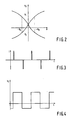
- Figs. 2, 3,4 illustrate the magnetization features of the magnetic field probe, the have form of the current driving an inversion coil included in the above probe and that of the voltage across the probe's output, respectively;
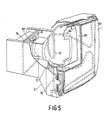
- Fig. 5 illustrates an embodiment of a picture tube with a compensation circuit according to the invention.
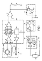
- With reference to Fig. 1, the circuit comprises a horizontal
magnetic field probe 6, a unit for processing the signal 7 and anamplifier 16 whose output controls a pair ofcompensation coils 15, arranged in series with one another, suitable for producing a component of an axial magnetic field opposite to that detected by theprobe 6. The output of theamplifier 16 also controls a pair ofdemagnetization coils 17, arranged in parallel to one another, suitable for producing, in combination with a screen to be described later, a component of a lateral magnetic field opposite to the lateral component of the external field. Between the output of theamplifier 16 and the pair ofdemagnetization coils 17 there is aunit 18 for the detection of variations of a magnetic field, acontrol unit 19 and ademagnetization circuit 20. - In particular, the
probe 6 comprises a bridge of fourresistances 1, 2, 3,4 and aninversion coil 5. The bridge (for example four resistances) comprises at least one magnetic field dependent resistance. The unit for processing the signal 7 comprises a preamplifier 8, on whose inputs there arecoupling condensers signal switching unit 9, whose inputs are represented by the output of the preamplifier 8 and by a reference signal Vref and whose outputs are connected to non-inverting and invertinginputs 13, 14 of adifferential amplifier 12. The unit for processing the signal 7 also comprises acontrol unit 10 constituted essentially by an impulse generator driven by the set's vertical synchronisation signal to send alternately positive and negative impulses to theinversion coil 5 through adriving circuit 11 and simultaneously to control the alternate closing and opening of two pairs ofswitches inputs 13, 14 of thedifferential amplifier 12. - The
unit 18 for the detection of variations of magnetic fields comprises a whole-haverectifier shunt 28 which receives at input the output signal of theamplifier 16, that is, a signal having a voltage proportional to the variation of the horizontal magnetic field, and produces an output which is compared to a reference voltage Vrif by means of acomparator 29 to produce, in the end, a control impulse for thecontrol unit 19. The latter is in turn constituted by abistable multivibrator 30 that controls thedemagnetization circuit 20 and by twotimers demagnetization circuit 20, while the second has the task of disactivating the output of thebistable multivibrator 30 for the time necessary for thedemagnetization circuit 20 to recharge, while also allowing the control impulse of thecircuit 20 to be memorized in it. Thedemagnetization circuit 20 comprises acomparator 48 which receives the control impulse of thecontrol unit 19 and apower stage 49 which supplies the twodemagnetization coils 17, as well as a feedback circuit which comprises a connectingcondenser 50 and a pair of parallel invertedconduction diodes comparator 48 is established. Thecomparator 48 receives power from a condenser 53 which discharges itself progressively and is periodically recharged by acurrent generator 55. - With reference to Fig. 5, the compensation circuit of Fig. 1 can be imagined to be applied to a
picture tube 60 provided with ascreen 63 and contained inside ashell 61. Inside it there is amask 62 with holes to direct the electronic beams towards the coloured phosphoruses on thescreen 63 and an internalmagnetic screen 64. There is also amagnetic probe 6, a pair of compensation coils 15, arranged concentrically at the two extremities of thepicture tube 60, suitable for producing an axial magnetic field and a pair of demagnetization coils 17 associated with the internalmagnetic screen 64 for producing a lateral magnetic field, as illustrated in Fig. 1. - The compensation circuit of Fig. 1 functions as follows.
- As illustrated in Fig. 2 the bridge circuit 1 - 4 has a pair of H-Vo characteristics (magnetic field detected in a produced voltage), which in themselves are a source of indetermination in relation to the sign of the variation detected in the horizontal magnetic field (Ho or -Ho).
- To overcome this drawback, as illustrated in Fig. 3, a succession of such alternately positive and negative impulses is sent by the
control unit 10 through the drivingcircuit 11 to theinversion coil 5. Such impulses have the task of forcing the bridge ofresistances 1, 2, 3, 4 to work alternately on one and on the other of the characteristics illustrated in Fig. 2. In this way at the output of theprobe 6 there is a square-wave signal, illustrated in Fig. 4, whose curve is representative of the value and of the sign of the magnetic field under test. Any offset of said output signal is cancelled by thecondensers - The impulses generated by the
control unit 10 determine the periodic operation ofswitches signal switching unit 9, which thus makes the comparison between the square-wave signal from theprobe 6, amplified by the preamplifier 8, and a reference signal Vref, applying the square-wave signal across thenon-inverting input 13 of thedifferential amplifier 12 and the reference signal across the inverting input 14 of thesame amplifier 12 when the square-wave signal has a positive sign and vice versa when the sign is negative. Such an operation has the effect of producing an output voltage that is continuous and proportional to the value of the magnetic field under test, which through theamplifier 16 shall supply the compensation coils 15 for the compensation of the axial magnetic field. - The signal from the
amplifier 16 also enters into theunit 18 for the detection of variations of a magnetic field, where every variation of the output voltage of theamplifier 16, through therectifier shunt 28 and thecomparator 29, where it is compared with a reference voltage Vrif, gives rise to a control impulse for thecontrol unit 19, where it is memorized in thebistable multivibrator 30 and sent to thedemagnetization circuit 20. Thetimer 32 feeds back thebistable multivibrator 30 and moves to disactivate the output of thebistable multivibrator 30 whenever it is necessary to allow thedemagnetization circuit 20 to recharge itself. It should be noted that the impulse to thebistable multivibrator 30 can also be controlled from the outside through asuitable switch 70. - The impulse from the
control unit 19 controls the oscillation of thedemagnetization circuit 20, Those duration is governed by the discharge time of the condenser 53, in turn charged by thecurrent generator 55. The control signal for thedemagnetization circuit 20 enters into the inverting input of thecomparator 48, which through thepower stage 49 sends into resonance the circuit consisting of the demagnetization coils 17 and thecondenser 50. The feedback signal is picked up across thediode parallel 51, 54 and applied across the non-inverting input of thecomparator 48. At the end of the discharge of the condenser 53 the oscillation of thecircuit 20 stops to start again when the next control impulse arrives from thecontrol unit 19.
Claims (11)
- Circuit for the compensation of the horizontal component of the earth's magnetic field for a colour picture tube of a picture display apparatus, characterised in that it includes a probe (6) for detecting a horizontal magnetic field and first and second circuit means (15, 17) driven by said probe (6) so as to create respective axial and lateral components of compensation of the horizontal magnetic field, that are of equal direction and intensity, but of opposite sign to that of the magnetic field under test.
- Circuit according to claim 1, characterised in that the first circuit means (15) comprise a pair of compensation coils (15) connected electrically in series and arranged concentrically with the axis of the picture tube (60) at its two extremities to produce said axial component of compensation of the magnetic field under test.
- Circuit according to Claim 1, characterised in that the said the second circuit means (17) comprise a pair of demagnetization coils (17) connected electrically in parallel and associated with an internal magnetic screen (64) applied to the picture tube (61) to produce said lateral component of compensation of the magnetic field under test.
- Circuit according to claim 3, characterised in that it comprises signal detection means (18) suitable for transforming the output of the probe (6) into a control impulse for a demagnetization circuit (20) formed by an oscillator (48, 49, 17, 50, 51, 52) including said demagnetization coils (17) and supplied from a rechargeable source of continuous voltage (53, 55).
- Circuit according to claim 1, characterized in that the probe comprises a bridge-circuit (1, 2, 3, 4) with at least one resistance which is magnetic field dependent and which bridge has a pair of H-Vo characteristics.
- Circuit according to Claim 5, characterized in that the probe comprises an inversion coil to force the bridge to work one or the other of the characteristics.
- Circuit according to claim 6 characterized in that the bridge is forced to work alternately in one and the other of the characteristics by impulses related to vertical synchronisation pulses.
- Circuit according to claim 3 characterized in that the unit for processing the signal comprises a preamplifier (8) with inputs to receive the signal from the probe and an output coupled to an input of a signal switching unit (9) at a second input the signal switching unit receives a reference voltage (Vref) and outputs of the signal switching unit are coupled with inputs of a differential amplifier (12).
- Circuit according to claim 8 characterized in that the signal switching unit comprises two pairs of switches (45, 47 and 44, 46) which select the signals transmitted to a non-inverting (13) and an inverting input (14) of the differential amplifier.
- Circuit according to claim 9 characterized in that the unit for processing the signal comprises a control unit having an input receiving a vertical synchronisation signal and a first output to control the alternating opening and closing of the two pairs of switches, and a second output to send alternately positive and negative impulses to the inversion coil (5) through a driving circuit (11) to force the bridge to work alternately in one and the other of the characteristics.
- Circuit according to claim 4 characterized in that the circuit comprises a control unit (19) for memorizing the control impulse and a first timer (31) for controlling the time to activate the demagnetization circuit (20) and a second timer (32) for controlling the time to disactivate the demagnetization circuit.
Priority Applications (1)
| Application Number | Priority Date | Filing Date | Title |
|---|---|---|---|
| EP95201774A EP0676901A3 (en) | 1990-06-08 | 1991-06-04 | Magnetic field detection circuit. |
Applications Claiming Priority (2)
| Application Number | Priority Date | Filing Date | Title |
|---|---|---|---|
| IT02059490A IT1248761B (en) | 1990-06-08 | 1990-06-08 | COMPENSATION CIRCUIT OF THE HORIZONTAL COMPONENT OF THE TERRESTRIAL MAGNETIC FIELD FOR CINESCOPE COLOR OF HIGH RESOLUTION MONITORS |
| IT2059490 | 1990-06-08 |
Related Child Applications (1)
| Application Number | Title | Priority Date | Filing Date |
|---|---|---|---|
| EP95201774.7 Division-Into | 1991-06-04 |
Publications (3)
| Publication Number | Publication Date |
|---|---|
| EP0460757A2 true EP0460757A2 (en) | 1991-12-11 |
| EP0460757A3 EP0460757A3 (en) | 1992-10-28 |
| EP0460757B1 EP0460757B1 (en) | 1997-01-08 |
Family
ID=11169305
Family Applications (2)
| Application Number | Title | Priority Date | Filing Date |
|---|---|---|---|
| EP95201774A Withdrawn EP0676901A3 (en) | 1990-06-08 | 1991-06-04 | Magnetic field detection circuit. |
| EP91201364A Expired - Lifetime EP0460757B1 (en) | 1990-06-08 | 1991-06-04 | Display device |
Family Applications Before (1)
| Application Number | Title | Priority Date | Filing Date |
|---|---|---|---|
| EP95201774A Withdrawn EP0676901A3 (en) | 1990-06-08 | 1991-06-04 | Magnetic field detection circuit. |
Country Status (7)
| Country | Link |
|---|---|
| US (1) | US5179315A (en) |
| EP (2) | EP0676901A3 (en) |
| JP (1) | JPH04233389A (en) |
| KR (1) | KR920001950A (en) |
| CA (1) | CA2043934C (en) |
| DE (1) | DE69124011T2 (en) |
| IT (1) | IT1248761B (en) |
Cited By (3)
| Publication number | Priority date | Publication date | Assignee | Title |
|---|---|---|---|---|
| EP0825785A2 (en) * | 1996-08-22 | 1998-02-25 | Thomson Consumer Electronics, Inc. | Discoloration band correction system |
| GB2317314A (en) * | 1996-09-13 | 1998-03-18 | Lg Electronics Inc | A purity adjustment device for a CRT display |
| WO1999022526A1 (en) * | 1997-10-24 | 1999-05-06 | Nagamori, Satoshi | Geomagnetic correction apparatus and television receiver employing the same |
Families Citing this family (4)
| Publication number | Priority date | Publication date | Assignee | Title |
|---|---|---|---|---|
| JPH07162882A (en) * | 1993-12-10 | 1995-06-23 | Sony Corp | Cathode-ray tube device |
| JP3541468B2 (en) * | 1994-12-15 | 2004-07-14 | ソニー株式会社 | Display device |
| KR0182920B1 (en) * | 1996-05-02 | 1999-10-01 | 김광호 | Image rotation automatic compensation circuit and its method |
| US8525514B2 (en) | 2010-03-19 | 2013-09-03 | Memsic, Inc. | Magnetometer |
Citations (8)
| Publication number | Priority date | Publication date | Assignee | Title |
|---|---|---|---|---|
| DE2146071A1 (en) * | 1971-09-15 | 1973-03-22 | Foerster Inst Dr Friedrich | ARRANGEMENT FOR ACHIEVING A SPACE FREE OF MAGNETIC INTERFERENCE FIELDS |
| US3757154A (en) * | 1971-03-03 | 1973-09-04 | Sony Corp | Magnetic field on color television receivers apparatus for automatically eliminating the influence of the earth s |
| EP0039502A1 (en) * | 1980-05-06 | 1981-11-11 | Siemens Aktiengesellschaft | Device for compensating outer magnetic fields acting on television colour picture tubes |
| JPS58107789A (en) * | 1981-12-22 | 1983-06-27 | Seiko Instr & Electronics Ltd | Automatic magnetism degaussor for video monitor |
| JPS58146190A (en) * | 1982-02-24 | 1983-08-31 | Nec Corp | Purity correction system of color receiver |
| JPS61289788A (en) * | 1985-06-17 | 1986-12-19 | Mitsubishi Electric Corp | Color cathode ray tube display device |
| JPS6239994A (en) * | 1985-08-14 | 1987-02-20 | Mitsubishi Electric Corp | Color cathode-ray tube device |
| EP0358133A2 (en) * | 1988-09-06 | 1990-03-14 | Thomson Consumer Electronics, Inc. | Magnetic field compensator for a CRT |
Family Cites Families (10)
| Publication number | Priority date | Publication date | Assignee | Title |
|---|---|---|---|---|
| FR1600004A (en) * | 1967-12-29 | 1970-07-20 | ||
| US3887833A (en) * | 1969-06-16 | 1975-06-03 | Hitachi Ltd | Color purity adjusting device for a color picture tube |
| JPS5137393Y2 (en) * | 1971-10-28 | 1976-09-13 | ||
| US3757174A (en) * | 1972-07-31 | 1973-09-04 | Sharp Kk | Light emitting four layer semiconductor |
| EP0065830A1 (en) * | 1981-05-07 | 1982-12-01 | EMI Limited | Magnetoresistive sensor arrangement |
| DE3267700D1 (en) * | 1981-09-09 | 1986-01-09 | Emi Ltd | Arrangements for resolving magnetic field components |
| US4380716A (en) * | 1981-10-09 | 1983-04-19 | Hazeltine Corporation | External magnetic field compensator for a CRT |
| DE3442278A1 (en) * | 1984-11-20 | 1986-05-22 | Philips Patentverwaltung Gmbh, 2000 Hamburg | Magnetic-field test set |
| US4636911A (en) * | 1984-11-30 | 1987-01-13 | Rca Corporation | Resonant degaussing for a video display system |
| US5036250A (en) * | 1988-06-14 | 1991-07-30 | U.S. Philips Corporation | Picture display device with core means comprising compensation coils |
-
1990
- 1990-06-08 IT IT02059490A patent/IT1248761B/en active IP Right Grant
-
1991
- 1991-06-03 US US07/709,678 patent/US5179315A/en not_active Expired - Fee Related
- 1991-06-04 EP EP95201774A patent/EP0676901A3/en not_active Withdrawn
- 1991-06-04 EP EP91201364A patent/EP0460757B1/en not_active Expired - Lifetime
- 1991-06-04 DE DE69124011T patent/DE69124011T2/en not_active Expired - Fee Related
- 1991-06-05 CA CA002043934A patent/CA2043934C/en not_active Expired - Fee Related
- 1991-06-06 JP JP3160837A patent/JPH04233389A/en active Pending
- 1991-06-07 KR KR1019910009413A patent/KR920001950A/en active IP Right Grant
Patent Citations (8)
| Publication number | Priority date | Publication date | Assignee | Title |
|---|---|---|---|---|
| US3757154A (en) * | 1971-03-03 | 1973-09-04 | Sony Corp | Magnetic field on color television receivers apparatus for automatically eliminating the influence of the earth s |
| DE2146071A1 (en) * | 1971-09-15 | 1973-03-22 | Foerster Inst Dr Friedrich | ARRANGEMENT FOR ACHIEVING A SPACE FREE OF MAGNETIC INTERFERENCE FIELDS |
| EP0039502A1 (en) * | 1980-05-06 | 1981-11-11 | Siemens Aktiengesellschaft | Device for compensating outer magnetic fields acting on television colour picture tubes |
| JPS58107789A (en) * | 1981-12-22 | 1983-06-27 | Seiko Instr & Electronics Ltd | Automatic magnetism degaussor for video monitor |
| JPS58146190A (en) * | 1982-02-24 | 1983-08-31 | Nec Corp | Purity correction system of color receiver |
| JPS61289788A (en) * | 1985-06-17 | 1986-12-19 | Mitsubishi Electric Corp | Color cathode ray tube display device |
| JPS6239994A (en) * | 1985-08-14 | 1987-02-20 | Mitsubishi Electric Corp | Color cathode-ray tube device |
| EP0358133A2 (en) * | 1988-09-06 | 1990-03-14 | Thomson Consumer Electronics, Inc. | Magnetic field compensator for a CRT |
Non-Patent Citations (4)
| Title |
|---|
| PATENT ABSTRACTS OF JAPAN vol. 11, no. 154 (E-508)19 May 1987 & JP-A-61 289 788 ( MITSUBISHI ) * |
| PATENT ABSTRACTS OF JAPAN vol. 11, no. 220 (E-524)16 July 1987 & JP-A-62 039 994 ( MITSUBISHI ) * |
| PATENT ABSTRACTS OF JAPAN vol. 7, no. 214 (E-199)(1359) 21 September 1983 & JP-A-58 107 789 ( SEIKO ) * |
| PATENT ABSTRACTS OF JAPAN vol. 7, no. 264 (E-212)(1409) 24 November 1983 & JP-A-58 146 190 ( NIPPON DENKI K.K. ) * |
Cited By (6)
| Publication number | Priority date | Publication date | Assignee | Title |
|---|---|---|---|---|
| EP0825785A2 (en) * | 1996-08-22 | 1998-02-25 | Thomson Consumer Electronics, Inc. | Discoloration band correction system |
| EP0825785A3 (en) * | 1996-08-22 | 1999-04-14 | Thomson Consumer Electronics, Inc. | Discoloration band correction system |
| GB2317314A (en) * | 1996-09-13 | 1998-03-18 | Lg Electronics Inc | A purity adjustment device for a CRT display |
| GB2317314B (en) * | 1996-09-13 | 1998-12-30 | Lg Electronics Inc | Purity adjustment device for video display appliance |
| US6246448B1 (en) | 1996-09-13 | 2001-06-12 | L.G. Electronics, Inc. | Purity adjustment device for video display appliance |
| WO1999022526A1 (en) * | 1997-10-24 | 1999-05-06 | Nagamori, Satoshi | Geomagnetic correction apparatus and television receiver employing the same |
Also Published As
| Publication number | Publication date |
|---|---|
| JPH04233389A (en) | 1992-08-21 |
| EP0676901A2 (en) | 1995-10-11 |
| EP0460757B1 (en) | 1997-01-08 |
| DE69124011T2 (en) | 1997-06-19 |
| US5179315A (en) | 1993-01-12 |
| KR920001950A (en) | 1992-01-30 |
| IT9020594A1 (en) | 1991-12-08 |
| CA2043934C (en) | 2002-02-12 |
| IT1248761B (en) | 1995-01-27 |
| EP0676901A3 (en) | 1997-07-16 |
| IT9020594A0 (en) | 1990-06-08 |
| CA2043934A1 (en) | 1991-12-09 |
| EP0460757A3 (en) | 1992-10-28 |
| DE69124011D1 (en) | 1997-02-20 |
Similar Documents
| Publication | Publication Date | Title |
|---|---|---|
| US4963789A (en) | Method and apparatus for dynamic magnetic field neutralization | |
| US4485394A (en) | Automatic convergence and gray scale correction for television _receivers and projection television systems | |
| US5179315A (en) | Circuit for the compensation of the horizontal component of the earth's magnetic field for a color picture tube of a high-resolution monitor | |
| US7330164B2 (en) | Video controlled detector sensitivity | |
| DK147330B (en) | METHOD OF MAGNETIZING PROCEDURE AND APPARATUS TO ACHIEVE STATIC CONVERGENCE IN A COTTON RADIATION | |
| JPS6132778B2 (en) | ||
| US5367221A (en) | Magnetic immunity system (MIS) and monitor incorporating the MIS | |
| KR0144731B1 (en) | Magnetic field compensator for a crt | |
| US5604403A (en) | Color monitor magnetic shield | |
| JPH0411076B2 (en) | ||
| US4580078A (en) | Method of adjusting color purity in a television receiver, and television receiver with purity-adjustment system | |
| JPS6030155B2 (en) | Convergence automatic adjustment device | |
| GB818669A (en) | Presentation of coloured television pictures | |
| US3737716A (en) | Color purity adjustment utilizing a coil attached to the faceplate | |
| US2806978A (en) | Alignment of television camera tubes | |
| SU1345149A1 (en) | Device for magnetizing,demagnetizing and checking magnetic field intensity of articles | |
| JPS59148484A (en) | Degaussing device of color receiver | |
| US7286175B1 (en) | Bias control circuitry for cathode ray tube beam currents | |
| KR19990082246A (en) | Apparatus and process for magnetizing the magnetic ring for static convergence correction in cathode ray tubes | |
| JP2845906B2 (en) | Apparatus and method for measuring color purity | |
| KR920010374B1 (en) | Method of controlling convergence | |
| US6635994B1 (en) | Method and apparatus for demagnetizing color CRT | |
| JPH0156594B2 (en) | ||
| JP3250287B2 (en) | Method and apparatus for measuring displacement of beam spot of cathode ray tube | |
| KR910010118B1 (en) | Degaussing circuit using d.c. power |
Legal Events
| Date | Code | Title | Description |
|---|---|---|---|
| PUAI | Public reference made under article 153(3) epc to a published international application that has entered the european phase |
Free format text: ORIGINAL CODE: 0009012 |
|
| AK | Designated contracting states |
Kind code of ref document: A2 Designated state(s): DE FR GB IT |
|
| PUAL | Search report despatched |
Free format text: ORIGINAL CODE: 0009013 |
|
| AK | Designated contracting states |
Kind code of ref document: A3 Designated state(s): DE FR GB IT |
|
| 17P | Request for examination filed |
Effective date: 19930421 |
|
| 17Q | First examination report despatched |
Effective date: 19931112 |
|
| GRAG | Despatch of communication of intention to grant |
Free format text: ORIGINAL CODE: EPIDOS AGRA |
|
| RTI1 | Title (correction) | ||
| GRAH | Despatch of communication of intention to grant a patent |
Free format text: ORIGINAL CODE: EPIDOS IGRA |
|
| GRAH | Despatch of communication of intention to grant a patent |
Free format text: ORIGINAL CODE: EPIDOS IGRA |
|
| GRAA | (expected) grant |
Free format text: ORIGINAL CODE: 0009210 |
|
| AK | Designated contracting states |
Kind code of ref document: B1 Designated state(s): DE FR GB IT |
|
| XX | Miscellaneous (additional remarks) |
Free format text: TEILANMELDUNG 95201774.7 EINGEREICHT AM 04/06/91. |
|
| REF | Corresponds to: |
Ref document number: 69124011 Country of ref document: DE Date of ref document: 19970220 |
|
| ITF | It: translation for a ep patent filed | ||
| ET | Fr: translation filed | ||
| PLBE | No opposition filed within time limit |
Free format text: ORIGINAL CODE: 0009261 |
|
| STAA | Information on the status of an ep patent application or granted ep patent |
Free format text: STATUS: NO OPPOSITION FILED WITHIN TIME LIMIT |
|
| 26N | No opposition filed | ||
| REG | Reference to a national code |
Ref country code: FR Ref legal event code: CD |
|
| PGFP | Annual fee paid to national office [announced via postgrant information from national office to epo] |
Ref country code: FR Payment date: 20010625 Year of fee payment: 11 |
|
| PGFP | Annual fee paid to national office [announced via postgrant information from national office to epo] |
Ref country code: GB Payment date: 20010629 Year of fee payment: 11 |
|
| PGFP | Annual fee paid to national office [announced via postgrant information from national office to epo] |
Ref country code: DE Payment date: 20010821 Year of fee payment: 11 |
|
| REG | Reference to a national code |
Ref country code: GB Ref legal event code: IF02 |
|
| PG25 | Lapsed in a contracting state [announced via postgrant information from national office to epo] |
Ref country code: GB Free format text: LAPSE BECAUSE OF NON-PAYMENT OF DUE FEES Effective date: 20020604 |
|
| PG25 | Lapsed in a contracting state [announced via postgrant information from national office to epo] |
Ref country code: DE Free format text: LAPSE BECAUSE OF NON-PAYMENT OF DUE FEES Effective date: 20030101 |
|
| GBPC | Gb: european patent ceased through non-payment of renewal fee |
Effective date: 20020604 |
|
| PG25 | Lapsed in a contracting state [announced via postgrant information from national office to epo] |
Ref country code: FR Free format text: LAPSE BECAUSE OF NON-PAYMENT OF DUE FEES Effective date: 20030228 |
|
| REG | Reference to a national code |
Ref country code: FR Ref legal event code: ST |
|
| PG25 | Lapsed in a contracting state [announced via postgrant information from national office to epo] |
Ref country code: IT Free format text: LAPSE BECAUSE OF NON-PAYMENT OF DUE FEES;WARNING: LAPSES OF ITALIAN PATENTS WITH EFFECTIVE DATE BEFORE 2007 MAY HAVE OCCURRED AT ANY TIME BEFORE 2007. THE CORRECT EFFECTIVE DATE MAY BE DIFFERENT FROM THE ONE RECORDED. Effective date: 20050604 |