EP0460595A2 - Apparatus for correcting a black level of a video signal - Google Patents
Apparatus for correcting a black level of a video signal Download PDFInfo
- Publication number
- EP0460595A2 EP0460595A2 EP91109094A EP91109094A EP0460595A2 EP 0460595 A2 EP0460595 A2 EP 0460595A2 EP 91109094 A EP91109094 A EP 91109094A EP 91109094 A EP91109094 A EP 91109094A EP 0460595 A2 EP0460595 A2 EP 0460595A2
- Authority
- EP
- European Patent Office
- Prior art keywords
- black
- level
- signal
- circuit
- luminance
- Prior art date
- Legal status (The legal status is an assumption and is not a legal conclusion. Google has not performed a legal analysis and makes no representation as to the accuracy of the status listed.)
- Granted
Links
Images

Classifications
-
- H—ELECTRICITY
- H04—ELECTRIC COMMUNICATION TECHNIQUE
- H04N—PICTORIAL COMMUNICATION, e.g. TELEVISION
- H04N9/00—Details of colour television systems
- H04N9/77—Circuits for processing the brightness signal and the chrominance signal relative to each other, e.g. adjusting the phase of the brightness signal relative to the colour signal, correcting differential gain or differential phase
-
- H—ELECTRICITY
- H04—ELECTRIC COMMUNICATION TECHNIQUE
- H04N—PICTORIAL COMMUNICATION, e.g. TELEVISION
- H04N9/00—Details of colour television systems
- H04N9/64—Circuits for processing colour signals
- H04N9/72—Circuits for processing colour signals for reinsertion of DC and slowly varying components of colour signals
-
- H—ELECTRICITY
- H04—ELECTRIC COMMUNICATION TECHNIQUE
- H04N—PICTORIAL COMMUNICATION, e.g. TELEVISION
- H04N9/00—Details of colour television systems
- H04N9/64—Circuits for processing colour signals
- H04N9/68—Circuits for processing colour signals for controlling the amplitude of colour signals, e.g. automatic chroma control circuits
Abstract
Description
- This invention relates to an apparatus for correcting a black level of a video signal.
- In the field of color television receivers, there are various apparatuses for correcting a color-tone component of a video signal to widen the dynamic range of a reproduced color image and thereby to clarify the reproduced color image. Some of such color-tone correcting apparatuses have a non-linear amplifier for processing a video signal. Black-level correcting apparatuses are of one type of such color-tone correcting apparatuses. As will be explained later, a prior art black-level correcting apparatus has some problem.
- It is an object of this invention to provide an improved apparatus for correcting a black level of a video signal.
- According to a first aspect of this invention, an apparatus for correcting a black level of a video signal comprises pedestal clamping means for clamping a pedestal level of an input video signal in response to a predetermined pedestal voltage, and converting the input video signal into a clamped video signal; black-level expanding means for expanding a tone of a black portion of the clamped video signal, and converting the clamped video signal into a black-level expanded video signal; color greatest detecting means for detecting a greatest of color signals of the input video signal; adding means for adding an output signal from the color greatest detecting means and the pedestal voltage; and black-level comparing means, responsive to the black-level expanded video signal and an output signal from the adding means, for detecting a blackest portion of the black-level expanded video signal, comparing the detected blackest portion of the black-level expanded video signal with the output signal from the adding means, and controlling a degree of expanding the black tone by the black-level expanding means in response to a difference between the detected blackest portion of the black-level expanded video signal and the output signal from the adding means.
- According to a second aspect of this invention, an apparatus for correcting a black level of a video signal comprises a pedestal clamp circuit for clamping a pedestal level of an input luminance signal in response to a predetermined pedestal voltage, and converting the input luminance signal into a clamped luminance signal; a black-level expanding circuit for expanding a tone of a black portion of the clamped luminance signal, and converting the clamped luminance signal into a black-level expanded luminance signal; a color greatest detecting circuit for detecting a greatest of input color difference signals; a level limiting circuit for limiting a level of an output signal from the color greatest detecting circuit to within a predetermined range; a gain control circuit for controlling an amplitude of an output signal from the level limiting circuit; an adding circuit for adding an output signal from the gain control circuit and the pedestal voltage; and a black-level comparing circuit, responsive to the black-level expanded luminance signal and an output signal from the adding circuit, for detecting a blackest portion of the black-level expanded luminance signal, comparing the detected blackest portion of the black-level expanded luminance signal with the output signal from the adding circuit, and controlling a degree of expanding the black tone by the black-level expanding circuit in response to a difference between the detected blackest portion of the black-level expanded luminance signal and the output signal from the adding circuit.
- According to a third aspect of this invention, an apparatus for correcting a black level of a video signal comprises a pedestal clamp circuit for clamping a pedestal level of an input luminance signal in response to a predetermined pedestal voltage, and converting the input luminance signal into a clamped luminance signal; a black-level expanding circuit for expanding a tone of a black portion of the clamped luminance signal, and converting the clamped luminance signal into a black-level expanded luminance signal; an average luminance level detecting circuit for detecting an average luminance level of the black-level expanded luminance signal, and outputting an average luminance detection signal representative thereof; a gain control circuit for controlling an amplitude of the average luminance detection signal; an adding circuit for adding an output signal from the gain control circuit and the pedestal voltage; and a black-level comparing circuit, responsive to the black-level expanded luminance signal and an output signal from the adding circuit, for detecting a blackest portion of the black-level expanded luminance signal, comparing the detected blackest portion of the black-level expanded luminance signal with the output signal from the adding circuit, and controlling a degree of expanding the black tone by the black-level expanding circuit in response to a difference between the detected blackest portion of the black-level expanded luminance signal and the output signal from the adding circuit.
- According to a fourth aspect of this invention, an apparatus for correcting a black level of a video signal comprises a pedestal clamp circuit for clamping a pedestal level of an input luminance signal in response to a predetermined pedestal voltage, and converting the input luminance signal into a clamped luminance signal; a black-level expanding circuit for expanding a tone of a black portion of the clamped luminance signal, and converting the clamped luminance signal into a black-level expanded luminance signal; a color detection matrix circuit for detecting a predetermined-color portion in response to an input color difference signal; a gain control circuit for controlling an amplitude of an output signal from the color detection matrix circuit; an adding circuit for adding an output signal from the gain control circuit and the pedestal voltage; and a black-level comparing circuit, responsive to the black-level expanded luminance signal and an output signal from the adding circuit, for detecting a blackest portion of the black-level expanded luminance signal, comparing the detected blackest portion of the black-level expanded luminance signal with the output signal from the adding circuit, and controlling a degree of expanding the black tone by the black-level expanding circuit in response to a difference between the detected blackest portion of the black-level expanded luminance signal and the output signal from the adding circuit.
- According to a fifth aspect of this invention, an apparatus for correcting a black level of a video signal comprises a pedestal clamp circuit for clamping a pedestal level of an input luminance signal in response to a predetermined pedestal voltage, and converting the input luminance signal into a clamped luminance signal; a black-level expanding circuit for expanding a tone of a black portion of the clamped luminance signal, and converting the clamped luminance signal into a black-level expanded luminance signal; a color detection matrix circuit for detecting a predetermined-color portion in response to an input color demodulation signal; a gain control circuit for controlling an amplitude of an output signal from the color detection matrix circuit; an adding circuit for adding an output signal from the gain control circuit and the pedestal voltage; and a black-level comparing circuit, responsive to the black-level expanded luminance signal and an output signal from the adding circuit, for detecting a blackest portion of the black-level expanded luminance signal, comparing the detected blackest portion of the black-level expanded luminance signal with the output signal from the adding circuit, and controlling a degree of expanding the black tone by the black-level expanding circuit in response to a difference between the detected blackest portion of the black-level expanded luminance signal and the output signal from the adding circuit.
- According to a sixth aspect of this invention, in an apparatus for controlling a black level of luminance components of a video signal with respect to a reference level in a closed-loop control, the improvement comprises means for detecting whether or not an image represented by the video signal has a color different from a black-and-white color, and outputting a detection signal representative thereof; and means for varying the reference level in response to the detection signal.
- According to a seventh aspect of this invention, in an apparatus for controlling a black level of luminance components of a video signal with respect to a reference level in a closed-loop control, the improvement comprises means for detecting an average of levels of the luminance components of the video signal, and outputting a detection signal representative thereof; and means for varying the reference level in response to the detection signal.
- According to an eighth aspect of this invention, in an apparatus for controlling a black level of luminance components of a video signal with respect to a reference level in a closed-loop control, the improvement comprises means for detecting a component of the video signal which corresponds to a predetermined color different from a black-and-white color, and outputting a detection signal representative thereof; and means for varying the reference level in response to the detection signal.
- Fig. 1 is a block diagram of a prior art black-level correcting apparatus.
- Fig. 2 is a time-domain diagram showing the waveforms of signals in the prior art black-level correcting apparatus of Fig. 1.
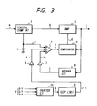
- Fig. 3 is a block diagram of a black-level correcting apparatus according to a first embodiment of this invention.
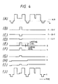
- Fig. 4 is a time-domain diagram showing the waveforms of various signals in the black-level correcting apparatus of Fig. 3.
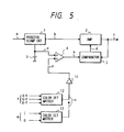
- Fig. 5 is a block diagram of a black-level correcting apparatus according to a second embodiment of this invention.
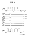
- Fig. 6 is a time-domain diagram showing the waveforms of various signals in the black-level correcting apparatus of Fig. 5.
- As shown in Fig. 1, a prior art black-level correcting apparatus includes a
pedestal clamping circuit 1, a variable-gain amplifier 2, and a black-level comparator 3. - The
pedestal clamping circuit 1 receives an input luminance signal "a" which has a waveform such as shown in the part (A) of Fig. 2. Thepedestal clamping circuit 1 receives a predetermined pedestal voltage "e" from adc voltage source 5. Thepedestal clamping circuit 1 subjects the input luminance signal "a" to a clamping process responsive to the pedestal voltage "e", and converts the input luminance signal "a" into a clamped luminance signal "b". The clamped luminance signal "b" has a waveform such as shown in the part (A) of Fig. 2. - The
amplifier 2 receives the clamped luminance signal "b" from thepedestal clamping circuit 1. Theamplifier 2 receives a control signal "d" from the black-level comparator 3. Theamplifier 2 expands the tone of a black portion of the clamped luminance signal "b" in response to the control signal "d", and converts the clamped luminance signal "b" into an output luminance signal "c". The output luminance signal "c" has a waveform such as shown in the part (B) of Fig. 2. The gain of theamplifier 2 is determined by the control signal "d", so that the degree of the expansion of the black tone depends on the control signal "d". - The black-
level comparator 3 receives the output luminance signal "c" from theamplifier 2. The black-level comparator 3 receives the pedestal voltage "e" from thedc voltage source 5. The black-level comparator 3 has a composite structure, including a black-level detector and a comparing section. The black-level detector detects the lowest level of a picture information part of the output luminance signal "c", that is, the level of the darkest picture information segment of the output luminance signal "c". The comparing section compares the detected level of the darkest picture information segment of the output luminance signal "c" with the pedestal voltage "e", and generates the control signal "d" in response to the result of the comparison. - The
amplifier 2 and the black-level comparator 3 cooperate to subject the black level of the output luminance signal "c" to a closed-loop control responsive to the pedestal voltage "e". This closed-loop control is designed so that the black level of the output luminance signal "c" can be equal to the pedestal voltage "e" or held at and below a predetermined reference level. - The prior art black-level correcting apparatus of Fig. 1 has the following over-control problems. Since the black level of a video signal is controlled in response to only luminance components thereof, a dark portion of a corresponding reproduced image which has a color different from a black-and-white color is changed in luminance but is unchanged in color so that the dark portion tends to be appreciably different from the original. Especially, a portion of a reproduced image which has a typical skin color of the yellow race tends to be darker undesirably. Furthermore, in the case of a video signal having a high average luminance, that is, in the case of a video signal representing a bright image, dark portions of a corresponding reproduced image tend to be equally blacked so that the details of the dark portions tend to be unseen.
- With reference to Fig. 3, a black-level correcting apparatus of a first embodiment of this invention includes a
pedestal clamping circuit 1, a variable-gain amplifier 2, a black-level comparator 3, an adder or asumming circuit 4, adc voltage source 5,gain control circuits 6 and 7, anaverage level detector 8, a clipping and limitingcircuit 9, and agreatest detector 10. - The
pedestal clamping circuit 1 receives an input luminance signal "a" which has a waveform such as shown in the part (A) of Fig. 4. Thepedestal clamping circuit 1 receives a predetermined pedestal voltage "e" from thedc voltage source 5. Thepedestal clamping circuit 1 subjects the input luminance signal "a" to a clamping process responsive to the pedestal voltage "e", and converts the input luminance signal "a" into a clamped luminance signal "b". The clamped luminance signal "b" has a waveform such as shown in the part (A) of Fig. 4. - The
amplifier 2 receives the clamped luminance signal "b" from thepedestal clamping circuit 1. Theamplifier 2 receives a control signal "d" from the black-level comparator 3. Theamplifier 2 expands the tone of a black portion of the clamped luminance signal "b" in response to the control signal "d", and converts the clamped luminance signal "b" into an output luminance signal "c". The output luminance signal "c" has a waveform such as shown in the part (J) of Fig. 4. The gain of theamplifier 2 is determined by the control signal "d", so that the degree of the expansion of the black tone depends on the control signal "d". - The black-
level comparator 3 receives the output luminance signal "c" from theamplifier 2. The black-level comparator 3 receives the output signal "s" from theadder 4. As will be made clear later, the output signal "s" from theadder 4 depends on the pedestal voltage "e", an average level of the output luminance signal "c", and a greatest color difference signal "g". The output signal "s" from theadder 4 has a waveform such as shown in the part (I) of Fig. 4. The black-level comparator 3 has a composite structure, including a black-level detector and a comparing section. The black-level detector detects the lowest level of a picture information part of the output luminance signal "c", that is, the level of the darkest picture information segment of the output luminance signal "c". The comparing section compares the detected level of the darkest picture information segment of the output luminance signal "c" with the level of the output signal "s" from theadder 4, and generates the control signal "d" in response to the result of the comparison. - The
amplifier 2 and the black-level comparator 3 cooperate to subject the black level of the output luminance signal "c" to a closed-loop control responsive to the pedestal voltage "e", the average level of the output luminance signal "c", and the greatest color difference signal "g". - The
average level detector 8 receives the output luminance signal "c" from theamplifier 2. Theaverage level detector 8 detects the average level of the picture information part of the output luminance signal "c", and outputs a signal "j" with a level corresponding to the detected average level of the output luminance signal "c". The gain control circuit 7 receives the average luminance level signal "j" from theaverage level detector 8. The gain control circuit 7 controls the amplitude of the average luminance level signal "j", and converts the average luminance level signal "j" into a second average luminance level signal "k". The second average luminance level signal "k" has a waveform such as shown in the part (H) of Fig. 4. - A group "f" of three color difference signals R-Y, G-Y, and B-Y is inputted into the
greatest detector 10. Thegreatest detector 10 detects the greatest of the three color difference signals R-Y, G-Y, and B-Y, and selects the greatest color difference signal and outputs the selected color difference signal "g". For example, when the levels of the three color difference signals R-Y, G-Y, and B-Y increase and decrease as shown in the parts (B)-(D) of Fig. 4, the greatest color difference signal "g" varies as shown in the part (E) of Fig. 4. - The clipping and limiting
circuit 9 receives the greatest color difference signal "g" from thegreatest detector 10. The clipping and limitingcircuit 9 has a composite structure, including a clipping section and a limiting section which are connected in series. The clipping section clips the greatest color difference signal "g" with a predetermined clipping level. Specifically, the clipping section transmits the greatest color difference signal "g" which has a level equal to or greater than the clipping level, but cuts off the greatest color difference signal "g" which has a level below the clipping level. In this way, the clipping section cuts off the small-amplitude components of the greatest color difference signal "g". Cutting off the small-amplitude components of the greatest color difference signal "g" suppresses or decreases noise components of the greatest color difference signal "g". The limiting section limits the amplitude of the greatest color difference signal "g" to within a predetermined amplitude, and thereby prevents the amplitude of the greatest color difference signal "g" from exceeding a predetermined limiting level. As a result, the clipping and limitingcircuit 9 confines the level of the greatest color difference signal "g" to a given range between an upper limit and a lower limit determined by the limiting level and the clipping level respectively. Thus, the clipping and limitingcircuit 9 converts the greatest color difference signal "g" into a level-confined color difference signal "h". For example, when the level of the greatest color difference signal "g" varies around the limiting level and the clipping level as shown in the part (E) of Fig. 4, the output color difference signal "h" from the clipping and limitingcircuit 9 varies as shown in the part (F) of Fig. 4. Thegain control circuit 6 receives the color difference signal "h" from the clipping and limitingcircuit 9. Thegain control circuit 6 controls the amplitude of the color difference signal "h", and converts the color difference signal "h" into an amplitude-controlled color difference signal "i". For example, when the level of the color difference signal "h" varies as shown in the part (F) of Fig. 4, the level of the color difference signal "i" varies as shown in the part (G) of Fig. 4. - The
adder 4 receives the pedestal voltage "e" from thedc voltage source 5. Theadder 4 receives the average luminance level signal "k" from the gain control circuit 7. Theadder 4 receives the color difference signal "i" from thegain control circuit 6. Theadder 4 sums the levels of the received signals "e", "k", and "i", and combines the signals "e", "k", and "i" into the output signal "s". Thus, the output signal "s" from theadder 4 depends on the pedestal voltage "e", the average level of the output luminance signal "c", and the color difference signal "i" which originates from the greatest color difference signal "g". - The output signal "s" from the
adder 4 is fed to the black-level comparator 3. As described previously, theamplifier 2 and the black-level comparator 3 cooperate to subject the black level of the output luminance signal "c" to a closed-loop control responsive to the output signal "s" from theadder 4 which depends on the pedestal voltage "e", the average level of the output luminance signal "c", and the greatest color difference signal "g". This closed-loop control is basically designed so that the black level of the output luminance signal "c" will be held at or near the pedestal voltage "e". In addition, the closed-loop control is designed so that the degree of the expansion of the black level of the output signal "c" will be decreased when the average level of the output luminance signal "c" is high as shown in Fig. 4. Therefore, in the case of a video signal having a high average luminance, that is, in the case of a video signal representing a bright image, dark portions of a corresponding reproduced image are prevented from being equally blacked so that the details of the dark portions can be seen. Furthermore, the closed-loop control is designed so that the degree of the expansion of the black level of the output signal "c" will be decreased when the greatest color difference signal "g" has an appreciable level. The closed-loop control responsive to the greatest color difference signal "g" will be described further. The level of the greatest color difference signal "g" outputted from thegreatest detector 10 is minimized when a corresponding part of a reproduced image has a black-and-white color (a gray color). The level of the greatest color difference signal "g" is larger than the minimal level when a corresponding part of a reproduced image has a color different from a black-and-white color (a gray color). The greatest color difference signal "g" is processed by the clipping and limitingcircuit 9 so that small-level noise components can be removed from the greatest color difference signal "g", and that the correction of the black level will be prevented from being excessively reduced when the greatest color difference signal "g" has a large level. The color difference signal outputted from the clipping and limitingcircuit 9 is transmitted to the black-level comparator 3 via thegain control circuit 6 and theadder 4. As a result, the degree of the expansion of the black level of the output signal "c" will be decreased when the greatest color difference signal has an appreciable level, that is, when a corresponding part of a reproduced image has a color appreciably different from a black-and-white color (a gray color). Thus, a dark portion of a corresponding reproduced image which has a color different from a black-and-white color is prevented from undesirably changing in luminance. Especially, a portion of a reproduced image which has a typical skin color of the yellow race is prevented from being darker undesirably. - It should be noted that the
pedestal clamping circuit 1 may be replaced by a sync top clamping circuit. - With reference to Fig. 5, a black-level correcting apparatus of a second embodiment of this invention includes a
pedestal clamping circuit 1, a variable-gain amplifier 2, a black-level comparator 3, an adder or a summingcircuit 4, adc voltage source 5, again control circuit 11, and colordetection matrix circuits - The
pedestal clamping circuit 1 receives an input luminance signal "a" which has a waveform such as shown in the part (A) of Fig. 6. Thepedestal clamping circuit 1 receives a predetermined pedestal voltage "e" from thedc voltage source 5. Thepedestal clamping circuit 1 subjects the input luminance signal "a" to a clamping process responsive to the pedestal voltage "e", and converts the input luminance signal "a" into a clamped luminance signal "b". The clamped luminance signal "b" has a waveform such as shown in the part (A) of Fig. 6. - The
amplifier 2 receives the clamped luminance signal "b" from thepedestal clamping circuit 1. Theamplifier 2 receives a control signal "d" from the black-level comparator 3. Theamplifier 2 expands the tone of a black portion of the clamped luminance signal "b" in response to the control signal "d", and converts the clamped luminance signal "b" into an output luminance signal "c". The output luminance signal "c" has a waveform such as shown in the part (H) of Fig. 6. The gain of theamplifier 2 is determined by the control signal "d", so that the degree of the expansion of the black tone depends on the control signal "d". - The black-
level comparator 3 receives the output luminance signal "c" from theamplifier 2. The black-level comparator 3 receives the output signal "s" from theadder 4. As will be made clear later, the output signal "s" from theadder 4 depends on the pedestal voltage "e" and a predetermined-color detection signal. The output signal "s" from theadder 4 has a waveform such as shown in the part (G) of Fig. 6. The black-level comparator 3 has a composite structure, including a black-level detector and a comparing section. The black-level detector detects the lowest level of a picture information part of the output luminance signal "c", that is, the level of the darkest picture information segment of the output luminance signal "c". The comparing section compares the detected level of the darkest picture information segment of the output luminance signal "c" with the level of the output signal "s" from theadder 4, and generates the control signal "d" in response to the result of the comparison. - The
amplifier 2 and the black-level comparator 3 cooperate to subject the black level of the output luminance signal "c" to a closed-loop control responsive to the pedestal voltage "e" and a predetermined-color detection signal. - A group "f" of three color difference signals R-Y, G-Y, and B-Y is inputted into the color
detection matrix circuit 12. The colordetection matrix circuit 12 detects a predetermined-color signal component in response to at least two of the color difference signals R-Y, G-Y, and B-Y. Specifically, the predetermined color is chosen so as to agree with a typical skin color of the yellow race. For example, the colordetection matrix circuit 12 detects the predetermined-color signal component "n" in response to the color difference signals R-Y and B-Y by referring to the following equation.

where "x" denotes an operator of production. The colordetection matrix circuit 12 outputs a signal "n" representing the detected color signal component. For example, when the levels of the three color difference signals R-Y, G-Y, and B-Y increase and decrease as shown in the parts (B)-(D) of Fig. 6, the color detection signal "n" varies as shown in the part (E) of Fig. 6. - A group "m" of two color signals "I" and "Q" is inputted into the color
detection matrix circuit 13. The colordetection matrix circuit 13 detects a predetermined-color signal component in response to the color signals "I" and "Q". Specifically, the predetermined color is chosen so as to agree with a typical skin color of the yellow race. The colordetection matrix circuit 13 outputs a signal "n" representing the detected color signal component. - One of the color
detection matrix circuits - The
gain control circuit 11 receives the color detection signal "n" from the colordetection matrix circuit 12 or the colordetection matrix circuit 13. Thegain control circuit 11 controls the amplitude of the color detection signal "n", and converts the color detection signal "n" into an amplitude-controlled color detection signal "p". For example, when the level of the color detection signal "n" varies as shown in the part (E) of Fig. 6, the level of the color detection signal "p" varies as shown in the part (F) of Fig. 6. - The
adder 4 receives the pedestal voltage "e" from thedc voltage source 5. Theadder 4 receives the color detection signal "p" from thegain control circuit 11. Theadder 4 sums the levels of the received signals "e" and "p", and combines the signals "e" and "p" into the output signal "s". Thus, the output signal "s" from theadder 4 depends on the pedestal voltage "e" and the color detection signal "p". - The output signal "s" from the
adder 4 is fed to the black-level comparator 3. As described previously, theamplifier 2 and the black-level comparator 3 cooperate to subject the black level of the output luminance signal "c" to a closed-loop control responsive to the output signal "s" from theadder 4 which depends on the pedestal voltage "e" and the color detection signal "s". This closed-loop control is basically designed so that the black level of the output luminance signal "c" will be held at or near the pedestal voltage "e". In addition, the closed-loop control is designed so that the degree of the expansion of the black level of the output signal "c" will be decreased when the color detection signal "p" has an appreciable level, that is, when a corresponding part of a reproduced image has a color essentially equal to the predetermined color detected by the colordetection matrix circuit - It should be noted that the
pedestal clamping circuit 1 may be replaced by a sync top clamping circuit. - A pedestal clamping device clamps a pedestal level of an input video signal in response to a predetermined pedestal voltage, and converts the input video signal into a clamped video signal. A black-level expanding device expands a tone of a black portion of the clamped video signal, and converts the clamped video signal into a black-level expanded video signal. A color greatest detecting device detects a greatest of color signals of the input video signal. A adding device adds an output signal from the color greatest detecting device and the pedestal voltage. A black-level comparing device detects a blackest portion of the black-level expanded video signal; compares the detected blackest portion of the black-level expanded video signal with the output signal from the adding device; and controls a degree of expanding the black tone by the black-level expanding device in response to a difference between the detected blackest portion of the black-level expanded video signal and the output signal from the adding device.
Claims (10)
- An apparatus for correcting a black level of a video signal, comprising:
pedestal clamping means for clamping a pedestal level of an input video signal in response to a predetermined pedestal voltage, and converting the input video signal into a clamped video signal;
black-level expanding means for expanding a tone of a black portion of the clamped video signal, and converting the clamped video signal into a black-level expanded video signal;
color greatest detecting means for detecting a greatest of color signals of the input video signal;
adding means for adding an output signal from the color greatest detecting means and the pedestal voltage; and
black-level comparing means, responsive to the black-level expanded video signal and an output signal from the adding means, for detecting a blackest portion of the black-level expanded video signal, comparing the detected blackest portion of the black-level expanded video signal with the output signal from the adding means, and controlling a degree of expanding the black tone by the black-level expanding means in response to a difference between the detected blackest portion of the black-level expanded video signal and the output signal from the adding means. - The apparatus of claim 1 further comprising means for detecting an average luminance level of the black-level expanded video signal, and outputting an average luminance detection signal representative thereof, and wherein the adding means comprises means for adding the output signal from the color greatest detecting means, the pedestal voltage, and the average luminance detection signal.
- An apparatus for correcting a black level of a video signal, comprising:
a pedestal clamp circuit for clamping a pedestal level of an input luminance signal in response to a predetermined pedestal voltage, and converting the input luminance signal into a clamped luminance signal;
a black-level expanding circuit for expanding a tone of a black portion of the clamped luminance signal, and converting the clamped luminance signal into a black-level expanded luminance signal;
a color greatest detecting circuit for detecting a greatest of input color difference signals;
a level limiting circuit for limiting a level of an output signal from the color greatest detecting circuit to within a predetermined range;
a gain control circuit for controlling an amplitude of an output signal from the level limiting circuit;
an adding circuit for adding an output signal from the gain control circuit and the pedestal voltage; and
a black-level comparing circuit, responsive to the black-level expanded luminance signal and an output signal from the adding circuit, for detecting a blackest portion of the black-level expanded luminance signal, comparing the detected blackest portion of the black-level expanded luminance signal with the output signal from the adding circuit, and controlling a degree of expanding the black tone by the black-level expanding circuit in response to a difference between the detected blackest portion of the black-level expanded luminance signal and the output signal from the adding circuit. - The apparatus of claim 3 further comprising an average luminance level detecting circuit for detecting an average luminance level of the black-level expanded luminance signal, and outputting an average luminance detection signal representative thereof, and a second gain control circuit for controlling an amplitude of the average luminance detection signal, and wherein the adding circuit comprises means for adding the output signal from the first gain control circuit, an output signal from the second gain control circuit, and the pedestal voltage.
- An apparatus for correcting a black level of a video signal, comprising:
a pedestal clamp circuit for clamping a pedestal level of an input luminance signal in response to a predetermined pedestal voltage, and converting the input luminance signal into a clamped luminance signal;
a black-level expanding circuit for expanding a tone of a black portion of the clamped luminance signal, and converting the clamped luminance signal into a black-level expanded luminance signal;
an average luminance level detecting circuit for detecting an average luminance level of the black-level expanded luminance signal, and outputting an average luminance detection signal representative thereof;
a gain control circuit for controlling an amplitude of the average luminance detection signal;
an adding circuit for adding an output signal from the gain control circuit and the pedestal voltage; and
a black-level comparing circuit, responsive to the black-level expanded luminance signal and an output signal from the adding circuit, for detecting a blackest portion of the black-level expanded luminance signal, comparing the detected blackest portion of the black-level expanded luminance signal with the output signal from the adding circuit, and controlling a degree of expanding the black tone by the black-level expanding circuit in response to a difference between the detected blackest portion of the black-level expanded luminance signal and the output signal from the adding circuit. - An apparatus for correcting a black level of a video signal, comprising:
a pedestal clamp circuit for clamping a pedestal level of an input luminance signal in response to a predetermined pedestal voltage, and converting the input luminance signal into a clamped luminance signal;
a black-level expanding circuit for expanding a tone of a black portion of the clamped luminance signal, and converting the clamped luminance signal into a black-level expanded luminance signal;
a color detection matrix circuit for detecting a predetermined-color portion in response to an input color difference signal;
a gain control circuit for controlling an amplitude of an output signal from the color detection matrix circuit;
an adding circuit for adding an output signal from the gain control circuit and the pedestal voltage; and
a black-level comparing circuit, responsive to the black-level expanded luminance signal and an output signal from the adding circuit, for detecting a blackest portion of the black-level expanded luminance signal, comparing the detected blackest portion of the black-level expanded luminance signal with the output signal from the adding circuit, and controlling a degree of expanding the black tone by the black-level expanding circuit in response to a difference between the detected blackest portion of the black-level expanded luminance signal and the output signal from the adding circuit. - An apparatus for correcting a black level of a video signal, comprising:
a pedestal clamp circuit for clamping a pedestal level of an input luminance signal in response to a predetermined pedestal voltage, and converting the input luminance signal into a clamped luminance signal;
a black-level expanding circuit for expanding a tone of a black portion of the clamped luminance signal, and converting the clamped luminance signal into a black-level expanded luminance signal;
a color detection matrix circuit for detecting a predetermined-color portion in response to an input color demodulation signal;
a gain control circuit for controlling an amplitude of an output signal from the color detection matrix circuit;
an adding circuit for adding an output signal from the gain control circuit and the pedestal voltage; and
a black-level comparing circuit, responsive to the black-level expanded luminance signal and an output signal from the adding circuit, for detecting a blackest portion of the black-level expanded luminance signal, comparing the detected blackest portion of the black-level expanded luminance signal with the output signal from the adding circuit, and controlling a degree of expanding the black tone by the black-level expanding circuit in response to a difference between the detected blackest portion of the black-level expanded luminance signal and the output signal from the adding circuit. - In an apparatus for controlling a black level of luminance components of a video signal with respect to a reference level in a closed-loop control, the improvement comprising:
means for detecting whether or not an image represented by the video signal has a color different from a black-and-white color, and outputting a detection signal representative thereof; and
means for varying the reference level in response to the detection signal. - In an apparatus for controlling a black level of luminance components of a video signal with respect to a reference level in a closed-loop control, the improvement comprising:
means for detecting an average of levels of the luminance components of the video signal, and outputting a detection signal representative thereof; and
means for varying the reference level in response to the detection signal. - In an apparatus for controlling a black level of luminance components of a video signal with respect to a reference level in a closed-loop control, the improvement comprising:
means for detecting a component of the video signal which corresponds to a predetermined color different from a black-and-white color, and outputting a detection signal representative thereof; and
means for varying the reference level in response to the detection signal.
Applications Claiming Priority (2)
| Application Number | Priority Date | Filing Date | Title |
|---|---|---|---|
| JP2148285A JPH0440170A (en) | 1990-06-05 | 1990-06-05 | Black level corrector for video signal |
| JP148285/90 | 1990-06-05 |
Publications (3)
| Publication Number | Publication Date |
|---|---|
| EP0460595A2 true EP0460595A2 (en) | 1991-12-11 |
| EP0460595A3 EP0460595A3 (en) | 1993-04-14 |
| EP0460595B1 EP0460595B1 (en) | 1996-05-22 |
Family
ID=15449351
Family Applications (1)
| Application Number | Title | Priority Date | Filing Date |
|---|---|---|---|
| EP91109094A Expired - Lifetime EP0460595B1 (en) | 1990-06-05 | 1991-06-04 | Apparatus for correcting a black level of a video signal |
Country Status (7)
| Country | Link |
|---|---|
| US (2) | US5212545A (en) |
| EP (1) | EP0460595B1 (en) |
| JP (1) | JPH0440170A (en) |
| KR (1) | KR950000325B1 (en) |
| CA (1) | CA2043828C (en) |
| DE (1) | DE69119649T2 (en) |
| MY (1) | MY107163A (en) |
Cited By (3)
| Publication number | Priority date | Publication date | Assignee | Title |
|---|---|---|---|---|
| US5257108A (en) * | 1990-08-06 | 1993-10-26 | Koji Muraoka | Video signal processing circuit for improving contrast for an LCD display |
| EP0637166A1 (en) * | 1993-07-28 | 1995-02-01 | Matsushita Electric Industrial Co., Ltd. | Gradation compensating apparatus for a video signal |
| EP0677959A1 (en) * | 1994-04-15 | 1995-10-18 | Matsushita Electric Industrial Co., Ltd. | Picture information detecting apparatus for a video signal |
Families Citing this family (11)
| Publication number | Priority date | Publication date | Assignee | Title |
|---|---|---|---|---|
| JP3080012B2 (en) * | 1996-10-31 | 2000-08-21 | 日本電気株式会社 | Video display device |
| JPH10145807A (en) * | 1996-11-12 | 1998-05-29 | Matsushita Electric Ind Co Ltd | Automatic cutoff circuit |
| US7191402B2 (en) * | 2001-05-10 | 2007-03-13 | Samsung Electronics Co., Ltd. | Method and apparatus for adjusting contrast and sharpness for regions in a display device |
| JP3844430B2 (en) * | 2001-06-26 | 2006-11-15 | 三菱電機株式会社 | Video signal processing apparatus and video signal processing method |
| KR100421016B1 (en) * | 2001-10-13 | 2004-03-04 | 삼성전자주식회사 | Apparatus and method for controlling a black stretch of video signal |
| JP3722740B2 (en) * | 2001-11-05 | 2005-11-30 | 三菱電機株式会社 | Video processing apparatus and video processing method |
| KR100464415B1 (en) * | 2002-05-07 | 2005-01-03 | 삼성전자주식회사 | Active video area detection circuit for display device, Method thereof and Coordinates mapping method using detected active video area |
| JP3729157B2 (en) * | 2002-06-25 | 2005-12-21 | ソニー株式会社 | Video signal processing apparatus and method |
| US7433513B2 (en) * | 2005-01-07 | 2008-10-07 | Hewlett-Packard Development Company, L.P. | Scaling an array of luminace values |
| US7652690B2 (en) * | 2006-03-16 | 2010-01-26 | Panasonic Corporation | Front-end signal processing circuit and imaging device |
| US9437160B2 (en) * | 2010-07-15 | 2016-09-06 | Mersive Technologies, Inc. | System and method for automatic color matching in a multi display system using sensor feedback control |
Citations (2)
| Publication number | Priority date | Publication date | Assignee | Title |
|---|---|---|---|---|
| US4811101A (en) * | 1987-06-26 | 1989-03-07 | Pioneer Electronic Corporation | Black level correction circuit for correcting black level of a video signal |
| US4812905A (en) * | 1988-01-15 | 1989-03-14 | Rossi John P | System for compensating for the violation of the constant luminance principle in color television systems |
Family Cites Families (15)
| Publication number | Priority date | Publication date | Assignee | Title |
|---|---|---|---|---|
| JPS5538871B2 (en) * | 1973-05-26 | 1980-10-07 | ||
| JPS5538872B2 (en) * | 1973-05-31 | 1980-10-07 | ||
| US4164750A (en) * | 1977-05-09 | 1979-08-14 | Sanyo Electric Co., Ltd. | VIR killer signal generator for color television receiver |
| JPS55140372A (en) * | 1979-04-18 | 1980-11-01 | Matsushita Electric Ind Co Ltd | Luminance signal processing unit |
| US4337479A (en) * | 1979-09-13 | 1982-06-29 | Matsushita Electric Industrial Co., Ltd. | Color resolution compensator |
| US4316215A (en) * | 1979-09-26 | 1982-02-16 | Matsushita Electric Industrial Co., Ltd. | System for improving reproduction of images in a color television receiver |
| JPS56107674A (en) * | 1980-01-31 | 1981-08-26 | Sony Corp | Gradation correcting device of video signal |
| JPS6089190A (en) * | 1983-10-21 | 1985-05-20 | Sony Corp | Color television receiver |
| GB8611235D0 (en) * | 1986-05-08 | 1986-06-18 | Rca Corp | Brightness tracking circuit |
| JPS6478076A (en) * | 1987-09-18 | 1989-03-23 | Matsushita Electric Ind Co Ltd | Signal correcting circuit |
| JPH0787588B2 (en) * | 1987-12-29 | 1995-09-20 | 富士写真フイルム株式会社 | Method and device for automatic white balance adjustment |
| JPH0828877B2 (en) * | 1988-07-18 | 1996-03-21 | 富士写真フイルム株式会社 | Method and device for automatic white balance adjustment |
| JP2674175B2 (en) * | 1989-01-25 | 1997-11-12 | 松下電器産業株式会社 | Color temperature correction device |
| US5134465A (en) * | 1989-08-30 | 1992-07-28 | Hitachi Video Engineering, Inc. | Color detecting circuit |
| JP3033102B2 (en) * | 1989-11-02 | 2000-04-17 | ミノルタ株式会社 | Exposure control device for electronic imager |
-
1990
- 1990-06-05 JP JP2148285A patent/JPH0440170A/en active Pending
-
1991
- 1991-05-30 US US07/708,141 patent/US5212545A/en not_active Expired - Fee Related
- 1991-05-31 MY MYPI91000967A patent/MY107163A/en unknown
- 1991-06-04 DE DE69119649T patent/DE69119649T2/en not_active Expired - Fee Related
- 1991-06-04 EP EP91109094A patent/EP0460595B1/en not_active Expired - Lifetime
- 1991-06-04 KR KR1019910009204A patent/KR950000325B1/en not_active IP Right Cessation
- 1991-06-04 CA CA002043828A patent/CA2043828C/en not_active Expired - Fee Related
-
1992
- 1992-06-15 US US07/898,366 patent/US5416533A/en not_active Expired - Fee Related
Patent Citations (2)
| Publication number | Priority date | Publication date | Assignee | Title |
|---|---|---|---|---|
| US4811101A (en) * | 1987-06-26 | 1989-03-07 | Pioneer Electronic Corporation | Black level correction circuit for correcting black level of a video signal |
| US4812905A (en) * | 1988-01-15 | 1989-03-14 | Rossi John P | System for compensating for the violation of the constant luminance principle in color television systems |
Non-Patent Citations (1)
| Title |
|---|
| IEEE TRANSACTIONS ON CONSUMER ELECTRONICS , VOL. 36, AUG. 1990, NO 3,P.699-706, NEW YORK, US . 'IMAIZUMI & AL.:"DEVELOPMENT OF MULTIFONCTIONAL NTSC SYSTEM SINGLE-CHIP LSI FOR HIGHER PICTURE AND SOUND QUALITY"' * |
Cited By (6)
| Publication number | Priority date | Publication date | Assignee | Title |
|---|---|---|---|---|
| US5257108A (en) * | 1990-08-06 | 1993-10-26 | Koji Muraoka | Video signal processing circuit for improving contrast for an LCD display |
| EP0637166A1 (en) * | 1993-07-28 | 1995-02-01 | Matsushita Electric Industrial Co., Ltd. | Gradation compensating apparatus for a video signal |
| US5502508A (en) * | 1993-07-28 | 1996-03-26 | Matsushita Electric Industrial Co., Ltd. | Gradation compensating apparatus for a video signal |
| CN1085926C (en) * | 1993-07-28 | 2002-05-29 | 松下电器产业株式会社 | Gradation compensating apparatus for a video signal |
| EP0677959A1 (en) * | 1994-04-15 | 1995-10-18 | Matsushita Electric Industrial Co., Ltd. | Picture information detecting apparatus for a video signal |
| US5748257A (en) * | 1994-04-15 | 1998-05-05 | Matsushita Electric Industrial Co., Ltd. | Picture information detecting apparatus for a video signal |
Also Published As
| Publication number | Publication date |
|---|---|
| US5212545A (en) | 1993-05-18 |
| US5416533A (en) | 1995-05-16 |
| KR950000325B1 (en) | 1995-01-13 |
| EP0460595A3 (en) | 1993-04-14 |
| CA2043828C (en) | 1996-05-07 |
| CA2043828A1 (en) | 1991-12-06 |
| DE69119649T2 (en) | 1996-10-24 |
| DE69119649D1 (en) | 1996-06-27 |
| MY107163A (en) | 1995-09-30 |
| JPH0440170A (en) | 1992-02-10 |
| KR920001977A (en) | 1992-01-30 |
| EP0460595B1 (en) | 1996-05-22 |
Similar Documents
| Publication | Publication Date | Title |
|---|---|---|
| EP0460595B1 (en) | Apparatus for correcting a black level of a video signal | |
| US4811101A (en) | Black level correction circuit for correcting black level of a video signal | |
| CA2121187C (en) | Image quality correction circuit | |
| CA2023852C (en) | Control signal generator for a television system | |
| EP0551189B1 (en) | Video signal correction system | |
| EP0467602B1 (en) | Contrast corrector for video signal | |
| KR940006623B1 (en) | Image signal processing system | |
| US5581305A (en) | Automatic picture quality compensating method and apparatus | |
| EP0460596B1 (en) | Apparatus for correcting a color tone of a video signal | |
| EP0637166B1 (en) | Gradation compensating apparatus for a video signal | |
| JPH03196775A (en) | Gradation correction circuit | |
| GB2284318A (en) | Electronic shutter speed control | |
| EP1615430B1 (en) | Automatic gain control circuit | |
| EP0543351B1 (en) | Color contour correction circuit of a color television receiver | |
| JP4326029B2 (en) | Imaging device | |
| JP3158768B2 (en) | Color signal amplitude limiter for video signals | |
| KR0144779B1 (en) | Contour correction apparatus | |
| JPH06105323A (en) | Flesh color detecting circuit and image pickup device | |
| JP2508486B2 (en) | Backlight compensation circuit for video camera | |
| KR100209378B1 (en) | Apparatus for compensating black level of brightness signal | |
| JPH0662278A (en) | Video signal processor | |
| JPH07231453A (en) | Automatic adjustment circuit for chroma/phase | |
| JPH01136490A (en) | Luminance signal processor | |
| JPH0662279A (en) | Video signal processor | |
| KR19990076726A (en) | Clarity Improvement Methods and Circuits |
Legal Events
| Date | Code | Title | Description |
|---|---|---|---|
| PUAI | Public reference made under article 153(3) epc to a published international application that has entered the european phase |
Free format text: ORIGINAL CODE: 0009012 |
|
| 17P | Request for examination filed |
Effective date: 19910704 |
|
| AK | Designated contracting states |
Kind code of ref document: A2 Designated state(s): DE GB |
|
| PUAL | Search report despatched |
Free format text: ORIGINAL CODE: 0009013 |
|
| AK | Designated contracting states |
Kind code of ref document: A3 Designated state(s): DE GB |
|
| 17Q | First examination report despatched |
Effective date: 19931223 |
|
| GRAH | Despatch of communication of intention to grant a patent |
Free format text: ORIGINAL CODE: EPIDOS IGRA |
|
| GRAA | (expected) grant |
Free format text: ORIGINAL CODE: 0009210 |
|
| AK | Designated contracting states |
Kind code of ref document: B1 Designated state(s): DE GB |
|
| REF | Corresponds to: |
Ref document number: 69119649 Country of ref document: DE Date of ref document: 19960627 |
|
| PLBE | No opposition filed within time limit |
Free format text: ORIGINAL CODE: 0009261 |
|
| STAA | Information on the status of an ep patent application or granted ep patent |
Free format text: STATUS: NO OPPOSITION FILED WITHIN TIME LIMIT |
|
| 26N | No opposition filed | ||
| REG | Reference to a national code |
Ref country code: GB Ref legal event code: IF02 |
|
| PGFP | Annual fee paid to national office [announced via postgrant information from national office to epo] |
Ref country code: GB Payment date: 20050601 Year of fee payment: 15 |
|
| PGFP | Annual fee paid to national office [announced via postgrant information from national office to epo] |
Ref country code: DE Payment date: 20050602 Year of fee payment: 15 |
|
| PG25 | Lapsed in a contracting state [announced via postgrant information from national office to epo] |
Ref country code: GB Free format text: LAPSE BECAUSE OF NON-PAYMENT OF DUE FEES Effective date: 20060604 |
|
| PG25 | Lapsed in a contracting state [announced via postgrant information from national office to epo] |
Ref country code: DE Free format text: LAPSE BECAUSE OF NON-PAYMENT OF DUE FEES Effective date: 20070103 |
|
| GBPC | Gb: european patent ceased through non-payment of renewal fee |
Effective date: 20060604 |