EP0460181B1 - Gear selector device for a vehicle gearbox - Google Patents
Gear selector device for a vehicle gearbox Download PDFInfo
- Publication number
- EP0460181B1 EP0460181B1 EP91901936A EP91901936A EP0460181B1 EP 0460181 B1 EP0460181 B1 EP 0460181B1 EP 91901936 A EP91901936 A EP 91901936A EP 91901936 A EP91901936 A EP 91901936A EP 0460181 B1 EP0460181 B1 EP 0460181B1
- Authority
- EP
- European Patent Office
- Prior art keywords
- locking
- column
- manoeuvring
- gear selector
- selector device
- Prior art date
- Legal status (The legal status is an assumption and is not a legal conclusion. Google has not performed a legal analysis and makes no representation as to the accuracy of the status listed.)
- Expired - Lifetime
Links
Images


Classifications
-
- F—MECHANICAL ENGINEERING; LIGHTING; HEATING; WEAPONS; BLASTING
- F16—ENGINEERING ELEMENTS AND UNITS; GENERAL MEASURES FOR PRODUCING AND MAINTAINING EFFECTIVE FUNCTIONING OF MACHINES OR INSTALLATIONS; THERMAL INSULATION IN GENERAL
- F16H—GEARING
- F16H59/00—Control inputs to control units of change-speed- or reversing-gearings for conveying rotary motion
- F16H59/02—Selector apparatus
- F16H59/0204—Selector apparatus for automatic transmissions with means for range selection and manual shifting, e.g. range selector with tiptronic
-
- F—MECHANICAL ENGINEERING; LIGHTING; HEATING; WEAPONS; BLASTING
- F16—ENGINEERING ELEMENTS AND UNITS; GENERAL MEASURES FOR PRODUCING AND MAINTAINING EFFECTIVE FUNCTIONING OF MACHINES OR INSTALLATIONS; THERMAL INSULATION IN GENERAL
- F16H—GEARING
- F16H61/00—Control functions within control units of change-speed- or reversing-gearings for conveying rotary motion ; Control of exclusively fluid gearing, friction gearing, gearings with endless flexible members or other particular types of gearing
- F16H61/24—Providing feel, e.g. to enable selection
-
- F—MECHANICAL ENGINEERING; LIGHTING; HEATING; WEAPONS; BLASTING
- F16—ENGINEERING ELEMENTS AND UNITS; GENERAL MEASURES FOR PRODUCING AND MAINTAINING EFFECTIVE FUNCTIONING OF MACHINES OR INSTALLATIONS; THERMAL INSULATION IN GENERAL
- F16H—GEARING
- F16H59/00—Control inputs to control units of change-speed- or reversing-gearings for conveying rotary motion
- F16H2059/006—Overriding automatic control
-
- F—MECHANICAL ENGINEERING; LIGHTING; HEATING; WEAPONS; BLASTING
- F16—ENGINEERING ELEMENTS AND UNITS; GENERAL MEASURES FOR PRODUCING AND MAINTAINING EFFECTIVE FUNCTIONING OF MACHINES OR INSTALLATIONS; THERMAL INSULATION IN GENERAL
- F16H—GEARING
- F16H59/00—Control inputs to control units of change-speed- or reversing-gearings for conveying rotary motion
- F16H59/02—Selector apparatus
- F16H2059/0239—Up- and down-shift or range or mode selection by repeated movement
-
- F—MECHANICAL ENGINEERING; LIGHTING; HEATING; WEAPONS; BLASTING
- F16—ENGINEERING ELEMENTS AND UNITS; GENERAL MEASURES FOR PRODUCING AND MAINTAINING EFFECTIVE FUNCTIONING OF MACHINES OR INSTALLATIONS; THERMAL INSULATION IN GENERAL
- F16H—GEARING
- F16H61/00—Control functions within control units of change-speed- or reversing-gearings for conveying rotary motion ; Control of exclusively fluid gearing, friction gearing, gearings with endless flexible members or other particular types of gearing
- F16H61/24—Providing feel, e.g. to enable selection
- F16H2061/242—Mechanical shift gates or similar guiding means during selection and shifting
-
- F—MECHANICAL ENGINEERING; LIGHTING; HEATING; WEAPONS; BLASTING
- F16—ENGINEERING ELEMENTS AND UNITS; GENERAL MEASURES FOR PRODUCING AND MAINTAINING EFFECTIVE FUNCTIONING OF MACHINES OR INSTALLATIONS; THERMAL INSULATION IN GENERAL
- F16H—GEARING
- F16H59/00—Control inputs to control units of change-speed- or reversing-gearings for conveying rotary motion
- F16H59/02—Selector apparatus
- F16H59/04—Ratio selector apparatus
- F16H59/044—Ratio selector apparatus consisting of electrical switches or sensors
-
- F—MECHANICAL ENGINEERING; LIGHTING; HEATING; WEAPONS; BLASTING
- F16—ENGINEERING ELEMENTS AND UNITS; GENERAL MEASURES FOR PRODUCING AND MAINTAINING EFFECTIVE FUNCTIONING OF MACHINES OR INSTALLATIONS; THERMAL INSULATION IN GENERAL
- F16H—GEARING
- F16H59/00—Control inputs to control units of change-speed- or reversing-gearings for conveying rotary motion
- F16H59/02—Selector apparatus
- F16H59/08—Range selector apparatus
- F16H59/10—Range selector apparatus comprising levers
- F16H59/105—Range selector apparatus comprising levers consisting of electrical switches or sensors
-
- Y—GENERAL TAGGING OF NEW TECHNOLOGICAL DEVELOPMENTS; GENERAL TAGGING OF CROSS-SECTIONAL TECHNOLOGIES SPANNING OVER SEVERAL SECTIONS OF THE IPC; TECHNICAL SUBJECTS COVERED BY FORMER USPC CROSS-REFERENCE ART COLLECTIONS [XRACs] AND DIGESTS
- Y10—TECHNICAL SUBJECTS COVERED BY FORMER USPC
- Y10S—TECHNICAL SUBJECTS COVERED BY FORMER USPC CROSS-REFERENCE ART COLLECTIONS [XRACs] AND DIGESTS
- Y10S74/00—Machine element or mechanism
- Y10S74/90—Particular shift pattern
-
- Y—GENERAL TAGGING OF NEW TECHNOLOGICAL DEVELOPMENTS; GENERAL TAGGING OF CROSS-SECTIONAL TECHNOLOGIES SPANNING OVER SEVERAL SECTIONS OF THE IPC; TECHNICAL SUBJECTS COVERED BY FORMER USPC CROSS-REFERENCE ART COLLECTIONS [XRACs] AND DIGESTS
- Y10—TECHNICAL SUBJECTS COVERED BY FORMER USPC
- Y10T—TECHNICAL SUBJECTS COVERED BY FORMER US CLASSIFICATION
- Y10T74/00—Machine element or mechanism
- Y10T74/20—Control lever and linkage systems
- Y10T74/20012—Multiple controlled elements
- Y10T74/20018—Transmission control
- Y10T74/20067—Control convertible between automatic and manual operation
-
- Y—GENERAL TAGGING OF NEW TECHNOLOGICAL DEVELOPMENTS; GENERAL TAGGING OF CROSS-SECTIONAL TECHNOLOGIES SPANNING OVER SEVERAL SECTIONS OF THE IPC; TECHNICAL SUBJECTS COVERED BY FORMER USPC CROSS-REFERENCE ART COLLECTIONS [XRACs] AND DIGESTS
- Y10—TECHNICAL SUBJECTS COVERED BY FORMER USPC
- Y10T—TECHNICAL SUBJECTS COVERED BY FORMER US CLASSIFICATION
- Y10T74/00—Machine element or mechanism
- Y10T74/20—Control lever and linkage systems
- Y10T74/20012—Multiple controlled elements
- Y10T74/20018—Transmission control
- Y10T74/20085—Restriction of shift, gear selection, or gear engagement
-
- Y—GENERAL TAGGING OF NEW TECHNOLOGICAL DEVELOPMENTS; GENERAL TAGGING OF CROSS-SECTIONAL TECHNOLOGIES SPANNING OVER SEVERAL SECTIONS OF THE IPC; TECHNICAL SUBJECTS COVERED BY FORMER USPC CROSS-REFERENCE ART COLLECTIONS [XRACs] AND DIGESTS
- Y10—TECHNICAL SUBJECTS COVERED BY FORMER USPC
- Y10T—TECHNICAL SUBJECTS COVERED BY FORMER US CLASSIFICATION
- Y10T74/00—Machine element or mechanism
- Y10T74/20—Control lever and linkage systems
- Y10T74/20576—Elements
- Y10T74/20636—Detents
Definitions
- the present invention relates to a gear selector device for a gearbox in accordance with the preamble of attached Patent Claim 1.
- control unit By having a control unit detect the actual driving conditions, such as, for example, speed, acceleration, engaged gear and engine speed, it is possible to further facilitate the work of the driver.
- the control unit can then calculate which gear should be engaged and can present its suggestion to the driver on a gear indicator. Then, with the aid of the gear selector device, the driver can change gear according to the suggestion or deviate from the suggestion.
- the gear selector device may also permit a choice between, for example, different semiautomatic or fully automatic predetermined gear programs.
- the locking arrangement which holds the manoeuvring column in different positions is located in connection with the centre of pivoting of the manoeuvring column and permits a gear-changing pattern of the type which is customary in manual gearboxes. There are no non-locking positions.
- the manoeuvring column can be adjusted to different positions in a first plane and can be pivoted non-lockingly from these positions transverse to this plane.
- the locking arrangement which holds the manoeuvring column in different longitudinal positions is in this case designed with a cam curve in the bottom of the housing of the gear selector device, but there is however no possibility of locking the manoeuvring column in the lateral direction.
- the locking arrangement comprises at the lower end of the manoeuvring column a spring-loaded ball which co-acts with holes in a spherical bottom of the gear selector housing, while guide groves for the manoeuvring column are arranged at the upper part of the gear selector housing.
- the aim of the invention is to provide a gear selector device which is of simple construction and can be easily modified in order to satisfy different requirements in respect of gear-changing patterns, but which is nevertheless easy and convenient for the driver to operate.
- the locking members consist of recesses which are arranged in the second locking part and which cooperate with a first locking body, spring-loaded in the direction of the recesses, in the first locking part, and the first locking body is displaceable along the manoeuvring column and has a suitable form for centring in the recesses.
- gear selector device With a gear selector device according to the invention, great adaptability to different requirements is obtained, since one and the same housing for the gear selector device can be combined with differently shaped covers, incorporated in the second locking part. This results in a simple adaptation to different types of gearboxes and permits a large number of different gear-changing patterns.
- a gear selector device 1 according to the invention is designed to be connected in known manner via lines 2 to a control unit (not shown) which is intended for a motor vehicle gearbox and which, via the servo on the gearbox, effects engagement and disengagement of gears as a function of the position of a manoeuvring column 3 in the gear selector device 1, which column is manoeuvred by the driver. Since the invention relates solely to the gear selector device, only the latter is shown.
- the control unit can be provided in a known manner, by means of different sensors, with information relating to the actual driving conditions and can, on the basis of this, calculate which gear should be used.
- the driver can in this way obtain information, for example via a gear indicator, on which gear is being used at a given time and on which gear the control unit recommends. This gives the driver the possibility of choosing, as and when required, the gear or gear-changing pattern. He can choose, for example, between automatic and manual transmission in different forms.
- the manoeuvring column 3 is mounted in a housing 4 which is intended to be fixed securely in the vehicle, and the column is mounted in a cradle 5 which is borne pivotably in the housing 4. In this way, the manoeuvring column 3 together with the cradle 5 can be pivoted about a horizontal axis line 6 (Fig. 1), in the direction of arrows 7 or 8 (Fig. 2).
- the manoeuvring column 3 is mounted pivotably about a horizontal axis line 9, in the direction of arrows 10 or 11.
- the axis line 9 is at right angles to the axis line 6 and intersects the latter at a pivoting centre 12 and is preferably oriented in the longitudinal direction of the vehicle.
- the axis lines 6 and 9 it is also possible for the axis lines 6 and 9 to be situated at different levels and, therefore, for the bearing of the manoeuvring column to be designed differently.
- the manoeuvring column 3 cooperates with a number of different sensors 13 for indicating different positions of the manoeuvring column.
- These sensors can be designed in a number of different ways and can consist for example, as shown, of circuit breakers which cooperate with suitably designed cam curves 14.
- the circuit breakers can be mounted in the cradle 5 while the cam curves 14 are secured in the housing 4, or vice versa.
- the cradle 5 can support one or more sensors 15, for example circuit breakers, which cooperate with cam curves 16 on the manoeuvring column 3, or vice versa. It is also well known to use, for example, contactless sensors or other types of sensors. These sensors are connected via the lines 2 to the control unit (not shown).
- a locking arrangement 17 Arranged between the free end of the manoeuvring column and the pivoting centre 12 is a locking arrangement 17 by means of which the manoeuvring column 3 can be locked in predetermined positions, depending on which movement pattern has been chosen for the manoeuvring column.
- This locking arrangement 17 includes a first locking part 18 arranged on the manoeuvring column 3, and a second locking part 19 which is incorporated in the gear selector device housing 4 and is designed to cooperate with the first locking part 18.
- the second locking part 19 can advantageously form a cover for the housing 4 and is expediently protected by a gaiter 20 which is attached to the manoeuvring column 3 and to the housing 4.
- This guide slot 21 is normally made up of a longer slot 22, which permits manoeuvring in the direction of arrows 7 and 8, and of a number of transverse, shorter slots 23-25, which permit manoeuvring in the direction of arrows 10 and 11.
- the manoeuvring column 3 can be pivoted between four fixed positions in the slot 22, namely a first position 22a at the level of the slot 23, a second position 22b between the slots 23 and 24, a third position 22c at the level of the slot 24, and a fourth position 22d at the level of the slot 25.
- the manoeuvring column From the position 22c at the level of the slot 24, the manoeuvring column can be pivoted either in the direction of arrow 10 to a fixed position 24a, or in the direction of arrow 11 to a fixed position 24b. From both position 22a at slot 23 and position 22d at slot 25, the manoeuvring column 3 can be moved in the direction of arrow 10 or 11 to non-locking side positions at the respective slot ends.
- Fig. 4 shows diagrammatically the movement pattern according to Fig. 3.
- Position R corresponds to position 22a and represents reverse position.
- a higher or lower reverse gear can be obtained, + and - indicating a change to a higher or lower gear, respectively, than that chosen by the automatic mechanism.
- the position N corresponds to position 22b and represents neutral position.
- the position AUTO corresponds to position 22c and represents automatic transmission.
- position HOLD corresponding to 24a
- EBR corresponding to 24b
- the engine brake is coupled.
- position REC corresponding to 22d
- the system recommends a specific gear, + and - indicating a change of recommended gear to a higher or lower gear, respectively, than that which is recommended.
- Figs. 5-7 show instead a semiautomatic embodiment in which the control device selects the gear, but where the driver manoeuvres the clutch and thereby triggers the gear change.
- the guide slot 21 there is, as previously, a longer slot 22, but the number of transverse slots 23-26 is now four instead of three.
- the positions 22a-e correspond to R, N, 1, 2 and 3, respectively, where R and N represent, as previously, the reverse position and neutral position, respectively.
- the positions 1,2 and 3 represent different gear range positions.
- + and - indicate a change of recommended gear to a higher or lower gear, respectively.
- Figs. 8-10 also show a semiautomatic embodiment, similar to that in Figs. 5-7.
- the transverse slots are here reduced to three, namely 23-25.
- the positions 22a-e here correspond to R, N, A, M and N, respectively, where R and N still represent the reverse position and neutral position, respectively.
- the positions A and M, corresponding to 22c and 22d, represent the automatic position and manual position, respectively.
- the position N corresponding to 22e represents an extra neutral position intended to be used in particular circumstances, for example in emergency situations, when decoupling of the whole gear selector device is desired.
- the symbols + and - have the same meanings as before.
- Figs. 8, 11 and 12 show in principle the same feature as in Fig. 8, but in simplified form.
- the locking arrangement 17 is divided up into a first locking part 18 arranged on the manoeuvring column 3 and a second locking part 19 cooperating with the first locking part and joined to the housing 4.
- a number of locking members 30, here in the form of rounded recesses are arranged on the underside of the second locking part 19 a number of locking members 30, here in the form of rounded recesses.
- These locking members 30 can cooperate one at a time with a first locking body 31 incorporated in the first locking part 18 and mounted displaceably on the manoeuvring column 3.
- a spring 32 which bears against an attachment 33 arranged securely on the manoeuvring column 3
- the first locking body 31 is loaded in the direction of the free end of the manoeuvring column.
- the first locking body 31 can in this way fix the manoeuvring column in the desired position.
- the rounded shape means that the first locking body 31 can be pivoted, counter to a certain force from the spring 32, between different fixed positions, i.e. can be brought into engagement with different locking members. At the same time, springing back to a centred position is possible by pivoting the manoeuvring column slightly past a centring locking member. From, for example, the centred position 22d in Fig. 12, the manoeuvring column, when pivoted in either one direction in slot 25 or downwards in slot 22, can be made to spring back to the centred position 22d.
- the manoeuvring column 3 also supports a second locking body 34 incorporated in the first locking part 18 and situated so that the first and the second locking body 31 and 34, respectively, are located on each side of the second locking part 19.
- This second locking body 34 is secured on the manoeuvring column 3 and is situated near or can slide along the second locking part 19 and its task is to cooperate with at least one locking device 35 on the second locking part 19 so as to prevent the manoeuvring column 3 from being pivoted inadvertently to a particular setting.
- the locking device 35 can consist, for example, of a raised section around the transverse slot 23 for the reverse position R.
- a stop surface 36 on the locking device 35 is intended to catch the second locking body 34.
- the second locking body 34 can be made to pass the locking device 35 in order to be able to engage reverse position, for example.
- the manoeuvring column Upon pivoting back in the direction of arrow 8, the manoeuvring column returns to its axially inner position under the effect of the spring 32.
- the second locking body 34 can in this respect limit the return in the axial direction, but it is also possible, for example, to let the manoeuvring column touch the bottom of a moderately deep hole 38 in a bracket 39 for the manoeuvring column.
- the locking members 30 can be arranged on the outside of the second locking part 19, with correspondingly different positioning of the first and the second locking bodies 31 and 34, respectively. In this case it is necessary to displace the manoeuvring column in the opposite direction to that previously stated in order to be able to pass the locking device 35.
- the recesses 30 and the first locking body 31 have been shown here with a rounded shape, but it is also possible to use other shapes which permit good locking in fixed positions and yet allow movement between fixed positions and permit springing-back in certain positions.
Landscapes
- Engineering & Computer Science (AREA)
- General Engineering & Computer Science (AREA)
- Mechanical Engineering (AREA)
- Control Of Transmission Device (AREA)
- Arrangement Or Mounting Of Control Devices For Change-Speed Gearing (AREA)
- Toys (AREA)
- General Details Of Gearings (AREA)
Abstract
Description
- The present invention relates to a gear selector device for a gearbox in accordance with the preamble of attached
Patent Claim 1. - In automotive technology it is becoming more and more common, especially in the case of heavy vehicles such as, for example, lorries and buses, to attempt to make the driver's work easier by reducing and simplifying the effort required for changing gear. This is achieved by means of indirect manoeuvring of the gearbox, the driver manoeuvring a gear selector device so as to cause the latter to emit, as a function of the position, different signals intended to carry out via the servo the actual manoeuvring of the gearbox, i.e. to effect engagement and disengagement of gears.
- By having a control unit detect the actual driving conditions, such as, for example, speed, acceleration, engaged gear and engine speed, it is possible to further facilitate the work of the driver. The control unit can then calculate which gear should be engaged and can present its suggestion to the driver on a gear indicator. Then, with the aid of the gear selector device, the driver can change gear according to the suggestion or deviate from the suggestion. The gear selector device may also permit a choice between, for example, different semiautomatic or fully automatic predetermined gear programs.
- In order to permit simple adjustment of the gear selector device to desired positions, it is known to use a single manoeuvring column and to mount the latter pivotably in different planes, for example in a plane parallel to the longitudinal direction of the vehicle and in planes transverse to this plane.
- In one embodiment according to US-A-4,519,266, the locking arrangement which holds the manoeuvring column in different positions is located in connection with the centre of pivoting of the manoeuvring column and permits a gear-changing pattern of the type which is customary in manual gearboxes. There are no non-locking positions.
- In another design, according to SE-A-8803674-4, the manoeuvring column can be adjusted to different positions in a first plane and can be pivoted non-lockingly from these positions transverse to this plane. The locking arrangement which holds the manoeuvring column in different longitudinal positions is in this case designed with a cam curve in the bottom of the housing of the gear selector device, but there is however no possibility of locking the manoeuvring column in the lateral direction. In further another design, according to US-A- 4 646 582, the locking arrangement comprises at the lower end of the manoeuvring column a spring-loaded ball which co-acts with holes in a spherical bottom of the gear selector housing, while guide groves for the manoeuvring column are arranged at the upper part of the gear selector housing. This means that one gear selector housing only can be used for one specific shift pattern and that such a housing requires extensive modifications to be used for another shift pattern. Among the disadvantages associated with these known embodiments is the fact that, when a modified gear-changing pattern is required, it is necessary to alter the housing of the gear selector device internally in order to obtain new positions for the manoeuvring column. In addition, the locking arrangement competes for the space for the sensors which are required for detecting the different positions of the manoeuvring column.
- The aim of the invention is to provide a gear selector device which is of simple construction and can be easily modified in order to satisfy different requirements in respect of gear-changing patterns, but which is nevertheless easy and convenient for the driver to operate.
- According to the invention, this aim is achieved by virtue of the fact that the gear selector device is designed with the features mentioned in attached
Patent Claim 1. - According to a particularly advantageous embodiment, the locking members consist of recesses which are arranged in the second locking part and which cooperate with a first locking body, spring-loaded in the direction of the recesses, in the first locking part, and the first locking body is displaceable along the manoeuvring column and has a suitable form for centring in the recesses.
- With a gear selector device according to the invention, great adaptability to different requirements is obtained, since one and the same housing for the gear selector device can be combined with differently shaped covers, incorporated in the second locking part. This results in a simple adaptation to different types of gearboxes and permits a large number of different gear-changing patterns.
- The invention is described in greater detail below on the basis of exemplary embodiments shown in the drawing, in which:
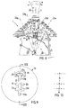
- Fig. 1 shows a diagrammatic end view, partially in cross-section, of a gear selector device according to the invention,
- Fig. 2 shows a diagrammatic side view, partially in cross-section, of the gear selector device in Fig. 1,
- Fig. 3 shows, from above, how the guide groove is designed in the embodiment according to Figs. 1 and 2,
- Fig. 4 indicates the different gear positions which can be obtained in Fig. 3,
- Fig. 5 shows a variant of the embodiment in Fig. 2,
- Figs. 6 and 7 are based on Fig. 5 and correspond to Figs. 3 and 4,
- Fig. 8 shows another variant of the embodiment in Fig. 2,
- Figs. 9 and 10 are based on Fig. 8 and correspond to Figs. 3 and 4,
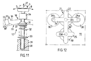
- Fig. 11 shows a detail of the manoeuvring column, and
- Fig. 12 shows a view, from below, of a section of the second locking part in the embodiment according to Figs. 1-3.
- A
gear selector device 1 according to the invention is designed to be connected in known manner via lines 2 to a control unit (not shown) which is intended for a motor vehicle gearbox and which, via the servo on the gearbox, effects engagement and disengagement of gears as a function of the position of amanoeuvring column 3 in thegear selector device 1, which column is manoeuvred by the driver. Since the invention relates solely to the gear selector device, only the latter is shown. - The control unit can be provided in a known manner, by means of different sensors, with information relating to the actual driving conditions and can, on the basis of this, calculate which gear should be used. The driver can in this way obtain information, for example via a gear indicator, on which gear is being used at a given time and on which gear the control unit recommends. This gives the driver the possibility of choosing, as and when required, the gear or gear-changing pattern. He can choose, for example, between automatic and manual transmission in different forms.
- The
manoeuvring column 3 is mounted in ahousing 4 which is intended to be fixed securely in the vehicle, and the column is mounted in a cradle 5 which is borne pivotably in thehousing 4. In this way, themanoeuvring column 3 together with the cradle 5 can be pivoted about a horizontal axis line 6 (Fig. 1), in the direction ofarrows 7 or 8 (Fig. 2). In the cradle 5, themanoeuvring column 3 is mounted pivotably about a horizontal axis line 9, in the direction ofarrows 10 or 11. The axis line 9 is at right angles to the axis line 6 and intersects the latter at apivoting centre 12 and is preferably oriented in the longitudinal direction of the vehicle. However, it is also possible for the axis lines 6 and 9 to be situated at different levels and, therefore, for the bearing of the manoeuvring column to be designed differently. - The
manoeuvring column 3 cooperates with a number ofdifferent sensors 13 for indicating different positions of the manoeuvring column. These sensors can be designed in a number of different ways and can consist for example, as shown, of circuit breakers which cooperate with suitably designedcam curves 14. For indicating the pivoting in the direction ofarrows cam curves 14 are secured in thehousing 4, or vice versa. For indicating the pivoting in the direction ofarrows 10 or 11, the cradle 5 can support one ormore sensors 15, for example circuit breakers, which cooperate withcam curves 16 on themanoeuvring column 3, or vice versa. It is also well known to use, for example, contactless sensors or other types of sensors. These sensors are connected via the lines 2 to the control unit (not shown). - Arranged between the free end of the manoeuvring column and the
pivoting centre 12 is alocking arrangement 17 by means of which themanoeuvring column 3 can be locked in predetermined positions, depending on which movement pattern has been chosen for the manoeuvring column. Thislocking arrangement 17 includes afirst locking part 18 arranged on themanoeuvring column 3, and asecond locking part 19 which is incorporated in the gearselector device housing 4 and is designed to cooperate with thefirst locking part 18. Thesecond locking part 19 can advantageously form a cover for thehousing 4 and is expediently protected by agaiter 20 which is attached to themanoeuvring column 3 and to thehousing 4. In thesecond locking part 19 there is aguide slot 21 intended for themanoeuvring column 3 and defining the movement pattern of the manoeuvring column. Thisguide slot 21 is normally made up of alonger slot 22, which permits manoeuvring in the direction ofarrows arrows 10 and 11. - In the embodiment according to Figs. 1-3, the
manoeuvring column 3 can be pivoted between four fixed positions in theslot 22, namely afirst position 22a at the level of theslot 23, asecond position 22b between theslots third position 22c at the level of theslot 24, and afourth position 22d at the level of theslot 25. In addition, it is possible to pivot themanoeuvring column 3 from thefourth position 22d in the direction ofarrow 8 to anon-locking position 22d' where the manoeuvring column remains only for as long as it is held there. - From the
position 22c at the level of theslot 24, the manoeuvring column can be pivoted either in the direction ofarrow 10 to a fixed position 24a, or in the direction of arrow 11 to afixed position 24b. From bothposition 22a atslot 23 andposition 22d atslot 25, themanoeuvring column 3 can be moved in the direction ofarrow 10 or 11 to non-locking side positions at the respective slot ends.
The meaning of the different positions of themanoeuvring column 3 in Figs. 1-3 emerges more clearly from Fig. 4, which shows diagrammatically the movement pattern according to Fig. 3. Position R corresponds toposition 22a and represents reverse position. By means of a sideways movement in theslot 23, a higher or lower reverse gear can be obtained, + and - indicating a change to a higher or lower gear, respectively, than that chosen by the automatic mechanism. The position N corresponds to position 22b and represents neutral position. The position AUTO corresponds to position 22c and represents automatic transmission. In position HOLD, corresponding to 24a, the engaged gear is held, while in position EBR, corresponding to 24b, the engine brake is coupled. In position REC, corresponding to 22d, the system recommends a specific gear, + and - indicating a change of recommended gear to a higher or lower gear, respectively, than that which is recommended. In the position SHIFT, corresponding to 22d', disengagement is carried out and the gear is changed on the basis of selection in the REC position. This embodiment according to Figs. 1-4 represents a fully automatic version in which the control device in the "automatic positions" chooses the gear and carries out gear-changing automatically. - Figs. 5-7 show instead a semiautomatic embodiment in which the control device selects the gear, but where the driver manoeuvres the clutch and thereby triggers the gear change. In the
guide slot 21 there is, as previously, alonger slot 22, but the number of transverse slots 23-26 is now four instead of three. There are five fixed positions in theslot 22, namely 22a-e. Only non-locking positions can be obtained in one direction in the transverse slots 23-26. - As emerges more clearly from Figs. 6 and 7, the
positions 22a-e correspond to R, N, 1, 2 and 3, respectively, where R and N represent, as previously, the reverse position and neutral position, respectively. Thepositions - Figs. 8-10 also show a semiautomatic embodiment, similar to that in Figs. 5-7. The transverse slots are here reduced to three, namely 23-25. There are still five fixed positions in the
slot 22, namely 22a-e. From theslot 22, only non-locking positions can be obtained in one direction in the slots 23-25. - According to Figs. 9 and 10, the
positions 22a-e here correspond to R, N, A, M and N, respectively, where R and N still represent the reverse position and neutral position, respectively. The positions A and M, corresponding to 22c and 22d, represent the automatic position and manual position, respectively. The position N corresponding to 22e represents an extra neutral position intended to be used in particular circumstances, for example in emergency situations, when decoupling of the whole gear selector device is desired. The symbols + and - have the same meanings as before. - The design of the locking
arrangement 17 emerges more clearly from Figs. 8, 11 and 12, where Fig. 11 shows in principle the same feature as in Fig. 8, but in simplified form. As has already been mentioned, the lockingarrangement 17 is divided up into afirst locking part 18 arranged on themanoeuvring column 3 and asecond locking part 19 cooperating with the first locking part and joined to thehousing 4. - In the
guide slot 21 there are arranged on the underside of the second locking part 19 a number of lockingmembers 30, here in the form of rounded recesses. These lockingmembers 30 can cooperate one at a time with afirst locking body 31 incorporated in the first lockingpart 18 and mounted displaceably on themanoeuvring column 3. With the aid of aspring 32, which bears against anattachment 33 arranged securely on themanoeuvring column 3, thefirst locking body 31 is loaded in the direction of the free end of the manoeuvring column. By means of cooperation withsuitable locking members 30, thefirst locking body 31 can in this way fix the manoeuvring column in the desired position. The rounded shape means that thefirst locking body 31 can be pivoted, counter to a certain force from thespring 32, between different fixed positions, i.e. can be brought into engagement with different locking members. At the same time, springing back to a centred position is possible by pivoting the manoeuvring column slightly past a centring locking member. From, for example, thecentred position 22d in Fig. 12, the manoeuvring column, when pivoted in either one direction inslot 25 or downwards inslot 22, can be made to spring back to thecentred position 22d. - The
manoeuvring column 3 also supports asecond locking body 34 incorporated in the first lockingpart 18 and situated so that the first and thesecond locking body second locking part 19. Thissecond locking body 34 is secured on themanoeuvring column 3 and is situated near or can slide along thesecond locking part 19 and its task is to cooperate with at least onelocking device 35 on thesecond locking part 19 so as to prevent themanoeuvring column 3 from being pivoted inadvertently to a particular setting. The lockingdevice 35 can consist, for example, of a raised section around thetransverse slot 23 for the reverse position R.A stop surface 36 on thelocking device 35 is intended to catch thesecond locking body 34. If required, however, thesecond locking body 34 can be made to pass the lockingdevice 35 in order to be able to engage reverse position, for example. This is possible by virtue of the fact that themanoeuvring column 3 is mounted axially movable and can be lifted in the direction ofarrow 37, counter to the force from thespring 32, at the same time as it is pivoted in the direction ofarrow 7. Upon pivoting back in the direction ofarrow 8, the manoeuvring column returns to its axially inner position under the effect of thespring 32. Thesecond locking body 34 can in this respect limit the return in the axial direction, but it is also possible, for example, to let the manoeuvring column touch the bottom of a moderatelydeep hole 38 in abracket 39 for the manoeuvring column. - Instead of arranging the locking
members 30, as shown here, on the inside of thesecond locking part 19 facing away from the free end of the manoeuvring column, the lockingmembers 30 can be arranged on the outside of thesecond locking part 19, with correspondingly different positioning of the first and thesecond locking bodies device 35. - The
recesses 30 and thefirst locking body 31 have been shown here with a rounded shape, but it is also possible to use other shapes which permit good locking in fixed positions and yet allow movement between fixed positions and permit springing-back in certain positions.
Claims (10)
- Gear selector device (1) for a gearbox intended for motor vehicles and of the type which is manoeuvred indirectly via a control unit connected to the gear selector device (1), provided with a pivotably mounted manoeuvring column (3), and with a locking arrangement (17) for locking the manoeuvring column (3) in predetermined positions, wherein the locking arrangement (17) includes a first locking part (18) arranged on the manoeuvring column (3), and a second locking part (19) which cooperates with the first locking part and is connected to a housing (4) in which the manoeuvring column is mounted, characterised in that said second locking part (19) has a guide slot (23) which is intended for the manoeuvring column (3) and in which there are locking members (30) which define the predetermined positions for the manoeuvring column (3) in the guide slot (23).
- Gear selector device according to Claim 1, characterised in that the second locking part (19) forms a cover for the housing (4) and is detachably mounted on the latter.
- Gear selector device according to Claim 1 or 2, characterised in that the locking members (30) consist of recesses which are arranged in the second locking part (19) and which cooperate with a first locking body (31), spring-loaded in the direction of the recesses, in the first locking part (18).
- Gear selector device according to Claim 3, characterised in that the first locking body (31) is displaceable along the manoeuvring column (3) and has a suitable form for centring in the recesses.
- Gear selector device according to Claim 3 or 4, characterised in that the recesses (30) are arranged in the side of the second locking part (19) facing away from the free end of the manoeuvring column (3).
- Gear selector device according to any of Claims 3-5, characterised in that the first locking part (18) also includes a second locking body (34) which, in relation to the first locking body (31), is arranged on the opposite side of the second locking part (19) and is designed, together with at least one locking device (35) on the latter, to prevent inadvertent pivoting of the manoeuvring column (3) to at least one predetermined position.
- Gear selector device according to Claim 6, characterised in that the locking device (35) consists of a raised portion at the said predetermined position, and in that the manoeuvring column (3) together with the second locking body (34) is axially displaceable to a level where the second locking body (34) can pass the locking device (35).
- Gear selector device according to any of Claims 1-7, characterised in that the guide slot (21) is formed of a first long slot (22) which is preferably designed to be oriented with its longitudinal direction in the longitudinal direction of the vehicle, and at least one second, shorter slot (23-26) which is directed transverse to the first slot (22).
- Gear selector device according to Claim 8, characterised in that in the guide slot (21) there are a number of fixed positions (22a-d, 24a, 24b) for the manoeuvring column (3), at least along the first slot (22).
- Gear selector device according to Claim 9, characterised in that, in at least one of the fixed positions (22d), the manoeuvring column (3) can be pivoted away to a non-locking position (22d') in at least one direction.
Applications Claiming Priority (3)
| Application Number | Priority Date | Filing Date | Title |
|---|---|---|---|
| SE8904372A SE465688B (en) | 1989-12-27 | 1989-12-27 | VAEXELVAELJARDON TO A VEHICLE VEHICLE LADA |
| SE8904372 | 1989-12-27 | ||
| PCT/SE1990/000856 WO1991010084A1 (en) | 1989-12-27 | 1990-12-20 | Gear selector device for a vehicle gearbox |
Publications (2)
| Publication Number | Publication Date |
|---|---|
| EP0460181A1 EP0460181A1 (en) | 1991-12-11 |
| EP0460181B1 true EP0460181B1 (en) | 1994-04-13 |
Family
ID=20377879
Family Applications (1)
| Application Number | Title | Priority Date | Filing Date |
|---|---|---|---|
| EP91901936A Expired - Lifetime EP0460181B1 (en) | 1989-12-27 | 1990-12-20 | Gear selector device for a vehicle gearbox |
Country Status (6)
| Country | Link |
|---|---|
| US (1) | US5195387A (en) |
| EP (1) | EP0460181B1 (en) |
| BR (1) | BR9007140A (en) |
| DE (1) | DE69008167T2 (en) |
| SE (1) | SE465688B (en) |
| WO (1) | WO1991010084A1 (en) |
Families Citing this family (17)
| Publication number | Priority date | Publication date | Assignee | Title |
|---|---|---|---|---|
| DE4332265C1 (en) * | 1993-09-23 | 1995-05-04 | Daimler Benz Ag | Arrangement for controlling the gear change of an automatically shifting gear change transmission of a motor vehicle |
| SE502155C2 (en) * | 1993-12-30 | 1995-09-04 | Saab Scania Ab | Device and method of a vehicle gearbox |
| US5722292A (en) * | 1994-06-02 | 1998-03-03 | Chrysler Corporation | Shift control mechanism to manually shift an automatic transmission |
| DE19503050A1 (en) * | 1995-02-01 | 1996-08-08 | Zahnradfabrik Friedrichshafen | Travel switch for powershift transmission |
| WO1997001455A1 (en) * | 1995-06-27 | 1997-01-16 | Scandmec Ab | Control device |
| US5767769A (en) * | 1995-07-28 | 1998-06-16 | Chrysler Corporation | Method of displaying a shift lever position for an electronically-controlled automatic transmission |
| US5680307A (en) * | 1995-06-28 | 1997-10-21 | Chrysler Corporation | Method of shifting in a manual mode of an electronically-controlled automatic transmission system |
| ES2162141T3 (en) * | 1996-03-08 | 2001-12-16 | Zf Lemfoerder Metallwaren Ag | SWITCHING DEVICE FOR A CHANGE OF MOTOR VEHICLES. |
| DE19609585A1 (en) * | 1996-03-12 | 1997-09-18 | Bayerische Motoren Werke Ag | Method to control continuous gearing, especially on motor vehicle |
| US5791197A (en) * | 1996-07-24 | 1998-08-11 | Grand Haven Stamped Products | Automatic transmission shifter with manual shift mode |
| DE19747333C1 (en) * | 1997-10-27 | 1999-04-22 | Ford Global Tech Inc | Selector lever arrangement for auxiliary gearboxes of motor vehicles |
| DE10022433B4 (en) * | 2000-05-09 | 2006-07-13 | Daimlerchrysler Ag | lever device |
| US6581485B1 (en) * | 2000-10-09 | 2003-06-24 | Deere & Company | Control lever knob rubber boot interface |
| FR2826915B1 (en) * | 2001-07-06 | 2003-09-26 | Valeo | DEVICE FOR CONTROLLING A GEARBOX FOR A MOTOR VEHICLE |
| US20080098849A1 (en) | 2006-10-31 | 2008-05-01 | Yong Qiang Wang | Modular automatic transmission shifter |
| DE102007018731B4 (en) * | 2007-04-20 | 2010-12-30 | Kongsberg Actuation Systems Gmbh | Switching and selection device |
| DE102014225131A1 (en) * | 2014-12-08 | 2015-12-31 | Schaeffler Technologies AG & Co. KG | Assembly with a manual shift lever of a motor vehicle transmission |
Family Cites Families (9)
| Publication number | Priority date | Publication date | Assignee | Title |
|---|---|---|---|---|
| US2917941A (en) * | 1958-03-13 | 1959-12-22 | Deere & Co | Selector means |
| FR1333227A (en) * | 1962-06-15 | 1963-07-26 | Renault | Gear shift control for gearbox and reducer transmission |
| JPS6012165Y2 (en) * | 1979-12-21 | 1985-04-20 | 日産自動車株式会社 | Automatic transmission operating device |
| US4338828A (en) * | 1980-05-21 | 1982-07-13 | Borg-Warner Corporation | Transmission shift control guide and detent apparatus |
| US4442730A (en) * | 1981-08-31 | 1984-04-17 | Twin Disc, Incorporated | Vehicle transmission system and a single lever control device therefor |
| US4646582A (en) * | 1983-06-27 | 1987-03-03 | Mitsubishi Jidosha Kogyo Kabushiki Kaisha | Operating device for transmission |
| DE3603609A1 (en) * | 1986-02-06 | 1987-08-20 | Ford Werke Ag | SHIFT SHAFT RETURN GUIDE FOR A MULTI-SPEED INTERCHANGEABLE GEARBOX, ESPECIALLY FOR MOTOR VEHICLES |
| DE3617256A1 (en) * | 1986-05-22 | 1987-11-26 | Audi Ag | DEVICE ON A MOTOR VEHICLE |
| US4912997A (en) * | 1989-06-02 | 1990-04-03 | Chrysler Corporation | Electric shift selector mechanism for transmission |
-
1989
- 1989-12-27 SE SE8904372A patent/SE465688B/en not_active IP Right Cessation
-
1990
- 1990-12-20 DE DE69008167T patent/DE69008167T2/en not_active Expired - Fee Related
- 1990-12-20 BR BR909007140A patent/BR9007140A/en not_active IP Right Cessation
- 1990-12-20 EP EP91901936A patent/EP0460181B1/en not_active Expired - Lifetime
- 1990-12-20 WO PCT/SE1990/000856 patent/WO1991010084A1/en not_active Ceased
- 1990-12-20 US US07/743,330 patent/US5195387A/en not_active Expired - Fee Related
Also Published As
| Publication number | Publication date |
|---|---|
| EP0460181A1 (en) | 1991-12-11 |
| SE465688B (en) | 1991-10-14 |
| BR9007140A (en) | 1991-11-26 |
| US5195387A (en) | 1993-03-23 |
| DE69008167D1 (en) | 1994-05-19 |
| SE8904372D0 (en) | 1989-12-27 |
| WO1991010084A1 (en) | 1991-07-11 |
| DE69008167T2 (en) | 1994-09-22 |
| SE8904372L (en) | 1991-06-28 |
Similar Documents
| Publication | Publication Date | Title |
|---|---|---|
| US5195387A (en) | Gear selector device for a vehicle gearbox | |
| CA1196804A (en) | Fluid actuated shift bar housing assembly | |
| US5509322A (en) | Shift control mechanism to manually shift an automatic transmission | |
| US4598374A (en) | Gearshift selection system for a power-assisted transmission | |
| US5197344A (en) | Shifting arrangement for an automatic transmission | |
| US4537088A (en) | Column shift type gear selector device for an automatic power transmission of an automotive vehicle | |
| US5038627A (en) | Vehicle transmission with manually shifted lower gears and automatically shifted upper gears | |
| KR101490893B1 (en) | Modular automatic transmission shifter | |
| US5682789A (en) | Selector lever system for manually shiftable automatic transmissions | |
| EP0936383B1 (en) | Shifting arrangement for automatic transmission of motor vehicle | |
| EP1013972B1 (en) | Apparatus for detecting gear positions of automobile transmission | |
| US5078020A (en) | Reverse select system for manual transmission | |
| GB2228980A (en) | Gearshift control with automatic control of clutch | |
| EP0349636B1 (en) | Park position shift selector mechanism and method | |
| US3646828A (en) | Transmission controls | |
| US4304144A (en) | Gear shift mechanism for automotive multi-speed transmission | |
| WO1990004225A1 (en) | Gear selector device for a vehicle gearbox | |
| GB2357323A (en) | A gear-shift mechanism which shifts to a low gear when a sensor fails | |
| US7469610B2 (en) | Reverse and park inhibitor apparatus in a transmission control mechanism | |
| US4344334A (en) | Change-speed transmission with speed-range selection means for motor vehicles, particularly for farm tractors | |
| KR102495149B1 (en) | Rotary type transmission for vehicle | |
| US4706514A (en) | Gear selector for manual transmission having reverse gear lockout | |
| EP0477603B1 (en) | Detent structure for an automatic transmission system | |
| US5806368A (en) | Gearshift device for a semiautomatically shiftable change-speed gearbox | |
| EP0247976B1 (en) | Motor vehicle gearbox |
Legal Events
| Date | Code | Title | Description |
|---|---|---|---|
| PUAI | Public reference made under article 153(3) epc to a published international application that has entered the european phase |
Free format text: ORIGINAL CODE: 0009012 |
|
| 17P | Request for examination filed |
Effective date: 19910802 |
|
| AK | Designated contracting states |
Kind code of ref document: A1 Designated state(s): DE FR GB IT |
|
| 17Q | First examination report despatched |
Effective date: 19930507 |
|
| GRAA | (expected) grant |
Free format text: ORIGINAL CODE: 0009210 |
|
| AK | Designated contracting states |
Kind code of ref document: B1 Designated state(s): DE FR GB IT |
|
| PG25 | Lapsed in a contracting state [announced via postgrant information from national office to epo] |
Ref country code: IT Free format text: LAPSE BECAUSE OF FAILURE TO SUBMIT A TRANSLATION OF THE DESCRIPTION OR TO PAY THE FEE WITHIN THE PRE;WARNING: LAPSES OF ITALIAN PATENTS WITH EFFECTIVE DATE BEFORE 2007 MAY HAVE OCCURRED AT ANY TIME BEFORE 2007. THE CORRECT EFFECTIVE DATE MAY BE DIFFERENT FROM THE ONE RECORDED.SCRIBED TIME-LIMIT Effective date: 19940413 Ref country code: FR Effective date: 19940413 |
|
| REF | Corresponds to: |
Ref document number: 69008167 Country of ref document: DE Date of ref document: 19940519 |
|
| EN | Fr: translation not filed | ||
| PLBE | No opposition filed within time limit |
Free format text: ORIGINAL CODE: 0009261 |
|
| STAA | Information on the status of an ep patent application or granted ep patent |
Free format text: STATUS: NO OPPOSITION FILED WITHIN TIME LIMIT |
|
| 26N | No opposition filed | ||
| REG | Reference to a national code |
Ref country code: GB Ref legal event code: 732E |
|
| PGFP | Annual fee paid to national office [announced via postgrant information from national office to epo] |
Ref country code: GB Payment date: 19971211 Year of fee payment: 8 |
|
| PG25 | Lapsed in a contracting state [announced via postgrant information from national office to epo] |
Ref country code: GB Free format text: LAPSE BECAUSE OF NON-PAYMENT OF DUE FEES Effective date: 19981220 |
|
| GBPC | Gb: european patent ceased through non-payment of renewal fee |
Effective date: 19981220 |
|
| PGFP | Annual fee paid to national office [announced via postgrant information from national office to epo] |
Ref country code: DE Payment date: 20020109 Year of fee payment: 12 |
|
| PG25 | Lapsed in a contracting state [announced via postgrant information from national office to epo] |
Ref country code: DE Free format text: LAPSE BECAUSE OF NON-PAYMENT OF DUE FEES Effective date: 20030701 |