EP0459667A1 - Sheet material feeder - Google Patents
Sheet material feeder Download PDFInfo
- Publication number
- EP0459667A1 EP0459667A1 EP91304436A EP91304436A EP0459667A1 EP 0459667 A1 EP0459667 A1 EP 0459667A1 EP 91304436 A EP91304436 A EP 91304436A EP 91304436 A EP91304436 A EP 91304436A EP 0459667 A1 EP0459667 A1 EP 0459667A1
- Authority
- EP
- European Patent Office
- Prior art keywords
- sheet
- lowermost
- stack
- feeding
- sheets
- Prior art date
- Legal status (The legal status is an assumption and is not a legal conclusion. Google has not performed a legal analysis and makes no representation as to the accuracy of the status listed.)
- Granted
Links
Images


Classifications
-
- B—PERFORMING OPERATIONS; TRANSPORTING
- B65—CONVEYING; PACKING; STORING; HANDLING THIN OR FILAMENTARY MATERIAL
- B65H—HANDLING THIN OR FILAMENTARY MATERIAL, e.g. SHEETS, WEBS, CABLES
- B65H3/00—Separating articles from piles
- B65H3/02—Separating articles from piles using friction forces between articles and separator
- B65H3/04—Endless-belt separators
- B65H3/042—Endless-belt separators separating from the bottom of the pile
-
- B—PERFORMING OPERATIONS; TRANSPORTING
- B65—CONVEYING; PACKING; STORING; HANDLING THIN OR FILAMENTARY MATERIAL
- B65H—HANDLING THIN OR FILAMENTARY MATERIAL, e.g. SHEETS, WEBS, CABLES
- B65H3/00—Separating articles from piles
- B65H3/46—Supplementary devices or measures to assist separation or prevent double feed
Landscapes
- Engineering & Computer Science (AREA)
- Mechanical Engineering (AREA)
- Sheets, Magazines, And Separation Thereof (AREA)
Abstract
Description
- This invention relates generally to sheetfeeders, and more specifically to feeders which feed one article at a time from the bottom of a stack of sheet articles.
- Sheet feeders which feed from the bottom of a stack often employ endless feed belts having a feeding surface contacting the bottom face of the lowermost sheet to thereby drive the sheet substantially in and along its plane from beneath the stack. Such sheet feeders commonly employ a restraining mechanism to prevent all but the lowermost sheet from being passed therethrough.
- Difficulties encountered with conventional feeders have included misfeeds in the form of double or multiple sheets being fed or, alternately, the absence of a sheet when it should have been fed. These difficulties are experienced particularly in high speed operation and when sheet articles of differing properties are handled. For instance, different material thickness, stiffness, surface friction, and different sheet sizes have critically affected reliable operation of such feeders. Sensitive mechanical adjustment has been generally required for particular sheet properties and sizes to assure reliable operation, and even relatively slight changes in such properties and/or sizes necessitated readjustment of the device. Consequently, such feeders have also been unable reliably to handle a mix of sheets.
- Prior art feeders for singulating and feeding individual sheets from the bottom of a stack have employed a variety of restrainer or retarder mechanisms to prevent all but the lowermost sheet to be fed. Such feeders are, for example, shown in the following U.S.Patents.
- Rouan (U.S.Patent No. 2,273,288) discloses an adjustable separator for stripping letters from the bottom of a stack. Adjustment facilitates substantially constant tension whilst the separator yields as letters of varying thickness pass therebeneath. Kramell et al (U.S. Patent No. 3,895,791) discloses a bottom sheet feeder comprising a separation belt and a retard pad that is biased against the belt to bow the belt down. Strobel (U.S. Patent No. 3,934,869) shows a sheet separating and feeding apparatus including a feed belt adapted for frictional engagement with retard means 38. Generally similar devices are also shown by Godlewski and by Larson in U.S.Patent Nos. 4,666,140 and 4,555,103, respectively.
- Imposition of transverse bowing onto sheet materials for various purposes during sheet handling and transporting is shown in prior art, for instance, by U.S.Patents No. 4,744,555 to Naramore et al, No. 4,663,527 to Koyama et al, and No. 2,157,228 to Buccicione et al.
- The present invention is defined in the claims.
- The sheet feeder of the present invention particularly obviates difficulties of the aforementioned kind and provides reliable singulating and feeding of sheet material from the bottom of a stack in high speed operation and for sheets that can vary significantly in properties as well as size. The instant sheet feeder tolerates substantial misalignments of individual sheets (including skew) without misfeeding and without the need for adjustments to accomodate different and mixed different sheet materials in uninterrupted operation. These characteristics provide significant operating and cost advantages not heretofore provided.
- An important feature of one aspect of the invention is the provision of an improved sheet feeder and an improved method of singulating and feeding sheets of different and mixed properties and sizes from the bottom of a stack disposed in a hopper. The feeder includes means for urging sheets in the stack toward a singulating exit region and means for feeding a lowermost sheet from the stack through a restrainer device, wherein the restrainer device restrains all but the lowermost sheet from feeding out from the hopper by virtue of transversely, resiliently corrugating the lowermost sheet while it passes through the restrainer device.
- In a first preferred embodiment, the restrainer device comprises a resilient member supported along a portion of an inner surface thereof on a support member and having an unsupported lateral overhang extending beyond the support member. Facing the outer surface of the resilient member in the region of the lateral overhang is an urging surface of a guide member. The spacing between the urging surface and the surface of the support member in a general direction normal to these surfaces is set to be the sum of the thickness of the resilient member between its inner and outer surfaces plus, at most, a distance that is less than the thickness of the thinnest sheet material operatively handled.
- In operation, a lowermost sheet is fed from the stack between the outer surface of the resilient member and the urging surface to resiliently deflect the lateral overhang portion of the resilient member in order to pass through. As a result, at least a portion of the lowermost sheet is transversely, resiliently corrugated or bowed while passing through the restrainer device. Effects of this corrugation, particularly lifting effects on sheets overlaying the lowermost sheet and especially in leading edge regions of these sheets, assist and enhance restraining effects of the restraining device to reliably avoid misfeeds of sheets, even if sheets of different and mixed properties and sizes are fed.
- In a second preferred embodiment, the restrainer device comprises two feed rollers. Each feed roller is disposed in juxtaposition to a guide member. The feed roller's outer periphery is spaced from the guide member by a gap that is preset to approximately correspond to (or to somewhat less than) the thickness of operatively-handled sheet material. The guide member's surface that is in juxtaposition to the feed roller's periphery is tangent to a plane that is disposed beneath and parallel to the sheet feeding plane, the sheet feeding plane being defined as the plane of the lowermost sheet in the hopper stack. The resilient member is laterally spaced in relation to the feed rollers and has its upper, outer surface disposed approximately in the sheet-feeding plane.
- In operation of this embodiment, a lowermost sheet is fed from the stack, being carried on the resilient member, and further through the gap between the feed roller and the guide member. As a result, at least a portion of the lowermost sheet is transversely, resiliently corrugated or bowed while passing through the restrainer device. Effects of this corrugation are as in the first embodiment.
- The sheet feeder of the invention is particularly useful in feeding of paper sheets, such as individual paper sheets (plain or folded), signatures, envelopes, brochures, booklets, and the like. The feeder is also advantageous in the feeding of cards and card booklets, and cardboard, and it can handle still more rigid sheet materials, for instance plastic and metal sheets, and the like.
- The foregoing and other objects, features and advantages of the invention will be apparent from the following more particular description of preferred embodiments of the invention, as illustrated in the accompanying drawings in which like reference numerals refer to like parts throughout different views. The drawings are schematic and not necessarily to scale, emphasis instead being placed upon illustrating principles of the invention:
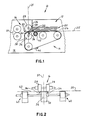
- FIG. 1 is a schematic side view of an embodiment of a sheet feeder according to principles of the present invention;
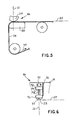
- FIG. 2 is a schematic frontal view of a portion of the embodiment shown in FIG. 1;
- FIG. 3 is a schematic sectioned enlargement of a fragmental portion of the view depicted in FIG. 2 showing further details;
- FIG. 4 is a schematic side view showing a portion of a feeder in another embodiment of the invention;
- FIG. 5 is a schematic side view showing a portion of a feeder in a further embodiment of the invention;
- FIG. 5A is a schematic side view showing a portion of a feeder in a yet further embodiment of the invention;
- FIG. 6 is a schematic side view showing detail aspects of a restrainer mounting according to the invention;
- FIGS. 7 and 8 are schematic front views illustrating portions of yet further embodiments of the invention;
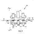
- FIG. 9 is a schematic frontal view illustrating a further embodiment of the invention; and,
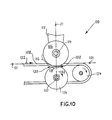
- FIG. 10 is a schematic side view of the embodiment illustrated in FIG. 9.
- Referring now to FIG. 1, there is depicted a
sheet feeder 10 comprising ahopper 12, abelt drive mechanism 14, arestraining mechanism 16, and a fragmentally-indicatedmounting structure 18. Additionally shown here is a driven pair of nip rollers 20 for further transporting of sheets delivered thereto fromfeeder 10. Further defined here is asingulating plane 21 which is oriented substantially perpendicularly with respect to the bottom plane ofhopper 12 and orthogonally to plane 25 of FIG. 1, which extends generally through the middle ofrestraining mechanism 16. - Hopper 12 holds a
sheet stack 22 including alowermost sheet 24.Sheet feeding plane 25 is indicated on the right side. Asingulating exit region 23 is designated as the general sheet exit region (at the left side of hopper 12) about in the middle of therestraining mechanism 16 in the region ofsingulating plane 21.Lowermost sheet 24 is substantially disposed insheet feeding plane 25. Disposed at the front end (left end) ofhopper 12 is abarrier wall 26 and, further frontwardly, therestraining mechanism 16 comprising a stationary guide member 28 (here shown in form of a cylindrical body).Guide member 28 includes anurging surface 30 represented by a downwardly and rightwardly facing portion of the guide member's periphery. The rightwardly facing portion is designated as afirst portion 32 and the downwardly facing portion is designated as asecond portion 34. -
Restraining mechanism 16 further comprises asupport member 36 and aresilient member 38 supported thereon.Support member 36 andresilient member 38 are shown here in the form of a revolving pulley and an endless belt, respectively -- both also comprised inbelt drive mechanism 14. -
Belt drive mechanism 14 further includes a plurality of pulleys carryingresilient member 38 in the form of an endless flat belt. At least one of the pulleys is motor-driven so thatresilient member 38 moves in the direction ofarrow 40. Also comprised inbelt drive mechanism 14 is anadjustable idler roller 42 that is borne freely revolvably upon an eccentrically mounted boss.Roller 42 can be adjusted to lift or lower the thereupon carried portion of the endless belt by angular adjustment of the eccentric boss. - As shown in FIGS. 2 and 3, at least one
guide member 28 is disposed laterally in a position so as to slightly overlapresilient member 38 in a region of a lateral overhang thereof oversupport member 36. FIG. 3 represents an enlarged portion of a section substantially throughsingulating plane 21. - Referring now more particularly to FIGS. 2 and 3,
support member 36 includes asupport surface 44 that has a supportingedge region 46 at least on one side thereof for supportingresilient member 38.Resilient member 38 has anouter surface 48 and aninner surface 50.Inner surface 50 contacts supportsurface 44 at least in a supportingedge region 46.Resilient member 38 overhangs laterally over the side ofsupport member 36 by alateral overhang 52.Second portion 34 of urging surface 30 (of guide member 28) has an urgingedge region 54 on one side thereof. In urgingedge region 54,second portion 34 of urgingsurface 30 facesouter surface 48, thusly forming anoverlap 56 over a portion of thelateral overhang 52 ofresilient member 38. - Also indicated in FIG. 3 is a portion of a
sheet 58 as it is being fed betweenguide member 28 andresilient member 38 through restrainingmechanism 16. - Particularly with reference to FIG. 2, a pair of
guide members 28 is shown, each guide member being disposed symmetrically on lateral sides ofresilient member 38 in mirror-image manner mirrored with respect to acenter plane 59. Additional belt drive means 60 supports sheets fed by the feeder. It should be noted that additional belt drive means 60 can be replaced by low-friction stationary guide surfaces for lateral support of fed sheets. Atypical sheet 62, fed betweenguide members 28 andresilient member 38, is indicated by a dotted line. It will be appreciated, also in view of FIG. 3, that sheets are slightly-transversely, resiliently corrugated, bowed, or waved slightly out of thesheet feeding plane 25 while being fed through restrainingmechanism 16, as indicated here bytypical sheet 62. - As illustrated in FIGS.1-3,
resilient member 38 can be a plain endless flat belt or a flat timing belt having teeth along its inner surface to engage corresponding grooves or teeth in the periphery of the belt-carrying pulleys. Conventional belts having appropriate resiliently elastic properties have been found adequate for purposes of this invention. Although it has been found that particular surface properties ofguide member 28 in its urgingsurface 30 have little, if any, influence on proper operation of the feeder, a preferred material forsurface 30 is polyurethane of 83 Shore A Durometer hardness. - In operation of a sheet material feeder as particularly depicted in FIGS. 1 and 2,
sheet stack 22 is urged towardsingulating plane 21 by the feeding motion of resilient member 38 (being a driven endless belt) upon which stack 22 is at least partially supported inhopper 22. Leading edges of all sheets but thelowermost sheet 24 impact onbarrier wall 26 or onguide member 28 and are stopped thereby. Thelowermost sheet 24 continues to be fed byresilient member 38 into thesingulating exit region 23 betweenguide member 28 andresilient member 38. Aslowermost sheet 24 is nipped therebetween, it is slightly-transversely, resiliently corrugated at least in the region ofsingulating exit region 23 by virtue of the structural relationships betweenmembers 28 and 38 (as particularly illustrated in FIG. 3). Hence, the next one or two or more sheets in the stack have their leading ends slightly lifted up. Moreover, the lowermost sheet is partially separated by the corrugation from the next sheet, which results in a significant reduction of friction therebetween. These effects reliably enhance the operation by avoidance of multiple sheet misfeeds. - The corrugated sheet is now delivered to further equipment, for instance via nip rollers 20. A thusly-delivered sheet can be sensed in order to temporarily stop
belt drive mechanism 14 until the delivered sheet has passed on some desired distance, when the belt drive mechanism is again energized to feed the next sheet. Spacing between successively delivered sheets can be thusly changed as desired. - The sheet corrugating operation can be best appreciated in view of FIG. 3. As a lowermost sheet is fed from the bottom of
sheet stack 22 uponresilient member 38, the leading edge of the sheet is forced underguide member 28 and the sheet slides therealong while it is fed. The spacing provided between supporting edge region 46 (of support member 36) and urging-edge region 54 (of guide member 28) is such that a sheet fed uponresilient member 38 resiliently deflectslateral overhang 52 while the sheet is slightly squeezed or nipped in the region ofoverlap 56 between urging-edge region 54 and the portion of the outer surface 48 (of resilient member 38) disposed in a deflected portion oflateral overhang 52. - In this respect, there is defined: a
first plane 63 that is substantially parallel tosheet feeding plane 25 and that is tangent to urgingsurface 30 in the region ofsingulating plane 21; and, asecond plane 65 that is parallel tofirst plane 63 and that is tangent to thesupport surface 44 at least in the supportingedge region 46 in the region ofsingulating plane 21. These first and second planes are preferably spaced apart by a distance that is less than the sum of the thickness of theresilient member 38 plus the smallest thickness of sheet material that is to be operatively moved through the singulator region. - For example, a gap of about one thousandth of an inch between the outer surface 48 (of a relaxed
resilient member 38 in absence of a sheet) facilitates reliable feeding and singulating of sheets with thicknesses in the approximate range of about .002 to .018 inches and thicker without readjustment. This gap can be further reduced to become an interference; for instance, an interference (negative gap) of .010 inches will still provide for reliable feeding of sheets in the aforementioned thicknesses. Such an interference has been found advantageous, but not essential, when sheet material of particularly unusual or troublesome surface characteristics is used. - In respect to larger sheet material thicknesses, for instance those considerably in excess of .018 inches, it has been found that a gap of .010 inches reliably handles most customary sheet materials. A preferred length for
overhang 52 to handle most customary sheet materials is in the range of about 1/8 of an inch or more, and not substantially less than about 1/16 of an inch. It will be appreciated that overlap 56 is always less thanoverhang 52. A preferred length forlateral overlap 56, also to handle most customary sheet materials, is about 1/16 of an inch or more. Moreover, reliable handling of sheet materials in thicknesses approaching 1/4 of an inch, for instance as given by coupon books and the like, is facilitated by the sheet material feeder according to the principles of the invention by appropriate gap adjustment and by provision of a correspondingly longerlateral overhang 52. -
Hopper 12, shown in FIG. 1, need not be oriented horizontally but can be tilted downwardly toward singulating plane 21 (from right to left). It has been found that a tilt of up to about 30 degrees does not significantly affect operation. Moreover, operation at a greater tilt is feasible by appropriate adjustments of structural component relationships. - In respect to the shape of urging
surface 30 in transverse direction, it should be noted that other than planar shapes can be employed, such as for instance convex, concave, stepped or undercut, grooved, and the like. Similarly,support surface 44 can be in a variety of shapes. In this respect, for instance whensupport member 36 is a pulley, it can have a cylindrical shape, a crowned, barrel shape, and the like. - In regard to the relative locations of
guide member 28 andsupport member 36, whereas FIG. 1 illustrates these two components one above the other generally disposed insingulating plane 21, guide member 28 (together with barrier wall 26) can be located some small distance upstream so that it is no longer disposed directly above the center line ofsupport member 36. - Referring now to FIG. 4, another embodiment of the invention is illustrated here by the portion that differs from the embodiment depicted in FIGS.1 and 2. In particular, a restraining
mechanism 66 is provided comprising guide member 28 (the same or similar as shown in FIGS.1-3) and aresilient member 68 in form of a sleeve borne about the periphery of asupport member 76, whereinsupport member 76 is a driven roller.Support member 76 is substantially similar to supportmember 36 of FIGS.1-3. The portion of abelt drive mechanism 78 disposed in the vicinity ofsupport member 76 is shown here to include a revolvingpulley 80 and an endlessflat belt 82 that is driven in the direction ofarrow 83. When viewed in conjunction with FIG. 1, it will be apparent thatbelt drive mechanism 78 differs only insignificantly from belt drive mechanism 14 (FIG. 1). - In particular,
belt drive mechanism 78 now extends leftwardly for a shorter distance and does not include a portion of restraining mechanism 66 (16 in FIG. 1). Sheets are fed (substantially in sheet feeding plane 25) from the hopper upon the top of endlessflat belt 82 to and through the nip betweenresilient member 68 and guidemember 28.Support member 76 is driven to provide the same outer surface speed forbelt 82 andresilient member 68. - With respect to further details of structure and operation, the embodiment indicated in FIG. 4 is similar or identical to the embodiment illustrated in and described in conjunction with FIGS. 1-3. Particularly also FIG. 3 and the description presented therewith is equally applicable.
- Referring now to FIG. 5, a further embodiment of the invention is illustrated here by the portion that differs from the embodiment depicted in FIGS. 1 and 2. In particular, a restraining
mechanism 86 is provided comprising guide member 28 (the same or similar as shown in FIGS. 1-3) andresilient member 38 substantially the same as in FIGS. 1-3. The only significantly different component being asupport member 88 in form of a stationary slide block adapted to facilitate sliding thereover ofresilient member 38 in the driven direction indicated byarrow 40. The slide block ofsupport member 88 is made preferably of a low friction material, such as for instance given by Delrin, Teflon, and the like, but can be made of other materials too.Support member 88 in sectional view of its upper portion (together withguide member 28 and resilient member 38) is substantially identical to supportmember 36 in the depiction in FIG. 3, and the description presented in conjunction therewith is equally applicable. - Referring now to FIG. 5A, a further embodiment is illustrated in regard to aspects differing from those shown in FIG. 5. A restraining
mechanism 89 is provided comprisingguide member 28,support member 89A, and resilient member 89C (in the form of an endless belt). Resilient member 89C is carried bypulley 89B (and at least one other pulley not shown here) and is driven in the direction ofarrow 40.Support member 89A is provided in the form of a stationary slide block adapted to facilitate sliding thereover of resilient member 89C. In all other respects and in function, restrainingmechanism 89 is similar or identical to the mechanism shown in FIG. 5, and the description given in conjunction therewith is equally applicable. - With respect to further details of structure and operation, the embodiments indicated in FIGS. 5 and 5A are similar or identical to the embodiment illustrated in and described in conjunction with FIGS. 1-3.
- Referring now to FIG. 6, a mounting
arrangement 90 for mountingguide member 28 to mountingstructure 18 of a sheet feeder according to the invention includes abracket 92, means for adjusting the vertical position ofguide member 28, and means for spring-loading guide member 28 downwardly. As indicated, the arrangement is disposed generally insingulating plane 21 having the lowermost portion ofguide member 28 disposed in the general proximity ofsheet feeding plane 25.Bracket 92 is rigidly mounted to structure 18 (and can be also or alternately attached to barrier wall 26) by conventional means not shown. - A boss 94 having an
adjustment knob 95 extends vertically adjustably (for instance screw-threadedly) through a hole inbracket 92. Ablock 96 is borne on boss 94 vertically slideably and is irrotationally guided. Astop collar 97 is affixed to the lower end of boss 94. A compression spring 98 is threaded over boss 94 and extends betweenbracket 92 andblock 96 in preloaded manner so thatblock 96 is forced downwardly againststop collar 97.Guide member 28 is attached to block 96. The vertical position ofblock 96 and therewith ofguide member 28 can be adjusted, for instance, by turning ofknob 95. - It will be apparent that
guide member 28 can move upwardly from an adjusted position against the spring-loading of spring 98. This latter effect is utilized, for example, when a thick sheet material article is fed beneathguide member 28 such that the resilient elastic properties ofresilient member 38 in the arrangements of the restraining mechanism for instance (as shown in FIGS. 1-5) are inadequate to provide commensurate resilient give. It has been found, however, that spring-loading by spring 98 is not required for proper normal operation of the feeder when the properties of fed sheet materials (for instance thicknesses) do not grossly vary during a particular run. Therefore, in such an embodiment, spring 98 is omitted and guidemember 28 is adjusted by adjustment means (knob 95, boss94) to a substantially fixed position to suit a relatively wide range of particular sheet thicknesses handled. - In respect to the particular mounting arrangement and adjusting means (for guide member 28) shown here by example, it should be understood that other suitable conventional devices can be employed to function equally well. For instance,
guide member 28 can be mounted in an angularly-adjustable cantilever mechanism. - Referring now to FIGS. 7 and 8, two further examples of slightly differing embodiments to the ones discussed hereinbefore are illustrated. The differences will be appreciated particularly also in view of the depiction in FIG. 2.
- FIG. 7 includes two support members 36 (each carrying a resilient member 38) and each of the two
guide members 28 overlap the respective resilient member at a laterally-opposite side. The arrangement is substantially symmetrical again aboutcenter plane 59. In other respects this arrangement is substantially identical to the embodiment depicted in FIG. 2. Particularly also FIG. 3 and the description given in conjunction therewith is similarly applicable to the embodiment of FIG. 7. - FIG. 8 also includes two support members 36 (each carrying a resilient member 38) and each of the two
guide members 28 overlap the respective resilient member at a laterally opposite side (albeit different sides to the ones of FIG. 7). The arrangement is substantially symmetrical again aboutcenter plane 59. In other respects this arrangement is also substantially identical to the embodiment depicted in FIG. 2. Particularly also FIG. 3 and the description given in conjunction therewith is similarly also applicable to the embodiment of FIG. 8. - Although the depictions of FIGS. 7 and 8 show symmetrical arrangements (with respect to center line 59) of preferred embodiments, it should be understood that the arrangements' symmetry is adopted here for the sake of convenience, rather than to imply a structural limitation. It will be appreciated that an appropriate asymmetrical layout of the components can function equally well.
- As the foregoing descriptions in conjunction with FIGS. 1-6 are applicable also to the depictions of FIGS. 7-8, no further discussion is offered here with respect to the latter.
- A further embodiment of the invention is illustrated in FIGS. 9 and 10 and includes a
restrainer mechanism 100 that is here employed instead of the restrainingmechanism 16 of FIG. 1. For clarification purposes, thesingulating plane 21 of FIG. 1 is also indicated in FIG. 10 to assist in locating therestrainer mechanism 100 in relation to the illustration of thefeeder 10 in FIG. 1. The region at and vicinal to thesingulating plane 21 is designated asexit region 102 in FIG. 10. - A sheet-feeding
plane 101 is defined as the plane in which the lowermost sheet is disposed at the bottom of the sheet stack (lowermost sheet 24, sheet stack 22 - FIG. 1) and in which the lowermost sheet is generally fed to and throughexit region 102.Sheet feeding plane 101 is shown in dot-dash representation in FIGS. 9 and 10. -
Restrainer mechanism 100 comprisesfeed rollers 104, guidemembers 106, andresilient members Feed rollers 104 are borne on acommon shaft 110 and are driven thereby in direction ofarrow 112 by means not shown.Feed rollers 104 can be provided with an elastically-resilient periphery, for instance by having at least an annular cylindrical peripheral portion of polyurethane material or of a similar elastomer. -
Guide members 106 are shown in form of cylindrical bodies. Although the guide members could be revolvable, they are stationary for purposes of a preferred mode of operation. Hence as shown here, guidemembers 106 are mounted upon acommon shaft 114 which is attached to amounting block 117 that, in turn, is mounted in the framework of the feeder (not shown here).Guide members 106 include along their peripheries a first surface portion 116 (FIG. 10) which approximately faces leading edges of particularly the lower sheets of the stack in the hopper (located to the left in FIG. 10). -
Guide members 106 also include a second-surface portions 118 substantially disposed in the region of juxtaposition with respect to feedrollers 104. Second-surface portion 118 can be provided with elastically resilient properties, for instance by employment of polyurethane material or a similar elastomer for this portion of the guide members. In general, for practical reasons, the entire periphery of theguide members 106 can be advantageously made of elastomeric material. Elastically resilient characteristics ofguide members 106 are advantageous, but not essential, to proper operation of the restraining mechanism, unless extreme ranges of mixed sheet material thicknesses and/or of other properties are to be handled. -
Guide members 106 are disposed with respect tosheet feeding plane 101 such that second-surface portions 118 are substantially tangent to a plane that is disposed substantially beneath and parallel with respect to thesheet feeding plane 101. Hence also the upper peripheries of feed rollers 104 (that are juxtaposed to second-surface portions 118) are disposed substantially beneath and parallel with respect to thesheet feeding plane 101. As indicated hereinbefore, guidemembers 106 are stationary in a preferred mode of operation. Consequently, the shape of their peripheral surfaces need not be cylindrical except that their first andsecond surface portions - A roller/
guide gap 120 is defined as the spacing between thesecond surface portion 118 and the upper periphery offeed roller 104. Thisgap 120 is set to a spacing that is equal to or less than the range of sheet material thicknesses that is to be operatively handled by the feeder device in a particular run or batch. -
Resilient members resilient member 108 is necessary for proper operation according to the invention.Resilient members 108′ are provided as helper belts to assist in handling of laterally-wider sheet material; to provide for additional transverse corrugations (bends) in the sheet material; and, to reduce excessive bowing of lateral sides of sheets (out of the sheet feeding plane). Any one or all ofresilient members arrow 122. The belts can also be free-running. In the situation of driven belts, the belts are operative as feeder belts and, therefore, are driven substantially at the same speed as the peripheries of thefeed rollers 104. As indicated, resilient members 108 (and 108′) can be supported bypulleys 124 and additional suitable pulleys not shown here. It should be noted that, for clarity's sake,resilient member 108 is shown sectioned in FIG. 9 (to show pulley 124). Pulleys bearingresilient members 108′ are not shown here. - At least a portion of the upper surfaces of
resilient members sheet 128 as it is being fed through therestrainer mechanism 100. - FIG. 9 illustrates also preferred lateral relationships between key features of this embodiment.
Resilient member 108 is disposed approximately along the middle region of sheet material (in direction of feed thereof).Guide members 106 andfeed rollers 104 are approximately symmetrically, laterally spaced from and disposed on either side ofresilient member 108.Resilient members 108′ (helper belts) are further approximately symmetrically laterally spaced from respectivelyadjacent guide members 106 andfeed rollers 104. - As a result of the lateral spacings together with the vertical relationships of
resilient members sheet 128 is transversely corrugated or bowed while it is being fed throughexit region 102, as indicated in FIG. 9. It will be apparent from this illustration that different transversely spaced portions ofsheet 128 are engaged and are fed along guide members 106 (and by feed rollers 104) and upon and alongresilient members - In operation of the embodiment of the invention described in conjunction with FIGS.9 and 10 (and partly referring back to portions of the illustration in FIG. 1), a stack of hopper-held sheets is urged in direction of
arrow 122 toward the singulating plane 21 (also see FIG. 1) and therewith also towardexit region 102 either by urging means (not shown) or by means of the endless belts of restrainingmembers first surface portion 116 ofguide members 106 and are stopped thereby from moving further. The lowermost sheet continues to be fed to and throughexit region 102 alongsecond surface portion 118 and therebetween and feedrollers 104 through roller/guide gap 120. - As indicated in FIG. 9,
lowermost sheet 128 is engaged at different transverse positions bysecond surface portions 118 ofguide members 106 and by upper surfaces ofresilient members second surface portions 118 are disposed in a plane that is parallel to and beneath thesheet feeding plane 101, whereas upper surfaces ofresilient members sheet feeding plane 101. Thelowermost sheet 128 is thereby transversely elastically corrugated or bowed in a transverse wave-like manner as illustrated in FIG. 9. This corrugating or bowing occurs in theexit region 102 and extends at least some distance upstream. Hence, the next one or two or more sheets in the stack have their leading ends slightly lifted up. This effect enhances separation of the lowermost sheet from the next sheet and supports stoppage of the next sheet at its leading edge by thefirst surface portion 116, as long as at least a portion of the lowermost sheet (being corrugated) supports this next sheet. Moreover, because the lowermost sheet is partially separated by its corrugation from the next sheet, significant reduction of friction effects result thereby between the lowermost sheet and the next sheet. Hence, the lowermost sheet can easier slide from beneath the next sheet without dragging the next sheet along. These effects enhance reliable operation and avoid multiple sheet misfeeds. - The
lowermost sheet 128 is then delivered to further equipment, for instance by and uponresilient members 108 and/or 108′ or by other conventional conveying means, not shown. - While the invention has been particularly shown and described with reference to preferred embodiments thereof, it will be understood by those skilled in the art that various changes and modifications in form and details may be made therein without departing from the spirit and scope of the invention.
Claims (12)
- A sheet material feeder (10) for seriatim feeding of lowermost sheets (24, 128) from a sheet stack, said sheet material feeder comprising:
a sheet hopper (12) for holding a stack of sheets (22), said sheet hopper (12) having a singulating exit region (23, 102) and feeding means (14) for urging a lowermost sheet (24, 128) toward said singulating exit region (23, 102);
a sheet feeding plane (25, 101) in which said lowermost sheet (24, 128) of said sheet stack (22) is substantially disposed while being fed from said sheet stack (22);
restraining means (16, 100) for restraining all but the lowermost sheet (24, 128) of said sheet stack (22) from feeding through said exit region (23, 102), said restraining means including:
first and second surface means (32, 116 AND 34, 118), said second surface means facing at least a portion of said feeding means (14) in said exit region (23, 102) and forming a gap therebetween and said first surface means (32, 116) facing toward the leading edges of sheets (22) of said stack of sheets;
support means (36, 124);
at least one resilient member (38, 108) supported by said support means (36, 124);
said feeding means (14) being operative to feed said lowermost sheet through said gap; and,
said resilient means (38, 108) and said second surface being mutually cooperative to bend said lowermost sheet (24, 128) relative to said sheet feeding plane as said lowermost sheet (24, 128) passes through said gap to thereby corrugate said lowermost sheet as it passes through said exit region (23, 102). - The apparatus of claim 1 wherein said resilient member is wider than said support member to thereby have a lateral overhang portion thereof extending beyond the width of said support member.
- The apparatus of claim 2 wherein said second surface means is located adjacent said lateral overhang portion and spaced therefrom so that passage of said lowermost sheet through said gap causes said lowermost sheet and said lateral overhang to bend and result in said corrugation of said lowermost sheet.
- A sheet material feeder (10) for seriatim feeding of lowermost sheets (24) from a sheet stack (22), said sheet material feeder comprising:
a sheet hopper (12) for holding a stack of sheets (22), said sheet hopper (12) having a singulating exit region (23) and means (14) for urging sheets (24) toward said singulating exit region (23);
a sheet feeding plane (25) in which said lowermost sheet (24) of the sheet stack (22) is substantially disposed while being fed from the sheet stack (22);
a singulating plane (21) through said singulating exit region (23) and oriented substantially orthogonally to the direction in which said lowermost sheet (24) is fed from the sheet stack (22);
means for feeding said lowermost sheets (24) from said sheet hopper (12) through said singulating plane (21);
first and second restraining means (16) for restraining all but the lowermost sheet (24) of the sheet stack (22) from feeding through said singulating plane (21);
said first restraining means including a guide member (28), said guide member (28) including an urging surface (30) having an urging edge region on one side thereof;
said urging surface (30) including a first (32) and a second (34) portion, said first portion (32) generally facing toward leading edges of lower sheets (24) in the sheet stack (22);
said second restraining means (34) including a support member (36) and a resilient member (38) supported thereon, said support member (36) including a support surface (44) having a supporting edge region (46) on one side thereof and supporting said resilient member (38);
said resilient member (38) having an outer (48) and an inner (50) surface and a thickness therebetween, said inner surface (50) including a contact-surface region substantially contacting said support surface (44);
said resilient member (38) including a lateral overhang (56) extending laterally beyond said supporting edge region (46), wherein said second portion (34) of said urging surface faces said outer surface (48) in the region of said lateral overhang (56);
a first plane (63) substantially parallel to said sheet feeding plane (25); and,
a second plane (65) parallel to said first plane (63);
wherein said first and second planes (63, 65) are spaced apart by a distance that is less than the sum of said thickness of said resilient member plus the smallest thickness of sheet material (24) operatively handled by said sheet material feeder (10), and wherein said lowermost sheets (24) are fed through said singulating plane between said urging edge region (54) and said outer surface (48). - A sheet material feeder (10) for seriatim feeding of lowermost sheets (128) from a sheet stack (22), said sheet material feeder comprising:
a sheet hopper (12) for holding a stack of sheets (22), said sheet hopper having an exit region (102) and means (14) for urging sheets toward said exit region, the position and orientation of the lowermost sheet (128) in said stack of sheets defining a sheet feeding plane (101);
means for feeding the lowermost sheet (128) of said stack of sheets (22) to said exit region (102) substantially along said sheet-feeding plane (101); and,
restraining means (100) for restraining all but the lowermost sheet (128) of said stack of sheets (22) from being fed through said exit region (102), said restraining means (100) being disposed substantially in said exit region (102) and including:
at least two feed rollers (104 - FIG. 10) for feeding the lowermost sheet (128) through said exit region (102), said feed rollers (104) being transversely spaced with respect to one another,
at least two guide members (106) each including a first (116) and a second (118) surface portion, said first surface portion (116) generally facing toward leading edges of lower sheets of said stack of sheets (22) and said second surface portion (118) including a periphery that is spaced from said sheet feeding plane (101), said periphery facing toward the periphery of one of said at least two feed rollers (106) and spaced therefrom to define a gap (120), said feed rollers being operative in feeding thereupon the lowermost sheet (128) adjacent said second surface portions (118);
at least one resilient member (108) laterally spaced from said guide members (106) for carrying the lowermost sheet (128) through said exit region (102);
whereby the lowermost sheet is transversely resiliently corrugated between transverse portions thereof with respect to said sheet feeding plane between said at least one resilient member and said at least two feed rollers and guide members while the lowermost sheet is being fed through said exit region. - The apparatus of any one of claims 1 through 5 wherein said first and second surface means are stationary.
- The apparatus of any one of claims 1-6 wherein said resilient member is an endless belt.
- A method of seriatim feeding of lowermost sheets from a stack of sheets in a sheet feeder of the type in which a support member has a resilient member mounted thereon so that an overhang portion of said resilient member overhangs the width of said support member and an urging means is located adjacent said overhang portion to form a gap therebetween that is offset from a sheet feeding plane at least when a sheet is moved between said urging means and said overhang portion, said method comprising the steps of:
locating the lowermost sheet of said stack in a sheet-feeding plane which extends through a singulating exit region and restraining all but the lowermost sheet of said sheet stack from feeding through said singulating exit region;
feeding said lowermost sheet from said hopper in said sheet feeding plane to move said lowermost sheet toward said singulating exit region and through said gap between said urging means and said overhang portion;
Corrugating said lower sheet as a transverse portion of said sheet is fed through such offset gap and partly out of said sheet feeding plane while being moved through said singulating exit region. - A method of seriatim feeding of lowermost sheets from a sheet stack (22) disposed in a hopper (12) having an exit region (102), the position and orientation of the lowermost sheet (128) in said sheet stack (22) defining a sheet feeding plane (101), the method comprising the steps of:
urging said sheets (128) toward said exit region (102);
feeding the lowermost sheet (128) to said exit region (102);
restraining all but the lowermost sheet from being fed through said exit region, said step of restraining including:
feeding the lowermost sheet along first and second transverse portions thereof through said exit region substantially parallel to said sheet feeding plane (101) between at least two feed rollers (104) and at least two guide members (106), respectively;
carrying further transverse portions of the lowermost sheet (128) through said exit region (102) substantially in said sheet feeding plane (101) upon at least one resilient member (108) that is laterally spaced from said guide members (106); and,
resiliently corrugating at least a portion of the lowermost sheet (128) transversely to the direction of lowermost sheet feeding at least in said exit region (102). - Apparatus for feeding sheet material from a sheet material stack (22), the apparatus comprising receiving means (12) for receiving the stack, urging means (14) for advancing the lowermost sheet from the stack, and bending means (28, 36, 38) for cooperating with the lowermost sheet to form a corrugation or wave or bow in the sheet as it is drawn from the stack, in order to facilitate separation of the lowermost sheet from the next sheet in the stack.
- Apparatus according to claim 10, wherein the bending means comprises a pair of guides (28) to engage one side of the sheet (24), the guides of the pair being spaced apart in a direction transverse to the direction of advance of the sheet, and a co-operating member or members (36, 38) to engage the other side of the sheet in the zone between the guides.
- A method for feeding sheet material from a sheet material stack, the method comprising advancing the lowermost sheet of the stack, and bending the lowermost sheet as it is drawn from the stack to form a corrugation or wave or bow in the sheet, in order to facilitate separation of the lowermost sheet from the next sheet in the stack.
Applications Claiming Priority (4)
| Application Number | Priority Date | Filing Date | Title |
|---|---|---|---|
| US52456390A | 1990-05-17 | 1990-05-17 | |
| US524563 | 1990-05-17 | ||
| US65927091A | 1991-02-22 | 1991-02-22 | |
| US659270 | 1991-02-22 |
Publications (2)
| Publication Number | Publication Date |
|---|---|
| EP0459667A1 true EP0459667A1 (en) | 1991-12-04 |
| EP0459667B1 EP0459667B1 (en) | 1994-11-17 |
Family
ID=27061533
Family Applications (1)
| Application Number | Title | Priority Date | Filing Date |
|---|---|---|---|
| EP19910304436 Expired - Lifetime EP0459667B1 (en) | 1990-05-17 | 1991-05-17 | Sheet material feeder |
Country Status (3)
| Country | Link |
|---|---|
| EP (1) | EP0459667B1 (en) |
| JP (1) | JP2664555B2 (en) |
| DE (1) | DE69105165T2 (en) |
Cited By (3)
| Publication number | Priority date | Publication date | Assignee | Title |
|---|---|---|---|---|
| EP1108665A2 (en) * | 1995-03-18 | 2001-06-20 | Watkiss Automation Limited | Suction device for feeding sheet material |
| US6705605B2 (en) | 2000-04-29 | 2004-03-16 | Watkiss Automation Limited | Methods of and apparatus for feeding sheets of material |
| RU2553651C1 (en) * | 2011-11-10 | 2015-06-20 | Оки Электрик Индастри Ко., Лтд. | Carrier separation and supply mechanism |
Citations (4)
| Publication number | Priority date | Publication date | Assignee | Title |
|---|---|---|---|---|
| NL6900533A (en) * | 1969-01-13 | 1970-07-15 | ||
| DE3018513A1 (en) * | 1979-05-14 | 1980-11-27 | Ricoh Kk | SHEET FEEDER |
| CA1127193A (en) * | 1979-10-03 | 1982-07-06 | John A. Long | Sheet feeder |
| DE3508981A1 (en) * | 1985-01-28 | 1986-08-07 | Glory Kogyo K.K., Himeji, Hyogo | DEVICE FOR DISPENSING PAPER SHEETS |
-
1991
- 1991-05-15 JP JP13863591A patent/JP2664555B2/en not_active Expired - Lifetime
- 1991-05-17 EP EP19910304436 patent/EP0459667B1/en not_active Expired - Lifetime
- 1991-05-17 DE DE1991605165 patent/DE69105165T2/en not_active Expired - Fee Related
Patent Citations (4)
| Publication number | Priority date | Publication date | Assignee | Title |
|---|---|---|---|---|
| NL6900533A (en) * | 1969-01-13 | 1970-07-15 | ||
| DE3018513A1 (en) * | 1979-05-14 | 1980-11-27 | Ricoh Kk | SHEET FEEDER |
| CA1127193A (en) * | 1979-10-03 | 1982-07-06 | John A. Long | Sheet feeder |
| DE3508981A1 (en) * | 1985-01-28 | 1986-08-07 | Glory Kogyo K.K., Himeji, Hyogo | DEVICE FOR DISPENSING PAPER SHEETS |
Non-Patent Citations (2)
| Title |
|---|
| PATENT ABSTRACTS OF JAPAN vol. 9, no. 149 (M-390)(1872) June 25, 1985 & JP-A-60 26 538 (CANON ) February 9, 1985 * |
| XEROX DISCLOSURE JOURNAL vol. 4, no. 1, February 1979, page 63; V.R.GREEN: 'sheet feeding method for machines with belt transport ' * |
Cited By (4)
| Publication number | Priority date | Publication date | Assignee | Title |
|---|---|---|---|---|
| EP1108665A2 (en) * | 1995-03-18 | 2001-06-20 | Watkiss Automation Limited | Suction device for feeding sheet material |
| EP1108665A3 (en) * | 1995-03-18 | 2002-01-23 | Watkiss Automation Limited | Suction device for feeding sheet material |
| US6705605B2 (en) | 2000-04-29 | 2004-03-16 | Watkiss Automation Limited | Methods of and apparatus for feeding sheets of material |
| RU2553651C1 (en) * | 2011-11-10 | 2015-06-20 | Оки Электрик Индастри Ко., Лтд. | Carrier separation and supply mechanism |
Also Published As
| Publication number | Publication date |
|---|---|
| DE69105165T2 (en) | 1995-04-13 |
| JP2664555B2 (en) | 1997-10-15 |
| JPH04226224A (en) | 1992-08-14 |
| DE69105165D1 (en) | 1994-12-22 |
| EP0459667B1 (en) | 1994-11-17 |
Similar Documents
| Publication | Publication Date | Title |
|---|---|---|
| JPS602115Y2 (en) | sheet processing equipment | |
| EP0528493B1 (en) | Roller-accumulator for sheets | |
| US4607832A (en) | Endless belt separator having an unsupported separating surface | |
| US5033729A (en) | Mechanism for the handling and singulating of flat materials | |
| US4114870A (en) | Document handling and counting device having guide fingers for facilitating the feeding of curled, folded and creased documents and further having improved outfeed stacker means for facilitating the neat stacking of documents of the aforementioned type | |
| JP3406395B2 (en) | Paper feeder | |
| EP0565633B1 (en) | Paper sheet feeding apparatus | |
| US3831928A (en) | Single sheet document feeder | |
| US5370379A (en) | Sheet registration and feeding apparatus | |
| US3485489A (en) | Document feeding mechanism | |
| US5318285A (en) | Roller/guide plate assembly for ninety degree document transfer unit | |
| US5110107A (en) | Sheet material feeder | |
| US3738642A (en) | Separator for new paper money | |
| EP0459667A1 (en) | Sheet material feeder | |
| US4374586A (en) | Document feed sheet aligner | |
| US5441249A (en) | Method and device for separating lifts from a stack of sheets | |
| US5564684A (en) | Anti-shingling buckle chute folder system | |
| US6305684B1 (en) | Feed rollers with reversing clutch | |
| CA2041962A1 (en) | Sheet material feeder | |
| US3949981A (en) | Mechanism for stacking sheets | |
| WO1982000994A1 (en) | Separator mechanism for envelope or sheet feeding apparatus | |
| EP0043262B1 (en) | Apparatus for bottom feeding articles from a stack | |
| JPH04358637A (en) | Paper feeding device of image forming unit | |
| JPH1072144A (en) | Printer | |
| JPH09136735A (en) | Sheet delivery device |
Legal Events
| Date | Code | Title | Description |
|---|---|---|---|
| PUAI | Public reference made under article 153(3) epc to a published international application that has entered the european phase |
Free format text: ORIGINAL CODE: 0009012 |
|
| AK | Designated contracting states |
Kind code of ref document: A1 Designated state(s): CH DE FR GB LI |
|
| 17P | Request for examination filed |
Effective date: 19920520 |
|
| 17Q | First examination report despatched |
Effective date: 19920915 |
|
| GRAA | (expected) grant |
Free format text: ORIGINAL CODE: 0009210 |
|
| AK | Designated contracting states |
Kind code of ref document: B1 Designated state(s): CH DE FR GB LI |
|
| REF | Corresponds to: |
Ref document number: 69105165 Country of ref document: DE Date of ref document: 19941222 |
|
| ET | Fr: translation filed | ||
| PLBE | No opposition filed within time limit |
Free format text: ORIGINAL CODE: 0009261 |
|
| STAA | Information on the status of an ep patent application or granted ep patent |
Free format text: STATUS: NO OPPOSITION FILED WITHIN TIME LIMIT |
|
| 26N | No opposition filed | ||
| PGFP | Annual fee paid to national office [announced via postgrant information from national office to epo] |
Ref country code: GB Payment date: 19970508 Year of fee payment: 7 |
|
| PGFP | Annual fee paid to national office [announced via postgrant information from national office to epo] |
Ref country code: FR Payment date: 19970513 Year of fee payment: 7 |
|
| PGFP | Annual fee paid to national office [announced via postgrant information from national office to epo] |
Ref country code: DE Payment date: 19970523 Year of fee payment: 7 |
|
| PGFP | Annual fee paid to national office [announced via postgrant information from national office to epo] |
Ref country code: CH Payment date: 19970610 Year of fee payment: 7 |
|
| PG25 | Lapsed in a contracting state [announced via postgrant information from national office to epo] |
Ref country code: GB Free format text: LAPSE BECAUSE OF NON-PAYMENT OF DUE FEES Effective date: 19980517 |
|
| PG25 | Lapsed in a contracting state [announced via postgrant information from national office to epo] |
Ref country code: LI Free format text: LAPSE BECAUSE OF NON-PAYMENT OF DUE FEES Effective date: 19980531 Ref country code: FR Free format text: LAPSE BECAUSE OF NON-PAYMENT OF DUE FEES Effective date: 19980531 Ref country code: CH Free format text: LAPSE BECAUSE OF NON-PAYMENT OF DUE FEES Effective date: 19980531 |
|
| GBPC | Gb: european patent ceased through non-payment of renewal fee |
Effective date: 19980517 |
|
| REG | Reference to a national code |
Ref country code: CH Ref legal event code: PL |
|
| PG25 | Lapsed in a contracting state [announced via postgrant information from national office to epo] |
Ref country code: DE Free format text: LAPSE BECAUSE OF NON-PAYMENT OF DUE FEES Effective date: 19990302 |
|
| REG | Reference to a national code |
Ref country code: FR Ref legal event code: ST |