EP0459294A2 - Position measuring device - Google Patents
Position measuring device Download PDFInfo
- Publication number
- EP0459294A2 EP0459294A2 EP91108310A EP91108310A EP0459294A2 EP 0459294 A2 EP0459294 A2 EP 0459294A2 EP 91108310 A EP91108310 A EP 91108310A EP 91108310 A EP91108310 A EP 91108310A EP 0459294 A2 EP0459294 A2 EP 0459294A2
- Authority
- EP
- European Patent Office
- Prior art keywords
- coupling
- measuring device
- scanning unit
- coupling part
- position measuring
- Prior art date
- Legal status (The legal status is an assumption and is not a legal conclusion. Google has not performed a legal analysis and makes no representation as to the accuracy of the status listed.)
- Granted
Links
- 230000008878 coupling Effects 0.000 claims abstract description 43
- 238000010168 coupling process Methods 0.000 claims abstract description 43
- 238000005859 coupling reaction Methods 0.000 claims abstract description 43
- 239000012791 sliding layer Substances 0.000 claims description 7
- 239000004033 plastic Substances 0.000 claims description 2
- 239000004810 polytetrafluoroethylene Substances 0.000 claims description 2
- 229920001343 polytetrafluoroethylene Polymers 0.000 claims description 2
- 238000005259 measurement Methods 0.000 abstract description 5
- 239000011888 foil Substances 0.000 abstract 1
- 239000012790 adhesive layer Substances 0.000 description 1
- 238000011161 development Methods 0.000 description 1
- 230000018109 developmental process Effects 0.000 description 1
- 239000011521 glass Substances 0.000 description 1
- 239000002184 metal Substances 0.000 description 1
- 238000007789 sealing Methods 0.000 description 1
Images
Classifications
-
- G—PHYSICS
- G01—MEASURING; TESTING
- G01D—MEASURING NOT SPECIALLY ADAPTED FOR A SPECIFIC VARIABLE; ARRANGEMENTS FOR MEASURING TWO OR MORE VARIABLES NOT COVERED IN A SINGLE OTHER SUBCLASS; TARIFF METERING APPARATUS; MEASURING OR TESTING NOT OTHERWISE PROVIDED FOR
- G01D5/00—Mechanical means for transferring the output of a sensing member; Means for converting the output of a sensing member to another variable where the form or nature of the sensing member does not constrain the means for converting; Transducers not specially adapted for a specific variable
- G01D5/26—Mechanical means for transferring the output of a sensing member; Means for converting the output of a sensing member to another variable where the form or nature of the sensing member does not constrain the means for converting; Transducers not specially adapted for a specific variable characterised by optical transfer means, i.e. using infrared, visible, or ultraviolet light
- G01D5/32—Mechanical means for transferring the output of a sensing member; Means for converting the output of a sensing member to another variable where the form or nature of the sensing member does not constrain the means for converting; Transducers not specially adapted for a specific variable characterised by optical transfer means, i.e. using infrared, visible, or ultraviolet light with attenuation or whole or partial obturation of beams of light
- G01D5/34—Mechanical means for transferring the output of a sensing member; Means for converting the output of a sensing member to another variable where the form or nature of the sensing member does not constrain the means for converting; Transducers not specially adapted for a specific variable characterised by optical transfer means, i.e. using infrared, visible, or ultraviolet light with attenuation or whole or partial obturation of beams of light the beams of light being detected by photocells
- G01D5/347—Mechanical means for transferring the output of a sensing member; Means for converting the output of a sensing member to another variable where the form or nature of the sensing member does not constrain the means for converting; Transducers not specially adapted for a specific variable characterised by optical transfer means, i.e. using infrared, visible, or ultraviolet light with attenuation or whole or partial obturation of beams of light the beams of light being detected by photocells using displacement encoding scales
- G01D5/34746—Linear encoders
- G01D5/34753—Carriages; Driving or coupling means
-
- Y—GENERAL TAGGING OF NEW TECHNOLOGICAL DEVELOPMENTS; GENERAL TAGGING OF CROSS-SECTIONAL TECHNOLOGIES SPANNING OVER SEVERAL SECTIONS OF THE IPC; TECHNICAL SUBJECTS COVERED BY FORMER USPC CROSS-REFERENCE ART COLLECTIONS [XRACs] AND DIGESTS
- Y10—TECHNICAL SUBJECTS COVERED BY FORMER USPC
- Y10S—TECHNICAL SUBJECTS COVERED BY FORMER USPC CROSS-REFERENCE ART COLLECTIONS [XRACs] AND DIGESTS
- Y10S33/00—Geometrical instruments
- Y10S33/11—Materials
Definitions
- the invention relates to a position measuring device according to the preamble of claim 1.
- Such position measuring devices are used in particular in machine tools for measuring the relative position of a tool with respect to a workpiece to be machined.
- an articulated coupling to the associated object or to a driver arranged thereon is essential.
- DE-PS 26 11 459 describes a position measuring device in which a scanning unit for scanning the graduation of a graduation carrier one of the guidance of the two objects, the mutual relative position of which is to be measured, is displaceable auxiliary guidance and is articulated to a driver via a coupling which is rigid in the measuring direction.
- the first coupling part of this coupling consists of a flat surface on the scanning unit, which is in constant contact with a spherical surface of the second coupling part on the driver by means of a spring.
- the invention has for its object to rule out signs of wear in a position measuring device of the type mentioned between the two coupling parts when mutual relative movements occur and measurement inaccuracies caused thereby.
- the advantages achieved by the invention consist in particular in that the provision of a sliding layer between the two coupling parts of the coupling results in no measurable wear between the two coupling parts during mutual relative movements, so that measurement inaccuracies can no longer occur.
- a position measuring device is shown in a partially sectioned side view, the housing 1 is attached to a carriage 2 of a processing machine, not shown, in any manner.
- a graduation carrier 5 is attached by means of an adhesive layer 4, the graduation 6 of which is scanned by a scanning unit 7 in any known manner.
- a double-sword-shaped driver 10 is fastened to the bed 8 of the processing machine by means of screws 9, which engages into the housing 1 through a longitudinal slot 12 closed by two sealing lips 11 and is connected to the scanning unit 7 via a coupling 13.
- the scanning unit 7 is guided by means of rollers 14 on two surfaces of the graduation carrier 5, which form an auxiliary guide for the scanning unit 7 that is independent of a guide 15 of the slide 2 with respect to the bed 8.
- the carriage 2 and the bed 8 of the processing machine represent the two objects whose relative position is to be measured in the measuring direction X.
- the coupling 13 consists of a first coupling part 13a in the form of a flat plate fastened to the scanning unit 7, preferably made of hard metal or polished glass, the flat surface of which extends perpendicular to the measuring direction X, and of a second coupling part 13b in the form of a flat plate fastened to the driver 10, in the measuring direction x extending pin with a spherical end face.
- a sliding layer 16 in the form of a thin sliding film, for example with a thickness of 0.1-0.2 mm; this slide film 16 is preferably made of a PTFE-containing plastic.
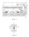
- Figure 2 shows an enlarged section of this coupling training.
- the spherical end face of the pin of the second coupling part 13b is coated with this sliding layer 16, which is in constant contact with the flat surface of the first flat coupling part 13a by means of two springs 17 which are fastened to the scanning unit 7 and to the driver 10.
- the first flat coupling part 13a can also be fastened on the driver 10 and the second spherical coupling part 13b on the scanning unit 7.
- the first flat coupling part 13a can also be integrated in the scanning unit 7, so that the end face of the scanning unit 7 forms the flat surface of the first flat coupling part 13a.
- the sliding layer can also be applied to the flat surface of the first flat coupling part 13a and be in constant contact with the spherical end face of the pin of the second coupling part 13b.
Abstract
Description
Die Erfindung betrifft eine Positionsmeßeinrichtung gemäß dem Oberbegriff des Anspruches 1.The invention relates to a position measuring device according to the preamble of claim 1.
Derartige Positionsmeßeinrichtungen werden insbesondere bei Bearbeitungsmaschinen zur Messung der Relativlage eines Werkzeugs bezüglich eines zu bearbeitenden Werkstücks eingesetzt.Such position measuring devices are used in particular in machine tools for measuring the relative position of a tool with respect to a workpiece to be machined.
Bei Meßeinrichtungen mit einer Abtasteinheit, die an einer von der Führung der beiden Objekte in Form der Maschinenteile unabhängigen Hilfsführung geführt ist, ist eine gelenkige Ankopplung an das zugehörige Objekt bzw. an einen daran angeordneten Mitnehmer unerläßlich.In measuring devices with a scanning unit which is guided on an auxiliary guide which is independent of the guidance of the two objects in the form of the machine parts, an articulated coupling to the associated object or to a driver arranged thereon is essential.
In der DE-PS 26 11 459 ist eine Positionsmeßeinrichtung beschrieben, bei der eine Abtasteinheit zur Abtastung der Teilung eines Teilungsträgers an einer von der Führung der beiden Objekte, deren gegenseitige Relativlage gemessen werden soll, unabhängigen Hilfsführung verschiebbar und an einen Mitnehmer über eine in Meßrichtung steife Kupplung gelenkig angekoppelt ist. Der erste Kupplungsteil dieser Kupplung besteht aus einer Planfläche an der Abtasteinheit, die mit einer sphärischen Fläche des zweiten Kupplungsteils am Mitnehmer mittels einer Feder in ständigem Kontakt steht. Bei dieser Ankopplungsart treten jedoch durch Parallelversatz und Winkelfehler zwischen der Führung der beiden Objekte und der Hilfsführung Relativbewegungen zwischen der Planfläche und der sphärischen Fläche auf, die durch die dabei auftretende Gleitreibung zu einem Verschleiß dieser beiden Kupplungsteile führen und damit Meßungenauigkeiten zur Folge haben, die bei hochpräzisen Positionsmeßeinrichtungen nicht mehr tolerierbar sind.DE-PS 26 11 459 describes a position measuring device in which a scanning unit for scanning the graduation of a graduation carrier one of the guidance of the two objects, the mutual relative position of which is to be measured, is displaceable auxiliary guidance and is articulated to a driver via a coupling which is rigid in the measuring direction. The first coupling part of this coupling consists of a flat surface on the scanning unit, which is in constant contact with a spherical surface of the second coupling part on the driver by means of a spring. In this type of coupling, however, due to parallel misalignment and angular errors between the guidance of the two objects and the auxiliary guidance, relative movements between the plane surface and the spherical surface occur, which lead to wear of these two coupling parts due to the sliding friction occurring, and thus to measurement inaccuracies that result in high-precision position measuring devices are no longer tolerable.
Der Erfindung liegt die Aufgabe zugrunde, bei einer Positionsmeßeinrichtung der genannten Gattung Verschleißerscheinungen zwischen den beiden Kupplungsteilen bei auftretenden gegenseitigen Relativbewegungen und dadurch bedingte Meßungenauigkeiten auszuschließen.The invention has for its object to rule out signs of wear in a position measuring device of the type mentioned between the two coupling parts when mutual relative movements occur and measurement inaccuracies caused thereby.
Diese Aufgabe wird erfindungsgemäß durch das kennzeichnende Merkmal des Anspruches 1 gelöst.This object is achieved by the characterizing feature of claim 1.
Die mit der Erfindung erzielten Vorteile bestehen insbesondere darin, daß durch das Vorsehen einer Gleitschicht zwischen den beiden Kupplungsteilen der Kupplung bei gegenseitigen Relativbewegungen kein meßbarer Verschleiß zwischen den beiden Kupplungsteilen entsteht, so daß keine Meßungenauigkeiten mehr auftreten können.The advantages achieved by the invention consist in particular in that the provision of a sliding layer between the two coupling parts of the coupling results in no measurable wear between the two coupling parts during mutual relative movements, so that measurement inaccuracies can no longer occur.
Vorteilhafte Ausbildungen der Erfindung entnimmt man den Unteransprüchen.Advantageous developments of the invention can be found in the subclaims.
Ein Ausführungsbeispiel der Erfindung wird anhand der Zeichnung näher erläutert.An embodiment of the invention is explained in more detail with reference to the drawing.
Es zeigen
- Figur 1 eine Positionsmeßeinrichtung in einer teilweise geschnittenen Seitenansicht und
Figur 2 einen vergrößerten Ausschnitt einer Kupplungsausbildung.
- Figure 1 is a position measuring device in a partially sectioned side view
- Figure 2 shows an enlarged section of a coupling training.
In Figur 1 ist eine Positionsmeßeinrichtung in einer teilweise geschnittenen Seitenansicht gezeigt, deren Gehäuse 1 an einem Schlitten 2 einer nicht dargestellten Bearbeitungsmaschine in beliebiger Weise befestigt ist. Auf einem Steg 3 im Inneren des Gehäuses 1 ist mittels einer Klebeschicht 4 ein Teilungsträger 5 angebracht, dessen Teilung 6 von einer Abtasteinheit 7 in beliebiger bekannter Weise abgetastet wird.In Figure 1, a position measuring device is shown in a partially sectioned side view, the housing 1 is attached to a
Am Bett 8 der Bearbeitungsmaschine ist mittels Schrauben 9 ein doppelschwertförmiger Mitnehmer 10 befestigt, der durch einen von zwei Dichtlippen 11 verschlossenen Längsschlitz 12 in das Gehäuse 1 hineingreift und über eine Kupplung 13 mit der Abtasteinheit 7 verbunden ist. Die Abtasteinheit 7 ist mittels Rollen 14 auf zwei Oberflächen des Teilungsträgers 5 geführt, die eine von einer Führung 15 des Schlittens 2 bezüglich des Betts 8 unabhängige Hilfsführung für die Abtasteinheit 7 bilden. Der Schlitten 2 und das Bett 8 der Bearbeitungsmaschine stellen die beiden Objekte dar, deren Relativlage in Meßrichtung X gemessen werden soll.A double-sword-
Die Kupplung 13 besteht aus einem ersten Kupplungsteil 13a in Form einer an der Abtasteinheit 7 befestigten ebenen Platte, vorzugsweise aus Hartmetall oder aus poliertem Glas, deren Planfläche senkrecht zur Meßrichtung X verläuft, und aus einem zweiten Kupplungsteil 13b in Form eines am Mitnehmer 10 befestigten, in Meßrichtung x verlaufenden Stiftes mit einer sphärischen Stirnfläche. Zwischen dem ersten ebenen Kupplungsteil 13a und dem zweiten sphärischen Kupplungsteil 13b der Kupplung 13 befindet sich erfindungsgemäß eine Gleitschicht 16 in Form einer dünnen Gleitfolie, beispielsweise mit einer Stärke von 0,1 - 0,2 mm; diese Gleitfolie 16 besteht vorzugsweise aus einem PTFE-haltigen Kunststoff.The coupling 13 consists of a
Figur 2 zeigt einen vergrößerten Ausschnitt dieser Kupplungsausbildung. Die sphärische Stirnfläche des Stiftes des zweiten Kupplungsteils 13b ist mit dieser Gleitschicht 16 überzogen, die mit der Planfläche des ersten ebenen Kupplungsteil 13a durch zwei Federn 17 in ständigem Kontakt steht, die an der Abtasteinheit 7 und am Mitnehmer 10 befestigt sind.Figure 2 shows an enlarged section of this coupling training. The spherical end face of the pin of the
In nicht dargestellter Weise kann auch der erste ebene Kupplungsteils 13a am Mitnehmer 10 und der zweite sphärische Kupplungsteil 13b an der Abtasteinheit 7 befestigt sein. Der erste ebene Kupplungsteil 13a kann auch in der Abtasteinheit 7 integriert sein, so daß die Stirnfläche der Abtasteinheit 7 die Planfläche des ersten ebenen Kupplungsteils 13a bildet.In a manner not shown, the first
In ebenfalls nicht dargestellter Weise kann die Gleitschicht auch auf der Planfläche des ersten ebenen Kupplungteils 13a angebracht sein und mit der sphärischen Stirnfläche des Stiftes des zweiten Kupplungsteils 13b in ständigem Kontakt stehen.In a manner also not shown, the sliding layer can also be applied to the flat surface of the first
Claims (5)
Applications Claiming Priority (2)
| Application Number | Priority Date | Filing Date | Title |
|---|---|---|---|
| DE9006138U | 1990-05-31 | ||
| DE9006138U DE9006138U1 (en) | 1990-05-31 | 1990-05-31 |
Publications (3)
| Publication Number | Publication Date |
|---|---|
| EP0459294A2 true EP0459294A2 (en) | 1991-12-04 |
| EP0459294A3 EP0459294A3 (en) | 1994-02-23 |
| EP0459294B1 EP0459294B1 (en) | 1995-03-01 |
Family
ID=6854261
Family Applications (1)
| Application Number | Title | Priority Date | Filing Date |
|---|---|---|---|
| EP91108310A Expired - Lifetime EP0459294B1 (en) | 1990-05-31 | 1991-05-23 | Position measuring device |
Country Status (5)
| Country | Link |
|---|---|
| US (1) | US5142792A (en) |
| EP (1) | EP0459294B1 (en) |
| JP (1) | JPH04231810A (en) |
| AT (1) | ATE119276T1 (en) |
| DE (2) | DE9006138U1 (en) |
Cited By (2)
| Publication number | Priority date | Publication date | Assignee | Title |
|---|---|---|---|---|
| EP0709655A3 (en) * | 1994-10-25 | 1998-08-12 | Dr. Johannes Heidenhain GmbH | Guidance device |
| EP2037230A1 (en) | 2007-09-15 | 2009-03-18 | Dr. Johannes Heidenhain GmbH | Length measuring device |
Families Citing this family (5)
| Publication number | Priority date | Publication date | Assignee | Title |
|---|---|---|---|---|
| JPH06285731A (en) * | 1992-04-03 | 1994-10-11 | Murata Mach Ltd | Complex working machine |
| US5344610A (en) * | 1993-02-03 | 1994-09-06 | Eastman Kodak Company | Aspirator probe with long pivot arm to minimize tip flick |
| US5273717A (en) * | 1992-09-30 | 1993-12-28 | Eastman Kodak Company | Self-calibrating analyzer aspirator |
| JP4434452B2 (en) | 2000-08-15 | 2010-03-17 | ソニーマニュファクチュアリングシステムズ株式会社 | Measuring device |
| EP3279615B1 (en) * | 2016-08-02 | 2018-10-17 | Dr. Johannes Heidenhain GmbH | Length measuring device |
Citations (3)
| Publication number | Priority date | Publication date | Assignee | Title |
|---|---|---|---|---|
| DE2611459C3 (en) * | 1976-03-18 | 1978-09-21 | Dr. Johannes Heidenhain Gmbh, 8225 Traunreut | Length measuring device |
| DE3215334C1 (en) * | 1982-04-24 | 1983-06-09 | Dr. Johannes Heidenhain Gmbh, 8225 Traunreut | Encapsulated measuring device |
| DE3415514A1 (en) * | 1984-04-26 | 1985-11-07 | Dr. Johannes Heidenhain Gmbh, 8225 Traunreut | PROTECTIVE DEVICE FOR LENGTH MEASURING DEVICES |
Family Cites Families (11)
| Publication number | Priority date | Publication date | Assignee | Title |
|---|---|---|---|---|
| US3816002A (en) * | 1972-10-10 | 1974-06-11 | H Wieg | Apparatus for measuring displacement between two relatively movable members |
| US3816003A (en) * | 1973-03-12 | 1974-06-11 | Dynamics Res Corp | Sealed linear encoder |
| US3942895A (en) * | 1973-09-04 | 1976-03-09 | Teledyne, Inc. | Linear digital readout assembly for milling machines and the like and means for mounting same |
| JPS50127653A (en) * | 1974-03-27 | 1975-10-07 | ||
| US4215480A (en) * | 1977-12-16 | 1980-08-05 | James Neill Holdings Limited | Distance measuring gauge |
| DE2820753C2 (en) * | 1978-05-12 | 1980-03-06 | Dr. Johannes Heidenhain Gmbh, 8225 Traunreut | Device for correcting errors in position measuring systems |
| JPS5724484A (en) * | 1980-07-22 | 1982-02-09 | Kayaba Ind Co Ltd | Vane pump |
| DE3208591C2 (en) * | 1982-03-10 | 1986-06-05 | Dr. Johannes Heidenhain Gmbh, 8225 Traunreut | Digital electrical length or angle measuring system |
| DE3311562C1 (en) * | 1983-03-30 | 1984-05-24 | Dr. Johannes Heidenhain Gmbh, 8225 Traunreut | Measuring system with a device for error correction |
| DD243757A1 (en) * | 1985-12-02 | 1987-03-11 | Zeiss Jena Veb Carl | PRAEZISIONSLAENGENMESSSYSTEM |
| AT394110B (en) * | 1989-02-10 | 1992-02-10 | Rsf Elektronik Gmbh | LENGTH MEASURING SYSTEM |
-
1990
- 1990-05-31 DE DE9006138U patent/DE9006138U1/de not_active Expired - Lifetime
-
1991
- 1991-05-17 US US07/702,223 patent/US5142792A/en not_active Expired - Lifetime
- 1991-05-23 AT AT91108310T patent/ATE119276T1/en not_active IP Right Cessation
- 1991-05-23 DE DE59104745T patent/DE59104745D1/en not_active Expired - Fee Related
- 1991-05-23 EP EP91108310A patent/EP0459294B1/en not_active Expired - Lifetime
- 1991-05-29 JP JP3126204A patent/JPH04231810A/en active Pending
Patent Citations (3)
| Publication number | Priority date | Publication date | Assignee | Title |
|---|---|---|---|---|
| DE2611459C3 (en) * | 1976-03-18 | 1978-09-21 | Dr. Johannes Heidenhain Gmbh, 8225 Traunreut | Length measuring device |
| DE3215334C1 (en) * | 1982-04-24 | 1983-06-09 | Dr. Johannes Heidenhain Gmbh, 8225 Traunreut | Encapsulated measuring device |
| DE3415514A1 (en) * | 1984-04-26 | 1985-11-07 | Dr. Johannes Heidenhain Gmbh, 8225 Traunreut | PROTECTIVE DEVICE FOR LENGTH MEASURING DEVICES |
Cited By (3)
| Publication number | Priority date | Publication date | Assignee | Title |
|---|---|---|---|---|
| EP0709655A3 (en) * | 1994-10-25 | 1998-08-12 | Dr. Johannes Heidenhain GmbH | Guidance device |
| EP2037230A1 (en) | 2007-09-15 | 2009-03-18 | Dr. Johannes Heidenhain GmbH | Length measuring device |
| DE102007044128A1 (en) | 2007-09-15 | 2009-03-19 | Dr. Johannes Heidenhain Gmbh | Length measuring device |
Also Published As
| Publication number | Publication date |
|---|---|
| JPH04231810A (en) | 1992-08-20 |
| EP0459294A3 (en) | 1994-02-23 |
| US5142792A (en) | 1992-09-01 |
| EP0459294B1 (en) | 1995-03-01 |
| DE9006138U1 (en) | 1990-08-02 |
| ATE119276T1 (en) | 1995-03-15 |
| DE59104745D1 (en) | 1995-04-06 |
Similar Documents
| Publication | Publication Date | Title |
|---|---|---|
| DE3201887C2 (en) | Length measuring device | |
| EP2037230B1 (en) | Length measuring device | |
| DE2810341B1 (en) | Length measuring device | |
| EP0126937B1 (en) | Length measuring device | |
| EP1041363A2 (en) | Procedure and device to mount a measuring scale on a substrate | |
| EP0459294B1 (en) | Position measuring device | |
| DE2643304A1 (en) | Photo-electric arrangement measuring relative positions of objects - has measuring scale coupled to one object by profile and reading-off panel opposite | |
| EP0018657A1 (en) | Set-square for dividing angles and tracing parallels | |
| DE19700367C2 (en) | Method and assembly device for the directed application of a measuring tape | |
| EP0465966B1 (en) | Measuring scale | |
| EP0253992B1 (en) | Position-measuring device | |
| DE10229885B4 (en) | Method and apparatus for attaching a scale or scale carrier or scale guide | |
| EP0387488B1 (en) | Position measuring device | |
| DE3434993A1 (en) | Caliper | |
| AT408729B (en) | TOOL CLAMPING DEVICE FOR A MOLDING TOOL, IN PARTICULAR A BENDING PRESS | |
| EP0218836B1 (en) | Slideway | |
| EP3705850A1 (en) | Assembly with a main beam, an intermediate support arranged on the main beam and a measuring rod on the intermediate support | |
| EP0805954B1 (en) | Length measuring apparatus for measuring the relative position of two objects | |
| EP4030147A1 (en) | Length measuring device | |
| DE3311562C1 (en) | Measuring system with a device for error correction | |
| EP0733882A1 (en) | Position-measuring device | |
| DE19504770C1 (en) | Measuring rule marking aid | |
| DE3409298C1 (en) | Position-measuring device | |
| DE8201438U1 (en) | Length measuring device | |
| EP0171562A2 (en) | Position-measuring device |
Legal Events
| Date | Code | Title | Description |
|---|---|---|---|
| PUAI | Public reference made under article 153(3) epc to a published international application that has entered the european phase |
Free format text: ORIGINAL CODE: 0009012 |
|
| 17P | Request for examination filed |
Effective date: 19910607 |
|
| AK | Designated contracting states |
Kind code of ref document: A2 Designated state(s): AT CH DE FR GB IT LI |
|
| PUAL | Search report despatched |
Free format text: ORIGINAL CODE: 0009013 |
|
| AK | Designated contracting states |
Kind code of ref document: A3 Designated state(s): AT CH DE FR GB IT LI |
|
| 17Q | First examination report despatched |
Effective date: 19940728 |
|
| ITF | It: translation for a ep patent filed |
Owner name: DE DOMINICIS & MAYER S.R.L. |
|
| GRAA | (expected) grant |
Free format text: ORIGINAL CODE: 0009210 |
|
| AK | Designated contracting states |
Kind code of ref document: B1 Designated state(s): AT CH DE FR GB IT LI |
|
| REF | Corresponds to: |
Ref document number: 119276 Country of ref document: AT Date of ref document: 19950315 Kind code of ref document: T |
|
| ET | Fr: translation filed | ||
| GBT | Gb: translation of ep patent filed (gb section 77(6)(a)/1977) |
Effective date: 19950227 |
|
| REF | Corresponds to: |
Ref document number: 59104745 Country of ref document: DE Date of ref document: 19950406 |
|
| PLBE | No opposition filed within time limit |
Free format text: ORIGINAL CODE: 0009261 |
|
| STAA | Information on the status of an ep patent application or granted ep patent |
Free format text: STATUS: NO OPPOSITION FILED WITHIN TIME LIMIT |
|
| 26N | No opposition filed | ||
| PGFP | Annual fee paid to national office [announced via postgrant information from national office to epo] |
Ref country code: GB Payment date: 20010412 Year of fee payment: 11 |
|
| PGFP | Annual fee paid to national office [announced via postgrant information from national office to epo] |
Ref country code: CH Payment date: 20010418 Year of fee payment: 11 |
|
| PGFP | Annual fee paid to national office [announced via postgrant information from national office to epo] |
Ref country code: AT Payment date: 20010427 Year of fee payment: 11 |
|
| PGFP | Annual fee paid to national office [announced via postgrant information from national office to epo] |
Ref country code: FR Payment date: 20010507 Year of fee payment: 11 |
|
| REG | Reference to a national code |
Ref country code: GB Ref legal event code: IF02 |
|
| PG25 | Lapsed in a contracting state [announced via postgrant information from national office to epo] |
Ref country code: AT Free format text: LAPSE BECAUSE OF NON-PAYMENT OF DUE FEES Effective date: 20020523 Ref country code: GB Free format text: LAPSE BECAUSE OF NON-PAYMENT OF DUE FEES Effective date: 20020523 |
|
| PG25 | Lapsed in a contracting state [announced via postgrant information from national office to epo] |
Ref country code: CH Free format text: LAPSE BECAUSE OF NON-PAYMENT OF DUE FEES Effective date: 20020531 Ref country code: LI Free format text: LAPSE BECAUSE OF NON-PAYMENT OF DUE FEES Effective date: 20020531 |
|
| GBPC | Gb: european patent ceased through non-payment of renewal fee |
Effective date: 20020523 |
|
| REG | Reference to a national code |
Ref country code: CH Ref legal event code: PL |
|
| PG25 | Lapsed in a contracting state [announced via postgrant information from national office to epo] |
Ref country code: FR Free format text: LAPSE BECAUSE OF NON-PAYMENT OF DUE FEES Effective date: 20030131 |
|
| REG | Reference to a national code |
Ref country code: FR Ref legal event code: ST |
|
| PG25 | Lapsed in a contracting state [announced via postgrant information from national office to epo] |
Ref country code: IT Free format text: LAPSE BECAUSE OF NON-PAYMENT OF DUE FEES;WARNING: LAPSES OF ITALIAN PATENTS WITH EFFECTIVE DATE BEFORE 2007 MAY HAVE OCCURRED AT ANY TIME BEFORE 2007. THE CORRECT EFFECTIVE DATE MAY BE DIFFERENT FROM THE ONE RECORDED. Effective date: 20050523 |
|
| PGFP | Annual fee paid to national office [announced via postgrant information from national office to epo] |
Ref country code: DE Payment date: 20080523 Year of fee payment: 18 |
|
| PG25 | Lapsed in a contracting state [announced via postgrant information from national office to epo] |
Ref country code: DE Free format text: LAPSE BECAUSE OF NON-PAYMENT OF DUE FEES Effective date: 20091201 |