EP0459080A2 - Optical pickup for reproducing data on a disk - Google Patents
Optical pickup for reproducing data on a disk Download PDFInfo
- Publication number
- EP0459080A2 EP0459080A2 EP91101356A EP91101356A EP0459080A2 EP 0459080 A2 EP0459080 A2 EP 0459080A2 EP 91101356 A EP91101356 A EP 91101356A EP 91101356 A EP91101356 A EP 91101356A EP 0459080 A2 EP0459080 A2 EP 0459080A2
- Authority
- EP
- European Patent Office
- Prior art keywords
- base
- optical pickup
- secured
- yoke
- pair
- Prior art date
- Legal status (The legal status is an assumption and is not a legal conclusion. Google has not performed a legal analysis and makes no representation as to the accuracy of the status listed.)
- Withdrawn
Links
Images


Classifications
-
- G—PHYSICS
- G11—INFORMATION STORAGE
- G11B—INFORMATION STORAGE BASED ON RELATIVE MOVEMENT BETWEEN RECORD CARRIER AND TRANSDUCER
- G11B7/00—Recording or reproducing by optical means, e.g. recording using a thermal beam of optical radiation by modifying optical properties or the physical structure, reproducing using an optical beam at lower power by sensing optical properties; Record carriers therefor
- G11B7/08—Disposition or mounting of heads or light sources relatively to record carriers
- G11B7/09—Disposition or mounting of heads or light sources relatively to record carriers with provision for moving the light beam or focus plane for the purpose of maintaining alignment of the light beam relative to the record carrier during transducing operation, e.g. to compensate for surface irregularities of the latter or for track following
- G11B7/0925—Electromechanical actuators for lens positioning
- G11B7/0933—Details of stationary parts
-
- G—PHYSICS
- G11—INFORMATION STORAGE
- G11B—INFORMATION STORAGE BASED ON RELATIVE MOVEMENT BETWEEN RECORD CARRIER AND TRANSDUCER
- G11B7/00—Recording or reproducing by optical means, e.g. recording using a thermal beam of optical radiation by modifying optical properties or the physical structure, reproducing using an optical beam at lower power by sensing optical properties; Record carriers therefor
- G11B7/08—Disposition or mounting of heads or light sources relatively to record carriers
- G11B7/09—Disposition or mounting of heads or light sources relatively to record carriers with provision for moving the light beam or focus plane for the purpose of maintaining alignment of the light beam relative to the record carrier during transducing operation, e.g. to compensate for surface irregularities of the latter or for track following
- G11B7/0925—Electromechanical actuators for lens positioning
- G11B7/0932—Details of sprung supports
Definitions
- the present invention relates to an optical pickup for reproducing data on a disk such as a compact disk (CD) and a laser disk (LD).
- a disk such as a compact disk (CD) and a laser disk (LD).
- Fig. 3 shows a conventional optical pickup.
- the optical pickup comprises a holder 16 having a coil substrate 15a for focusing and a coil substrate 15b for tracking, a print circuit board 20, and a base plate 22.
- the holder has an optical system 16a.
- the holder 16 is suspended from the print circuit board 20 by four conductive wires 14 in the form of a cantilever.
- the circuit board 20 is secured to a supporting member 22a on the base plate 22 by a screw 23 through a connecting member 21 of plastic.
- a pair of yokes 11a each having a magnet 12a are mounted on the base plate 22.
- the holder 16 is disposed between the yokes 11a so as to oppose the coil substrates 15a and 15b to the yokes, respectively.
- the print circuit board 20 is connected to a head substrate 24 through a flexible wiring plate 17a with solder.
- An exciting current is supplied to the coil substrates 15a and 15b through the conductive wires 14 for moving the holder
- the object of the present invention is to provide an optical pickup which may be reduced in size and can be easily assembled at low cost.
- an optical pickup comprising, a yoke base, a pair of yokes mounted on the yoke base, each of the yokes having a magnet, a suspension base made of plastic having terminals embedded therein and secured to the yoke base, a holder having an optical system and a pair of coil substrates for focusing and tracking the optical system and suspended from the suspension base by conductive wires, the coil substrates being disposed between the magnets, and a circuit substrate secured to the yoke base, each of the terminals being soldered to an end of a corresponding wire on the circuit substrate.
- the conductive wires are four in number, and exciting current is supplied to the coil substrates through the conductive wires.
- the optical pickup comprises the holder 16, a suspension base 13, a yoke base 10, and a circuit substrate 18.
- the holder 16 has an optical system 16a and a pair of coil substrates 15a and 15b. On each coil substrate, an exciting coil (not shown) is mounted.
- the holder 16 is suspended from the suspension base 13 made of plastic by four conductive spring wires 14 in the form of a cantilever. Four terminals 13e each connected to the conductive wire 14 are embedded in the suspension base 13 by insert molding.
- the yoke base 10 has a pair of yokes 11, each having a magnet 12.
- the yoke base 10 is secured to the underside of the suspension base 13 by a screw 13b engaged with a hole 13a of the base 13 and a hole 10c formed in the yoke base 10. Both the magnets 12 are positioned adjacent the coil substrates 15a and 15b, respectively.
- the circuit substrate 18 has an attaching plate 18b having a hole 18a and a pair of terminal portions 18e.
- the circuit substrate 18 is secured to the yoke base 10 by a screw (not shown) engaged with a hole 10a formed in an attaching plate 10b of the yoke base 10 and in the hole 18a.
- the holder 16, suspension base 13, yoke base 10 and circuit substrate 18 are separately assembled.
- the circuit substrate 18 is secured to the yoke base 10 by engaging a screw with the hole 10a and the hole 18a.
- the suspension base 13 is secured to the yoke base 10 by engaging the screw 13b with the hole 13a of the suspension base 13 and the hole 10c of the yoke base 10.
- each of the terminals 13e is soldered to an end of a corresponding wire 18d.
- the suspension base 13 is made of plastic and the terminals 13e are embedded by insert molding. Consequently, the number of parts is reduced and soldering operation is simplified. Accordingly, the optical pickup can be easily manufactured at a low cost.
Landscapes
- Optical Recording Or Reproduction (AREA)
- Optical Head (AREA)
Abstract
Description
- The present invention relates to an optical pickup for reproducing data on a disk such as a compact disk (CD) and a laser disk (LD).
- Fig. 3 shows a conventional optical pickup. The optical pickup comprises a
holder 16 having acoil substrate 15a for focusing and acoil substrate 15b for tracking, aprint circuit board 20, and abase plate 22. The holder has an optical system 16a. Theholder 16 is suspended from theprint circuit board 20 by fourconductive wires 14 in the form of a cantilever. Thecircuit board 20 is secured to a supporting member 22a on thebase plate 22 by ascrew 23 through a connectingmember 21 of plastic. A pair ofyokes 11a each having amagnet 12a are mounted on thebase plate 22. Theholder 16 is disposed between theyokes 11a so as to oppose thecoil substrates print circuit board 20 is connected to ahead substrate 24 through a flexible wiring plate 17a with solder. An exciting current is supplied to thecoil substrates conductive wires 14 for moving theholder 16 in the focusing direction and the tracking direction. - In such a pickup, the number of parts of the pickup is large and assembling of the pickup is complicated. Hence, it is difficult to lower the cost of the pickup and to reduce the size thereof.
- The object of the present invention is to provide an optical pickup which may be reduced in size and can be easily assembled at low cost.
- According to the present invention, there is provided an optical pickup comprising, a yoke base, a pair of yokes mounted on the yoke base, each of the yokes having a magnet, a suspension base made of plastic having terminals embedded therein and secured to the yoke base, a holder having an optical system and a pair of coil substrates for focusing and tracking the optical system and suspended from the suspension base by conductive wires, the coil substrates being disposed between the magnets, and a circuit substrate secured to the yoke base, each of the terminals being soldered to an end of a corresponding wire on the circuit substrate.
- In an aspect of the invention, the conductive wires are four in number, and exciting current is supplied to the coil substrates through the conductive wires.
- The other objects and features of this invention will become understood from the following description with reference to the accompanying drawings.
- Fig. 1 is a perspective view of an optical pickup according to the present invention;
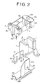
- Fig. 2 is an exploded perspective view of the optical pickup; and
- Fig. 3 is a conventional optical pickup.
- Referring to Figs. 1 and 2, the optical pickup according to the present invention comprises the
holder 16, asuspension base 13, ayoke base 10, and acircuit substrate 18. Theholder 16 has an optical system 16a and a pair ofcoil substrates holder 16 is suspended from thesuspension base 13 made of plastic by fourconductive spring wires 14 in the form of a cantilever. Fourterminals 13e each connected to theconductive wire 14 are embedded in thesuspension base 13 by insert molding. Theyoke base 10 has a pair of yokes 11, each having amagnet 12. Theyoke base 10 is secured to the underside of thesuspension base 13 by a screw 13b engaged with a hole 13a of thebase 13 and a hole 10c formed in theyoke base 10. Both themagnets 12 are positioned adjacent thecoil substrates - The
circuit substrate 18 has an attaching plate 18b having ahole 18a and a pair ofterminal portions 18e. Thecircuit substrate 18 is secured to theyoke base 10 by a screw (not shown) engaged with a hole 10a formed in an attaching plate 10b of theyoke base 10 and in thehole 18a. - Assembling of the optical pickup is performed as follows.
- The
holder 16,suspension base 13,yoke base 10 andcircuit substrate 18 are separately assembled. Thecircuit substrate 18 is secured to theyoke base 10 by engaging a screw with the hole 10a and thehole 18a. Thesuspension base 13 is secured to theyoke base 10 by engaging the screw 13b with the hole 13a of thesuspension base 13 and the hole 10c of theyoke base 10. Finally, each of theterminals 13e is soldered to an end of acorresponding wire 18d. - In accordance with the present invention, the
suspension base 13 is made of plastic and theterminals 13e are embedded by insert molding. Consequently, the number of parts is reduced and soldering operation is simplified. Accordingly, the optical pickup can be easily manufactured at a low cost. - While the presently preferred embodiment of the present invention has been shown and described, it is to be understood that this disclosure is for the purpose of illustration and that various changes and modifications may be made without departing from the scope of the invention as set forth in the appended claims.
Claims (2)
- An optical pickup comprising:
a yoke base (10);
a pair of yokes (11) mounted on the yoke base (10),
each of the yokes (11) having a magnet (12);
a suspension base (13) made of plastic having terminals (13e) embedded therein and secured to the yoke base (10);
a holder (16) having an optical system (16a) and a pair of coil substrates (15a, 15b) for focusing and tracking the optical system (16a) and suspended from the suspension base (13) by conductive wires (14);
the coil substrates (15a, 15b) being disposed between the magnets (12);
a circuit substrate (18) secured to the yoke base (10);
and each of the terminals (13e) being soldered to an end of a corresponding wire (18e) on the circuit substrate (18). - The optical pickup according to claim 1 wherein the conductive wires (14) are four in number, and exiting current is supplied to the coil substrates (15a, 15b) through the conductive wires (14).
Applications Claiming Priority (2)
| Application Number | Priority Date | Filing Date | Title |
|---|---|---|---|
| JP135726/90 | 1990-05-26 | ||
| JP2135726A JP3048243B2 (en) | 1990-05-26 | 1990-05-26 | Optical pickup |
Publications (2)
| Publication Number | Publication Date |
|---|---|
| EP0459080A2 true EP0459080A2 (en) | 1991-12-04 |
| EP0459080A3 EP0459080A3 (en) | 1992-04-29 |
Family
ID=15158449
Family Applications (1)
| Application Number | Title | Priority Date | Filing Date |
|---|---|---|---|
| EP19910101356 Withdrawn EP0459080A3 (en) | 1990-05-26 | 1991-02-01 | Optical pickup for reproducing data on a disk |
Country Status (2)
| Country | Link |
|---|---|
| EP (1) | EP0459080A3 (en) |
| JP (1) | JP3048243B2 (en) |
Cited By (3)
| Publication number | Priority date | Publication date | Assignee | Title |
|---|---|---|---|---|
| EP0660312A1 (en) * | 1993-12-22 | 1995-06-28 | Sony Corporation | Objective lens drive device and coil bobbin thereof |
| US5555228A (en) * | 1993-11-16 | 1996-09-10 | Sony Corporation | An optical head having a vertical flat plate shaped magnetic circuit containing a tracking coil and a focusing coil |
| US5581533A (en) * | 1993-10-30 | 1996-12-03 | Sony Corporation | Objective lens actuating device, optical pickup employing the objective lens actuating device and optical disk recording and/or reproducing apparatus employing such optical pickup |
Citations (2)
| Publication number | Priority date | Publication date | Assignee | Title |
|---|---|---|---|---|
| JPS6020324A (en) * | 1983-07-14 | 1985-02-01 | Copal Co Ltd | Actuator device of pickup |
| EP0144445A1 (en) * | 1983-05-31 | 1985-06-19 | Matsushita Electric Industrial Co., Ltd. | Apparatus for driving objective lens of optical disc player |
-
1990
- 1990-05-26 JP JP2135726A patent/JP3048243B2/en not_active Expired - Lifetime
-
1991
- 1991-02-01 EP EP19910101356 patent/EP0459080A3/en not_active Withdrawn
Patent Citations (2)
| Publication number | Priority date | Publication date | Assignee | Title |
|---|---|---|---|---|
| EP0144445A1 (en) * | 1983-05-31 | 1985-06-19 | Matsushita Electric Industrial Co., Ltd. | Apparatus for driving objective lens of optical disc player |
| JPS6020324A (en) * | 1983-07-14 | 1985-02-01 | Copal Co Ltd | Actuator device of pickup |
Non-Patent Citations (1)
| Title |
|---|
| PATENT ABSTRACTS OF JAPAN, vol. 9, no. 141 (P-364)[1864], 15th June 1985; & JP-A-60 20 324 (COPAL) 01-02-1985 * |
Cited By (5)
| Publication number | Priority date | Publication date | Assignee | Title |
|---|---|---|---|---|
| US5581533A (en) * | 1993-10-30 | 1996-12-03 | Sony Corporation | Objective lens actuating device, optical pickup employing the objective lens actuating device and optical disk recording and/or reproducing apparatus employing such optical pickup |
| CN1084014C (en) * | 1993-10-30 | 2002-05-01 | 索尼公司 | Objective lens actuating device, optical pickup employing the objective lens actuating device and optical disc recording and/or reproducing apparatus employing such optical pickup |
| US5555228A (en) * | 1993-11-16 | 1996-09-10 | Sony Corporation | An optical head having a vertical flat plate shaped magnetic circuit containing a tracking coil and a focusing coil |
| EP0660312A1 (en) * | 1993-12-22 | 1995-06-28 | Sony Corporation | Objective lens drive device and coil bobbin thereof |
| US5535059A (en) * | 1993-12-22 | 1996-07-09 | Sony Corporation | Objective lens drive device and coil bobbin thereof |
Also Published As
| Publication number | Publication date |
|---|---|
| EP0459080A3 (en) | 1992-04-29 |
| JPH0430340A (en) | 1992-02-03 |
| JP3048243B2 (en) | 2000-06-05 |
Similar Documents
| Publication | Publication Date | Title |
|---|---|---|
| US5926327A (en) | Objective lens driving device for an optical pick-up unit | |
| JP3208751B2 (en) | Optical pickup | |
| US6880165B2 (en) | Objective lens driving unit with connecting members displaced in extending direction of suspension wires | |
| EP0459080A2 (en) | Optical pickup for reproducing data on a disk | |
| EP0459088B1 (en) | Optical pickup with supporting device | |
| EP0459087B1 (en) | Optical pickup for reproducing data on a disc | |
| US5694258A (en) | Optical pickup and optical recording and reproduction apparatus | |
| US6519100B1 (en) | Optical pick-up apparatus | |
| KR100486267B1 (en) | An optical pickup actuator and an optical disk drive using the same | |
| JPH1145453A (en) | Optical pickup | |
| JP2712640B2 (en) | Optical pickup | |
| JP2793786B2 (en) | Objective lens driving device for optical disk device and method of manufacturing the same | |
| JP3306197B2 (en) | Objective lens drive | |
| JPH0419615Y2 (en) | ||
| JP2514471B2 (en) | Optical pickup | |
| JPH11120584A (en) | Objective lens drive unit | |
| JPH11120600A (en) | Optical pickup device | |
| JP2877568B2 (en) | Objective lens support device | |
| JP2679018B2 (en) | Objective lens support device | |
| JP2571323Y2 (en) | Objective lens drive | |
| JPH11144272A (en) | Lens holder support structure for optical pickup | |
| JPH04209333A (en) | Light pickup | |
| JPH08194957A (en) | Optical pickup | |
| JPH05128586A (en) | Assembling method for objective lens supporting device | |
| JPH09134535A (en) | Apparatus for driving objective lens |
Legal Events
| Date | Code | Title | Description |
|---|---|---|---|
| PUAI | Public reference made under article 153(3) epc to a published international application that has entered the european phase |
Free format text: ORIGINAL CODE: 0009012 |
|
| AK | Designated contracting states |
Kind code of ref document: A2 Designated state(s): DE FR GB |
|
| 17P | Request for examination filed |
Effective date: 19911126 |
|
| PUAL | Search report despatched |
Free format text: ORIGINAL CODE: 0009013 |
|
| AK | Designated contracting states |
Kind code of ref document: A3 Designated state(s): DE FR GB |
|
| 17Q | First examination report despatched |
Effective date: 19940923 |
|
| STAA | Information on the status of an ep patent application or granted ep patent |
Free format text: STATUS: THE APPLICATION IS DEEMED TO BE WITHDRAWN |
|
| 18D | Application deemed to be withdrawn |
Effective date: 19950404 |