EP0458985B1 - An electric welding robot and a method for welding by using the robot - Google Patents
An electric welding robot and a method for welding by using the robot Download PDFInfo
- Publication number
- EP0458985B1 EP0458985B1 EP91900932A EP91900932A EP0458985B1 EP 0458985 B1 EP0458985 B1 EP 0458985B1 EP 91900932 A EP91900932 A EP 91900932A EP 91900932 A EP91900932 A EP 91900932A EP 0458985 B1 EP0458985 B1 EP 0458985B1
- Authority
- EP
- European Patent Office
- Prior art keywords
- arm
- welding
- rotating
- axis
- rotating arm
- Prior art date
- Legal status (The legal status is an assumption and is not a legal conclusion. Google has not performed a legal analysis and makes no representation as to the accuracy of the status listed.)
- Expired - Lifetime
Links
Images

Classifications
-
- B—PERFORMING OPERATIONS; TRANSPORTING
- B23—MACHINE TOOLS; METAL-WORKING NOT OTHERWISE PROVIDED FOR
- B23K—SOLDERING OR UNSOLDERING; WELDING; CLADDING OR PLATING BY SOLDERING OR WELDING; CUTTING BY APPLYING HEAT LOCALLY, e.g. FLAME CUTTING; WORKING BY LASER BEAM
- B23K9/00—Arc welding or cutting
- B23K9/24—Features related to electrodes
- B23K9/28—Supporting devices for electrodes
- B23K9/287—Supporting devices for electrode holders
-
- B—PERFORMING OPERATIONS; TRANSPORTING
- B23—MACHINE TOOLS; METAL-WORKING NOT OTHERWISE PROVIDED FOR
- B23K—SOLDERING OR UNSOLDERING; WELDING; CLADDING OR PLATING BY SOLDERING OR WELDING; CUTTING BY APPLYING HEAT LOCALLY, e.g. FLAME CUTTING; WORKING BY LASER BEAM
- B23K9/00—Arc welding or cutting
- B23K9/12—Automatic feeding or moving of electrodes or work for spot or seam welding or cutting
-
- B—PERFORMING OPERATIONS; TRANSPORTING
- B25—HAND TOOLS; PORTABLE POWER-DRIVEN TOOLS; MANIPULATORS
- B25J—MANIPULATORS; CHAMBERS PROVIDED WITH MANIPULATION DEVICES
- B25J9/00—Programme-controlled manipulators
- B25J9/02—Programme-controlled manipulators characterised by movement of the arms, e.g. cartesian coordinate type
- B25J9/04—Programme-controlled manipulators characterised by movement of the arms, e.g. cartesian coordinate type by rotating at least one arm, excluding the head movement itself, e.g. cylindrical coordinate type or polar coordinate type
- B25J9/041—Cylindrical coordinate type
- B25J9/042—Cylindrical coordinate type comprising an articulated arm
Definitions
- the present invention relates to an electric welding robot comprising a plurality of arms articulated with one another and to a method for welding by using the welding robot.
- a welding robot which has a plurality of rotating arms articulated with one another to move its welding electrode horizontally and vertically.
- positioning of the electrode at desired locations is controlled by rotating or moving the said arms independently by respective motors.
- a welding robot according to the preamble of claim 1 is known from FR-A-2627114.
- This known welding root has a protecting arm, a first rotating arm, a first driving means for rotating this rotating arm and a second rotating arm, rotated by an actuator.
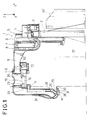
- Fig. 1 is a side view of an electric welding robot according to the present invention.
- Fig. 2 is a top plan view of the electric welding robot shown in Fig. 1.
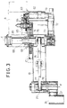
- Fig. 3 is a partially sectional side view showing means for rotating two rotating arms of the welding robot.
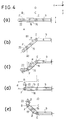
- Fig. 4 is explanatory drawings to show movements of three arms of the welding robot.
- a welding robot 1 in Figs. 1 and 2, there is shown a welding robot 1 according to the present invention.
- the welding robot 1 includes an electronic control unit 40 and a support 2.
- the support 2 carries at its top a rectilinear guide beam 3 disposed parallel to the X axis.
- a slide 4 is mounted slidably on the guide beam 3.
- the slide 4 is driven by a driving unit 5 of known type.
- the slide 4 fixedly carries a pair of vertical guides 6 parallel to the Z axis, along which slides a second slide 7 by means of another driving unit 8 also of known type.
- the slide 7 is provided with a projecting arm 9.
- a first rotating arm 19 is pivoted at its one end by means of a shaft 68 with an end of the projecting arm 9.
- the first rotating arm 19 is rotated about a first vertical axis E of the shaft 68 by first means 20 including a motor 62 supported by the projecting arm 9, a gear 63 of the motor 62, a plurality of transmission gears 64, and a gear 65 of the shaft 68.
- the gear 65 is fixed to the shaft 68 which is rotatably supported in the arm 9.
- the gear 65 is also fixed to the arm 19 with connecting members 69.
- a second rotating arm 22, which is short, is pivoted at its one end by means of a shaft 78 with another end of the first rotating arm 19.
- the shaft 78 is rotatably supported in the first arm 19.
- the axis of the shaft 74 is matched with the first vertical axis E of the shaft 68 which connects these two arms 9, 19 with each other through the gear 65.
- the shaft 74 is supported and rotatable freely in the first arm 19 and is provided with a toothed pulley 75 fixed to it at its one end and at the other end connected to a motor 72 through worm gears 73.
- the motor 72 is fixed to the projecting arm 9 with connecting means 79 to prevent its rotation about the first vertical axis E.
- the shaft 78 is also provided with a toothed pulley 77 fixed to it.
- a toothed belt 76 is disposed between two pulleys 77 and 75 to transmit the rotation of the motor 72 when it is driven.
- One end of the second rotating arm 22 is fixed to the bottom part of the shaft 78, and therefore the arm 22 can be rotated about an axis F with reference to the first arm 19 by second means 23 comprising the motor 72, worm gears 73, shafts 74, 78, the toothed belt 76 and the toothed pulleys 75, 77.
- the second rotating arm 22 is rotated about the second vertical axis F in the opposite direction (clockwise) mechanically and automatically by a synchronized function of the second means 23 when the first rotating arm 19 is rotated forcibly by the first means 20 about the first vertical axis E in a direction (anti-clockwise) as shown in Fig. 4c, if the motor 72 of the second means 23 is disactivated and also fixed not to rotate about the first vertical axis E and therefore the shaft 74 is fixed there without rotating notwithstanding the rotation of the first rotating arm 19.
- the second rotating arm 22 fixedly carries a columnar arm 24 which extends from the said end downwards parallel to the Z axis (Fig. 1).
- a fork 25 which carries a head 26 on an axis H which is perpendicular to the axis F.
- the head 26 can be rotated about the axis H, by means of an angular position driving unit 28.
- the head 26 carries a rectilinear welding electrode 29 which extends from the head 26 and terminates with an end 30 which is exactly on the projection line of the axis F when the electrode 29 is disposed perpendicularly to the axis F itself.
- the head 26 is further provided with a laser vision sensor 31 which can turn about electrode 29, and which is orientated with its field of vision in a region close to the top end 30 of the electrode 29, conveniently as described in FR-A-2 627 114 and the contents of which are incorporated herein by reference.
- a laser vision sensor 31 which can turn about electrode 29, and which is orientated with its field of vision in a region close to the top end 30 of the electrode 29, conveniently as described in FR-A-2 627 114 and the contents of which are incorporated herein by reference.
- Fig. 4a is a simplified plan of the welding robot of Figs. 1 and 2. Three arms 9, 19, 22 are now aligned in a line. The top end 30 of the electrode 29 is just on the projection line of the axis F (Fig. 1), and the electrode 29 extends perpendicularly to a dotted line A-B. When a welding is necessary for an object 37 along the dotted line A-B it is easily carried out by moving the projecting arm 9 horizontally along the guide beam 3.
- the welding line A-B lies on a line A1-B1 as shown in Fig. 4b, it is difficult to carry out the welding by a conventional welding robot, because rotations and/or movements for all arms must be controlled. However, it is carried out easily by the robot of the present invention.
- the first rotating arm 19 is rotated anti-clockwise about the first vertical axis E through an angle of ⁇ .
- the second rotating arm 22 would move together with the first arm 19 as shown in Fig. 4b if the welding robot 1 is not provided with the second means 23, or the motor 72 is allowed to rotate about the first vertical axis E.
- the projecting arm 9 is moved horizontally by a distance d, and the welding is initiated with rotating of the first arm 19 and/or moving of the projecting arm 9.
- the second arm 22 When a welding is necessary along a line B-C shown in Fig. 4d, the second arm 22 is rotated through a desired angle by activating the motor 72 so that the electrode 29 faces in a direction perpendicular to the line B-C, and the first arm 19 is rotated through a desired angle of ⁇ (Fig. 4e) by the first means 20. At this time, the second arm 22 is held automatically with the electrode 29 facing in the same direction perpendicular to the welding line B-C.
Abstract
Description
- The present invention relates to an electric welding robot comprising a plurality of arms articulated with one another and to a method for welding by using the welding robot.
- In the prior art known is a welding robot, which has a plurality of rotating arms articulated with one another to move its welding electrode horizontally and vertically.
- For the welding robot of the prior art, positioning of the electrode at desired locations is controlled by rotating or moving the said arms independently by respective motors.
- However, it is difficult to control the said arms at the same time for welding in a particular direction, and therefore it requires special controlling means and costs much.
- A welding robot according to the preamble of claim 1 is known from FR-A-2627114. This known welding root has a protecting arm, a first rotating arm, a first driving means for rotating this rotating arm and a second rotating arm, rotated by an actuator.
- It is the object of the present invention, to provide an electric welding robot which carries out welding easily in any direction. It is a further aspect of this object, to provide a method for carrying out welding easily in any direction.
- This object is solved according to the invention by a welding robot as defined in claim 1.
- The method according to the invention is subject matter of
claim 7. - Preferred embodiments of the invention are defined in the subclaims.
- Fig. 1 is a side view of an electric welding robot according to the present invention.
- Fig. 2 is a top plan view of the electric welding robot shown in Fig. 1.
- Fig. 3 is a partially sectional side view showing means for rotating two rotating arms of the welding robot.
- Fig. 4 is explanatory drawings to show movements of three arms of the welding robot.
- The invention will now be described in detail with reference to the attached drawings.
- In Figs. 1 and 2, there is shown a welding robot 1 according to the present invention. The welding robot 1 includes an
electronic control unit 40 and asupport 2. Thesupport 2 carries at its top arectilinear guide beam 3 disposed parallel to the X axis. Aslide 4 is mounted slidably on theguide beam 3. Theslide 4 is driven by adriving unit 5 of known type. Theslide 4 fixedly carries a pair ofvertical guides 6 parallel to the Z axis, along which slides asecond slide 7 by means of another driving unit 8 also of known type. - In Figs. 1-3, the
slide 7 is provided with a projectingarm 9. A first rotatingarm 19 is pivoted at its one end by means of ashaft 68 with an end of the projectingarm 9. The first rotatingarm 19 is rotated about a first vertical axis E of theshaft 68 byfirst means 20 including amotor 62 supported by the projectingarm 9, agear 63 of themotor 62, a plurality oftransmission gears 64, and agear 65 of theshaft 68. Thegear 65 is fixed to theshaft 68 which is rotatably supported in thearm 9. Thegear 65 is also fixed to thearm 19 with connectingmembers 69. - A second rotating
arm 22, which is short, is pivoted at its one end by means of ashaft 78 with another end of the first rotatingarm 19. Theshaft 78 is rotatably supported in thefirst arm 19. There is anothershaft 74 disposed in thefirst arm 19. The axis of theshaft 74 is matched with the first vertical axis E of theshaft 68 which connects these twoarms gear 65. Theshaft 74 is supported and rotatable freely in thefirst arm 19 and is provided with atoothed pulley 75 fixed to it at its one end and at the other end connected to amotor 72 throughworm gears 73. Themotor 72 is fixed to the projectingarm 9 with connectingmeans 79 to prevent its rotation about the first vertical axis E. Theshaft 78 is also provided with atoothed pulley 77 fixed to it. Atoothed belt 76 is disposed between twopulleys motor 72 when it is driven. One end of the second rotatingarm 22 is fixed to the bottom part of theshaft 78, and therefore thearm 22 can be rotated about an axis F with reference to thefirst arm 19 bysecond means 23 comprising themotor 72,worm gears 73,shafts toothed belt 76 and thetoothed pulleys - As it will be described later in detail, the second rotating
arm 22 is rotated about the second vertical axis F in the opposite direction (clockwise) mechanically and automatically by a synchronized function of thesecond means 23 when the firstrotating arm 19 is rotated forcibly by thefirst means 20 about the first vertical axis E in a direction (anti-clockwise) as shown in Fig. 4c, if themotor 72 of thesecond means 23 is disactivated and also fixed not to rotate about the first vertical axis E and therefore theshaft 74 is fixed there without rotating notwithstanding the rotation of the first rotatingarm 19. - At the other end the second rotating
arm 22 fixedly carries acolumnar arm 24 which extends from the said end downwards parallel to the Z axis (Fig. 1). At the lower end of thearm 24 connected is afork 25 which carries ahead 26 on an axis H which is perpendicular to the axis F. Thehead 26 can be rotated about the axis H, by means of an angularposition driving unit 28. Thehead 26 carries arectilinear welding electrode 29 which extends from thehead 26 and terminates with an end 30 which is exactly on the projection line of the axis F when theelectrode 29 is disposed perpendicularly to the axis F itself. - The
head 26 is further provided with alaser vision sensor 31 which can turn aboutelectrode 29, and which is orientated with its field of vision in a region close to the top end 30 of theelectrode 29, conveniently as described in FR-A-2 627 114 and the contents of which are incorporated herein by reference. - With reference to Fig. 4, a method of present invention for welding is described now in detail.
- Fig. 4a is a simplified plan of the welding robot of Figs. 1 and 2. Three
arms electrode 29 is just on the projection line of the axis F (Fig. 1), and theelectrode 29 extends perpendicularly to a dotted line A-B. When a welding is necessary for anobject 37 along the dotted line A-B it is easily carried out by moving the projectingarm 9 horizontally along theguide beam 3. - If the welding line A-B lies on a line A1-B1 as shown in Fig. 4b, it is difficult to carry out the welding by a conventional welding robot, because rotations and/or movements for all arms must be controlled. However, it is carried out easily by the robot of the present invention. For example, in the first place, the first rotating
arm 19 is rotated anti-clockwise about the first vertical axis E through an angle of α. At this time, the second rotatingarm 22 would move together with thefirst arm 19 as shown in Fig. 4b if the welding robot 1 is not provided with thesecond means 23, or themotor 72 is allowed to rotate about the first vertical axis E. When theshaft 74 is locked in thefirst arm 19 by disactivating themotor 72 which is fixed to the projectingarm 9 withfixing members 79 not to rotate about the first vertical axis E and when thefirst arm 19 is rotated forcibly by thefirst means 20 about the first vertical axis E through an angle of α anti-clockwise, tensile force T caused on thetransmission belt 76 automatically rotates thepulley 78 and therefore thesecond arm 22 about the second vertical axis F through an equal angle of α clockwise, which is synchronized with the said rotation of thefirst arm 19 as shown in Fig 4c, if the twopulleys - Then, the projecting
arm 9 is moved horizontally by a distance d, and the welding is initiated with rotating of thefirst arm 19 and/or moving of the projectingarm 9. - When a welding is necessary along a line B-C shown in Fig. 4d, the
second arm 22 is rotated through a desired angle by activating themotor 72 so that theelectrode 29 faces in a direction perpendicular to the line B-C, and thefirst arm 19 is rotated through a desired angle of β (Fig. 4e) by thefirst means 20. At this time, thesecond arm 22 is held automatically with theelectrode 29 facing in the same direction perpendicular to the welding line B-C.
Claims (7)
- A welding robot comprising:
a projecting arm (9);
a first rotating arm (19) rotatably mounted on the projecting arm (9) about a first axis (E);
a first driving means (20) for rotating the first rotating arm (19) with respect to the projecting arm (9);
a second rotating arm (22) rotatably mounted on the first rotating arm (19) about a second axis (F) parallel to the first axis (E);
a welding head (29) mounted on a free end of the second arm (22);
supporting elements (24, 25, 28) fixed at an end to the second rotating arm and at the other end carrying the head (26) with the welding electrode (29), which supporting elements position the top end of the welding electrode on the projection line of the second vertical axis,
characterised in that
the welding robot further comprises:
a first pulley (75) mounted on the projecting arm (9) and substantially centered on the first axis (E);
a second driving means (72, 73) mounted on the projecting arm (9), for rotating the first pulley (75) with respect to the projecting arm (9);
a second pulley (77) fixed to the second rotating arm (22) and centered on the second axis (F), a diameter of the second pulley (77) being equal to that of the first pulley (75);
a transmission belt (76) extending between the first pulley (75) and the second pulley (77). - The welding robot according to claim 1, further comprising:
a control means (40) for deactivating the second driving means (72, 73) to stop the first pulley (75) with respect to the projecting arm (9), and for activating the first driving means (20) to rotate the first rotating arm (19) with respect to the projecting arm (9) such that the second rotating arm (22) undergoes an equal angular counterrotation to the rotation of the first rotating arm (19). - A welding robot according to claim 1,
characterised in that
the first and the second pulleys (75, 77) are toothed pulleys and the transmission belt (76) is a toothed belt. - A welding robot according to claim 1,
characterised in that
the second rotating arm (22) is short in length and fixed rigidly to a first element (24) of the said supporting elements (24, 25, 28). - A welding robot according to claim 1,
characterised in that
the head (26) with the electrode (29) is rotatable about an axis (H) perpendicular to the said second vertical axis (F). - A welding robot according to claim 1,
characterised in that
it includes a laser vision sensor (31) near the electrode (29), the said sensor (31) being orientated with its field of view in a region close to the said end (30) of the said electrode (29). - A method of welding by using a welding robot according to claim 1,
characterised by the steps:
stopping the first pulley with respect to the projecting arm;
rotating the first rotating arm with respect to the projecting arm such that the second rotating arm undergoes an equal angular counterrotation to the rotation of the first rotating arm; and
effecting a welding by using the welding head.
Applications Claiming Priority (3)
| Application Number | Priority Date | Filing Date | Title |
|---|---|---|---|
| IT06813389A IT1237707B (en) | 1989-12-20 | 1989-12-20 | STRUCTURE OF OPERATING MACHINE |
| IT6813389 | 1989-12-20 | ||
| PCT/JP1990/001655 WO1991008856A1 (en) | 1989-12-20 | 1990-12-19 | An electric welding robot and a method for welding by using the robot |
Publications (2)
| Publication Number | Publication Date |
|---|---|
| EP0458985A1 EP0458985A1 (en) | 1991-12-04 |
| EP0458985B1 true EP0458985B1 (en) | 1995-03-08 |
Family
ID=11308073
Family Applications (1)
| Application Number | Title | Priority Date | Filing Date |
|---|---|---|---|
| EP91900932A Expired - Lifetime EP0458985B1 (en) | 1989-12-20 | 1990-12-19 | An electric welding robot and a method for welding by using the robot |
Country Status (10)
| Country | Link |
|---|---|
| US (1) | US5274213A (en) |
| EP (1) | EP0458985B1 (en) |
| JP (1) | JPH04505425A (en) |
| KR (1) | KR920700832A (en) |
| AT (1) | ATE119448T1 (en) |
| CA (1) | CA2045482A1 (en) |
| DE (1) | DE69017667T2 (en) |
| IT (1) | IT1237707B (en) |
| TW (1) | TW203022B (en) |
| WO (1) | WO1991008856A1 (en) |
Families Citing this family (16)
| Publication number | Priority date | Publication date | Assignee | Title |
|---|---|---|---|---|
| GB9300403D0 (en) * | 1993-01-11 | 1993-03-03 | Huissoon Jan P | Dynamic seam tracking with redundant axes control |
| US6173882B1 (en) | 1998-05-12 | 2001-01-16 | Chrysler Corporation | Method and apparatus for holding a workpiece during welding |
| JP2000042953A (en) * | 1998-07-29 | 2000-02-15 | Janome Sewing Mach Co Ltd | Horizontal multi-articulated robot |
| US6634541B1 (en) | 2001-03-22 | 2003-10-21 | James D. Hankey | Method of manufacturing metal containers |
| JP3841757B2 (en) * | 2003-01-23 | 2006-11-01 | ファナック株式会社 | Torch cable processing structure of arc welding robot |
| JP3886497B2 (en) * | 2004-03-12 | 2007-02-28 | ファナック株式会社 | Striated structure for industrial robots |
| JP4653427B2 (en) * | 2004-06-30 | 2011-03-16 | ファナック株式会社 | Torch cable processing structure of arc welding robot |
| DE202006007733U1 (en) * | 2006-05-12 | 2007-09-20 | Carl Cloos Schweißtechnik GmbH | Articulated robot for carrying a burner with flexible burner geometry |
| JP4985614B2 (en) * | 2007-11-13 | 2012-07-25 | 株式会社デンソーウェーブ | robot |
| JP5272647B2 (en) * | 2008-10-24 | 2013-08-28 | 株式会社デンソーウェーブ | robot |
| BR112012015640B1 (en) * | 2009-12-21 | 2020-09-29 | Wilfried Strothmann Gmbh Maschinenbau Und Handhabungstechnik | HANDLING ELEMENT |
| GB2481249A (en) * | 2010-06-20 | 2011-12-21 | Innovations Ltd M | Three dimensional selective compliant robot |
| CN102371590A (en) * | 2010-08-25 | 2012-03-14 | 鸿富锦精密工业(深圳)有限公司 | Arm structure of robot |
| US10046421B2 (en) | 2014-06-11 | 2018-08-14 | Andersen Industries, Inc. | Welding apparatus |
| DE102014119654A1 (en) * | 2014-12-29 | 2016-06-30 | Brötje-Automation GmbH | Method for compensating for a deviation of a working point |
| JP7011426B2 (en) * | 2017-09-06 | 2022-01-26 | 川崎重工業株式会社 | Manipulator system |
Family Cites Families (11)
| Publication number | Priority date | Publication date | Assignee | Title |
|---|---|---|---|---|
| US3031566A (en) * | 1960-02-15 | 1962-04-24 | Pandjiris Weldment Company | Welding manipulator with reciprocating boom |
| AT363298B (en) * | 1978-12-18 | 1981-07-27 | Igm Ind Geraete Maschf Gmbh | WELDING MACHINE |
| FR2278450A1 (en) * | 1974-02-22 | 1976-02-13 | Shin Meiwa Ind Co Ltd | AUTOMATIC WELDING DEVICE |
| US4179602A (en) * | 1976-07-16 | 1979-12-18 | Shin Meiwa Industry Co., Ltd. | Method and system of velocity control for automatic welding apparatus |
| EP0078522B1 (en) * | 1981-10-30 | 1988-05-04 | Hitachi, Ltd. | Industrial robot |
| JPS59153207A (en) * | 1983-02-21 | 1984-09-01 | Mitsubishi Electric Corp | Control device of robot |
| IT1174831B (en) * | 1983-11-30 | 1987-07-01 | Armco Spa | AUTOMATIC ELECTROWELDING MACHINE |
| CA1245246A (en) * | 1984-07-27 | 1988-11-22 | John Garin | Scara type manipulator apparatus |
| US4629860A (en) * | 1984-10-30 | 1986-12-16 | Lindbom Torsten H | Robotic apparatus and method for automatically moving a tool through three dimensions and manually to an extended position |
| US4675502A (en) * | 1985-12-23 | 1987-06-23 | General Electric Company | Real time tracking control for taught path robots |
| CH677745A5 (en) * | 1988-02-15 | 1991-06-28 | Amada Co Ltd |
-
1989
- 1989-12-20 IT IT06813389A patent/IT1237707B/en active IP Right Grant
-
1990
- 1990-12-19 US US07/743,298 patent/US5274213A/en not_active Expired - Fee Related
- 1990-12-19 EP EP91900932A patent/EP0458985B1/en not_active Expired - Lifetime
- 1990-12-19 WO PCT/JP1990/001655 patent/WO1991008856A1/en active IP Right Grant
- 1990-12-19 KR KR1019910700945A patent/KR920700832A/en not_active Application Discontinuation
- 1990-12-19 DE DE69017667T patent/DE69017667T2/en not_active Expired - Fee Related
- 1990-12-19 CA CA002045482A patent/CA2045482A1/en not_active Abandoned
- 1990-12-19 JP JP3501355A patent/JPH04505425A/en active Pending
- 1990-12-19 AT AT91900932T patent/ATE119448T1/en not_active IP Right Cessation
-
1991
- 1991-02-11 TW TW080101068A patent/TW203022B/zh active
Also Published As
| Publication number | Publication date |
|---|---|
| TW203022B (en) | 1993-04-01 |
| DE69017667T2 (en) | 1995-06-29 |
| JPH04505425A (en) | 1992-09-24 |
| WO1991008856A1 (en) | 1991-06-27 |
| DE69017667D1 (en) | 1995-04-13 |
| IT8968133A0 (en) | 1989-12-20 |
| IT1237707B (en) | 1993-06-15 |
| CA2045482A1 (en) | 1991-06-21 |
| ATE119448T1 (en) | 1995-03-15 |
| US5274213A (en) | 1993-12-28 |
| EP0458985A1 (en) | 1991-12-04 |
| KR920700832A (en) | 1992-08-10 |
Similar Documents
| Publication | Publication Date | Title |
|---|---|---|
| EP0458985B1 (en) | An electric welding robot and a method for welding by using the robot | |
| US4502830A (en) | Industrial robot | |
| US4736645A (en) | Gear unit for a manipulator | |
| EP0110347B1 (en) | Robot operation control system | |
| US4626999A (en) | Apparatus for controlled manipulation of laser focus point | |
| JPS59134682A (en) | Manipulator device | |
| US4761114A (en) | Articulated head for an industrial robot and a robot equipped with a head of this type | |
| GB2257114A (en) | Multi-manipulator robot apparatus. | |
| JPS62130788A (en) | Industrial robot for welding and cutting by laser beam | |
| JPH07290381A (en) | Industrial robot | |
| EP0658404B1 (en) | Industrial robot | |
| US4424473A (en) | Drive apparatus for an industrial robot | |
| JPH03492A (en) | Laser device | |
| JP3157847B2 (en) | Laser processing head device | |
| US20030000928A1 (en) | Apparatus and methods for control of a material processing device | |
| US4969722A (en) | Device for delivering a collimated beam such as a laser beam | |
| WO1986006673A1 (en) | Robotic arm | |
| GB2141515A (en) | Automatic welding device | |
| JPH1094983A (en) | Actuator mechanism | |
| JPH10216981A (en) | Optical axis moving type laser bean machine | |
| JP2672994B2 (en) | Laser processing head | |
| JP2680101B2 (en) | Laser processing head | |
| JP3325674B2 (en) | Laser processing head device | |
| JPH10587A (en) | Extension and storage robot arm | |
| JP2824170B2 (en) | Laser processing equipment for robots |
Legal Events
| Date | Code | Title | Description |
|---|---|---|---|
| PUAI | Public reference made under article 153(3) epc to a published international application that has entered the european phase |
Free format text: ORIGINAL CODE: 0009012 |
|
| AK | Designated contracting states |
Kind code of ref document: A1 Designated state(s): AT CH DE FR GB LI SE |
|
| 17P | Request for examination filed |
Effective date: 19911217 |
|
| 17Q | First examination report despatched |
Effective date: 19930128 |
|
| GRAA | (expected) grant |
Free format text: ORIGINAL CODE: 0009210 |
|
| AK | Designated contracting states |
Kind code of ref document: B1 Designated state(s): AT CH DE FR GB LI SE |
|
| REF | Corresponds to: |
Ref document number: 119448 Country of ref document: AT Date of ref document: 19950315 Kind code of ref document: T |
|
| REF | Corresponds to: |
Ref document number: 69017667 Country of ref document: DE Date of ref document: 19950413 |
|
| ET | Fr: translation filed | ||
| PG25 | Lapsed in a contracting state [announced via postgrant information from national office to epo] |
Ref country code: AT Effective date: 19951219 |
|
| PG25 | Lapsed in a contracting state [announced via postgrant information from national office to epo] |
Ref country code: SE Effective date: 19951220 |
|
| PG25 | Lapsed in a contracting state [announced via postgrant information from national office to epo] |
Ref country code: LI Effective date: 19951231 Ref country code: CH Effective date: 19951231 |
|
| PLBE | No opposition filed within time limit |
Free format text: ORIGINAL CODE: 0009261 |
|
| STAA | Information on the status of an ep patent application or granted ep patent |
Free format text: STATUS: NO OPPOSITION FILED WITHIN TIME LIMIT |
|
| 26N | No opposition filed | ||
| REG | Reference to a national code |
Ref country code: CH Ref legal event code: PL |
|
| PGFP | Annual fee paid to national office [announced via postgrant information from national office to epo] |
Ref country code: GB Payment date: 19971121 Year of fee payment: 8 |
|
| PGFP | Annual fee paid to national office [announced via postgrant information from national office to epo] |
Ref country code: FR Payment date: 19971215 Year of fee payment: 8 |
|
| PGFP | Annual fee paid to national office [announced via postgrant information from national office to epo] |
Ref country code: DE Payment date: 19980128 Year of fee payment: 8 |
|
| PG25 | Lapsed in a contracting state [announced via postgrant information from national office to epo] |
Ref country code: GB Free format text: LAPSE BECAUSE OF NON-PAYMENT OF DUE FEES Effective date: 19981219 |
|
| GBPC | Gb: european patent ceased through non-payment of renewal fee |
Effective date: 19981219 |
|
| PG25 | Lapsed in a contracting state [announced via postgrant information from national office to epo] |
Ref country code: FR Free format text: LAPSE BECAUSE OF NON-PAYMENT OF DUE FEES Effective date: 19990831 |
|
| REG | Reference to a national code |
Ref country code: FR Ref legal event code: ST |
|
| PG25 | Lapsed in a contracting state [announced via postgrant information from national office to epo] |
Ref country code: DE Free format text: LAPSE BECAUSE OF NON-PAYMENT OF DUE FEES Effective date: 19991001 |