EP0458976B1 - Device for control of a robot manipulator for a metal sheet bending installation - Google Patents
Device for control of a robot manipulator for a metal sheet bending installation Download PDFInfo
- Publication number
- EP0458976B1 EP0458976B1 EP91900324A EP91900324A EP0458976B1 EP 0458976 B1 EP0458976 B1 EP 0458976B1 EP 91900324 A EP91900324 A EP 91900324A EP 91900324 A EP91900324 A EP 91900324A EP 0458976 B1 EP0458976 B1 EP 0458976B1
- Authority
- EP
- European Patent Office
- Prior art keywords
- block
- bending
- command
- commands
- installation
- Prior art date
- Legal status (The legal status is an assumption and is not a legal conclusion. Google has not performed a legal analysis and makes no representation as to the accuracy of the status listed.)
- Expired - Lifetime
Links
Images


Classifications
-
- B—PERFORMING OPERATIONS; TRANSPORTING
- B25—HAND TOOLS; PORTABLE POWER-DRIVEN TOOLS; MANIPULATORS
- B25J—MANIPULATORS; CHAMBERS PROVIDED WITH MANIPULATION DEVICES
- B25J9/00—Programme-controlled manipulators
- B25J9/16—Programme controls
-
- B—PERFORMING OPERATIONS; TRANSPORTING
- B21—MECHANICAL METAL-WORKING WITHOUT ESSENTIALLY REMOVING MATERIAL; PUNCHING METAL
- B21D—WORKING OR PROCESSING OF SHEET METAL OR METAL TUBES, RODS OR PROFILES WITHOUT ESSENTIALLY REMOVING MATERIAL; PUNCHING METAL
- B21D43/00—Feeding, positioning or storing devices combined with, or arranged in, or specially adapted for use in connection with, apparatus for working or processing sheet metal, metal tubes or metal profiles; Associations therewith of cutting devices
- B21D43/02—Advancing work in relation to the stroke of the die or tool
- B21D43/04—Advancing work in relation to the stroke of the die or tool by means in mechanical engagement with the work
- B21D43/10—Advancing work in relation to the stroke of the die or tool by means in mechanical engagement with the work by grippers
- B21D43/105—Manipulators, i.e. mechanical arms carrying a gripper element having several degrees of freedom
-
- B—PERFORMING OPERATIONS; TRANSPORTING
- B21—MECHANICAL METAL-WORKING WITHOUT ESSENTIALLY REMOVING MATERIAL; PUNCHING METAL
- B21D—WORKING OR PROCESSING OF SHEET METAL OR METAL TUBES, RODS OR PROFILES WITHOUT ESSENTIALLY REMOVING MATERIAL; PUNCHING METAL
- B21D5/00—Bending sheet metal along straight lines, e.g. to form simple curves
- B21D5/004—Bending sheet metal along straight lines, e.g. to form simple curves with program control
-
- B—PERFORMING OPERATIONS; TRANSPORTING
- B21—MECHANICAL METAL-WORKING WITHOUT ESSENTIALLY REMOVING MATERIAL; PUNCHING METAL
- B21D—WORKING OR PROCESSING OF SHEET METAL OR METAL TUBES, RODS OR PROFILES WITHOUT ESSENTIALLY REMOVING MATERIAL; PUNCHING METAL
- B21D5/00—Bending sheet metal along straight lines, e.g. to form simple curves
- B21D5/02—Bending sheet metal along straight lines, e.g. to form simple curves on press brakes without making use of clamping means
- B21D5/0281—Workpiece supporting devices
-
- G—PHYSICS
- G05—CONTROLLING; REGULATING
- G05B—CONTROL OR REGULATING SYSTEMS IN GENERAL; FUNCTIONAL ELEMENTS OF SUCH SYSTEMS; MONITORING OR TESTING ARRANGEMENTS FOR SUCH SYSTEMS OR ELEMENTS
- G05B19/00—Programme-control systems
- G05B19/02—Programme-control systems electric
- G05B19/18—Numerical control [NC], i.e. automatically operating machines, in particular machine tools, e.g. in a manufacturing environment, so as to execute positioning, movement or co-ordinated operations by means of programme data in numerical form
- G05B19/408—Numerical control [NC], i.e. automatically operating machines, in particular machine tools, e.g. in a manufacturing environment, so as to execute positioning, movement or co-ordinated operations by means of programme data in numerical form characterised by data handling or data format, e.g. reading, buffering or conversion of data
- G05B19/4083—Adapting programme, configuration
-
- G—PHYSICS
- G05—CONTROLLING; REGULATING
- G05B—CONTROL OR REGULATING SYSTEMS IN GENERAL; FUNCTIONAL ELEMENTS OF SUCH SYSTEMS; MONITORING OR TESTING ARRANGEMENTS FOR SUCH SYSTEMS OR ELEMENTS
- G05B19/00—Programme-control systems
- G05B19/02—Programme-control systems electric
- G05B19/18—Numerical control [NC], i.e. automatically operating machines, in particular machine tools, e.g. in a manufacturing environment, so as to execute positioning, movement or co-ordinated operations by means of programme data in numerical form
- G05B19/409—Numerical control [NC], i.e. automatically operating machines, in particular machine tools, e.g. in a manufacturing environment, so as to execute positioning, movement or co-ordinated operations by means of programme data in numerical form characterised by using manual input [MDI] or by using control panel, e.g. controlling functions with the panel; characterised by control panel details, by setting parameters
-
- G—PHYSICS
- G05—CONTROLLING; REGULATING
- G05B—CONTROL OR REGULATING SYSTEMS IN GENERAL; FUNCTIONAL ELEMENTS OF SUCH SYSTEMS; MONITORING OR TESTING ARRANGEMENTS FOR SUCH SYSTEMS OR ELEMENTS
- G05B19/00—Programme-control systems
- G05B19/02—Programme-control systems electric
- G05B19/42—Recording and playback systems, i.e. in which the programme is recorded from a cycle of operations, e.g. the cycle of operations being manually controlled, after which this record is played back on the same machine
- G05B19/425—Teaching successive positions by numerical control, i.e. commands being entered to control the positioning servo of the tool head or end effector
-
- G—PHYSICS
- G05—CONTROLLING; REGULATING
- G05B—CONTROL OR REGULATING SYSTEMS IN GENERAL; FUNCTIONAL ELEMENTS OF SUCH SYSTEMS; MONITORING OR TESTING ARRANGEMENTS FOR SUCH SYSTEMS OR ELEMENTS
- G05B2219/00—Program-control systems
- G05B2219/30—Nc systems
- G05B2219/34—Director, elements to supervisory
- G05B2219/34325—Speed up, optimize execution by combining instructions belonging together
-
- G—PHYSICS
- G05—CONTROLLING; REGULATING
- G05B—CONTROL OR REGULATING SYSTEMS IN GENERAL; FUNCTIONAL ELEMENTS OF SUCH SYSTEMS; MONITORING OR TESTING ARRANGEMENTS FOR SUCH SYSTEMS OR ELEMENTS
- G05B2219/00—Program-control systems
- G05B2219/30—Nc systems
- G05B2219/36—Nc in input of data, input key till input tape
- G05B2219/36046—Adapt, modify program as function of configuration of machine
-
- G—PHYSICS
- G05—CONTROLLING; REGULATING
- G05B—CONTROL OR REGULATING SYSTEMS IN GENERAL; FUNCTIONAL ELEMENTS OF SUCH SYSTEMS; MONITORING OR TESTING ARRANGEMENTS FOR SUCH SYSTEMS OR ELEMENTS
- G05B2219/00—Program-control systems
- G05B2219/30—Nc systems
- G05B2219/36—Nc in input of data, input key till input tape
- G05B2219/36159—Detachable or portable programming unit, display, pc, pda
-
- G—PHYSICS
- G05—CONTROLLING; REGULATING
- G05B—CONTROL OR REGULATING SYSTEMS IN GENERAL; FUNCTIONAL ELEMENTS OF SUCH SYSTEMS; MONITORING OR TESTING ARRANGEMENTS FOR SUCH SYSTEMS OR ELEMENTS
- G05B2219/00—Program-control systems
- G05B2219/30—Nc systems
- G05B2219/45—Nc applications
- G05B2219/45143—Press-brake, bending machine
Definitions
- the present invention relates to a device for control of a metal sheet bending installation according to the preamble portion of claim 1 and a method of controlling a sheet metal bending installation according to the preamble portion of claim 9.
- a metal sheet bending installation of this type and a method as mentioned above are known from GB-A-2 211 002.
- This prior art document discloses a control for a bending machine, wherein a first sequence of commands for defining a working cycle is input by an operator by using data provided by a CAD system. Starting out from the initial position of the workpiece, the known control system calculates the positions of the workpiece in the bending cycle on the basis of the input data.
- the control signals for controlling the bending installation are generated on the basis of the pre-calculated workpiece positions and parameters relating to the workpiece, the bending press and the manipulator.
- the step for generating the control signals includes a rearrangement step in which a study is made to determine an optimised manufacturing process selected under a predetermined selection rule.
- the known control system rearranges the order of sub-processes of the working cycle and selects that particular process which requires a low number of reversing operations of the workpiece, while the order of commands in each sub-process remains unchanged
- the staff employed to perform the self-learning procedure must know the machine and the admissible sequence of operating steps very well, and must position the various elements thereof with extreme precision, so as to insert reliable data into the control unit.
- the present invention intends to increase the working speed of an electronically controlled metal sheet bending installation which at the same time remains easy to program even to an unskilled person.
- each sub-process of a working cycle between two bending commands is modified, so that the manipulating means is controlled such as to be ready in position to grip the workpiece exactly at that time when the bending operation of the press is ended, while no special programming steps are needed to be carried out by the operator in the programming phase in order to achieve this result.
- a master installation between the manipulator robot and an auxiliary support unit, a loader device and a discharge table of the bending installation is detected and stored in the control unit once; a dimension checking step is executed to detect deviations in the positional relationship between the manipulator robot and the auxiliary support unit, the loader device and the discharge table of a slave installation; and the commands for controlling the manipulator robot are prepared by automatically adapting the commands stored to the dimensional differences between the slave installation and the master installation.
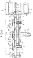
- FIG. 1 A first embodiment of the present invention will now be described as applied to a sequence of command and control signals for a robot manipulator device of a sheet metal bending press the structure of which is represented in Figures from 1 to 6; in particular, in Figure 1 there is illustrated a sheet metal bending installation 500, and the reference numeral 1 generally indicates a bending press including a die 2 and a die 3. In front of the press 1 there is a manipulator device generally indicated 4.
- a magazine On one side of the press 1 there is located a magazine with a loader device 5 and a discharge table generally indicated 6.
- An electronic microprocessor controlled unit 7 controls the operation of the manipulator device 4 and the press 1.
- the electronic unit 7 is provided with an alphanumeric keyboard 8, a video 9, and a small portable keyboard 11 (hand box) utilised in a manner which will be clarified hereinbelow.
- the loader device 5 comprises a bed 20 with an upper plane 22 on which rests a stack of flat, rectangular metal sheets 23 to be subjected to bending.
- a movable beam 24, controlled by actuators 26, carries a series of suckers 28 for lifting the sheets 23 in succession and transferring them to a horizontal position in the space between the loader device 5 and the discharge table 6, which latter is constituted by a simple bed with an inclined support plane 30.
- the plane 30 is intended, as will be seen, to receive the shaped sheets from the manipulator device 4.
- This manipulator device 4 includes a support base having feet 32 which carry a guide 34.
- the guide 34 extends parallel to the working plane of the press 1 along the whole of the lower part of the press 1, and into the space between the loader device 5 and the discharge table 6.
- an elongate carriage generally indicated 36 which is slidable parallel to the die 2, that is to say along the X-axis.
- the carriage 36 is movable along the guide 34 from a position in which it faces the press 1 to a position in which it is located between the loading device 5 and the discharge table 6.
- a servo motor 38 which is preferably numerically controlled.
- the servo motor 38 drives a toothed wheel (not shown) which cooperates with a rack (not shown) which extends along the guide 34.
- the carriage 36 supports, adjacent its ends, a pair of longitudinal guides 40 which extend parallel to the Y-axis. Each of these guides 40 is vertically slidable on the carriage 36 parallel to the Z-axis. Their movement along the Z-axis is controlled by a numerically controlled servo motor 42 carried by the carriage 36. Each guide 40 is supported by a vertical rod 44 slidable in the carriage 36. The servo motor 42 drives in unison respective toothed wheels (not shown) meshing with respective racks (not shown) supported by the rods 44.
- the guides 40 support a robust beam 46 which extends parallel to the bending zone defined by the dies 2 and 3.
- the beam 46 is supported on the guides 40 by respective slides 48 movable parallel to the Y-axis.
- Each slide 48 carries a vertical pin 50 about which the beam 46 can oscillate horizontally through a small angle.
- each slide 48 The movements of each slide 48 are controlled by a respective, numerically controlled servo motor 52 carried by the respective guide 40.
- Each servo motor 52 drives a respective worm screw (not shown) which extends within the guide 40 and which cooperates with a nut (not shown) fixed to the respective slide 48.
- the movements of the beam 46 along the Y-axis, during manipulation of the workpieces, are controlled by the two servo motors 52 acting in unison in such a way that the beam 46 moves parallel to itself.
- the press 1 is provided with a pair of alignment sensors 66 which are mounted on supports slidable along the Y-axis, and which are disposed close to the die 3.
- the sensors 66 are provided with a rod 67 which is movable parallel to the Y-axis and terminates with an end 68 adapted to detect contact with an edge of the metal sheet 23.
- the side of the beam 46 facing the press 1 carries two motor driven slides (not shown) slidable in unison and in opposite directions along the beam 46 itself; each slide carries a robust hollow projecting arm 74 extending towards the bending press 1. Each of these arms 74 carries at its free ends a respective manipulator head 10 the axis of rotation of which is common to the two heads.
- the movements of the two slides serve to cause engagement of the manipulator heads 10 with the edges of the sheet 23 and their disengagement therefrom.
- the rotations, in unison, of the two heads 10 about their axes, both for changing the attitude and the position of the manipulator pincers carried by the heads 10, are controlled by a numerically controlled servo motor.
- the head 10 comprises a square flange 90 which supports two projecting opposite cheeks 92 and 94.
- the free ends of these cheeks 92 and 94 are shaped in such a way as to constitute respective outer fixed jaws 96 and 98, of a manipulator pincer 72 and a manipulator pincer 73 respectively.
- a rod 100 Centrally between the two cheeks 92 and 94 extends a rod 100 to which is fixed a double piston.
- the piston is surrounded by a movable body 104 constituting a cylinder for the piston.
- the body 104 is movable to and fro along the rod 100.
- the disposition is such that when the pincer 73 is open the pincer 72 is closed and vice versa.
- the two diametrically opposite manipulator pincers 72 and 73 are situated eccentrically with respect to the axis of rotation of the head 10.
- the fixed jaws 96 and 98 are situated on the outline of the head, whilst the movable jaws 106 and 108 are slidable within the outline of the head 10. This disposition is the most favourable for achieving a manipulator head 10 of very small dimensions and permits the maximum possible approach of the manipulator pincers 72 and 73 to the bending zone.
- Both the fixed jaws 96 and 98 and the movable jaws 106 and 108 are replaceable in a simple and rapid manner with jaws of different dimensions, especially in width. Whilst the jaws 908 and 108 shown may be of minimum width, the maximum width of the jaws can be equal to the width of the head.
- auxiliary support device 110 For this purpose, along the beam 46 there is mounted at least one principal auxiliary support device generally indicated 110.
- This device 110 comprises a carriage 112 which is manually movable along the beam 46 and lockable on this in a desired position. If only one auxiliary device 110 is provided this position is the median position illustrated in Figure 1.
- a hollow projecting auxiliary support arm 114 is articulated on the carriage 112 about a horizontal axis parallel to the X-direction.
- an actuator (not shown) carried by the carriage 112 maintains the arm 14 in a raised position.
- the arm 114 carries an auxiliary support head 116 having two suction tubes.
- the head 116 is rotatable about an axis which coincides with the axis of rotation of the manipulator heads 10 and the auxiliary head 116 turns in unison with the manipulator heads 10.
- the head 116 carries two series of diagonally opposite lower suckers 119 and upper suckers 120 like the manipulator pincers 72 and 73 and having abutment surfaces which correspond with the gripping planes of the manipulator heads 10.
- the suckers 120 are connected, in a manner not shown, to a vacuum source (not shown).
- suckers 119 or 120 are able to support a sheet at its intermediate zone independently of the attitude of the surface of the sheet which they engage.
- the auxiliary support device 110 is utilised when forming the first bends.
- the actuator is controlled in such a way as to cause the arm 114 to descend to an inactive position.
- the auxiliary support 110 is flanked by two secondary support devices 121 which are disposed on opposite sides of the device 110 and have a similar structure.
- the devices 121 among other things have a plurality of upper suckers 123 and lower suckers 122 the function of which is analogous to that of the suckers 119 and 120.
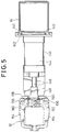
- a robust supporting column 124 is fixed to the floor on the side of the base 32 opposite that facing the press 1, which column includes two facing box-like uprights 125. Between the uprights 125 there is located a robust oscillating box-like arm 126 supported by the uprights 125 by means of a pin 128.
- a vertical actuator 130 ( Figure 2). Associated with the arm of the actuator 130 there is a pulley block 132 for a chain 134 anchored to the arm 126.
- the arm 126 carries a beam 14 which carries spaced pincers 12 at its front and is mounted so as to be rotatable through 180° at the free upper end of the oscillating arm 126.
- a double acting longitudinal pneumatic actuator 136 which controls the rotation of the beam 14 about the support axis on the arm 126 by means of a chain transmission 138.
- the structure comprising the arm 126, the beam 14 and the pincers 12 can be made to oscillate, by means of the actuator 130, between the inclined position illustrated in solid outline in Figure 2 and the vertical raised position illustrated in broken outline in Figure 2.
- FIG 2 the beam 46 and one of the support arms 74 of the manipulator heads 10 are shown in solid outline in the lowermost position of greatest advance towards the press 1, and in broken outline in the uppermost and most retracted position.
- the reference numeral 139 indicates the manipulation space within which the common axis of rotation of the manipulator head 10 and the auxiliary support head 116 can move.
- the beam 14 has a pair of longitudinal guides 140 along which are mounted four slides 142 which are manually displaceable and lockable on the guides themselves in the positions considered most convenient.
- each slide 142 has fixed to it the cylinder 144 of a double acting pneumatic actuator 146.
- the arm of the actuator 146 is indicated 148 and projects forwardly with respect to the beam 14.
- the cylinder 144 carries a bracket 150 which surrounds the arm 148 and carries a transverse pin 152.
- the pin 152 constitutes a central fulcrum for the two symmetrical jaws 154 of the auxiliary pincer 12.
- Each jaw 154 is provided with a pair of lateral rollers 156.
- the arm 148 is provided with a front plate 158 with which the rollers 156 cooperate.
- tension coil springs 160 hooked into respective cavities or seats of the plate and the jaw.
- the arrangement is such that when the actuator 146 and the plate 158 are retracted, the springs 160 maintain the pincer 12 open with the jaws 154 separated, as illustrated in solid outline in Figure 5.
- FIG 12 the interconnections between the electronic control unit 7 and the various devices connected to it and controlled by it are shown schematically.
- the electronic unit 7 controls the press 1, the manipulator device 4, the loader device 5, and the discharge table 6 (if automated with a device for removing the finished pieces from the plane 30).
- the electronic unit 7 is moreover provided with a portable keyboard 11 and a keyboard 8 utilised to create a sequence of control signals in a manner which will be explained clearly hereinbelow.
- the electronic unit 7 is finally provided with a video 9 for visualisation of the sequence of control signals, and can be connected to an external unit 480, indicated in broken outline, which can be utilised both for the generation and for the memorisation of sequences of control signals.
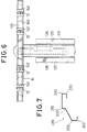
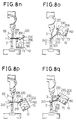
- FIG 7 there is shown the profile of a shaped workpiece 499 having six parallel bend lines 200, 210, 220, 230, 240 and 250 obtained from a flat metal sheet 23 of rectangular form by a bending cycle which will be described in detail with reference to Figures 8a to 8q.
- the bending press 1 is schematically illustrated as comprising the lower die 2 and the upper die 3.
- the die 2 is fixed, whilst the die 3 is reciprocably movable in a vertical working plane.
- the die 2 has a hollow profile with a dihedral angle and the die 3 has a complementary convex profile with a dihedral angle.
- the dihedral angle is 90° and is symmetrical with respect to the working plane.
- the manipulator device 4 comprises a pair of manipulator heads 10 which carry respective manipulator pincers 72 and 73.
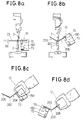
- These pincers 72 and 73 are illustrated in Figures 8a-8q in a different position from that illustrated in Figure 3; in particular the pincers 72 and 73 have gripper openings on the same side of the head 10 and are movable in unison and in opposition (closure and opening) with respect to one another.
- Each manipulator head 10 is mounted rotatably about an axis 150 common to the two heads.
- the heads 10 are caused to rise simultaneously until they carry the sheet 23 onto the die 2 with the rear edge of the sheet 23 coming into contact with the ends 68 of the sensors 66; in this way the sensors 66 emit a signal which indicates that the sheet 23 has reached, within the interior of the press 1, the predetermined position for the formation of the first bend 200 at the predetermined height.
- the die 2 and the die 3 are then caused to advance towards one another in such a way as to retain the sheet 23 without bending it.
- the following phase is the bending phase in which the die 3 is further lowered and forms the bend 200 in the sheet 23.
- the auxiliary pincers 12 lie in an inclined gripping plane. To permit the gripping of the sheet 23 by the auxiliary pincers 12, in their rising motion moving away from the press 1 the heads 10 have been caused to rotate in such a way as to carry the leaf 206 of the sheet 23 into correspondence with this plane. As illustrated in Figure 8c, the auxiliary pincers 12 grip the longitudinal edge of the sheet 23.
- the manipulator pincers 72 disengage from the lateral edges of the sheet 23 and move away.
- the two heads 10 are again lowered, turning about the axis 150, and advanced to bring the leaf 206 of the sheet 23 to rest on the edges of the die 2.
- the sheet 23 is rested on the die 2 in such a way that the rear edges of the leaf 206 are aligned with the ends 68 of the sensors 66 positioned along the Y axis at a height corresponding to the production of the second bend 210.
- the head 10 performs a rotation about its axis 150 and translates gripping the sheet 23 by means of the pincers 72 ( Figure 8h).
- the press 1 is opened again and the leaf 206 of the sheet 23 is inserted between the die 2 and the die 3 until the rear edge comes into contact with the sensors 66 as illustrated in Figure 8i, for the production of the fourth bend 230. Subsequently the sheet 23 is released from the pincers 72 and the press 1 forms the fourth bend 230. As can be established from Figure 8j, after the production of the fourth bend a part of the leaf 206 of the sheet 23 envelops the die 3. This prevents or renders difficult the disengagement of the sheet 23 from the die 3 during its rising movement.
- the two heads 10 gripping the sheet 23 with the pincers 72 are therefore raised and simultaneously rotated about their axis of rotation 150 during the elevation of the die 3 so as to release the sheet 23 from the die 3 (tracking).
- the auxiliary pincers 12 grip the edge of the leaf 205 of the sheet 23 ( Figure 8l) along its longitudinal edge, and the manipulator pincers 72 disengage from the lateral edges of the leaf 206; subsequently ( Figure 8m) the auxiliary pincers 12 invert the sheet 23 by rotation of the beam 14, then the manipulator pincers 72 grip the leaf 205 of the sheet 23 again, and finally the auxiliary pincers 12 open and move away.
- manipulator pincers 72 release the sheet 23 retained between the die 2 and the die 3, and the die 3 descends to the position corresponding to Figure 8o, and forms the fifth bend 240.
- the press 1 is then re-opened and the manipulator device 4 moves to the discharge table 6 where the pincers 72 release the workpiece 499 which falls onto the plane 30 of the table 6.
- the electronic unit 7 is in fact provided with a programme by which it is possible, by means of the portable keyboard 11 (hand box), or possible by means of the keyboard 8, to define a complete sequence of operating phases which can be performed by the sheet metal bending installation 500.
- the keyboard 11 is provided with a plurality of function keys 260 each of which is adapted to define a complete sequence of command and control signals for the sheet metal bending installation 500, for a respective phase in the cycle by which a shaped sheet metal profile is formed, for example of the type illustrated in Figure 7.
- These sequences of control and command signals, corresponding to each of the function keys 260, are conveniently memorised in a memory block of the electronic unit 7.
- the keys 260 are indicated with a letter “F” to define that this key is a function key, and with a number, indicated after the letter "F", to distinguish the various operating functions which can be achieved by means of the keys 260.
- the keyboard 11 (hand box), is also provided with other keys which can also be used in combination with the function keys 260 to define other instructions which can be executed by the sheet metal bending installation 500.
- the keyboard 11 includes a key 261 indicated with the symbol "MOVE” adapted to define command signal instructions for translation of the manipulator device 4 along three axes X, Y and Z.
- the "MOVE" key 261 is also able to define instructions for signals commanding rotation of the heads 10 about their common axis 150, displacement of the head 10 along the axis X, and finally rotation of the beam 14 and inclination of the arm 126.
- the "MOVE" key 261 is utilised jointly with other keys on the keyboard 11 to define a vector which comprises all the movements listed above and definable by the "MOVE" key itself.
- the (hand box) keyboard 11 includes:
- This vector can be of the form: MOVE ( ⁇ X, ⁇ Y, ⁇ Z, ⁇ A, ⁇ B, ⁇ C, ⁇ D)
- MOVE is the instruction defined by the key 261 and X, Y, Z, A, B, C and D are the numerical values inserted by means of the keys 262-268 which represent how far and in which direction the beam 46 of the manipulator 4, the heads 10, the beam 14, and the arm 126 must move with respect to an initial position.
- the key 261 can be utilised successively to create a sequence of vectors of the type: MOVE ( ⁇ X 1 , ⁇ Y 1 , ⁇ Z 1 , ⁇ A 1 , ⁇ B 1 , ⁇ C 1 , ⁇ D 1 ) MOVE ( ⁇ X 2 , ⁇ Y 2 , ⁇ Z 2 , ⁇ A 2 , ⁇ B 2 , ⁇ C 2 , ⁇ D 2 ) MOVE ( .................-2018) MOVE ( ⁇ X n , ⁇ Y n , ⁇ Z n , ⁇ A n , ⁇ B n , ⁇ C n , ⁇ D n )
- the keyboard 11 further includes a "MEM" key 269 for memorisation of the previously made key selections, and the manner of operation of this will be described in more detail below.
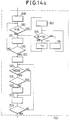
- Figure 9 is a flow chart illustrating the operations performed by the electronic command unit 7 to create the basic sequence of command and control signals for the bending installation 500 so as to be able then to perform the bending cycle previously described to produce the profile illustrated in Figure 7.
- the initial block 270 detects if the creation of a new sequence of operating phases has been requested by the operator, for example with the selection on the keyboard 8 or 11, or if the execution of previously memorised operating phases has been requested.
- the system passes from block 270 to block 272 which detects if a key of the keyboard 11 (hand box) has been pressed. In the negative case it remains in closed cycle in this block waiting for a key to be pressed. If a key has already been pressed, from block 2727 the system passes to a block 273 which detects if a function key 260 has been pressed. In the positive case, from the block 273 it passes to a block 274 which commands execution of the phases determined by the function key 260 which has been pressed. From block 274 it passes to a block 275 which detects if the memorisation of the selected function key has been requested by means of the key 269.
- this block detects that a function key 260 has not been pressed it passes to a block 277 which detects if the key pressed is the key 261 defining a sequence of movements. If a key has been pressed which is not a key defining a sequence of movements, it moves from block 277 onto a block 278 which commands execution of the operation requested with this key, and subsequent exit from the programme. If the block 277 detects that the key 261 defining an instruction for movement has been pressed, it passes to a block 279 which commands execution of the movement requested by means of the keys 262-268. From block 279 it then moves to a block 280 which detects if memorisation of the selected movements has been requested by means of the key 269.
- Figures 10a and 10b are a flow chart illustrating its operation of the electronic unit 7 with the system of Figure 9, and define the sequence of command and control signals for the bending installation 500 to perform the bending cycle previously described with reference to Figures 8a-8q to obtain the workpiece 499 of Figure 7.
- This arrangement therefore has a sequence of blocks which comprise instructions for movement of the parts of the installation (heads 10, press 1, loader device 5 etc) or instructions for the operation of the installation (defined by the said function keys 260).
- the process starts initially at a block 300 which initiates the general starting procedures of the programme. From block 300 it passes to a block 301 which comprises the instructions for the signals to command the loader device 5 to take up the sheet 23 and for the lateral positioning of the bed 20 over the sliding zone of the beam 46 on the guide 34; these instructions are determined by activation of the function key 260 indicated F22 on the keyboard 11.
- a block 304 which comprises, with a previously defined "MOVE" vector, the sequence of instructions created by activation of the key 261 and keys 262 for the coarse movement signals defining the movement of the manipulator device 4 towards the bed 20 for loading the sheet 23.
- a block 307 which comprises the instructions, created by activation of the key 261 and keys 262, 263, 264, 265, 266 for the final and precise movement of the beam 46 and the gripper heads 10 of the manipulator device 4 so as to carry it and the pincers 72 into the gripping position at the edges of the sheet 23; from this block 307 it moves on to a block 308, defined by the function key F2, which comprises the instructions for the signals for commanding closure of the pincers 72 to grip the sheet 23.
- a block 310 defined by the function key F23 which comprises the instructions for separating the loader device 5 from the sheet 23 by means of disactivation of the suction from the suckers 28.
- a block 311 comprising, with the MOVE vector, the instructions for movement of the beam 46 of the manipulator 4 towards the press 1 (carrying the sheet 23); this block 311 is followed by a block 470, defined by the function key F21 which comprises the instructions for command signals for the sensor positioning procedure (sensors 66) which define the depth of alignment of the sheet 23 into the press 1 ( Figure 8a).
- the block 470 is followed by a block 471 which comprises the instructions for the command signals for moving the heads 10 and the beam 46 of the manipulator device 4 to bring the rear edge of the sheet 23 up to the sensors 66. From block 471 it passes to a block 312, defined by the function key F17, which comprises the instructions for signals commanding the procedure for alignment of the sheet 23 in the press 1, in the position for forming the first bend 200, and lowering of the die 3 into contact with the sheet 23 to retain it in position.
- the block 312 is followed by a block 313, defined by function key F1, which comprises the instructions for the command signals for opening the pincers 72.
- a block 314 which comprises the instructions for command signals for withdrawing the manipulator heads 10 from the manipulation space 139.
- block 316 From block 316 it passes to a block 317 which comprises the instructions for the command signals for movement of the manipulator head 10 towards the bent sheet 23.
- a block 319 which comprises the instructions for command signals for the final and precise movement of the manipulator device 4 in such a way that the manipulator heads 10 arrive at a position such as to grip the folded sheet 23 ( Figure 8b). Subsequently it passes from block 319 to a block 320, defined by function key F2, comprising the instructions for command signals for closure of the pincers 72 to grip the sheet 23.
- the block 324 is followed by a block 325, defined by function key F1, which comprises the instructions for the command signals for opening the pincers 72 to release the sheet 23.
- a block 326 which comprises the sequence of instructions for command signals to withdraw the device 4 from the manipulation space 139.
- the block 327 is followed by a block 330 defined by function key F3, which comprises the instructions for opening the pincers 73.
- the block 334 is followed by a block 335, defined by function key F21, which comprises the instructions for the signals to command the procedure for positioning the sensors 66 ( Figure 8e).
- the block 335 is followed by a block 336 which comprises the instructions for the command signals for movement of the heads 10 and the beam 46 of the manipulator device 4 to cause the rear edge of the sheet 23 to approach the sensors 66.
- block 336 From block 336 it passes to a block 337 defined by function key F17, which comprises the instructions for command signals for the procedure for alignment of the sheet 23 in the press 1, and gripping it between the dies 2 and 3.
- function key F17 which comprises the instructions for command signals for the procedure for alignment of the sheet 23 in the press 1, and gripping it between the dies 2 and 3.
- the block 337 is followed by a block 338, defined by function key F3, which comprises the instructions for signals commanding opening of the pincers 73.
- block 340 which comprises the instructions for command signals for withdrawal of the heads 10 of the device 4 from the bending zone.
- block 342 which comprises the instructions for the command signals for movement of the heads 10 of the manipulator device 4 towards the sheet 23, which now has the two bends 200 and 210.
- the block 342 is followed by a block 343 which comprises the instructions for signals commanding the final and precise movement of the manipulator device 4 in such a way that the pincers 73 of the manipulator head 10 are moved to a position adapted to grip the leaf 205 of the bent sheet 23.
- block 346 From block 346 it passes to a block 347 which comprises the instructions for command signals for controlling movement of the manipulator heads 10, for repositioning the metal sheet 23 in the press 1.
- the block 347 is followed by a block 350, defined by function key F21, which comprises the instructions for command signals for controlling the procedure for repositioning the sensors 66, for achieving the third bend 220 ( Figure 8g).
- the block 350 is followed by a block 351 which comprises the instructions for signals commanding the movement of the head and the beam 46 of the manipulator device 4 to bring the rear edge of the sheet 23 up to the sensors 66.
- the block 351 is followed by a block 353, defined by the function key F3, which comprises the instructions for signals commanding opening of the pincers 73.
- block 354 which comprises the instructions for signals commanding disengagement of the heads 10 of the device 4 from the bending zone.
- the block 355 is followed by a block 356 defined by the function key F1, which comprises the instructions for the signals commanding opening of the pincers 72 to prepare them for the subsequent gripping of the sheet 23.
- block 357 which comprises the instructions for signals commanding movement of the heads 10 of the manipulator device 4 towards the sheet 23, which now has three bends 200, 210, 220.
- the block 357 is followed by a block 359 which comprises the instructions for the command signals for the final and precise movement of the manipulator device 4 in such a way that the pincers 72 of the manipulator heads 10 are moved into a position adapted to grip the leaf 205 of the bent sheet 23.
- a block 365 which comprises the instructions for command signals for the movement of the manipulator heads 10, for repositioning the leaf 206 of the metal sheet 23 in the press 1.
- the block 365 is followed by a block 366, defined by function key F21, which comprises the instructions for command signals for the procedure for repositioning the sensors 66 for forming the fourth bend ( Figure 8i).
- the block 366 is followed by a block 367, defined by the function F17, which comprises the signals for commanding the procedure for alignment of the sheet 23 in the press, and gripping it between the dies 2 and 3.
- the block 367 is followed by a block 368, defined by the function key F1, which comprises the instructions for the signals for commanding opening of the pincers 72.
- From block 368 is passes to a block 370 which comprises the instructions for command signals for withdrawal of the heads 10 of the device 4 from the bending zone.
- block 373 which comprises the instructions for the command signals for movement of the heads 10 of the manipulator device 4 towards the sheet 23, which now has four bends 200, 210, 220 and 230.
- the block 373 is followed by a block 375 which comprises the instructions for command signals for the final and precise movement of the manipulator device 4 in such a way that the pincers 72 of the manipulator heads 10 are disposed in a position suitable for gripping the leaf 206 of the bent sheet 23.
- block 382 which comprises the instructions for command signals for withdrawal of the device 4 from the manipulation space 139.
- the block 450 is followed by a block 451, defined by function key F14, which comprises the instructions for the command signals for opening the auxiliary pincers 12.
- a block 452 which comprises the instructions for the command signals for movement of the head 10 towards the press 1.
- the block 452 is followed by a block 386, defined by function key F21, which comprises the instructions for signals commanding the procedure for a new positioning of the sensors 66 ( Figure 8n).
- the block 386 is followed by a block 387, defined by the function key F17, which comprises the instructions for signals commanding the procedure for alignment of the sheet 23 in the press 1 and gripping it between the dies 2 and 3.
- the block 387 is followed by a block 388, defined by the function key F1, which comprises the instructions for signals commanding opening of the pincers 72.
- block 390 which comprises the instructions for signals commanding withdrawal of the heads 10 of the device 4 from the bending zone.
- the block 391 is followed by a block 460 which comprises the instructions for command signals for movement of the heads 10 of the manipulator 4 towards the sheet 23 which now has five bends 200, 210, 220, 230 and 240.
- the block 460 is followed by a block 392 which comprises the instructions for signals commanding the final and precise movement of the manipulator device 4 in such a way that the pincers 72 of the manipulator heads 10 are disposed in a position adapted to grip the leaf 206 of the bent sheet 23.
- the block 461 is followed by a block 394 which comprises the instructions for signals commanding the movement of the manipulator heads 10, and the repositioning of the metal sheet 23 in the press 1 ( Figure 8p).
- block 394 From block 394 it passes to block 395, defined by function key F21, which comprises the instructions for signals commanding the procedure for the new positioning of the sensors 66.
- the block 395 is followed by a block 396, defined by the function key F17, which comprises the instructions for the signals commanding the procedure for aligning the sheet 23 in the press 1, and gripping it between the dies 2 and 3.
- the block 396 is followed by a block 397, defined by the function key F1, which comprises the instructions for signals commanding the opening of the pincers 72.
- block 400 which comprises the instructions for the signals commanding withdrawal of the heads 10 of the device 4 from the bending zone.
- a block 402 which comprises the instructions for the command signals for movement of the heads 10 of the manipulator device 4 towards the finished workpiece 499.
- the block 402 is followed by a block 404 which comprises the instructions for the command signals for final and precise movement of the manipulator device 4 in such a way that the manipulator heads 10 are disposed in a position adapted to grip the bent workpiece 499.
- a block 410 which comprises the instructions for command signals for the movement of the manipulator device 4 to the position for transforming the workpiece 499 to the discharge table 6.
- the block 410 is followed by a block 411, which comprises the instructions for command signals for the final and precise movement of the manipulator device 4 in such a way that one side of the workpiece 499 rests on the inclined support plane 30 of the discharge table 6.
- the sequence of command signals is treated by the electronic unit 7, with the system constituting the subject of the present invention, which provides for increasing the working speed of the sequence itself.
- the electronic unit 7 comprises, as illustrated in Figure 13, a first block 501 which checks if a sequence of command and control signals for the manipulator device 4 and the system 500 already exists; if this sequence does not exist it exits from the programme, on the other hand if this sequence does exist it passes to a second block 502 which effects a first increase in the speed of the sequence.
- the block 502 acts on the instructions for displacement command signals for the manipulator device 4, defined conveniently with the "MOVE” key, and initially checks if the "MOVE” type instructions are isolated, or if they are grouped in a sequence. If the "MOVE” instructions are isolated they are not modified. If instead these "MOVE" type instructions are grouped in a set of two or move consecutive instructions the block 502 associates each instruction of the group with the following one.
- the block 502 associates together the pairs of numerical values X, Y, Z, A, B, C, D of two consecutive "MOVE" instructions (which correspond to the position assumed by the heads 10 and the arm 126 with the beam 14 in a first and in a second position) in such a way as to approximate the trajectory passing through the said positions, and therefore to reduce the time taken for the displacement.
- This association operation is repeated for all the pairs of successive "MOVE" instructions in such a way that a movement of the heads 10 which has been defined by means of a complex trajectory constituting the sum of individual trajectories between a number of positions, is speeded up in that each individual trajectory is modified and recorded with the adjacent trajectories; it is therefore not necessary to have to stop in the intermediate positions, but only to stop in the final position, defined by the last "MOVE" instruction of the group, which has not been modified.
- the block 502 further determines, before the said association between the "MOVE” instructions, a testing of the successive "MOVE” instructions at each bending phase of the press 1, and generates, before the sheet 23 is taken again by the heads 10, a synchronisation and control signal obtained after the bend execution command so as to allow the correct completion of the bending phase and subsequent secure gripping by the heads 10 without having to wait for completion of the bending phase before initiating the movement of the heads 10 towards the sheet 23.
- a positive condition detected by the block 510 it moves on to a block 560 which associates, to the block for commanding execution of a bend, conveniently defined by the function key F18, the commencement of a parallel sequence for obtaining this synchronisation and control signal T3, and then moves onto a block 515 which detects if the instruction under examination commands the final and precise positioning of the pincers 72 or 73 of the heads 10 at the sides of the sheet 23, which is detectable for example by means of the value of the dimension B of the "MOVE" instruction by referring it to the positioning of the heads 10 along the X-axis with respect to a central reference point on the beam 46, and testing if this value B is less than a value B1; if not this indicates that the instruction under examination still relates to a displacement before this final and precise positioning of the pincers 72 or 73 of the heads 10 against the edges of the sheet 23 so that it moves on to a block 516 which commands analysis of a subsequent instruction of the flow chart of Figure 10a and 10b,
- Block 517 there is therefore introduced a block 517' to command the delay in the signal T3, between the blocks 317 and 319 of Figure 10a, as can be seen in the final block diagram obtained according to the present invention and illustrated in Figures 15a and 15b, and similarly blocks 517' are inserted between the other pairs of corresponding blocks 342-344, 357-359, 373-375, 460-392, 402-404.
- the block 560 links the commencement of the sequence to obtain the signal T3 to each of the blocks 315, 341, 355, 371, 391 and 401 for commanding the formation of a bend.
- the block 513 then in turn commands analysis of the first instruction of the flow chart illustrated in Figures 10a, 10b then moves on to a block 520 which detects if this instruction is of the "MOVE" type, and if so moves on to a block 521 which detects if this instruction is isolated, that is to say relates to a displacement between two individual points: if not it moves on to a block 522 which associates this "MOVE" instruction to the subsequent "MOVE" instruction as already indicated, and then moves on to a block 523 which commands the analysis of a subsequent instruction of this block diagram of Figures 10a and 10b. It also moves directly to this block 523 following detection of the negative condition of the block 520 or the positive condition of the block 521. From block 523 it moves to block 524 which detects if this instruction is the last one of the cycle. If it is not it returns to block 520, whilst if it is it exits from block 502.
- the block 503 modifies and optimises the sequences of command signals relating to the movement of the manipulator device 4 and the loader device 5, in such a way that when the manipulator device 4 is positioned to release the finished workpiece 499 on the discharge table 6 the initiation of the new phase of loading a metal sheet 23 from the magazine 5 is commanded and, moreover, before the gripping of the new sheet 23 with the heads 10 there is a delay in the synchronisation and control signal T2 following the command for the sheet 23 to be lifted by the loading device 5 so as to allow the correct positioning of the sheet 23 over the beam 46 by the loading device 5.
- a first block 529 which commands analysis of the first instruction of the flow chart illustrated in Figures 10a and 10b, which then moves on to a block 530 which detects if this instruction relates to the command to form a final bend in the sheet 23, defined by the function key F18; in the negative case it moves on to a block 531 which commands analysis of a subsequent instruction of this block diagram of Figures 10a and 10b, and then returns to block 530, whilst in the positive case it moves on to a subsequent block 532 which detects if the instruction under examination commands the final and precise positioning of the manipulator device 4 in such a way that the workpiece 499 is lowered on to the inclined plane 30 of the discharge table 6, detectable for example by means of the value of the dimension Z of the move instruction referring to the positioning of the height of the heads 10, and checking if this value Z is greater than a value Z1; in the negative case this indicates that the instruction under examination still relates to a displacement preceding this final
- block 535 determines the delay in the signal T2 before the final and precise movement of the beam 46 and the gripper heads 10 of the manipulator device 4 to the grip position to grip the sides of the sheet 23, which is defined by the block 307 of Figure 10a.
- this block 535 there is therefore inserted a block 535' for commanding a dealy in the signal T2, after the block 412 and before a block 307, as can be seen in the final flow chart according to the present invention and illustrated in Figure 15b; this block 307 is then followed by a block 308 and thereafter, as illustrated in Figure 10a, by a new bending cycle.
- From block 535 it exits from block 503, and from block 503 ( Figure 13) it exits from the system of the present invention for increasing the speed of operation of the sequence of command and control signals for the bending installation 500.
- the arrangement of the second embodiment differs from that of the first embodiment in the arrangement shown in Figs. 16a, 16b-22.
- a sequence of command signals of the type described above, and defined for a given bending installation is modified automatically by the electronic unit 7 on the basis of the dimension of the bending installation on which it effectively operates.
- a sequence of command signals for example those utilised to form the profile illustrated in Figure 7, is created by controlling a bending installation having a given configuration utilised as a reference for all the other bending installations; this specimen bending installation will be indicated hereinafter with the term "master” and all the other similar bending installations assembled subsequently will be indicated with the term "slave”.
- the second embodiment of the present invention operates to perform a series of tests on the "master” installation and on the "slave” installation, to detect by how much certain dimensions of the configurations comprising parts of the "slave” installation differ from the corresponding dimensions of the "master” installation, and to modify the sequence of command signals utilised on the "slave” installation (but defined for the "master” installation) in such a way that this sequence of command signals controls the "slave” bending installation in an absolutely correct and precise manner.
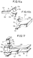
- a first and a second metal specimen block are utilised, illustrated in Figures 16a and 16b, and indicated with the numerals 702 and 707, which are respectively gripped by the auxiliary pincers 12 and by the pincers 72 and 73 of the heads 10, and serve as abutment elements for the detection of various dimensions of these installations, as will be described hereinbelow.
- the first specimen block 702 includes a first flat portion 703 shaped as a rectangular parallelepiped from one end of which extend two portions 704 of greater thickness, which terminate with flat front surfaces 705. These appendices 704, moreover, are inclined with respect to the portion 703 by an angle gamma ( ⁇ ) equal to about 130° so as to be divergent from one another.
- ⁇ angle gamma
- the second specimen block 707 comprises a flat parallelepiped main portion 708 from the front of which extends a coplanar projection 709 of reduced thickness which terminates with a flat front surface 710.
- the portion 708 has a second portion 711, which extends laterally of the portion 708 in a direction perpendicular to the first projection 711, and terminates with a flat front face 712 which functions as an abutment element in a manner which will be clarified hereinbelow, moreover this portion 711 has an end part 714 of greater thickness at the top, the surface of which will also be utilised as will be seen in detail.
- the blocks 702 and 707 are firmly gripped, respectively, by an auxiliary pincer 12 of the auxiliary support group 124, and by a pincer 72 of the manipulator heads 10; in particular, the jaws 154 of the pincer 12 close on the free end faces of the flat portion 703 of the block 702, and the jaws 96 and 106 of the pincer 72 close on the faces of the main portion 708 of the block 707.
- auxiliary support group 124 and the manipulator device 4 are then moved, conveniently by means of the keyboard 11 and the associated movement keys as described hereinabove, in such a way that the box-like arm 126 is tilted down towards the press 1, and consequently the beam 14, which carries the auxiliary pincers 12 is likewise lowered so that the axis of the upper portion 704 of the block 702 is located horizontally; the manipulator head 10 which carries the block 707 is in turn displaced until it approaches the block 702, and the flat front face 712 of the block 707 comes into contact with the side wall of the portion 704 with the upper front edge of the end wall 714 fitting together with the upper side edge of the portion 704.
- an operator imparts to the loader device 5 the instruction to load a sheet 23 so that the suckers 28 grip this sheet 23 which is then raised by the beam 24, and positioned between the loader device 5 and the discharge table 6 in the gripping zone of the heads 10.
- the operator for example still by means of the keys on the keyboard 11, causes the beam 46 to move along the X axis towards the magazine 5, and causes the head 10 carrying the block 707 to move, as has already been described in the first detection configuration, until the upper front edge of the end wall 714 of the block 707 comes into contact with the lateral edge of the sheet 23 (which is rectangular) parallel to the Y axis ( Figure 18a) with the central axis of the upper wall of this part 714, coincident with the central axis of the sheet 23 (along the X axis).
- This second detection configuration can also be effected with a pair of blocks 707 carried by the pair of heads 10 against the parallel lateral edges of the sheet 23 ( Figure 18b).
- the dimensions X, Y, Z, A, B of this second configuration and which identify the position of the sheet 23, and consequently of the supporting loading device 5, with respect to the manipulator device 4, are also memorised as will be described below.
- an operator again conveniently utilising the keyboard 11, moves the beam 46 until the heads 10 are located in front of the discharge table 6. Subsequently the heads 10 which carry a respective block 707 as already illustrated for the preceding detection configurations, are raised and caused to rotate in such a way that the block 707 is located in front of the support bed 30 with the projection 709 facing towards this bed 30 and positioned on parallel inclined planes.
- Figure 20 there is illustrated in detail a flow chart of a first operating stage of the system according to the present invention, conveniently effected with a command and control unit 7 of the specimen installation, in which the dimensions (X, Y, Z, A, B, C, D) relating to the predetermined detection configurations and described hereinabove with reference to Figures from 14 to 16 are memorised for this "master" specimen bending installation 500.
- this block 731 can preliminarily present on the video 9 a schematic illustration such as that shown in Figure 17, which serves as a guide for the operator for the configuration which must be achieved.
- a block 732 analogous to block 731 it passes to a block 732 analogous to block 731 which, after the second predetermined detection configuration has been reached ( Figure 18a) conveniently preliminarily shown on the video 9, commands the acquisition of the second set of dimensions which define the position of the loader device 5 with respect to the manipulator device 4 of the master installation.
- the block 733 is followed by a block 736 which provides for regrouping of the said first, second and third sets of dimensions in a form which can be extracted from the electronic unit 7.
- FIG 21 there is illustrated in detail a flow chart of a second operating stage of the system of the present invention, conveniently put into effect with the command and control unit 7 of the slave installation to be tested, in which the dimensions (X, Y, Z, A, B, C, D) relating to the three predetermined detection configurations described hereinabove with reference to Figures from 17 to 19 are detected in this "slave" installation and memorised. These dimensions are then compared with the previously detected corresponding dimensions of the "master” installation, and there is then performed, in an automatic manner, an adaptation of the sequence memorised in a sample installation of the command and control signals defining a bending cycle for the said installation.
- the dimensions X, Y, Z, A, B, C, D
- first block 740 which tests if the three sets of "master” installation dimensions for the three configurations defined hereinabove have been already memorised in the electronic unit 7 of the assembled “slave” installation 500. In the negative case it exits from this stage, whilst in the positive case it passes from block 740 to a block 731', analogous to the block 731 of Figure 20, which, after the first predetermined detection configuration has been reached by the "slave” installation ( Figure 17) commands, by means of a key of the keyboard 11 selected by an operator, efffects the acquisition in a memory block of the unit 7 of the "slave” installation 500, of a first set of dimensions which define the position of the auxiliary support unit with respect to the manipulator device 4.
- this block 731' can also preliminarily present to the operator, on the video 9, a schematic illustration of the detection configuration which must be reached.
- a block 732' analogous to the block 732 of Figure 20, which after the second predetermined detection configuration has been reached by the slave installation ( Figure 18a) commands the acquisition of the second set of dimensions which define the position of the loader device 5 with respect to the manipulator device 4 of the slave installation.
- the block 733' is followed by a block 746 which provides for monitoring the compatibility of the dimensions of the "master” installation with those of the "slave” installation indicative of the correct assembly of the "slave” installation.
- This block 746 tests by how much the dimensions of the "master” in each of the three detected configurations differ from the corresponding dimensions of the "slave” installation, and if this difference exceeds predetermined limit values previously defined and memorised in the electronic unit 7 the block 746 provides a display on the video 9 of the dimensions exceeding the normal, and activates an acoustic alarm signal so that the operator can arrange for rectification of the assembly of the bending installation 500.
- the block 747 determines the end of the dimensional testing stage according to the present invention, whilst on the other hand if all these differences are less than the limit values it passes to a block 748 which acts to effect automatic correction of a memorised sequence defined on a specimen system for the command and control signals defining a bending cycle to be performed on the "slave" installation 500.
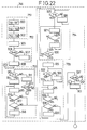
- the block 748 of Figure 21 is illustrated in detail in Figure 21. It starts with a block 751 which recalls from the memory of the electronic unit 7 the corresponding dimensions for the three predetermined detection configurations of the "master” and “slave” installations, compares them and finally calculates the associated differences; in particular a first block 900 calculates the differences X1, Y1, Z1, A1, B1, C1, D1 between the dimensions X, Y, Z, A, B, C memorised by the blocks 731 and 731' in the first detection configuration, a second block 901 calculates the differences X2, Y2, Z2, A2, B2, C2, D2 between the dimensions X, Y, A, B, C, D memorised by the blocks 732 and 732' in the second detection configuration, and a third block 902 calculates the differences X3, Y3, Z3, A3, B3, C3, D3 between the dimensions X, Y, Z, A, B, C, D memorised by the blocks 733 and 733' in the third detection configuration.
- a block 752 which re-examines the created sequence of command signals (for example of the type described with reference to Figures 10a and 10b) and searches within this sequence of instructions for command signals produced with the MOVE key and thus expressed in the form MOVE ( ⁇ X, ⁇ Y, ⁇ Z, ⁇ A, +B, +C, +D), and relating to the displacement of the manipulator device 4 in proximity to the loading device 5;
- the block 752 thus modifies all the signals expressed with the MOVE key in which the variable X is greater than a predetermined numerical reference value X 0 (for example X ⁇ 3500), which indicates that the manipulator device 4 is located close to the loading device 5, and this block 722 modifies the values of these movement command instructions on the basis of the differences X2, Y2, Z2, A2, B2, C2 determined by the block 901 and representative of the differences between the dimensions of the "master” and "slave” installations for the movement instructions relating to this loading stage.
- a first block 905 which commands the analysis of the first instruction of the flow chart illustrated in Figures 10a and 10b and formed as described, then moves on to a block 906 which detects if this instruction relates to the command for positioning the heads 10 against the sheet 23, carried by the loading device 5, which is detectable by means of the value of the dimension X of the "MOVE" instruction, i.e. by testing if this value X is greater than a value X 0 .
- the block 753 searches in the previously memorised sequence of command signals those command signals indicative of a commencement of utilisation of the auxiliary support group 124 and obtained for example by means of the function key F13. Once this command signal is found the Y and Z values of the "MOVE" type command signal which immediately precedes the command signal formed utilising the function key F13 are memorised.
- block 910 which tests if the instruction of the flow chart of Figures 10a and 10b under examination relate to the command for initiation of the use of the auxiliary support group 124 (determined by the function key F13); in the negative case it moves on to block 911 which commands analysis of a subsequent instruction of this flow chart of Figures 10a and 10b, and then moves on to a block 912 which, in an analogous manner to block 906, detects if this instruction relates to the command for positioning the heads 10 with the sheet 23 at the discharge table 6, this being detectable by means of the value of the dimension X of the "MOVE" instruction, and testing if this value X is greater than a value X 0 ; in the negative case this indicates that the instruction under examination still relates to an earlier stage or displacement than this final positioning of the heads 10 with the sheet 23 at the discharge table 6 so that it returns to the block 910, whilst in the positive case it moves on to a block 913 the operation of which will be described in detail hereinbe
- a block 914 which commands memorisation of the Y and Z values of the "MOVE" type command signal which immediately precede the command signal relating to the block 910.
- a block 915 which commands analysis of a previous instruction defined in this flow chart of Figures 10a and 10b, and then to a block 916 which detects if this previous instruction is of the "MOVE" type and in the negative case it exits from block 753 and moves on to a subsequent block 754.
- a positive condition detected by the block 916 it moves on to a block 917 which detects if this movement instruction under examination has Y and Z values which differ from the Y and Z values memorised by the block 914 by an amount less than a respective predetermined maximum limit Y 0 and Z 0 : in the negative case (movement beyond this predetermined field) it exits from block 753 and moves to a subsequent block 754, whilst in the positive case it moves on to a block 918 which imposes on the instructions under examination, for each dimension of the command signal (X; Y; Z; A; B) a modification by a corresponding value X1; Y1; Z1; A1; B1; C1; D1 determined by the block 900, and then returns to the block 915 for continuation of the possible modification of all the preceding succession of movement instructions.
- the block 754 searches in the sequence of previously memorised command signals for command signals indicative of the termination of the utilisation of the auxiliary support group 124, and obtained for example by means of the function key F14. Once this command signal is found the dimensions of all the "MOVE" type command signals which lie between the beginning and the end of this use of the auxiliary support group 124 are changed, and these values of the command signals (X, Y, Z, A, B, C, D) are modified on the basis of the corresponding differences X1, Y1, Z1, A1, B1, C1, D1 determined by the block 900 and representative of the differences between the "master” and “slave” installations for the working stages as already described.
- block 554 has a block 925 which tests if the instruction of the flow chart of Figures 10a and 10b under examination relates to the command for the end of the use of the auxiliary support group 124 (determined by the function key F14); in the negative case it moves on to a block 926 which commands the analysis of a subsequent instruction in this flow chart of Figures 10a and 10b, and then returns to the block 925.
- a block 930 which detects if the instruction of the flow chart of Figures 10a and 10b under examination relate to the command to commence utilisation of the auxiliary support unit 124 (determined by the function key F13); in the negative case it returns to the block 927 which commands the analysis of a preceding instruction in the flow chart of Figures 10a and 10b, whilst in the case of a positive condition detected by the block 930, and thus indicative that the modification has been made for all the movement instructions lying in the field of use of the auxiliary support group 124, it exits from block 754 and moves on to a block 755 which, splitting off from the command signal indicative of the end of utilisation of the auxiliary support group 124, defined for example by the function key F14, commands the memorisation of the Y and Z values of the "MOVE" type command signal which immediately follows this command signal formed utilising the function key F14.
- block 755 has a block 931 which commands the analysis of a subsequent instruction of the flow chart of Figures 10a and 10b, and then moves on to a block 932, which, in a manner analogous to the block 925, tests if the instruction under examination of the flow chart of Figures 10a and 10b relate to the command for the end of utilisation of the auxiliary support group 124 (determined by the function key F14); in the negative case it moves on to a block 933, analogous to block 926, which commands analysis of a subsequent instruction of the flow chart of Figures 10a and 10b, and then returns to the block 932.
- a positive condition detected by the block 932 that is to say indicative of the command for the end of the use of the auxiliary support group 124, it moves on to a block 934 which commands the memorisation of the Y and Z values of the "MOVE" type command signal which immediately follows the command signal detected by the block 932. From block 934 it moves to a block 935 which commands the analysis of a following instruction defined in the flow chart of Figures 10a and 10b, and then to a block 936 which detects if this following instruction is of the "MOVE" type, and in the negative case it exits from block 755 and moves to a subsequent block 937.
- a positive condition detected by the block 936 it moves on to a block 938 which detects if this movement instruction under examination has Y and Z values which differ from the Y and Z values memorised by the block 934 by an amount less than a respective predetermined maximum limit value Y 0 and Z 0 : in the negative case (movement beyond this predetermined range) it exits from block 755 and moves on to block 937, whilst in the positive case it moves to a block 939 which imposes on the instruction under examination, for each value of the command signal (X, Y, Z, A, B ...) a modification by a corresponding value (X1, Y1, Z1, A1, B1, C1, D1) determined by the block 900, and then returns to the block 935 to continued with possible modifications on all the following movement instructions in succession.
- the block 937 detects if the instruction under examination relates to the command for positioning the heads 10 with the sheet 23 over the discharge table 6, this being detectable by means of the value of the dimension X in the "MOVE" instruction, and testing if this value X is greater than a value X 0 ; in the negative case this signifies that the instruction under examination still relates to a stage of a displacement earlier than this final displacement of the heads 10 with the sheet 23 over the discharge table 6 so that it returns to the block 753 for the continuation of the correction of the movement instructions relating to other possible working stages between the manipulator device 4 and the auxiliary pincers 12; whilst in the positive case it moves to the block 913 which imposes the modification, in the sequence of movement command instructions for which X remains greater than X 0 , by corresponding amounts equal to the values X3, Y3, Z3, A3, B3 ... determined by the block 902, and then exits from the block 748 and from the stage of automatic correction of the instructions for the working cycle according to the present invention.
- the system of the present invention is able, by detecting of the coordinates of the position of the manipulator device in three predetermined configurations, and by comparing them with the corresponding coordinates of analogous configurations on the specimen system, to test if the configuration of the assembled installation is correct, and of warning the operator, and moreover, in the case of correction of this assembled configuration, the system of the present invention is able automatically to adapt the sequence of movement command and control signals dimensionally for this manipulator device, which signals were defined on the specimen installation, taking into account the small dimensional differences which inevitably exist between the two installations.
- the detection of the dimensions of the position of the manipulator device in the new installation and the comparison with the dimensions of the analogous configurations on the specimen installation are effected in three predetermined configurations which are those relating to the working stages of the heads of the manipulator device respectively with the auxiliary support pincers, with the loading magazine and with the discharge table, and only those sequences of command and control signals for movements of this manipulator device which are close to these working stages are automatically dimensionally adapted so that only in correspondence with these precise stages of movement is it necessary to obtain exact correspondence between the values of the movement instructions as defined on the specimen installation and the values effective on the actual installation.
- function keys 260 of the keyboard 11 can be selected in pairs, or together with keys having a different significance.
- the flow chart illustrated in Figure 10 can be achieved with an external programming unit 480 independently from the electronic unit 7, this external unit also being provided with function keys similar to the keys 260, which define the various previously described working phases, which are then memorised in the unit 7 by direct connection (by cable) or indirect connection (with magnetic supports etc) for execution as a production cycle.
- the unit 7 in the flow chart of Figure 9 from the block 270 directly commands the execution of the cycle with the block 271.
- the associated sequences of command and control signals described and effected by the blocks 502 and 503 can be made only partially, or combined differently; moreover, with reference to Figure 10a, the positioning command of the sensors 66 for reference in positioning the sheet 23 between the dies 2 and 3 (conveniently defined by the function key F21) can also be associated with command instructions for movement of the heads 10 (with the sheet 23 gripped thereon) towards the press 1, so as to be achieved simultaneously.
- the commands for association of phases of the operation can be determined by detection of positions achieved by the movable elements of the system, or for example by the selections effected on the function keys in the creation of the basic sequences of command and control signals.
- the flow chart illustrated in Figures 10a and 10b can also be achieved with an external programming unit 480 independent from the electronic unit 7, and then speeded up with the system of the present invention still in this outer unit 480, and then memorised in the unit 7 to be performed as a production cycle.
- the effective speeding up system of the present invention can be utilised for sheet metal bending installations having a form and operation different from that described, and also not provided with function keys as previously illustrated.
- the dimensional testing and automatic adaptation system of the present invention can, finally, be utilised for sheet metal bending installations having a different form and operation from that described.
Landscapes
- Engineering & Computer Science (AREA)
- Mechanical Engineering (AREA)
- Physics & Mathematics (AREA)
- General Physics & Mathematics (AREA)
- Automation & Control Theory (AREA)
- Human Computer Interaction (AREA)
- Manufacturing & Machinery (AREA)
- Robotics (AREA)
- Bending Of Plates, Rods, And Pipes (AREA)
Abstract
Description
- The present invention relates to a device for control of a metal sheet bending installation according to the preamble portion of
claim 1 and a method of controlling a sheet metal bending installation according to the preamble portion ofclaim 9. - A metal sheet bending installation of this type and a method as mentioned above are known from GB-A-2 211 002. This prior art document discloses a control for a bending machine, wherein a first sequence of commands for defining a working cycle is input by an operator by using data provided by a CAD system. Starting out from the initial position of the workpiece, the known control system calculates the positions of the workpiece in the bending cycle on the basis of the input data. The control signals for controlling the bending installation are generated on the basis of the pre-calculated workpiece positions and parameters relating to the workpiece, the bending press and the manipulator. The step for generating the control signals includes a rearrangement step in which a study is made to determine an optimised manufacturing process selected under a predetermined selection rule. The known control system rearranges the order of sub-processes of the working cycle and selects that particular process which requires a low number of reversing operations of the workpiece, while the order of commands in each sub-process remains unchanged.
- Moreover, it is generally known in the art to input commands for the various sub-processes of a working cycle by the so-called "self-learning" procedure on the basis of which an operator physically moves a machine in a sequential manner through the movements which the working cycle requires. When each individual movement has been effected the parameters relating to this movement are inserted into an electric unit for controlling the machine, e.g. a bending installation.
- In this way the various positions assumed by the elements of the machine (for example the successive positions assumed by manipulator heads) are memorised in a sequential manner within the RAM memory of the control unit, and can subsequently be read by this control unit and therefore repeated.
- It is clear from what has been explained above that when it is desired to modify a previously memorised bending cycle it will be necessary to perform a new self-learning procedure which takes up considerable time to complete and is rather onerous.
- Moreover, the staff employed to perform the self-learning procedure must know the machine and the admissible sequence of operating steps very well, and must position the various elements thereof with extreme precision, so as to insert reliable data into the control unit.
- The present invention intends to increase the working speed of an electronically controlled metal sheet bending installation which at the same time remains easy to program even to an unskilled person.
- This object is achieved by a device for control of a metal sheet bending installation, comprising the features of
claim 1 and a method comprising the features ofclaim 9. - Accordingly, each sub-process of a working cycle between two bending commands is modified, so that the manipulating means is controlled such as to be ready in position to grip the workpiece exactly at that time when the bending operation of the press is ended, while no special programming steps are needed to be carried out by the operator in the programming phase in order to achieve this result.
- According to a preferred method of the present invention, a master installation between the manipulator robot and an auxiliary support unit, a loader device and a discharge table of the bending installation is detected and stored in the control unit once; a dimension checking step is executed to detect deviations in the positional relationship between the manipulator robot and the auxiliary support unit, the loader device and the discharge table of a slave installation; and the commands for controlling the manipulator robot are prepared by automatically adapting the commands stored to the dimensional differences between the slave installation and the master installation.
- Thus, if the sequence of command signals for the various movements of the parts of the installation during the bending phases is previously defined for a master installation and if the various parts of the bending installation are assembled in a manner even slightly different from that of the master installation in a slave installation, the bending installation will easily adapt to the new installation and operate on the previously defined command sequence.
- Further advantageous embodiments of the invention are set out in the subclaims.
- For a better understanding of the present invention a non-limitative description of an embodiment thereof is now given, with reference to the attached drawings, in which:
- Figure 1 is a perspective view of a sheet metal bending installation comprising a bending press, a manipulator device, a loading device and a workpiece unloading table, controlled by an electronic command and control unit using the speed increasing system which is the subject of the present invention;
- Figure 2 is a side elevation view of the manipulator device illustrated in Figure 1, with some parts represented in different positions;
- Figure 3 is a perspective view of a manipulator head of the manipulator device illustrated in Figure 1;
- Figure 4 is a plan view from above of the manipulator device;
- Figure 5 is a partially sectioned side view of an auxiliary pincer of the manipulator device of Figure 1, and of the beam which supports it;
- Figure 6 is a partial front elevation view of the support structure for the auxiliary pincer illustrated in Figure 5;
- Figure 7 represents a shaped sheet metal profile made with the installation illustrated in Figure 1;
- Figure 8 schematically illustrates the successive bending stages necessary to obtain the profile illustrated in Figure 7;
- Figure 9 is a flow chart of the operation of the electronic command and control unit illustrated in Figure 1;
- Figures 10a and 10b comprise a flow chart of the phases of the operating cycle created to produce the profile illustrated in Figure 7;
- Figure 11 illustrates a portable keyboard (hand box) utilised to send to the command and control unit of Figure 1 the command signals necessary for the production of the profile illustrated in Figure 7;
- Figure 12 schematically illustrates the interconnections between the electronic command and control unit, illustrated in Figure 1, and the various devices connected to it;
- Figure 13 is a flow chart of the operation of the command and control unit of the system forming the subject of the present invention;
- Figures 14a and 14b are flow charts showing more detail than the flow chart of Figure 13; and
- Figures 15a and 15b are flow charts illustrating the phases of the operating cycle for producing the profile illustrated in Figure 7, as obtained according to the system of the present invention.
- Figures 16a and 16b are perspective views of a first and a second metal block utilised as equipment in the dimension checking system of the present invention for the bending installation illustrated in Figure 1;
- Figure 17 is a perspective view of a pair of the blocks of Figures 16a and 16b, utilised by a manipulator head and by an auxiliary pincer of the installation of Figure 1 (partially represented) in a first dimension checking stage according to the system of the present invention;
- Figure 18a is a perspective view of the block of Figure 16b, utilised by a manipulator head (partially represented) of the installation of Figure 1, in a second dimension checking stage according to the system of the present invention, shown against a metal sheet (partially shown);
- Figure 18b is a partial perspective view of a pair of blocks in the second dimensional checking stage of Figure 18a, at opposite sides of a metal sheet;
- Figure 19a is a side view of a block of Figure 16b utilised by a manipulator head (partially shown) of the installation of Figure 1 in a third dimension checking stage according to the system of the present invention, shown against a workpiece discharge table;
- Figure 19b is a partial view on an enlarged scale of a portion of Figure 19a;
- Figures 20 and 21 are flow charts of various stages of the dimensional checking and automatic adaptation system of the present invention; and
- Figure 22 is a more detailed flow chart of a component block of the flow chart illustrated in Figure 21.
- A first embodiment of the present invention will now be described as applied to a sequence of command and control signals for a robot manipulator device of a sheet metal bending press the structure of which is represented in Figures from 1 to 6; in particular, in Figure 1 there is illustrated a sheet
metal bending installation 500, and thereference numeral 1 generally indicates a bending press including adie 2 and adie 3. In front of thepress 1 there is a manipulator device generally indicated 4. - On one side of the
press 1 there is located a magazine with aloader device 5 and a discharge table generally indicated 6. - An electronic microprocessor controlled
unit 7 controls the operation of themanipulator device 4 and thepress 1. Theelectronic unit 7 is provided with analphanumeric keyboard 8, avideo 9, and a small portable keyboard 11 (hand box) utilised in a manner which will be clarified hereinbelow. - The
loader device 5 comprises abed 20 with anupper plane 22 on which rests a stack of flat,rectangular metal sheets 23 to be subjected to bending. - A
movable beam 24, controlled byactuators 26, carries a series ofsuckers 28 for lifting thesheets 23 in succession and transferring them to a horizontal position in the space between theloader device 5 and the discharge table 6, which latter is constituted by a simple bed with aninclined support plane 30. Theplane 30 is intended, as will be seen, to receive the shaped sheets from themanipulator device 4. - This
manipulator device 4 includes a supportbase having feet 32 which carry aguide 34. Theguide 34 extends parallel to the working plane of thepress 1 along the whole of the lower part of thepress 1, and into the space between theloader device 5 and the discharge table 6. - On the
guide 34 there slides an elongate carriage generally indicated 36, which is slidable parallel to the die 2, that is to say along the X-axis. Thecarriage 36 is movable along theguide 34 from a position in which it faces thepress 1 to a position in which it is located between theloading device 5 and the discharge table 6. - These movements of the
carriage 36 along theguide 34 are controlled by aservo motor 38 which is preferably numerically controlled. Theservo motor 38 drives a toothed wheel (not shown) which cooperates with a rack (not shown) which extends along theguide 34. - The
carriage 36 supports, adjacent its ends, a pair oflongitudinal guides 40 which extend parallel to the Y-axis. Each of theseguides 40 is vertically slidable on thecarriage 36 parallel to the Z-axis. Their movement along the Z-axis is controlled by a numerically controlled servo motor 42 carried by thecarriage 36. Eachguide 40 is supported by avertical rod 44 slidable in thecarriage 36. The servo motor 42 drives in unison respective toothed wheels (not shown) meshing with respective racks (not shown) supported by therods 44. - The
guides 40 support arobust beam 46 which extends parallel to the bending zone defined by thedies - The
beam 46 is supported on theguides 40 byrespective slides 48 movable parallel to the Y-axis. - Each
slide 48 carries avertical pin 50 about which thebeam 46 can oscillate horizontally through a small angle. - The movements of each
slide 48 are controlled by a respective, numerically controlledservo motor 52 carried by therespective guide 40. Eachservo motor 52 drives a respective worm screw (not shown) which extends within theguide 40 and which cooperates with a nut (not shown) fixed to therespective slide 48. - The movements of the
beam 46 along the Y-axis, during manipulation of the workpieces, are controlled by the twoservo motors 52 acting in unison in such a way that thebeam 46 moves parallel to itself. - In order to effect a precise positioning of the
sheet 23, thepress 1 is provided with a pair ofalignment sensors 66 which are mounted on supports slidable along the Y-axis, and which are disposed close to thedie 3. Thesensors 66 are provided with arod 67 which is movable parallel to the Y-axis and terminates with anend 68 adapted to detect contact with an edge of themetal sheet 23. - The side of the
beam 46 facing thepress 1 carries two motor driven slides (not shown) slidable in unison and in opposite directions along thebeam 46 itself; each slide carries a robust hollow projectingarm 74 extending towards the bendingpress 1. Each of thesearms 74 carries at its free ends arespective manipulator head 10 the axis of rotation of which is common to the two heads. - As will be understood, the movements of the two slides serve to cause engagement of the manipulator heads 10 with the edges of the
sheet 23 and their disengagement therefrom. - The rotations, in unison, of the two
heads 10 about their axes, both for changing the attitude and the position of the manipulator pincers carried by theheads 10, are controlled by a numerically controlled servo motor. - Referring now to Figure 3, the preferred structure of the two manipulator heads 10 will be described.
- The
head 10 comprises asquare flange 90 which supports two projectingopposite cheeks cheeks fixed jaws manipulator pincer 72 and amanipulator pincer 73 respectively. - Centrally between the two
cheeks rod 100 to which is fixed a double piston. The piston is surrounded by amovable body 104 constituting a cylinder for the piston. Thebody 104 is movable to and fro along therod 100. - To the
body 104 are fixed twomovable jaws manipulator pincer 72 and the other of which forms part of themanipulator pincer 73. - As can be seen, the disposition is such that when the
pincer 73 is open thepincer 72 is closed and vice versa. - As can also be seen, the two diametrically
opposite manipulator pincers head 10. The fixedjaws movable jaws head 10. This disposition is the most favourable for achieving amanipulator head 10 of very small dimensions and permits the maximum possible approach of themanipulator pincers - Both the fixed
jaws movable jaws jaws - Referring now to Figures 1 and 4, an auxiliary support for the manipulation of very long sheet metal workpieces, with which the
manipulator device 4 is provided, will now be described. - When a sheet of this type is supported at its ends by the pincers of the
manipulator head 10 before bending, or when only small bends have been formed, it is susceptible of sagging and it is therefore necessary to support it in at least one intermediate zone. - For this purpose, along the
beam 46 there is mounted at least one principal auxiliary support device generally indicated 110. Thisdevice 110 comprises acarriage 112 which is manually movable along thebeam 46 and lockable on this in a desired position. If only oneauxiliary device 110 is provided this position is the median position illustrated in Figure 1. - A hollow projecting
auxiliary support arm 114 is articulated on thecarriage 112 about a horizontal axis parallel to the X-direction. When thedevice 110 is in operation an actuator (not shown) carried by thecarriage 112 maintains thearm 14 in a raised position. At its free end thearm 114 carries anauxiliary support head 116 having two suction tubes. - The
head 116 is rotatable about an axis which coincides with the axis of rotation of the manipulator heads 10 and theauxiliary head 116 turns in unison with the manipulator heads 10. - The
head 116 carries two series of diagonally oppositelower suckers 119 andupper suckers 120 like themanipulator pincers suckers 120 are connected, in a manner not shown, to a vacuum source (not shown). - As will be understood, the
suckers - In the case of a sheet of great width the
auxiliary support device 110 is utilised when forming the first bends. - When the auxiliary support is not needed the actuator is controlled in such a way as to cause the
arm 114 to descend to an inactive position. - The
auxiliary support 110 is flanked by twosecondary support devices 121 which are disposed on opposite sides of thedevice 110 and have a similar structure. Thedevices 121, among other things have a plurality ofupper suckers 123 andlower suckers 122 the function of which is analogous to that of thesuckers - As illustrated in Figures 1, 2 and 6, a robust supporting
column 124 is fixed to the floor on the side of the base 32 opposite that facing thepress 1, which column includes two facing box-like uprights 125. Between theuprights 125 there is located a robust oscillating box-like arm 126 supported by theuprights 125 by means of apin 128. - In one of the
uprights 125 there is incorporated a vertical actuator 130 (Figure 2). Associated with the arm of theactuator 130 there is apulley block 132 for achain 134 anchored to thearm 126. - Finally, the
arm 126 carries abeam 14 which carries spacedpincers 12 at its front and is mounted so as to be rotatable through 180° at the free upper end of theoscillating arm 126. - Within the
arm 126 there is incorporated a double acting longitudinalpneumatic actuator 136 which controls the rotation of thebeam 14 about the support axis on thearm 126 by means of achain transmission 138. - The structure comprising the
arm 126, thebeam 14 and thepincers 12 can be made to oscillate, by means of theactuator 130, between the inclined position illustrated in solid outline in Figure 2 and the vertical raised position illustrated in broken outline in Figure 2. - In Figure 2 the
beam 46 and one of thesupport arms 74 of the manipulator heads 10 are shown in solid outline in the lowermost position of greatest advance towards thepress 1, and in broken outline in the uppermost and most retracted position. Thereference numeral 139 indicates the manipulation space within which the common axis of rotation of themanipulator head 10 and theauxiliary support head 116 can move. - Referring to Figures 5 and 6, the
beam 14 has a pair oflongitudinal guides 140 along which are mounted fourslides 142 which are manually displaceable and lockable on the guides themselves in the positions considered most convenient. - As illustrated in Figure 5, each
slide 142 has fixed to it thecylinder 144 of a double actingpneumatic actuator 146. The arm of theactuator 146 is indicated 148 and projects forwardly with respect to thebeam 14. - The
cylinder 144 carries abracket 150 which surrounds thearm 148 and carries atransverse pin 152. Thepin 152 constitutes a central fulcrum for the twosymmetrical jaws 154 of theauxiliary pincer 12. - Each
jaw 154 is provided with a pair oflateral rollers 156. Thearm 148 is provided with afront plate 158 with which therollers 156 cooperate. - Between the
plate 158 and eachjaw 154 are interposed tension coil springs 160 hooked into respective cavities or seats of the plate and the jaw. - The arrangement is such that when the
actuator 146 and theplate 158 are retracted, thesprings 160 maintain thepincer 12 open with thejaws 154 separated, as illustrated in solid outline in Figure 5. - When pressure is introduced into the
actuator 146 thearm 148 advances and theplate 158 presses on therollers 156 forcing thejaws 154 to close. This situation is illustrated in broken outline in Figure 5. - In Figure 12 the interconnections between the
electronic control unit 7 and the various devices connected to it and controlled by it are shown schematically. In particular, theelectronic unit 7 controls thepress 1, themanipulator device 4, theloader device 5, and the discharge table 6 (if automated with a device for removing the finished pieces from the plane 30). Theelectronic unit 7 is moreover provided with aportable keyboard 11 and akeyboard 8 utilised to create a sequence of control signals in a manner which will be explained clearly hereinbelow. Theelectronic unit 7 is finally provided with avideo 9 for visualisation of the sequence of control signals, and can be connected to an external unit 480, indicated in broken outline, which can be utilised both for the generation and for the memorisation of sequences of control signals. - In Figure 7 there is shown the profile of a
shaped workpiece 499 having sixparallel bend lines flat metal sheet 23 of rectangular form by a bending cycle which will be described in detail with reference to Figures 8a to 8q. - In these Figures 8a-8q the bending
press 1 is schematically illustrated as comprising thelower die 2 and theupper die 3. In the illustrated example thedie 2 is fixed, whilst thedie 3 is reciprocably movable in a vertical working plane. Thedie 2 has a hollow profile with a dihedral angle and thedie 3 has a complementary convex profile with a dihedral angle. In the example illustrated the dihedral angle is 90° and is symmetrical with respect to the working plane. - As previously mentioned, the
manipulator device 4 comprises a pair of manipulator heads 10 which carryrespective manipulator pincers pincers pincers head 10 and are movable in unison and in opposition (closure and opening) with respect to one another. - Each
manipulator head 10 is mounted rotatably about anaxis 150 common to the two heads. - With reference to Figure 8a, the
metal sheet 23, after it has been released by theloader device 5, is taken by themanipulator device 4, and in particular is gripped by themanipulator pincers 72 thereof, which carries it between the dies 2 and 3 of thepress 1, which are still in the open position. Theheads 10 are caused to rise simultaneously until they carry thesheet 23 onto thedie 2 with the rear edge of thesheet 23 coming into contact with theends 68 of thesensors 66; in this way thesensors 66 emit a signal which indicates that thesheet 23 has reached, within the interior of thepress 1, the predetermined position for the formation of thefirst bend 200 at the predetermined height. Thedie 2 and thedie 3 are then caused to advance towards one another in such a way as to retain thesheet 23 without bending it. - In the subsequent phase the two
manipulator pincers 72 open and the twoheads 10 move apart disengaging thesheet 23. - The following phase is the bending phase in which the
die 3 is further lowered and forms thebend 200 in thesheet 23. - At the end of this bending operation, as can be seen in Figure 8b, there are formed two
leaves sheet 23, which form between them an angle of about 100°. - In the subsequent phase, also illustrated in Figure 8b, whilst the
sheet 23 is still clamped between the two dies 2 and 3, theheads 10 rise and rotate assuming an attitude such that thepincers 72 lie in a gripping plane which coincides with the plane of theleaf 206 facing thepincers 72, and can regrip thesheet 23. - After the
sheet 23 has been gripped again thedie 3 rises and theheads 20 move away from thepress 1 until they reach the region of theauxiliary pincers 12 as schematically shown in Figure 8c. - The
auxiliary pincers 12 lie in an inclined gripping plane. To permit the gripping of thesheet 23 by theauxiliary pincers 12, in their rising motion moving away from thepress 1 theheads 10 have been caused to rotate in such a way as to carry theleaf 206 of thesheet 23 into correspondence with this plane. As illustrated in Figure 8c, theauxiliary pincers 12 grip the longitudinal edge of thesheet 23. - In the subsequent phase the
manipulator pincers 72 disengage from the lateral edges of thesheet 23 and move away. - In the following phase (Figure 8d) the manipulator heads 10 rotate through more than 180° about their
axis 150 and themanipulator pincers 73 grip the edge of theleaf 205 of thesheet 23, whilst theauxiliary pincers 12 subsequently open and move away with the raising of thearm 126. - In the next successive phase the two
heads 10 are again lowered, turning about theaxis 150, and advanced to bring theleaf 206 of thesheet 23 to rest on the edges of thedie 2. As illustrated in Figure 8e, thesheet 23 is rested on thedie 2 in such a way that the rear edges of theleaf 206 are aligned with theends 68 of thesensors 66 positioned along the Y axis at a height corresponding to the production of thesecond bend 210. - Subsequently the
die 3 descends to the position shown in Figure 8e and themanipulator pincers 73 release thesheet 23 retained between the two dies. - In the following phase (Figure 8f) the
die 3 descends further forming thesecond bend 210. - Then the
heads 10 rise again and upon turning grip theleaf 205 of thesheet 23 with thepincers 73. - In the subsequent phase (Figure 8g) after the
press 1 has opened again, theheads 10 are reorientated, positioning theleaf 206 of thesheet 23 in such a way that its edge comes into contact with thesensors 66, repositioned for the production of thethird bend 220. Thesheet 23 is then locked in thepress 1, released by thepincers 73, and then thethird bend 220 is formed (Figure 8h). - Subsequently the
head 10 performs a rotation about itsaxis 150 and translates gripping thesheet 23 by means of the pincers 72 (Figure 8h). - In the following phase the
press 1 is opened again and theleaf 206 of thesheet 23 is inserted between thedie 2 and thedie 3 until the rear edge comes into contact with thesensors 66 as illustrated in Figure 8i, for the production of thefourth bend 230. Subsequently thesheet 23 is released from thepincers 72 and thepress 1 forms thefourth bend 230. As can be established from Figure 8j, after the production of the fourth bend a part of theleaf 206 of thesheet 23 envelops thedie 3. This prevents or renders difficult the disengagement of thesheet 23 from thedie 3 during its rising movement. - The two heads 10 gripping the
sheet 23 with thepincers 72 are therefore raised and simultaneously rotated about their axis ofrotation 150 during the elevation of thedie 3 so as to release thesheet 23 from the die 3 (tracking). - After the
sheet 23 has been completely removed from thepress 1 theheads 10 move completely away from thepress 1 to reach theauxiliary pincers 12 as schematically shown in Figure 81. - The
auxiliary pincers 12 grip the edge of theleaf 205 of the sheet 23 (Figure 8l) along its longitudinal edge, and themanipulator pincers 72 disengage from the lateral edges of theleaf 206; subsequently (Figure 8m) theauxiliary pincers 12 invert thesheet 23 by rotation of thebeam 14, then themanipulator pincers 72 grip theleaf 205 of thesheet 23 again, and finally theauxiliary pincers 12 open and move away. - In the next successive phase (Figure 8n) the two
heads 10 move down again, reorientate themselves with the gripper plane of thepincers 72 horizontal and advance to carry an edge of theleaf 205 of thesheet 23 into contact with thesensors 66 at the height prearranged for the production of thefifth bend 240. - Subsequently the
manipulator pincers 72 release thesheet 23 retained between thedie 2 and thedie 3, and thedie 3 descends to the position corresponding to Figure 8o, and forms thefifth bend 240. - Subsequently the
pincers 72 grip theleaf 206 of the sheet 203 again, thepress 1 is re-opened and thehead 10 displaced in such a way as to position theleaf 205 of thesheet 23 as illustrated in Figure 8p. After this thesheet 23 is locked between thedie 2 and thedie 3 and thepincers 72 open releasing thesheet 23. Finally thepress 1 closes further (Figure 8q) in such a way as to form the sixth andfinal bend 250 in theleaf 205 of thesheet 23. After this thepincers 72 grip the completely shapedpiece 499. - The
press 1 is then re-opened and themanipulator device 4 moves to the discharge table 6 where thepincers 72 release theworkpiece 499 which falls onto theplane 30 of the table 6. - In the working cycle just described it has been supposed, for simplicity, that the
pincers sheet 23 closest to the fold to be formed, but the programme of the working cycle can arrange, for certain bending phases, for the farther leaf to be gripping. - The creation in the
electronic unit 7 of the command and control signals for a sheet metal bending cycle of the type illustrated above is conveniently achieved by means of the system described in the said Patent application by the same applicant entitled "System for the Automatic Creation of Command and Control Signals for the Phases of the Operating Cycles of a Robot Manipulator Device of a Sheet Metal Bending Installation". - The
electronic unit 7 is in fact provided with a programme by which it is possible, by means of the portable keyboard 11 (hand box), or possible by means of thekeyboard 8, to define a complete sequence of operating phases which can be performed by the sheetmetal bending installation 500. - With particular reference to Figure 11 the
keyboard 11 is provided with a plurality offunction keys 260 each of which is adapted to define a complete sequence of command and control signals for the sheetmetal bending installation 500, for a respective phase in the cycle by which a shaped sheet metal profile is formed, for example of the type illustrated in Figure 7. These sequences of control and command signals, corresponding to each of thefunction keys 260, are conveniently memorised in a memory block of theelectronic unit 7. - In particular, the
keys 260 are indicated with a letter "F" to define that this key is a function key, and with a number, indicated after the letter "F", to distinguish the various operating functions which can be achieved by means of thekeys 260. - With reference to Figure 11, the
various function keys 260 are listed and their significance is explained as follows: - F1. -
- command opening of the
pincers 72 - F2. -
- command closure of the
pincers 72 - F3. -
- command opening of the
pincers 73 - F4. -
- command closure of the
pincers 73 - F5. -
- raise the auxiliary metal
sheet support device 110 and command activation of theupper suckers 120 - F6. -
- raise the auxiliary metal
sheet support device 110 and command activation of thelower suckers 119 - F7. -
- command lowering of the auxiliary metal
sheet support device 110 and disactivate thesuckers - F8. -
- raise the auxiliary metal
sheet support devices upper suckers - F9. -
- raise the auxiliary metal
sheet support devices lower suckers - F10. -
- command lowering of the auxiliary metal
sheet support devices suckers - F13. -
- command closure of the
auxiliary pincers 12 and approach of thebeam 14 to thepress 1 - F14. -
- command opening of the
auxiliary pincers 12 and approach of thebeam 14 to thepress 1 - F15. -
- command rotation of the
beam 14 and then inversion of themetal sheet 23 - F17. -
- execute the alignment procedure to align the
metal sheet 23 against therear sensors 66 of thepress 1, and grip, without deformation, themetal sheet 23 between thedie 2 and thedie 3 - F18. -
- command the
press 1 to perform the bending operation on thesheet 23 between thedie 2 and thedie 3 - F19. -
- command opening of the
press 1 and disengagement of themetal sheet 23 from thepress 1 when a part of thesheet 23 envelops the die 3 (tracking), with simultaneous displacement of the manipulator heads 10 - F20. -
- command opening of the
press 1 and disengagement of themetal sheet 23 from thepress 1 without displacement of the manipulator heads 10 - F21. -
- command initiation of the alignment procedure of the
metal sheet 23 within thepress 1, with the required positioning of thesensors 66 along the Y axis - F22. -
- command loading of the
sheet 23 by theloader device 5 by activation of thesuckers 28 and displacement of thebeam 24 into the gripping position for themanipulator device 4. - F23. -
- command separation of the
sheet 23 from theloader device 5 by disactivation of thesuckers 28 - F24. -
- command the execution of an initial positioning procedure of the auxiliary metal
sheet support devices beam 14. - The keyboard 11 (hand box), is also provided with other keys which can also be used in combination with the
function keys 260 to define other instructions which can be executed by the sheetmetal bending installation 500. In particular, thekeyboard 11 includes a key 261 indicated with the symbol "MOVE" adapted to define command signal instructions for translation of themanipulator device 4 along three axes X, Y and Z. The "MOVE" key 261 is also able to define instructions for signals commanding rotation of theheads 10 about theircommon axis 150, displacement of thehead 10 along the axis X, and finally rotation of thebeam 14 and inclination of thearm 126. - The "MOVE" key 261 is utilised jointly with other keys on the
keyboard 11 to define a vector which comprises all the movements listed above and definable by the "MOVE" key itself. - For the definition of these movements the (hand box)
keyboard 11 includes: - two
keys 262 indicated "X+" and "X-" operable to impart to thebeam 46 of the manipulator device 4 a movement in one direction or the other along the X axis; twokeys 263 indicated "Y+" and "Y-" operable to impart to thebeam 46 of the manipulator device 4 a movement in one direction or the other along the Y axis; - two
keys 264 indicated "Z+" and "Z-" operable to impart to thebeam 46 of the manipulator device 4 a movement in one direction or the other along the Z axis; - two
keys 265 indicated "A+" and "A-" operable to impart to the heads10 a clockwise rotation or an anti-clockwise rotation about theircommon axis 150; - two
keys 266 indicated "B+" or "B-" operable to displace theheads 10 in one direction or the other along the X axis simultaneously and in opposite directions; - two keys 267 indicated "C+" and "C-" operable to impart to the beam 14 a clockwise or an anti-clockwise rotation about the central support axis of the
arm 126; - and two keys 268 indicated "D+" and "D-" operable to impart to the arm 126 a clockwise or an anti-clockwise rotation about the
pin 128. - Purely by way of non-limitative example, there will now be indicated a vector which includes the instructions for the command signals defined with the "MOVE" key 261 together with the keys 262-268.
- This vector can be of the form:
MOVE (±X, ±Y, ±Z, ±A, ±B, ±C, ±D)
where MOVE is the instruction defined by the key 261 and X, Y, Z, A, B, C and D are the numerical values inserted by means of the keys 262-268 which represent how far and in which direction thebeam 46 of themanipulator 4, theheads 10, thebeam 14, and thearm 126 must move with respect to an initial position. - Moreover it can happen that it is necessary to impart to the
manipulator 4 or to theheads 10 instructions to perform consecutive movements; in this case the key 261 can be utilised successively to create a sequence of vectors of the type:
MOVE (±X1, ±Y1, ±Z1, ±A1, ±B1, ±C1, ±D1)
MOVE (±X2, ±Y2, ±Z2, ±A2, ±B2, ±C2, ±D2)
MOVE ( .................................)
MOVE (±Xn, ±Yn, ±Zn, ±An, ±Bn, ±Cn, ±Dn) - The
keyboard 11 further includes a "MEM"key 269 for memorisation of the previously made key selections, and the manner of operation of this will be described in more detail below. - Figure 9 is a flow chart illustrating the operations performed by the
electronic command unit 7 to create the basic sequence of command and control signals for the bendinginstallation 500 so as to be able then to perform the bending cycle previously described to produce the profile illustrated in Figure 7. - With reference to Figure 9 the
initial block 270 detects if the creation of a new sequence of operating phases has been requested by the operator, for example with the selection on thekeyboard - If the creation of a new sequence has been requested the system passes from
block 270 to block 272 which detects if a key of the keyboard 11 (hand box) has been pressed. In the negative case it remains in closed cycle in this block waiting for a key to be pressed. If a key has already been pressed, from block 2727 the system passes to ablock 273 which detects if afunction key 260 has been pressed. In the positive case, from theblock 273 it passes to ablock 274 which commands execution of the phases determined by thefunction key 260 which has been pressed. Fromblock 274 it passes to ablock 275 which detects if the memorisation of the selected function key has been requested by means of the key 269. In the positive case it passes to ablock 276 which effects memorisation of the command signals defined by the selectedfunction key 260, and the successive return to theblock 272 to wait for a new selection on thekeyboard 11. If this memorisation has not been requested, it returns fromblock 275 to block 272 directly. - Returning to block 273, if this block detects that a
function key 260 has not been pressed it passes to ablock 277 which detects if the key pressed is the key 261 defining a sequence of movements. If a key has been pressed which is not a key defining a sequence of movements, it moves fromblock 277 onto ablock 278 which commands execution of the operation requested with this key, and subsequent exit from the programme. If theblock 277 detects that the key 261 defining an instruction for movement has been pressed, it passes to ablock 279 which commands execution of the movement requested by means of the keys 262-268. Fromblock 279 it then moves to ablock 280 which detects if memorisation of the selected movements has been requested by means of the key 269. In the positive case it moves fromblock 280 to ablock 281 which effects memorisation of the command signals defined with the selected movement keys 262-268, and then returns to theblock 272, whilst if such memorisation has not been requested, it returns fromblock 280 to block 272 directly. - On the other hand, if execution of previously memorised operating phases is requested, as described with reference to blocks 272-281, it passes from
block 270 to ablock 271 which commands execution of these operating phases as will be explained in more detail hereinbelow. Subsequently, when execution of these operating phases is completely finished, it exits from the programme. - Figures 10a and 10b are a flow chart illustrating its operation of the
electronic unit 7 with the system of Figure 9, and define the sequence of command and control signals for the bendinginstallation 500 to perform the bending cycle previously described with reference to Figures 8a-8q to obtain theworkpiece 499 of Figure 7. This arrangement therefore has a sequence of blocks which comprise instructions for movement of the parts of the installation (heads 10,press 1,loader device 5 etc) or instructions for the operation of the installation (defined by the said function keys 260). - With reference to Figures 10a and 10b, the process starts initially at a
block 300 which initiates the general starting procedures of the programme. Fromblock 300 it passes to ablock 301 which comprises the instructions for the signals to command theloader device 5 to take up thesheet 23 and for the lateral positioning of thebed 20 over the sliding zone of thebeam 46 on theguide 34; these instructions are determined by activation of thefunction key 260 indicated F22 on thekeyboard 11. - From
block 301 it passes to ablock 302 by means of which the predetermined initial positioning of theauxiliary support devices beam 14 are defined; this block having been created with the activation of the function key indicated F24. - From the
block 32 it passes to ablock 303 comprising the instructions for the signals commanding thepincers 72 to open, determined by activation of the function key F1. - From
block 303 it passes to ablock 304 which comprises, with a previously defined "MOVE" vector, the sequence of instructions created by activation of the key 261 andkeys 262 for the coarse movement signals defining the movement of themanipulator device 4 towards thebed 20 for loading thesheet 23. - It then passes to a
block 307 which comprises the instructions, created by activation of the key 261 andkeys beam 46 and the gripper heads 10 of themanipulator device 4 so as to carry it and thepincers 72 into the gripping position at the edges of thesheet 23; from thisblock 307 it moves on to ablock 308, defined by the function key F2, which comprises the instructions for the signals for commanding closure of thepincers 72 to grip thesheet 23. - From
block 308 it passes to ablock 309 defined by the function key F8, which comprises instructions for command signals for raising theauxiliary support devices sheet 23, and activation of thesuckers - From the
block 309 it then passes to ablock 310 defined by the function key F23, which comprises the instructions for separating theloader device 5 from thesheet 23 by means of disactivation of the suction from thesuckers 28. - From
block 310 it passes to ablock 311 comprising, with the MOVE vector, the instructions for movement of thebeam 46 of themanipulator 4 towards the press 1 (carrying the sheet 23); thisblock 311 is followed by ablock 470, defined by the function key F21 which comprises the instructions for command signals for the sensor positioning procedure (sensors 66) which define the depth of alignment of thesheet 23 into the press 1 (Figure 8a). - The
block 470 is followed by ablock 471 which comprises the instructions for the command signals for moving theheads 10 and thebeam 46 of themanipulator device 4 to bring the rear edge of thesheet 23 up to thesensors 66. Fromblock 471 it passes to ablock 312, defined by the function key F17, which comprises the instructions for signals commanding the procedure for alignment of thesheet 23 in thepress 1, in the position for forming thefirst bend 200, and lowering of thedie 3 into contact with thesheet 23 to retain it in position. - The
block 312 is followed by ablock 313, defined by function key F1, which comprises the instructions for the command signals for opening thepincers 72. - From
block 313 it passes to ablock 314 which comprises the instructions for command signals for withdrawing the manipulator heads 10 from themanipulation space 139. - From the
block 314 it moves onto ablock 315 defined by the function key F18, which comprises the instructions for command signals to thepress 1 to form thefirst bend 200. - From
block 315 it passes to ablock 316, defined by the activation of the function key F10, comprising the instructions for command signals to lower thesupport devices suckers - From
block 316 it passes to ablock 317 which comprises the instructions for the command signals for movement of themanipulator head 10 towards thebent sheet 23. - From
block 317 it passes to ablock 319 which comprises the instructions for command signals for the final and precise movement of themanipulator device 4 in such a way that the manipulator heads 10 arrive at a position such as to grip the folded sheet 23 (Figure 8b). Subsequently it passes fromblock 319 to ablock 320, defined by function key F2, comprising the instructions for command signals for closure of thepincers 72 to grip thesheet 23. - From
block 320 it passes to ablock 321, defined by function key F8, which comprises instructions for command signals to raise theauxiliary support devices - From
block 321 it passes to ablock 322 defined by the activation of the function key F20, which comprises the instructions for command signals for opening thepress 1 and release of themetal sheet 23. - From
block 322 it then passes to ablock 323 which comprises the instructions for the command and control signals for moving the manipulator 4 (which supports the bent sheet 23) towards the auxiliary pincers 12 (Figure 8c). - From
block 323 it passes to ablock 324 defined by the function key F13, which comprises the instructions for command signals for closure of theauxiliary pincers 12 to grip thesheet 23. - The
block 324 is followed by ablock 325, defined by function key F1, which comprises the instructions for the command signals for opening thepincers 72 to release thesheet 23. - From the
block 325 it passes to ablock 326 which comprises the sequence of instructions for command signals to withdraw thedevice 4 from themanipulation space 139. - From
block 326 it passes to ablock 327, defined by function key F10, comprising the instructions for the command signals for lowering thedevices - The
block 327 is followed by ablock 330 defined by function key F3, which comprises the instructions for opening thepincers 73. - From
block 330 it passes to ablock 331 which defines the commands for movement of theheads 10 of themanipulator devices 4 towards theauxiliary pincers 12 to grip thesheet 23 again on the outermost leaf 205 (Figure 8d). - Subsequently, from
block 331 it passes to ablock 332, defined by function key F4, comprising the instructions for command signals to control closure of thepincers 73 to grip thesheet 23. - From
block 332 it passes to ablock 333 defined by function key F14, which comprises the instructions for the command signals to control the re-opening of theauxiliary pincers 12 to release thesheet 23. - From
block 333 it passes to ablock 334 which defines the commands for movement of theheads 10 of themanipulator device 4, with thesheet 23, towards thepress 1. - The
block 334 is followed by ablock 335, defined by function key F21, which comprises the instructions for the signals to command the procedure for positioning the sensors 66 (Figure 8e). - The
block 335 is followed by ablock 336 which comprises the instructions for the command signals for movement of theheads 10 and thebeam 46 of themanipulator device 4 to cause the rear edge of thesheet 23 to approach thesensors 66. - From
block 336 it passes to ablock 337 defined by function key F17, which comprises the instructions for command signals for the procedure for alignment of thesheet 23 in thepress 1, and gripping it between the dies 2 and 3. - The
block 337 is followed by ablock 338, defined by function key F3, which comprises the instructions for signals commanding opening of thepincers 73. - From
block 338 it passes to ablock 340 which comprises the instructions for command signals for withdrawal of theheads 10 of thedevice 4 from the bending zone. - From the
block 340 it moves on to ablock 341, defined by function key F18, which comprises the instructions for command signals to thepress 1 to form the second bend 210 (Figure 8f). - From
block 341 it passes to ablock 342 which comprises the instructions for the command signals for movement of theheads 10 of themanipulator device 4 towards thesheet 23, which now has the twobends - The
block 342 is followed by a block 343 which comprises the instructions for signals commanding the final and precise movement of themanipulator device 4 in such a way that thepincers 73 of themanipulator head 10 are moved to a position adapted to grip theleaf 205 of thebent sheet 23. - Subsequently, after the
block 344 is passes to ablock 345 defined by function key F4, which comprises instructions for command signals for closure of thepincers 73 to grip thesheet 23. - From
block 345 it passes to ablock 346, defined by function key F20, which comprises instructions for command signals for opening thepress 1 and release of themetal sheet 23. - From
block 346 it passes to ablock 347 which comprises the instructions for command signals for controlling movement of the manipulator heads 10, for repositioning themetal sheet 23 in thepress 1. - The
block 347 is followed by ablock 350, defined by function key F21, which comprises the instructions for command signals for controlling the procedure for repositioning thesensors 66, for achieving the third bend 220 (Figure 8g). - The
block 350 is followed by ablock 351 which comprises the instructions for signals commanding the movement of the head and thebeam 46 of themanipulator device 4 to bring the rear edge of thesheet 23 up to thesensors 66. - From
block 351 it passes to ablock 352 defined by function key F17, which comprises the instructions for the signals commanding the procedure for alignment of thesheet 23 in thepress 1, and gripping it between the dies 2 and 3. - The
block 351 is followed by ablock 353, defined by the function key F3, which comprises the instructions for signals commanding opening of thepincers 73. - From
block 353 it passes to ablock 354 which comprises the instructions for signals commanding disengagement of theheads 10 of thedevice 4 from the bending zone. - From
block 354 it passes to ablock 355, defined by the function key F18, which comprises the instructions for signals commanding thepress 1 to form the third bend 220 (Figure 8h). - The
block 355 is followed by ablock 356 defined by the function key F1, which comprises the instructions for the signals commanding opening of thepincers 72 to prepare them for the subsequent gripping of thesheet 23. - From
block 356 it passes to ablock 357 which comprises the instructions for signals commanding movement of theheads 10 of themanipulator device 4 towards thesheet 23, which now has threebends - The
block 357 is followed by ablock 359 which comprises the instructions for the command signals for the final and precise movement of themanipulator device 4 in such a way that thepincers 72 of the manipulator heads 10 are moved into a position adapted to grip theleaf 205 of thebent sheet 23. - Subsequently, after
block 359 it passes to ablock 360, defined by function key F2, which comprises the instructions for the signals commanding closure of thepincers 72 to grip thesheet 23. - From
block 360 it passes to ablock 361, defined by the function key F20, which comprises the instructions for signals commanding the opening of thepress 1 and release of themetal sheet 23. - From
block 361 it passes to block 364, defined by the function key F8, which comprises the instructions for command signals to raise theauxiliary support devices suckers - From
block 364 it passes to ablock 365 which comprises the instructions for command signals for the movement of the manipulator heads 10, for repositioning theleaf 206 of themetal sheet 23 in thepress 1. - The
block 365 is followed by ablock 366, defined by function key F21, which comprises the instructions for command signals for the procedure for repositioning thesensors 66 for forming the fourth bend (Figure 8i). - The
block 366 is followed by ablock 367, defined by the function F17, which comprises the signals for commanding the procedure for alignment of thesheet 23 in the press, and gripping it between the dies 2 and 3. - The
block 367 is followed by ablock 368, defined by the function key F1, which comprises the instructions for the signals for commanding opening of thepincers 72. - From
block 368 is passes to ablock 370 which comprises the instructions for command signals for withdrawal of theheads 10 of thedevice 4 from the bending zone. - From
block 370 it passes to ablock 371, defined by function key F18, which comprises the instructions for command signals to thepress 1 to form the fourth bend 230 (Figure 8j). - From
block 371 it moves on to ablock 372, defined by the function key F10, which comprises the instructions for command signals for lowering and disactivation of theauxiliary support devices - From
block 372 it passes to ablock 373 which comprises the instructions for the command signals for movement of theheads 10 of themanipulator device 4 towards thesheet 23, which now has fourbends - The
block 373 is followed by ablock 375 which comprises the instructions for command signals for the final and precise movement of themanipulator device 4 in such a way that thepincers 72 of the manipulator heads 10 are disposed in a position suitable for gripping theleaf 206 of thebent sheet 23. - After the
block 375 it passes to ablock 376, defined by the function key F2, which comprises the instructions for command signals for the closure of thepincers 72 to grip thesheet 23. - From
block 376 it passes to ablock 377, defined by the function key F8, which comprises the instructions for command signals to raise theauxiliary support devices - From
block 377 it passes to ablock 378, defined by the function key F19, which comprises the instructions for signals commanding opening of thepress 1 and the simultaneous movement of the manipulator heads 10 for the disengagement of themetal sheet 23. - From
block 378 it passes to ablock 379 which comprises the instructions for command signals for the movement of the manipulator 4 (which supports the bent sheet 23) towards the auxiliary pincers 12 (Figure 8l). - From
block 379 it passes to ablock 380, defined by the function key F13, which comprises the instructions for command signals for closing theauxiliary pincers 12 to grip themetal sheet 23. - From
block 380 it passes to ablock 381, defined by the function key F1, which comprises the instructions for command signals for opening thepincers 72 of theheads 10. - From
block 381 it passes to ablock 382 which comprises the instructions for command signals for withdrawal of thedevice 4 from themanipulation space 139. - From
block 382 it passes to ablock 383, defined by the function key F10, which comprises the instructions for command signals for lowering thedevices - From
block 383 it passes to ablock 384, defined by the function key F15, which comprises the instructions for command signals for rotating thebeam 14 and lowering the sheet 23 (Figure 8m). - From
block 384 it passes to ablock 385 which comprises the instructions for the signals commanding movement of theheads 10 towards theauxiliary pincers 12. - From
block 385 it passes to ablock 450, defined by function key F2, which comprises the instructions for signals commanding closure of thepincers 72. - The
block 450 is followed by ablock 451, defined by function key F14, which comprises the instructions for the command signals for opening theauxiliary pincers 12. - From
block 451 it passes to ablock 452 which comprises the instructions for the command signals for movement of thehead 10 towards thepress 1. - The
block 452 is followed by ablock 386, defined by function key F21, which comprises the instructions for signals commanding the procedure for a new positioning of the sensors 66 (Figure 8n). - The
block 386 is followed by ablock 387, defined by the function key F17, which comprises the instructions for signals commanding the procedure for alignment of thesheet 23 in thepress 1 and gripping it between the dies 2 and 3. - The
block 387 is followed by ablock 388, defined by the function key F1, which comprises the instructions for signals commanding opening of thepincers 72. - From
block 388 it passes to ablock 390 which comprises the instructions for signals commanding withdrawal of theheads 10 of thedevice 4 from the bending zone. - From
block 390 it passes to ablock 391, defined by function key F18, which comprises the instructions for signals commanding thepress 1 to form the fifth bend 240 (Figure 8o). - The
block 391 is followed by ablock 460 which comprises the instructions for command signals for movement of theheads 10 of themanipulator 4 towards thesheet 23 which now has fivebends - The
block 460 is followed by ablock 392 which comprises the instructions for signals commanding the final and precise movement of themanipulator device 4 in such a way that thepincers 72 of the manipulator heads 10 are disposed in a position adapted to grip theleaf 206 of thebent sheet 23. - Subsequently, from
block 392 it passes to ablock 393, defined by the function key F2, which comprises the instructions for command signals for closing thepincers 72. - From
block 393 it passes to ablock 461, defined by function key F20, which comprises the instructions for signals commanding opening of thepress 1, and release of themetal sheet 23. - The
block 461 is followed by ablock 394 which comprises the instructions for signals commanding the movement of the manipulator heads 10, and the repositioning of themetal sheet 23 in the press 1 (Figure 8p). - From
block 394 it passes to block 395, defined by function key F21, which comprises the instructions for signals commanding the procedure for the new positioning of thesensors 66. - The
block 395 is followed by ablock 396, defined by the function key F17, which comprises the instructions for the signals commanding the procedure for aligning thesheet 23 in thepress 1, and gripping it between the dies 2 and 3. - The
block 396 is followed by ablock 397, defined by the function key F1, which comprises the instructions for signals commanding the opening of thepincers 72. - From
block 397 it passes to ablock 400 which comprises the instructions for the signals commanding withdrawal of theheads 10 of thedevice 4 from the bending zone. - From
block 400 it moves on to ablock 401, defined by the function F18, which comprises the instructions for the command signals to thepress 1 to form the sixth, and final, bend 250 (Figure 8q). - From the
block 401 it passes to ablock 402 which comprises the instructions for the command signals for movement of theheads 10 of themanipulator device 4 towards thefinished workpiece 499. - The
block 402 is followed by ablock 404 which comprises the instructions for the command signals for final and precise movement of themanipulator device 4 in such a way that the manipulator heads 10 are disposed in a position adapted to grip thebent workpiece 499. - Subsequently, from
block 404 it passes to ablock 405, defined by the function key F2, which comprises the instructions for command signals for closure of thepincers 72. - From
block 405 it passes to block 406, defined by the function key F20, which comprises the instructions for command signals for opening thepress 1 and release of theworkpiece 499. - From
block 406 it passes to ablock 410 which comprises the instructions for command signals for the movement of themanipulator device 4 to the position for transforming theworkpiece 499 to the discharge table 6. - The
block 410 is followed by ablock 411, which comprises the instructions for command signals for the final and precise movement of themanipulator device 4 in such a way that one side of theworkpiece 499 rests on theinclined support plane 30 of the discharge table 6. - From
block 411 it passes to ablock 412, defined by the function key F1, which comprises the instructions for command signals for opening thepincers 72 to release theworkpiece 499. - From
block 412 then it leaves the sheet bending phases definition cycle. - The flow chart illustrated in Figure 10 and described above is then executed by the
unit 7 by means of the command block 271 (Figure 9) for performing the production cycle and producing the profile illustrated in Figure 7. - The advantages obtained with the first embodiment capable of automatic creation of the command and control signals for the phases of working cycles of a robot manipulator device of a sheet metal bending installation are evident from what has been described; in fact, by means of the
function keys 260, the operator selecting the appropriate functional key originates a desired sequence (more or less complex) of operating phases of the installation which can be associated with possible other automatic functions for controlling the performance of these preselected phases and/or the sequencing thereof without having to define every step of these phases. - The sequence of command signals, of the type described above, is treated by the
electronic unit 7, with the system constituting the subject of the present invention, which provides for increasing the working speed of the sequence itself. - In particular, the
electronic unit 7 comprises, as illustrated in Figure 13, afirst block 501 which checks if a sequence of command and control signals for themanipulator device 4 and thesystem 500 already exists; if this sequence does not exist it exits from the programme, on the other hand if this sequence does exist it passes to asecond block 502 which effects a first increase in the speed of the sequence. - The
block 502 acts on the instructions for displacement command signals for themanipulator device 4, defined conveniently with the "MOVE" key, and initially checks if the "MOVE" type instructions are isolated, or if they are grouped in a sequence. If the "MOVE" instructions are isolated they are not modified. If instead these "MOVE" type instructions are grouped in a set of two or move consecutive instructions theblock 502 associates each instruction of the group with the following one. - In particular, the
block 502 associates together the pairs of numerical values X, Y, Z, A, B, C, D of two consecutive "MOVE" instructions (which correspond to the position assumed by theheads 10 and thearm 126 with thebeam 14 in a first and in a second position) in such a way as to approximate the trajectory passing through the said positions, and therefore to reduce the time taken for the displacement. This association operation is repeated for all the pairs of successive "MOVE" instructions in such a way that a movement of theheads 10 which has been defined by means of a complex trajectory constituting the sum of individual trajectories between a number of positions, is speeded up in that each individual trajectory is modified and recorded with the adjacent trajectories; it is therefore not necessary to have to stop in the intermediate positions, but only to stop in the final position, defined by the last "MOVE" instruction of the group, which has not been modified. - The
block 502 further determines, before the said association between the "MOVE" instructions, a testing of the successive "MOVE" instructions at each bending phase of thepress 1, and generates, before thesheet 23 is taken again by theheads 10, a synchronisation and control signal obtained after the bend execution command so as to allow the correct completion of the bending phase and subsequent secure gripping by theheads 10 without having to wait for completion of the bending phase before initiating the movement of theheads 10 towards thesheet 23. - In particular, with reference to Figure 14a, from
block 502 it passes to afirst block 509 which commands analysis of the first instruction of the flow chart illustrated in Figures 10a and 10b and formed as described, then moves on to ablock 510 which detects if this instruction relates to the command for execution of a bend in thesheet 23, defined by the function key F18; if not it moves on to ablock 511 which commands analysis of a subsequent instruction of the flow chart of Figures 10a and 10b, and then moves onto ablock 512 which detects if this instructions is the last instruction of the cycle. If not it returns to theblock 510, whilst if it is it moves on to asubsequent block 513. In the case of a positive condition detected by the block 510 it moves on to a block 560 which associates, to the block for commanding execution of a bend, conveniently defined by the function key F18, the commencement of a parallel sequence for obtaining this synchronisation and control signal T3, and then moves onto a block 515 which detects if the instruction under examination commands the final and precise positioning of the pincers 72 or 73 of the heads 10 at the sides of the sheet 23, which is detectable for example by means of the value of the dimension B of the "MOVE" instruction by referring it to the positioning of the heads 10 along the X-axis with respect to a central reference point on the beam 46, and testing if this value B is less than a value B1; if not this indicates that the instruction under examination still relates to a displacement before this final and precise positioning of the pincers 72 or 73 of the heads 10 against the edges of the sheet 23 so that it moves on to a block 516 which commands analysis of a subsequent instruction of the flow chart of Figure 10a and 10b, and then returns to the block 515, whilst if it is it moves on to a block 517 which imposes a delay on the synchronisation and control signal T3 until this instruction is detected, and then moves on to the block 511 for continuation of the analysis of the instructions of the cycle. With thisblock 517 there is therefore introduced a block 517' to command the delay in the signal T3, between theblocks block 560 links the commencement of the sequence to obtain the signal T3 to each of theblocks - The
block 513 then in turn commands analysis of the first instruction of the flow chart illustrated in Figures 10a, 10b then moves on to ablock 520 which detects if this instruction is of the "MOVE" type, and if so moves on to ablock 521 which detects if this instruction is isolated, that is to say relates to a displacement between two individual points: if not it moves on to ablock 522 which associates this "MOVE" instruction to the subsequent "MOVE" instruction as already indicated, and then moves on to ablock 523 which commands the analysis of a subsequent instruction of this block diagram of Figures 10a and 10b. It also moves directly to thisblock 523 following detection of the negative condition of theblock 520 or the positive condition of theblock 521. Fromblock 523 it moves to block 524 which detects if this instruction is the last one of the cycle. If it is not it returns to block 520, whilst if it is it exits fromblock 502. - Subsequently, from block 502 (Figure 13) it passes to a
block 503 which effects the "parallelisation" of the sequences of command signals of the operations for discharge of thefinished workpiece 499 onto the discharge table 6, loading of anew metal sheet 23 from themagazine 5, and movement of theheads 10. This means that theblock 503 modifies and optimises the sequences of command signals relating to the movement of themanipulator device 4 and theloader device 5, in such a way that when themanipulator device 4 is positioned to release thefinished workpiece 499 on the discharge table 6 the initiation of the new phase of loading ametal sheet 23 from themagazine 5 is commanded and, moreover, before the gripping of thenew sheet 23 with theheads 10 there is a delay in the synchronisation and control signal T2 following the command for thesheet 23 to be lifted by theloading device 5 so as to allow the correct positioning of thesheet 23 over thebeam 46 by theloading device 5. - In particular, with reference to Figure 14b, within block 503 there is a first block 529 which commands analysis of the first instruction of the flow chart illustrated in Figures 10a and 10b, which then moves on to a block 530 which detects if this instruction relates to the command to form a final bend in the sheet 23, defined by the function key F18; in the negative case it moves on to a block 531 which commands analysis of a subsequent instruction of this block diagram of Figures 10a and 10b, and then returns to block 530, whilst in the positive case it moves on to a subsequent block 532 which detects if the instruction under examination commands the final and precise positioning of the manipulator device 4 in such a way that the workpiece 499 is lowered on to the inclined plane 30 of the discharge table 6, detectable for example by means of the value of the dimension Z of the move instruction referring to the positioning of the height of the heads 10, and checking if this value Z is greater than a value Z1; in the negative case this indicates that the instruction under examination still relates to a displacement preceding this final and precise positioning of the heads 10 with respect to the discharge table 6 so that it moves on to a block 533 which commands the analysis of a subsequent instruction of the flow chart of Figures 10a and 10b, and then returns to the block 532, whilst in the positive case it moves on to a block 534 which causes the loading device 5 to commence lifting the sheet 23 and positioning it over the sliding zone of the beam 46, and moreover causes the commencement of a parallel sequence for obtaining the synchronisation and control signal T2. In particular this
block 534 inserts a block 301' functionally similar to theblock 301 of Figure 10a, betweenblocks - From
block 534 it moves on to block 535 which determines the delay in the signal T2 before the final and precise movement of thebeam 46 and the gripper heads 10 of themanipulator device 4 to the grip position to grip the sides of thesheet 23, which is defined by theblock 307 of Figure 10a. With thisblock 535 there is therefore inserted a block 535' for commanding a dealy in the signal T2, after theblock 412 and before ablock 307, as can be seen in the final flow chart according to the present invention and illustrated in Figure 15b; thisblock 307 is then followed by ablock 308 and thereafter, as illustrated in Figure 10a, by a new bending cycle. With reference to Figure 14b, fromblock 535 it exits fromblock 503, and from block 503 (Figure 13) it exits from the system of the present invention for increasing the speed of operation of the sequence of command and control signals for the bendinginstallation 500. - The flow charts of Figures 15a and 15b described above can be executed by the
unit 7 by means of the command block 271 (Figure 9) for the execution of the production cycle and the production of the profile illustrated in Figure 7. - The advantages obtained with the system of the present invention for increasing the speed of operation of a robot manipulation device of a sheet metal bending installation are evident from what has been described; in fact, after an operator has defined an operating cycle the
electronic unit 7 automatically associates the instructions which command movements between successive points therefore avoiding unnecessary stops at intermediate points in the trajectory; moreover, there is an operative association of various phases of the cycle which can be effected contemporaneously, and, for security, there are also inserted delay signals for synchronisation and control of the command instructions connected to the phases which are commanded simultaneously, to guarantee that a following phase is only performed after the preceding phase has been completed. - Referring to Figs. 16a, 16b-22 as well as Figs. 1-11, a second embodiment of the present invention will now be described.
- The arrangement of the second embodiment differs from that of the first embodiment in the arrangement shown in Figs. 16a, 16b-22.
- In the system constituting the second embodiment of the present invention, a sequence of command signals of the type described above, and defined for a given bending installation, is modified automatically by the
electronic unit 7 on the basis of the dimension of the bending installation on which it effectively operates. - More precisely, a sequence of command signals, for example those utilised to form the profile illustrated in Figure 7, is created by controlling a bending installation having a given configuration utilised as a reference for all the other bending installations; this specimen bending installation will be indicated hereinafter with the term "master" and all the other similar bending installations assembled subsequently will be indicated with the term "slave".
- The second embodiment of the present invention operates to perform a series of tests on the "master" installation and on the "slave" installation, to detect by how much certain dimensions of the configurations comprising parts of the "slave" installation differ from the corresponding dimensions of the "master" installation, and to modify the sequence of command signals utilised on the "slave" installation (but defined for the "master" installation) in such a way that this sequence of command signals controls the "slave" bending installation in an absolutely correct and precise manner.
- To detect the difference between the "master" installation and the "slave" installation dimensional checks are made on these, and a first and a second metal specimen block are utilised, illustrated in Figures 16a and 16b, and indicated with the
numerals auxiliary pincers 12 and by thepincers heads 10, and serve as abutment elements for the detection of various dimensions of these installations, as will be described hereinbelow. - The
first specimen block 702 includes a firstflat portion 703 shaped as a rectangular parallelepiped from one end of which extend twoportions 704 of greater thickness, which terminate with flat front surfaces 705. Theseappendices 704, moreover, are inclined with respect to theportion 703 by an angle gamma (γ) equal to about 130° so as to be divergent from one another. - The
second specimen block 707 comprises a flat parallelepipedmain portion 708 from the front of which extends acoplanar projection 709 of reduced thickness which terminates with a flatfront surface 710. - The
portion 708 has asecond portion 711, which extends laterally of theportion 708 in a direction perpendicular to thefirst projection 711, and terminates with a flatfront face 712 which functions as an abutment element in a manner which will be clarified hereinbelow, moreover thisportion 711 has anend part 714 of greater thickness at the top, the surface of which will also be utilised as will be seen in detail. - There will now be described, with reference to Figures from 17 to 19, the three predetermined configurations used in the system of the present invention, in which the dimensions of the
bending installations 500 are detected by positioning the specimen blocks 702 and/or 707, and in particular the position of theloading device 5 is detected, as is that of the discharge table 6 and theauxiliary support unit 124 with respect to themanipulator device 4. - To obtain the first of these predetermined detection configurations (Figure 17) the
blocks auxiliary pincer 12 of theauxiliary support group 124, and by apincer 72 of the manipulator heads 10; in particular, thejaws 154 of thepincer 12 close on the free end faces of theflat portion 703 of theblock 702, and thejaws pincer 72 close on the faces of themain portion 708 of theblock 707. - The
auxiliary support group 124 and themanipulator device 4 are then moved, conveniently by means of thekeyboard 11 and the associated movement keys as described hereinabove, in such a way that the box-like arm 126 is tilted down towards thepress 1, and consequently thebeam 14, which carries theauxiliary pincers 12 is likewise lowered so that the axis of theupper portion 704 of theblock 702 is located horizontally; themanipulator head 10 which carries theblock 707 is in turn displaced until it approaches theblock 702, and the flatfront face 712 of theblock 707 comes into contact with the side wall of theportion 704 with the upper front edge of theend wall 714 fitting together with the upper side edge of theportion 704. - The dimensions (X, Y, Z, A, B, C, D) relating to this first configuration and which identify the position of the
auxiliary support group 124 with respect to themanipulator device 4 are then memorised in a manner which will be clarified hereinbelow. - In the second predetermined detection configuration (Figures 18a and 18b) the position of the
loader device 5 is modified with respect to themanipulator device 4, with reference to the positioning of thesheet 23 for gripping with the manipulator heads 10. - To effect this detection an operator imparts to the
loader device 5 the instruction to load asheet 23 so that thesuckers 28 grip thissheet 23 which is then raised by thebeam 24, and positioned between theloader device 5 and the discharge table 6 in the gripping zone of theheads 10. At this point the operator, for example still by means of the keys on thekeyboard 11, causes thebeam 46 to move along the X axis towards themagazine 5, and causes thehead 10 carrying theblock 707 to move, as has already been described in the first detection configuration, until the upper front edge of theend wall 714 of theblock 707 comes into contact with the lateral edge of the sheet 23 (which is rectangular) parallel to the Y axis (Figure 18a) with the central axis of the upper wall of thispart 714, coincident with the central axis of the sheet 23 (along the X axis). - This second detection configuration can also be effected with a pair of
blocks 707 carried by the pair ofheads 10 against the parallel lateral edges of the sheet 23 (Figure 18b). The dimensions X, Y, Z, A, B of this second configuration and which identify the position of thesheet 23, and consequently of the supportingloading device 5, with respect to themanipulator device 4, are also memorised as will be described below. - In the third of the predetermined detection configurations (Figure 19a) the position of the discharge table 6 with respect to the
manipulator device 4 is checked. - To effect this detection an operator, again conveniently utilising the
keyboard 11, moves thebeam 46 until theheads 10 are located in front of the discharge table 6. Subsequently theheads 10 which carry arespective block 707 as already illustrated for the preceding detection configurations, are raised and caused to rotate in such a way that theblock 707 is located in front of thesupport bed 30 with theprojection 709 facing towards thisbed 30 and positioned on parallel inclined planes. - Finally, as is visible in the detail of Figure 19b, the
heads 10 are caused to translate slowly until the lower edge of thefront wall 710 of theprojection 709 comes into contact with the front edge of the table 30. Again the dimensions (X, Y, Z, A, B) of this third detection configuration, which identify the position of thesupport bed 30 of the table 6 with respect to themanipulator device 4 are memorised. - In Figure 20 there is illustrated in detail a flow chart of a first operating stage of the system according to the present invention, conveniently effected with a command and
control unit 7 of the specimen installation, in which the dimensions (X, Y, Z, A, B, C, D) relating to the predetermined detection configurations and described hereinabove with reference to Figures from 14 to 16 are memorised for this "master"specimen bending installation 500. - In particular it has a
block 731 which, after the first predetermined detection configuration has been reached (Figure 17) by means of a key of thekeyboard 11 selected by an operator, commands a memory block of theunit 7 to acquire a first set of dimensions which defines the position of theauxiliary support unit 124 with respect to themanipulator device 4 in the master installation. - Conveniently this
block 731 can preliminarily present on thevideo 9 a schematic illustration such as that shown in Figure 17, which serves as a guide for the operator for the configuration which must be achieved. After memorisation of this first set of dimensions has taken place, from theblock 731 it passes to ablock 732 analogous to block 731 it passes to ablock 732 analogous to block 731 which, after the second predetermined detection configuration has been reached (Figure 18a) conveniently preliminarily shown on thevideo 9, commands the acquisition of the second set of dimensions which define the position of theloader device 5 with respect to themanipulator device 4 of the master installation. - From the
block 732 it then passes to ablock 733 analogous to the two preceding blocks and which, after the third predetermined detection configuration (Figure 19a) has been reached, commands the acquisition of the third set of dimensions which define the position of the discharge table 6 with respect to themanipulator device 4 of the "master" installation. - The
block 733 is followed by ablock 736 which provides for regrouping of the said first, second and third sets of dimensions in a form which can be extracted from theelectronic unit 7. - In Figure 21 there is illustrated in detail a flow chart of a second operating stage of the system of the present invention, conveniently put into effect with the command and
control unit 7 of the slave installation to be tested, in which the dimensions (X, Y, Z, A, B, C, D) relating to the three predetermined detection configurations described hereinabove with reference to Figures from 17 to 19 are detected in this "slave" installation and memorised. These dimensions are then compared with the previously detected corresponding dimensions of the "master" installation, and there is then performed, in an automatic manner, an adaptation of the sequence memorised in a sample installation of the command and control signals defining a bending cycle for the said installation. - In particular, it has a
first block 740 which tests if the three sets of "master" installation dimensions for the three configurations defined hereinabove have been already memorised in theelectronic unit 7 of the assembled "slave"installation 500. In the negative case it exits from this stage, whilst in the positive case it passes fromblock 740 to a block 731', analogous to theblock 731 of Figure 20, which, after the first predetermined detection configuration has been reached by the "slave" installation (Figure 17) commands, by means of a key of thekeyboard 11 selected by an operator, efffects the acquisition in a memory block of theunit 7 of the "slave"installation 500, of a first set of dimensions which define the position of the auxiliary support unit with respect to themanipulator device 4. Conveniently this block 731' can also preliminarily present to the operator, on thevideo 9, a schematic illustration of the detection configuration which must be reached. After memorisation of this first set of dimensions of the slave installation has taken place it passes from the block 731' to a block 732', analogous to theblock 732 of Figure 20, which after the second predetermined detection configuration has been reached by the slave installation (Figure 18a) commands the acquisition of the second set of dimensions which define the position of theloader device 5 with respect to themanipulator device 4 of the slave installation. - From block 732' it passes to a block 733', analogous to the
block 733 of Figure 20, which, after the third predetermined detection configuration of the "slave" installation has been reached (Figure 19a) commands the acquisition of the third set of dimensions which define the position of the discharge table 6 with respect to themanipulator device 4. - The block 733' is followed by a
block 746 which provides for monitoring the compatibility of the dimensions of the "master" installation with those of the "slave" installation indicative of the correct assembly of the "slave" installation. Thisblock 746 tests by how much the dimensions of the "master" in each of the three detected configurations differ from the corresponding dimensions of the "slave" installation, and if this difference exceeds predetermined limit values previously defined and memorised in theelectronic unit 7 theblock 746 provides a display on thevideo 9 of the dimensions exceeding the normal, and activates an acoustic alarm signal so that the operator can arrange for rectification of the assembly of the bendinginstallation 500. - If on the other hand all the dimensions of the "slave" system in the three configurations differ from the corresponding dimensions of the "master" installation by an amount less than the limit value, it passes from
block 746 to ablock 747 without any alarm indication. - If the differences between the corresponding dimensions exceed the limit values the
block 747 determines the end of the dimensional testing stage according to the present invention, whilst on the other hand if all these differences are less than the limit values it passes to ablock 748 which acts to effect automatic correction of a memorised sequence defined on a specimen system for the command and control signals defining a bending cycle to be performed on the "slave"installation 500. - The
block 748 of Figure 21 is illustrated in detail in Figure 21. It starts with ablock 751 which recalls from the memory of theelectronic unit 7 the corresponding dimensions for the three predetermined detection configurations of the "master" and "slave" installations, compares them and finally calculates the associated differences; in particular a first block 900 calculates the differences X1, Y1, Z1, A1, B1, C1, D1 between the dimensions X, Y, Z, A, B, C memorised by theblocks 731 and 731' in the first detection configuration, a second block 901 calculates the differences X2, Y2, Z2, A2, B2, C2, D2 between the dimensions X, Y, A, B, C, D memorised by theblocks 732 and 732' in the second detection configuration, and a third block 902 calculates the differences X3, Y3, Z3, A3, B3, C3, D3 between the dimensions X, Y, Z, A, B, C, D memorised by theblocks 733 and 733' in the third detection configuration. - From the
block 751 it passes to ablock 752 which re-examines the created sequence of command signals (for example of the type described with reference to Figures 10a and 10b) and searches within this sequence of instructions for command signals produced with the MOVE key and thus expressed in the form MOVE (±X, ±Y, ±Z, ±A, +B, +C, +D), and relating to the displacement of themanipulator device 4 in proximity to theloading device 5; theblock 752 thus modifies all the signals expressed with the MOVE key in which the variable X is greater than a predetermined numerical reference value X0 (for example X ≧ 3500), which indicates that themanipulator device 4 is located close to theloading device 5, and this block 722 modifies the values of these movement command instructions on the basis of the differences X2, Y2, Z2, A2, B2, C2 determined by the block 901 and representative of the differences between the dimensions of the "master" and "slave" installations for the movement instructions relating to this loading stage. - In particular, within
block 752 there is afirst block 905 which commands the analysis of the first instruction of the flow chart illustrated in Figures 10a and 10b and formed as described, then moves on to ablock 906 which detects if this instruction relates to the command for positioning theheads 10 against thesheet 23, carried by theloading device 5, which is detectable by means of the value of the dimension X of the "MOVE" instruction, i.e. by testing if this value X is greater than a value X0. In the negative case this indicates that the instruction under examination still relates to an earlier displacement stage than the positioning of theheads 10 against thesheet 23, so that it moves onto ablock 907 which commands analysis of a subsequent instruction of this flow chart of Figures 10a and 10b, and then returns to theblock 906, whilst in the positive case it moves on to ablock 908 which imposes the modification, in the sequence of movement command instructions for which X remains greater than X0, by an amount corresponding to the values X2, Y2, Z2, A2, B2, C2, D2 determined by the block 901, and then moves on to ablock 753 for the continuation of the analysis of the instructions of the cycle. - The
block 753 searches in the previously memorised sequence of command signals those command signals indicative of a commencement of utilisation of theauxiliary support group 124 and obtained for example by means of the function key F13. Once this command signal is found the Y and Z values of the "MOVE" type command signal which immediately precedes the command signal formed utilising the function key F13 are memorised. On the basis of these Y and Z values the dimensions of all the consecutive "MOVE" type command signals which precede this command signal defined by the function key F13, and which are close to this position differing from these Y and Z values by a predetermined value Y0 and Z0 (for example 100 mm) are changed, and these dimensions of the command signals X, Y, Z, A, B, C, D are modified on the basis of the differences X1, Y1, Z1, A1, B1, C1, D1 determined by the block 900 and representative of the differences between the dimensions of the "master" and "slave" installations for the movement instructions referred to this working stage between themanipulator device 4 and thebeam 14 with theauxiliary pincers 12. In particular, withinblock 733 there is ablock 910 which tests if the instruction of the flow chart of Figures 10a and 10b under examination relate to the command for initiation of the use of the auxiliary support group 124 (determined by the function key F13); in the negative case it moves on to block 911 which commands analysis of a subsequent instruction of this flow chart of Figures 10a and 10b, and then moves on to ablock 912 which, in an analogous manner to block 906, detects if this instruction relates to the command for positioning theheads 10 with thesheet 23 at the discharge table 6, this being detectable by means of the value of the dimension X of the "MOVE" instruction, and testing if this value X is greater than a value X0; in the negative case this indicates that the instruction under examination still relates to an earlier stage or displacement than this final positioning of theheads 10 with thesheet 23 at the discharge table 6 so that it returns to theblock 910, whilst in the positive case it moves on to ablock 913 the operation of which will be described in detail hereinbelow. IF the positive condition is detected by theblock 910, indicative of the command for utilisation of theauxiliary support group 124, it moves on to a block 914 which commands memorisation of the Y and Z values of the "MOVE" type command signal which immediately precede the command signal relating to theblock 910. From block 914 it moves to ablock 915 which commands analysis of a previous instruction defined in this flow chart of Figures 10a and 10b, and then to ablock 916 which detects if this previous instruction is of the "MOVE" type and in the negative case it exits fromblock 753 and moves on to asubsequent block 754. In the case of a positive condition detected by theblock 916 it moves on to ablock 917 which detects if this movement instruction under examination has Y and Z values which differ from the Y and Z values memorised by the block 914 by an amount less than a respective predetermined maximum limit Y0 and Z0: in the negative case (movement beyond this predetermined field) it exits fromblock 753 and moves to asubsequent block 754, whilst in the positive case it moves on to ablock 918 which imposes on the instructions under examination, for each dimension of the command signal (X; Y; Z; A; B) a modification by a corresponding value X1; Y1; Z1; A1; B1; C1; D1 determined by the block 900, and then returns to theblock 915 for continuation of the possible modification of all the preceding succession of movement instructions. - The
block 754 then searches in the sequence of previously memorised command signals for command signals indicative of the termination of the utilisation of theauxiliary support group 124, and obtained for example by means of the function key F14. Once this command signal is found the dimensions of all the "MOVE" type command signals which lie between the beginning and the end of this use of theauxiliary support group 124 are changed, and these values of the command signals (X, Y, Z, A, B, C, D) are modified on the basis of the corresponding differences X1, Y1, Z1, A1, B1, C1, D1 determined by the block 900 and representative of the differences between the "master" and "slave" installations for the working stages as already described. In particular, block 554 has ablock 925 which tests if the instruction of the flow chart of Figures 10a and 10b under examination relates to the command for the end of the use of the auxiliary support group 124 (determined by the function key F14); in the negative case it moves on to ablock 926 which commands the analysis of a subsequent instruction in this flow chart of Figures 10a and 10b, and then returns to theblock 925. In the case of a positive condition detected by theblock 925, and therefore indicative of the command terminating the use of theauxiliary support group 124, it moves on to ablock 927 which commands the analysis of a preceding instruction defined in this flow chart of Figures 10a and 10b, and then to ablock 928 which detects if this preceding instruction is of the "MOVE" type. In the case of a positive condition detected by theblock 928 it moves on to ablock 929 which imposes the modification, in these instructions under examination, for each value of the command signal X; Y; Z; A; B by the corresponding value X1; Y1; Z1; A1; B1; C1; C1; determined by the block 900, and then returns to theblock 927 to continue the modification of the preceding movement instructions. In the case of a negative condition detected by theblock 928, so that the preceding instruction is not of the "MOVE" type, it moves on to ablock 930 which detects if the instruction of the flow chart of Figures 10a and 10b under examination relate to the command to commence utilisation of the auxiliary support unit 124 (determined by the function key F13); in the negative case it returns to theblock 927 which commands the analysis of a preceding instruction in the flow chart of Figures 10a and 10b, whilst in the case of a positive condition detected by theblock 930, and thus indicative that the modification has been made for all the movement instructions lying in the field of use of theauxiliary support group 124, it exits fromblock 754 and moves on to ablock 755 which, splitting off from the command signal indicative of the end of utilisation of theauxiliary support group 124, defined for example by the function key F14, commands the memorisation of the Y and Z values of the "MOVE" type command signal which immediately follows this command signal formed utilising the function key F14. On the basis of these Y and Z values the values of all the consecutive "MOVE" type command signals which follow this command signal defined by the function key F14, and which are close to this position differing from these Y and Z values by a predetermined value Y0 and Z0 (for example 100 mm) are changed, and these command signal values (X, Y, Z A, B, C; D) are modified on the basis of the differences X1, Y1, Z1, A1, B1, C1, D1 determined by the block 900 and representative of the differences between the dimensions of the "master" and "slave" installations for this stage corresponding to the working of themanipulator device 4 with theauxiliary pincers 12. In particular, block 755 has ablock 931 which commands the analysis of a subsequent instruction of the flow chart of Figures 10a and 10b, and then moves on to ablock 932, which, in a manner analogous to theblock 925, tests if the instruction under examination of the flow chart of Figures 10a and 10b relate to the command for the end of utilisation of the auxiliary support group 124 (determined by the function key F14); in the negative case it moves on to ablock 933, analogous to block 926, which commands analysis of a subsequent instruction of the flow chart of Figures 10a and 10b, and then returns to theblock 932. In the case of a positive condition detected by theblock 932, that is to say indicative of the command for the end of the use of theauxiliary support group 124, it moves on to ablock 934 which commands the memorisation of the Y and Z values of the "MOVE" type command signal which immediately follows the command signal detected by theblock 932. Fromblock 934 it moves to ablock 935 which commands the analysis of a following instruction defined in the flow chart of Figures 10a and 10b, and then to ablock 936 which detects if this following instruction is of the "MOVE" type, and in the negative case it exits fromblock 755 and moves to asubsequent block 937. In the case of a positive condition detected by theblock 936 it moves on to ablock 938 which detects if this movement instruction under examination has Y and Z values which differ from the Y and Z values memorised by theblock 934 by an amount less than a respective predetermined maximum limit value Y0 and Z0: in the negative case (movement beyond this predetermined range) it exits fromblock 755 and moves on to block 937, whilst in the positive case it moves to ablock 939 which imposes on the instruction under examination, for each value of the command signal (X, Y, Z, A, B ...) a modification by a corresponding value (X1, Y1, Z1, A1, B1, C1, D1) determined by the block 900, and then returns to theblock 935 to continued with possible modifications on all the following movement instructions in succession. - The
block 937 then detects if the instruction under examination relates to the command for positioning theheads 10 with thesheet 23 over the discharge table 6, this being detectable by means of the value of the dimension X in the "MOVE" instruction, and testing if this value X is greater than a value X0; in the negative case this signifies that the instruction under examination still relates to a stage of a displacement earlier than this final displacement of theheads 10 with thesheet 23 over the discharge table 6 so that it returns to theblock 753 for the continuation of the correction of the movement instructions relating to other possible working stages between themanipulator device 4 and theauxiliary pincers 12; whilst in the positive case it moves to theblock 913 which imposes the modification, in the sequence of movement command instructions for which X remains greater than X0, by corresponding amounts equal to the values X3, Y3, Z3, A3, B3 ... determined by the block 902, and then exits from theblock 748 and from the stage of automatic correction of the instructions for the working cycle according to the present invention. - The flow chart illustrated in Figures 10a and 10b and with the movement command instructions automatically modified as described above according to the embodiment of the present invention, is then executed by the
unit 7 of theinstallation 500 by means of the command block 271 (Figure 9) for the execution of the production cycle and the formation of the profile illustrated in Figure 7. - The advantages obtained with the system of the present invention for dimensional testing of the configuration of the sheet
metal bending installation 500 and the automatic adaptation of the command signals for controlling the movement of this installation are evident from what has been described; in fact, after a sheet metal bending installation similar to a specimen installation has been assembled, the system of the present invention is able, by detecting of the coordinates of the position of the manipulator device in three predetermined configurations, and by comparing them with the corresponding coordinates of analogous configurations on the specimen system, to test if the configuration of the assembled installation is correct, and of warning the operator, and moreover, in the case of correction of this assembled configuration, the system of the present invention is able automatically to adapt the sequence of movement command and control signals dimensionally for this manipulator device, which signals were defined on the specimen installation, taking into account the small dimensional differences which inevitably exist between the two installations. In this way, therefore, it is not necessary to have to define a new sequence of command and control signals (for an already defined bending cycle) for each new installation fitted, and the sequence already memorised and defined on the specimen installation can be utilised, with evident advantages of reduction in preparation times for this already defined bending cycles for new installations. - The detection of the dimensions of the position of the manipulator device in the new installation and the comparison with the dimensions of the analogous configurations on the specimen installation are effected in three predetermined configurations which are those relating to the working stages of the heads of the manipulator device respectively with the auxiliary support pincers, with the loading magazine and with the discharge table, and only those sequences of command and control signals for movements of this manipulator device which are close to these working stages are automatically dimensionally adapted so that only in correspondence with these precise stages of movement is it necessary to obtain exact correspondence between the values of the movement instructions as defined on the specimen installation and the values effective on the actual installation.
- Finally, it is clear that the system forming the subject of the present invention can have variations and modifications introduced thereto without departing from the protective ambit thereof.
- For example the
function keys 260 of the keyboard 11 (hand box) can be selected in pairs, or together with keys having a different significance. - The flow chart illustrated in Figure 10 can be achieved with an external programming unit 480 independently from the
electronic unit 7, this external unit also being provided with function keys similar to thekeys 260, which define the various previously described working phases, which are then memorised in theunit 7 by direct connection (by cable) or indirect connection (with magnetic supports etc) for execution as a production cycle. In this case theunit 7 in the flow chart of Figure 9 from theblock 270 directly commands the execution of the cycle with theblock 271. - The associated sequences of command and control signals described and effected by the
blocks sensors 66 for reference in positioning thesheet 23 between the dies 2 and 3 (conveniently defined by the function key F21) can also be associated with command instructions for movement of the heads 10 (with thesheet 23 gripped thereon) towards thepress 1, so as to be achieved simultaneously. - The commands for association of phases of the operation can be determined by detection of positions achieved by the movable elements of the system, or for example by the selections effected on the function keys in the creation of the basic sequences of command and control signals.
- The flow chart illustrated in Figures 10a and 10b can also be achieved with an external programming unit 480 independent from the
electronic unit 7, and then speeded up with the system of the present invention still in this outer unit 480, and then memorised in theunit 7 to be performed as a production cycle. - The effective speeding up system of the present invention, can be utilised for sheet metal bending installations having a form and operation different from that described, and also not provided with function keys as previously illustrated.
- The dimensional testing and automatic adaptation system of the present invention can, finally, be utilised for sheet metal bending installations having a different form and operation from that described.
- Finally, the system described can be utilised for sheet metal bending installations having a different function and form from that described.
Claims (11)
- A device for control of a metal sheet bending installation (500) comprising:
a bending press (1);
manipulating means (4) for feeding sheet-like workpieces into said bending press (1) and for taking out the workpieces from said bending press (1);
an electric unit (7) for controlling said bending press (1) and said manipulating means (4);
an input means (260-268) for inputting a first sequence of commands comprising commands controlling the operation of said bending press (1) and commands controlling the operation of said manipulating means (4),
characterised in that
said electric unit (7) further comprises:
means (510) for determining bending commands within said first sequence of commands,
means (515, 516) for analysing for each determined bending command (315) the subsequent manipulating commands (316, 317, 319) and for locating that particular manipulating command (319) among said subsequent manipulating commands, upon execution of which said manipulating means (4) reaches a predetermined position close to the bending press (1) for gripping the workpiece,
means (517) for obtaining a time delay having a duration (T3) by which the execution of said particular manipulating command (319) has to be delayed to achieve synchronisation between the end of a bending operation controlled by said bending command (315) and the start of a manipulating operation controlled by said particular manipulating command (319),
and means (502) for generating a second sequence of commands which includes said obtained delay-periods (517') and which finally controls the operation of the metal sheet bending installation (500). - A device as claimed by claim 1 wherein said input means comprise:
first key means (F18) for inputting said bending commands (315) for carrying out the bending operation in a workpiece by the bending press (1); and
second key means (261, 262, 263, 264) for inputting a manipulating command (317) for moving the robot manipulator (10) from a standby position to a position close to the bending press (1), the standby position being a position where the robot manipulator (10) stands by while a bending operation is performed in a workpiece,
the second means (261, 262, 263, 264) being adapted to input, after said manipulating command (317), another manipulating command (319) for moving the robot manipulator (10) from the position close to the bending press to a position where the robot manipulator (10) can grip the workpiece clamped between a punch (3) and a die (2) of the bending press (1) after the bending operation is completed. - Device according to claim 1 or 2, characterised in that said input means comprise a plurality of function keys (260) constructed to be selectively operated, each function key (F18 to F24) defining a predetermined operation sequence of said bending installation, said function keys including a key (F18) for inputting the command (315) for carrying out the bending operation, and second keys (261 to 268) comprising keys (262 to 268) for each degree of freedom of the manipulators of said bending installation (500) and a move-key (261) to be jointly actuated therewith, for generating displacement instructions for individual translational and rotatary movements of each of said manipulators.
- Device according to one claims 1 to 3, characterised by means for storing the input command forming said first sequence (315, 316, 317, 319) in the order of their input, means for detecting (520, 521) consecutive displacement instructions (316, 317, 319) in said first sequence, and means (522) for associating said consecutive displacement instructions and for producing an associated displacement command in said second sequence for actuating a plurality of acuators of the manipulator robot (10) in a continuous movement.
- Device according to one of claims 1 to 4, characterised by dimension checkers (702, 707) for detecting deviations of members (1, 10) of the bending installation (500) relative to each other from a predetermined configuration.
- Device according to claim 5, characterised in that the dimension checkers comprise a first specimen body (702) to be gripped by auxiliary pincers (12) of an auxiliary support unit (124) of said bending installation and second specimen bodies (707) to be gripped by pincers (72, 73) of the robot manipulator (10).
- Device according to claim 6, characterised in that the first specimen body (702) has a generally Y-like shape having a first rectangular parallelepiped portion (703) at one end from which two divergent, inclined portions (704) extend and terminate in a flat front surface (705).
- Device according to claim 6 or 7, characterised in that the second specimen body (707) comprises a flat cuboid portion (708) and a coplanar protrusion (709) of reduced thickness extending therefrom, terminating in a flat front surface (710) and further a lateral portion (711) perpendicular to the protrusion (709), terminating in a flat abutment surface (712) and an end part (714) extending from the lateral portion (711) in perpendicular direction thereto and to the protrusion (709).
- Method for controlling a sheet metal bending installation (500) comprising a bending press (1), manipulating means (4) for feeding sheet-like workpieces into the bending press (1) and for taking out the workpieces from the bending press (1), an electric unit (7) for controlling said bending press (1) and said manipulating means (4), and input means (260-268) for inputting commands wherein in a programming step a first sequence of commands comprising commands controlling the operation of the bending press (1) and commands controlling the operation of the manipulating means (4) are inputted and stored in a memory block in the order of their input, characterised in that after said programming step said first sequence of commands is analysed for determining bending commands and upon finding such bending commands for each determined bending command (315) the subsequent manipulating commands (316, 317, 319) are analysed for finding that particular manipulating command (319) among said subsequent manipulating commands upon execution of which said manipulating means (4) reaches a predetermined position close to the bending press (1) for gripping the workpiece, and a time delay command is generated and inserted into said first sequence of commands before said particular manipulating command (319) respectively, its duration being obtained in response to said bending command (315) and said particular manipulating command (319) to achieve synchronisation between the end of a bending operation controlled by said bending command (315) and the start of a manipulating operation controlled by said particular manipulating command (319), thereby generating a second sequence of commands which finally controls the operation of the metal sheet bending installation (500).
- Method according to claim 9, characterised in that
a master installation between the manipulator robot (10) and an auxiliary support unit (124), a loader device (5) and a discharge table (6) of the bending installation (500) is detected and stored in the control unit (7) once;
a dimension checking step is executed to detect deviations in the positional relationship between the manipulator robot (10) and the auxiliary support unit (124), the loader device (5) and the discharge table (6) of a slave installation;
the commands for controlling the manipulator robot (10) are prepared by automatically adapting the commands stored to the dimensional differences between the slave installation and the master installation. - Method for control of a sheet metal bending installation as claimed in claim 10, characterised in that an alarm signal is produced when the ratio of at least one of the slave installation dimensions to a corresponding master installation dimension deviates by more than a predetermined tolerance value.
Applications Claiming Priority (7)
| Application Number | Priority Date | Filing Date | Title |
|---|---|---|---|
| IT68116A IT1239044B (en) | 1989-12-18 | 1989-12-18 | Device for control of robot manipulator |
| IT06811789A IT1238411B (en) | 1989-12-18 | 1989-12-18 | Device for control of robot manipulator |
| IT06811589A IT1237701B (en) | 1989-12-18 | 1989-12-18 | Device for control of robot manipulator |
| IT6811589 | 1989-12-18 | ||
| IT6811789 | 1989-12-18 | ||
| IT6811689 | 1989-12-18 | ||
| PCT/JP1990/001648 WO1991008869A1 (en) | 1989-12-18 | 1990-12-18 | Device for control of a robot manipulator for a metal sheet bending installation |
Publications (2)
| Publication Number | Publication Date |
|---|---|
| EP0458976A1 EP0458976A1 (en) | 1991-12-04 |
| EP0458976B1 true EP0458976B1 (en) | 1996-09-18 |
Family
ID=27273798
Family Applications (1)
| Application Number | Title | Priority Date | Filing Date |
|---|---|---|---|
| EP91900324A Expired - Lifetime EP0458976B1 (en) | 1989-12-18 | 1990-12-18 | Device for control of a robot manipulator for a metal sheet bending installation |
Country Status (7)
| Country | Link |
|---|---|
| US (1) | US5287433A (en) |
| EP (1) | EP0458976B1 (en) |
| JP (1) | JPH04505378A (en) |
| KR (1) | KR0160452B1 (en) |
| AT (1) | ATE142927T1 (en) |
| DE (1) | DE69028623T2 (en) |
| WO (1) | WO1991008869A1 (en) |
Families Citing this family (14)
| Publication number | Priority date | Publication date | Assignee | Title |
|---|---|---|---|---|
| US5642291A (en) * | 1989-12-22 | 1997-06-24 | Amada Company, Limited Of Japan | System for creating command and control signals for a complete operating cycle of a robot manipulator device of a sheet metal bending installation by simulating the operating environment |
| US5970769A (en) * | 1992-03-19 | 1999-10-26 | Laser Products, Inc. | Apparatus for bending sheet stock |
| JP2719095B2 (en) * | 1993-06-30 | 1998-02-25 | 株式会社アマダメトレックス | Work supply and unloading device in bending machine |
| US5969973A (en) * | 1994-11-09 | 1999-10-19 | Amada Company, Ltd. | Intelligent system for generating and executing a sheet metal bending plan |
| DE69529607T2 (en) | 1994-11-09 | 2003-09-18 | Amada Co | INTELLIGENT SYSTEM FOR THE MANUFACTURE AND EXECUTION OF A METAL PLATE BENDING PLAN |
| IT1283019B1 (en) * | 1996-05-16 | 1998-04-03 | Salvagnini Italia Spa | MANAGEMENT METHOD OF A WORKING ISLAND INCLUDING A ROBOT SUBJECTED TO A BENDING PRESS FOR PROCESSING SHEETS. |
| IT1284548B1 (en) | 1996-09-18 | 1998-05-21 | Salvagnini Italia Spa | METHOD FOR TRANSPORTING SHEETS TO A WORK ISLAND INCLUDING A MACHINE TOOL AND A ROBOT |
| US6233538B1 (en) * | 1997-09-11 | 2001-05-15 | Amada America, Inc. | Apparatus and method for multi-purpose setup planning for sheet metal bending operations |
| DE10016391B4 (en) * | 2000-04-01 | 2007-12-20 | Bayerische Motoren Werke Ag | folding device |
| FI112922B (en) * | 2002-06-14 | 2004-02-13 | Finn Power Oy | Procedure for controlling a machine tool cell |
| SE527168C2 (en) * | 2003-12-31 | 2006-01-10 | Abb Ab | Method and apparatus for measuring, determining and controlling flatness of a metal strip |
| JP5785700B2 (en) * | 2010-07-26 | 2015-09-30 | 株式会社アマダホールディングス | Bending system and method |
| DE102018108862A1 (en) * | 2018-04-13 | 2019-10-17 | Wafios Aktiengesellschaft | Bending device with workpiece guide by Mehrgelenkarmroboter |
| JP7236066B2 (en) * | 2021-06-29 | 2023-03-09 | 株式会社オーエイプロト | Springback correction device for panel molding |
Family Cites Families (13)
| Publication number | Priority date | Publication date | Assignee | Title |
|---|---|---|---|---|
| US3920972A (en) * | 1974-07-16 | 1975-11-18 | Cincinnati Milacron Inc | Method and apparatus for programming a computer operated robot arm |
| US4379335A (en) * | 1980-10-28 | 1983-04-05 | Auto-Place, Inc. | Electronic controller and portable programmer system for a pneumatically-powered point-to-point robot |
| JPS5822411A (en) * | 1981-08-04 | 1983-02-09 | Fanuc Ltd | Industrial robot control system |
| US4517652A (en) * | 1982-03-05 | 1985-05-14 | Texas Instruments Incorporated | Hand-held manipulator application module |
| SE8302100L (en) * | 1982-04-30 | 1983-10-31 | Aida Eng Ltd | DEVICE FOR TRANSMITTING MATERIALS TO BE PRESSED |
| SE436848B (en) * | 1982-06-28 | 1985-01-28 | Asea Ab | INDUSTRIROBOT CONTROL SYSTEM |
| JPS5914301A (en) * | 1982-07-14 | 1984-01-25 | Toshiba Corp | Monitoring device for train |
| US4484120A (en) * | 1983-04-13 | 1984-11-20 | Nordson Corporation | Auxiliary function command presequencing for a robot controller |
| US4998206A (en) * | 1988-07-29 | 1991-03-05 | The Boeing Company | Automated method and apparatus for fabricating sheet metal parts and the like using multiple manufacturing stations |
| JP2525358B2 (en) * | 1986-01-25 | 1996-08-21 | フアナツク株式会社 | Robot controller |
| US4757459A (en) * | 1986-05-29 | 1988-07-12 | Cincinnati Milacron Inc. | Apparatus and method for programming a computer operated robot arm using macro instructions |
| GB2211002B (en) * | 1987-12-15 | 1992-01-08 | Amada Co Ltd | Device and method for controlling a manipulator for a plate bending machine |
| IT1219110B (en) * | 1988-03-15 | 1990-05-03 | Prima Ind Spa | MANIPULATOR OF SHEET PIECES FOR A BENDING PRESS AND PROCEDURE FOR THE MANUFACTURE OF PROFILED PIECES OF SHEET METAL BY BENDING TO THE PRESS |
-
1990
- 1990-12-18 KR KR1019910700938A patent/KR0160452B1/en not_active IP Right Cessation
- 1990-12-18 US US07/741,436 patent/US5287433A/en not_active Expired - Lifetime
- 1990-12-18 AT AT91900324T patent/ATE142927T1/en not_active IP Right Cessation
- 1990-12-18 DE DE69028623T patent/DE69028623T2/en not_active Expired - Fee Related
- 1990-12-18 EP EP91900324A patent/EP0458976B1/en not_active Expired - Lifetime
- 1990-12-18 WO PCT/JP1990/001648 patent/WO1991008869A1/en active IP Right Grant
- 1990-12-18 JP JP3501006A patent/JPH04505378A/en active Pending
Also Published As
| Publication number | Publication date |
|---|---|
| US5287433A (en) | 1994-02-15 |
| JPH04505378A (en) | 1992-09-17 |
| DE69028623D1 (en) | 1996-10-24 |
| KR0160452B1 (en) | 1999-01-15 |
| DE69028623T2 (en) | 1997-02-06 |
| KR920700852A (en) | 1992-08-10 |
| EP0458976A1 (en) | 1991-12-04 |
| WO1991008869A1 (en) | 1991-06-27 |
| ATE142927T1 (en) | 1996-10-15 |
Similar Documents
| Publication | Publication Date | Title |
|---|---|---|
| EP0458976B1 (en) | Device for control of a robot manipulator for a metal sheet bending installation | |
| US5642291A (en) | System for creating command and control signals for a complete operating cycle of a robot manipulator device of a sheet metal bending installation by simulating the operating environment | |
| US4242898A (en) | Machine for bending the edges of rectangular sheets of metal | |
| US6470796B2 (en) | Press machine | |
| WO2006046717A1 (en) | Transfer press machine | |
| GB2217244A (en) | Work manipulating apparatus for sheet bending machine | |
| US3668498A (en) | Transfer apparatus with digital path control | |
| EP0461275B1 (en) | A device for manipulating sheet metal pieces | |
| US4708573A (en) | Apparatus for the handling of metal sheets | |
| US3431759A (en) | Forming apparatus | |
| CN109130077A (en) | Automatic charging device | |
| CN112601621B (en) | Method for operating bending machine | |
| KR0174732B1 (en) | A system for creating command and control signals for a complete operating cycle of a robot manipulator device of a sheet metal bending machine by simulating operation condition | |
| JP3841827B2 (en) | Sheet metal panel manufacturing method and manufacturing machine | |
| JP2001239323A (en) | Hemming machine | |
| KR20180114053A (en) | Bending group of panel machine tools | |
| JPS6027421A (en) | Automatic bender for plate-shaped body | |
| JP2003225721A (en) | Hemming system, and hemming process | |
| CN112088053A (en) | Process comprising a processing device for forming sheet metal | |
| JP2512812B2 (en) | Work take-out device for press brake system | |
| CN217929785U (en) | High-temperature heating furnace positioning mechanism and high-temperature heating feeding device | |
| JPH09220626A (en) | Method for hemming metal sheet work | |
| JPH0677775B2 (en) | Die determination method in NC bending machine | |
| JP2527823B2 (en) | Work removal method and device | |
| JP3755974B2 (en) | Ram control device and control method in bending machine |
Legal Events
| Date | Code | Title | Description |
|---|---|---|---|
| PUAI | Public reference made under article 153(3) epc to a published international application that has entered the european phase |
Free format text: ORIGINAL CODE: 0009012 |
|
| AK | Designated contracting states |
Kind code of ref document: A1 Designated state(s): AT CH DE FR GB LI SE |
|
| 17P | Request for examination filed |
Effective date: 19911220 |
|
| 17Q | First examination report despatched |
Effective date: 19940126 |
|
| GRAG | Despatch of communication of intention to grant |
Free format text: ORIGINAL CODE: EPIDOS AGRA |
|
| GRAH | Despatch of communication of intention to grant a patent |
Free format text: ORIGINAL CODE: EPIDOS IGRA |
|
| GRAA | (expected) grant |
Free format text: ORIGINAL CODE: 0009210 |
|
| GRAH | Despatch of communication of intention to grant a patent |
Free format text: ORIGINAL CODE: EPIDOS IGRA |
|
| AK | Designated contracting states |
Kind code of ref document: B1 Designated state(s): AT CH DE FR GB LI SE |
|
| REF | Corresponds to: |
Ref document number: 142927 Country of ref document: AT Date of ref document: 19961015 Kind code of ref document: T |
|
| REG | Reference to a national code |
Ref country code: CH Ref legal event code: NV Representative=s name: ISLER & PEDRAZZINI AG |
|
| REF | Corresponds to: |
Ref document number: 69028623 Country of ref document: DE Date of ref document: 19961024 |
|
| ET | Fr: translation filed | ||
| PLBE | No opposition filed within time limit |
Free format text: ORIGINAL CODE: 0009261 |
|
| STAA | Information on the status of an ep patent application or granted ep patent |
Free format text: STATUS: NO OPPOSITION FILED WITHIN TIME LIMIT |
|
| 26N | No opposition filed | ||
| PGFP | Annual fee paid to national office [announced via postgrant information from national office to epo] |
Ref country code: AT Payment date: 19991220 Year of fee payment: 10 |
|
| PG25 | Lapsed in a contracting state [announced via postgrant information from national office to epo] |
Ref country code: AT Free format text: LAPSE BECAUSE OF NON-PAYMENT OF DUE FEES Effective date: 20001218 |
|
| REG | Reference to a national code |
Ref country code: GB Ref legal event code: IF02 |
|
| PGFP | Annual fee paid to national office [announced via postgrant information from national office to epo] |
Ref country code: SE Payment date: 20021223 Year of fee payment: 13 |
|
| PG25 | Lapsed in a contracting state [announced via postgrant information from national office to epo] |
Ref country code: SE Free format text: LAPSE BECAUSE OF NON-PAYMENT OF DUE FEES Effective date: 20031219 |
|
| EUG | Se: european patent has lapsed | ||
| REG | Reference to a national code |
Ref country code: CH Ref legal event code: PCAR Free format text: ISLER & PEDRAZZINI AG;POSTFACH 1772;8027 ZUERICH (CH) |
|
| PGFP | Annual fee paid to national office [announced via postgrant information from national office to epo] |
Ref country code: CH Payment date: 20071224 Year of fee payment: 18 |
|
| PGFP | Annual fee paid to national office [announced via postgrant information from national office to epo] |
Ref country code: GB Payment date: 20071219 Year of fee payment: 18 |
|
| PGFP | Annual fee paid to national office [announced via postgrant information from national office to epo] |
Ref country code: DE Payment date: 20080130 Year of fee payment: 18 |
|
| PGFP | Annual fee paid to national office [announced via postgrant information from national office to epo] |
Ref country code: FR Payment date: 20071214 Year of fee payment: 18 |
|
| REG | Reference to a national code |
Ref country code: CH Ref legal event code: PL |
|
| GBPC | Gb: european patent ceased through non-payment of renewal fee |
Effective date: 20081218 |
|
| REG | Reference to a national code |
Ref country code: FR Ref legal event code: ST Effective date: 20090831 |
|
| PG25 | Lapsed in a contracting state [announced via postgrant information from national office to epo] |
Ref country code: CH Free format text: LAPSE BECAUSE OF NON-PAYMENT OF DUE FEES Effective date: 20081231 Ref country code: DE Free format text: LAPSE BECAUSE OF NON-PAYMENT OF DUE FEES Effective date: 20090701 Ref country code: LI Free format text: LAPSE BECAUSE OF NON-PAYMENT OF DUE FEES Effective date: 20081231 |
|
| PG25 | Lapsed in a contracting state [announced via postgrant information from national office to epo] |
Ref country code: GB Free format text: LAPSE BECAUSE OF NON-PAYMENT OF DUE FEES Effective date: 20081218 |
|
| PG25 | Lapsed in a contracting state [announced via postgrant information from national office to epo] |
Ref country code: FR Free format text: LAPSE BECAUSE OF NON-PAYMENT OF DUE FEES Effective date: 20081231 |