EP0458810B1 - Assembly for coupling segments to a base - Google Patents
Assembly for coupling segments to a base Download PDFInfo
- Publication number
- EP0458810B1 EP0458810B1 EP90902459A EP90902459A EP0458810B1 EP 0458810 B1 EP0458810 B1 EP 0458810B1 EP 90902459 A EP90902459 A EP 90902459A EP 90902459 A EP90902459 A EP 90902459A EP 0458810 B1 EP0458810 B1 EP 0458810B1
- Authority
- EP
- European Patent Office
- Prior art keywords
- disc
- sleeve
- base
- model
- die
- Prior art date
- Legal status (The legal status is an assumption and is not a legal conclusion. Google has not performed a legal analysis and makes no representation as to the accuracy of the status listed.)
- Expired - Lifetime
Links
- 230000008878 coupling Effects 0.000 title abstract description 10
- 238000010168 coupling process Methods 0.000 title abstract description 10
- 238000005859 coupling reaction Methods 0.000 title abstract description 10
- 239000000463 material Substances 0.000 description 10
- 238000003780 insertion Methods 0.000 description 8
- 230000037431 insertion Effects 0.000 description 7
- 239000004575 stone Substances 0.000 description 6
- 239000011505 plaster Substances 0.000 description 4
- 239000002131 composite material Substances 0.000 description 3
- 230000013011 mating Effects 0.000 description 3
- 238000012986 modification Methods 0.000 description 3
- 230000004048 modification Effects 0.000 description 3
- 210000004513 dentition Anatomy 0.000 description 2
- 238000004519 manufacturing process Methods 0.000 description 2
- 230000036346 tooth eruption Effects 0.000 description 2
- 239000000853 adhesive Substances 0.000 description 1
- 230000001070 adhesive effect Effects 0.000 description 1
- 239000002969 artificial stone Substances 0.000 description 1
- 230000000712 assembly Effects 0.000 description 1
- 238000000429 assembly Methods 0.000 description 1
- 230000015572 biosynthetic process Effects 0.000 description 1
- 238000005266 casting Methods 0.000 description 1
- 239000004568 cement Substances 0.000 description 1
- 238000005520 cutting process Methods 0.000 description 1
- 238000000605 extraction Methods 0.000 description 1
- 230000014759 maintenance of location Effects 0.000 description 1
- 239000007769 metal material Substances 0.000 description 1
- 238000000926 separation method Methods 0.000 description 1
- 230000000087 stabilizing effect Effects 0.000 description 1
- 229940099259 vaseline Drugs 0.000 description 1
Images


Classifications
-
- A—HUMAN NECESSITIES
- A61—MEDICAL OR VETERINARY SCIENCE; HYGIENE
- A61C—DENTISTRY; APPARATUS OR METHODS FOR ORAL OR DENTAL HYGIENE
- A61C9/00—Impression cups, i.e. impression trays; Impression methods
- A61C9/002—Means or methods for correctly replacing a dental model, e.g. dowel pins; Dowel pin positioning means or methods
Definitions
- the present invention relates to models utilized in restorative dentistry in general, and more particularly to an improvement in arrangements which permit coupling and separation as well as replacement of a dental die on a cast base.
- Dowel pins are frequently employed for coupling the dies to the cast base. These pins are initially positioned over an impression tray and maintained suspended over the tray. The material of the model is then poured into the impression tray to form the dental model or full cast of the prepared teeth to be worked on. While the plaster, or other comparable material, is in a soft state this material will fully surround the pins to embed the same in the model. After the model has hardened the stems of the dowel pins will project outwardly from the model. After the model has fully hardened with the pins projecting therefrom, a separator medium, such as "Vaseline" is placed on the lower surface of the model. Thereupon, additional stone or plaster material is poured on or applied to the lower wall of the model to form a cast base.
- a separator medium such as "Vaseline”
- the cast base and the model are fully hardened and cured. As a result, holes are formed in the cast base at the locations of the stems of the dowel pins. These holes conform to the contours of the pins.
- the model is then cut by a saw into segments or dies as described herein above. The dies with the pins can then be separated and removed from the cast base to be worked on and reinserted into the base. When the die is replaced into the base the pins are aligned in the corresponding receiving holes.
- sleeves Prior to pouring the base, sleeves may be placed over the projecting pins and the sleeves are then cast into the base. The segments with the projecting pins can then be inserted and removed from the sleeves.
- the PINDEX R System by the Whaledent Company has been, for example, developed for the orientation of the placement of removable dies into the cast.
- Such system is disclosed in U.S. Patent 3,704,519.
- holes are provided in the removable part of the model. Pins with sleeves or bushings on them are inserted and pressed into the dental model. The stone is then poured on to the bushings as sleeves and the bushings or sleeves are cast into the base. The dies may be removed by pulling the pins from the bushings. At least two pins are necessary, for each die to ensure proper orientation and replacement of the die segments into the cast.
- US-A-4 054 995 discloses a dental pin and sleeve assembly having a pin member the internal portion of which has a substantially triangular or rectangular configuration. Further, the exterior protruding portion of the pin member is only at its distal end received in a sleeve member.
- Another object of the invention is to provide a dental disc and sleeve assembly which ensures a proper orientation of a removable die section of a dental model into a cast base.
- Still another object of the invention is to provide a dental disc and sleeve assembly which facilitates insertion and removal of a die section from a cast base.
- a dental pin and sleeve assembly as defined in claim 1.
- the exterior protruding portion of the pin member and the head portion include cooperating lock means to guide the exterior protruding portion upon insertion thereof into the head portion and also to provide a releasable snap-fit lock of the protruding portion into the head portion.
- the protruding portion has a semi-circular shape and in conjunction with the internal portion of the pin member constitutes a complete disc.
- the head portion has a chamber shaped for matingly receiving the protruding portion of the disc.
- the lock means includes two knobs formed at opposing sides of the disc and correspondingly two grooves provided in the chamber of the head portion for receiving the knobs upon insertion of the protruding portion of the disc into the head portion.
- the head portion includes a hollow frame defining the chamber therein with the grooves forming recesses in opposing interior frame walls.
- the head portion of the external member is formed with outwardly protruding lugs positioned at two opposite ends thereof to retain the external member secured within the cast material of the base.
- Grooves may be formed at the opposing sides of the disc. Those grooves would then receive knobs projecting from opposite walls of the head portion into the disc-receiving chamber of the head portion.
- Fig. 1 illustrates a commonly used dowel pin system, in which two parallel pins 2 extending from the lower surface of a die segment 10 of a dental model are received in two corresponding holes 4 formed in the model base 12.
- two round parallel sided pins would be used and plastic sleeves would be cast in the model base 12 to receive the pins.
- one short pin and one long pin would be used.
- Fig. 2 illustrates a post and sleeve system as is described in copending application Serial No. 076,640 filed and assigned to the assignee of the present invention, which is a form of the PINDEX R system.
- an elongated substantially cylindrical body portion of a pin 14 has two diametrically opposing radially projecting ribs 16 extending along the length of the body portion 14 tangentially thereto.
- the pin 14 is received in a sleeve or bushing 18 which is then cast into the base 12.
- the sleeve has a bore of a shape corresponding to the body portion of the pin 14 so that the pin 14 snugly fits within the bushing 18 to form a composite assembly, which is easily disassembled when die 10 is to be removed from the base 12.
- Ribs 16 form alignment means for the reinsertion of the die section 10 onto the cast base 12 and prevent the die from turning when the latter is remounted on the base.
- the disc and sleeve arrangement includes a disc 20 inserted into the die segment 10 with a part of the disc projecting downwardly from a lower surface 22 of the die 10.
- Two knobs 24 are provided at opposing sides of the disc 20.
- the second part of the coupling arrangement is constituted by a sleeve 26 cast within the base 12 and which snugly receives the projecting portion of disc 20 as will be described in detail below.
- the underside surface 30 of a dental model 40 which will eventually be cut into a number of segments or dies 10 is formed with a plurality of cuts 32 circumferentially spaced apart from each other. Cuts 32 are substantially semi-circular in shape and are made by a tool designed for the task. Discs 20 are then inserted and secured into cuts 32 as shown in Fig. 5. Cuts 32 sawed in the ground plane of the model 40 are maintained vertical and parallel to each other. The number of the cuts is selected such that at least one cut is located in each part or die which would be removable in the model. The disc 20 is then secured in each cut 32 as illustrated in Fig. 5.
- Discs 20 may be fixed in cuts 32 by means of cement or any other adequate adhesive material. Cuts 32 are easy to make and their spacing can be easily selected depending on the segments or dies 10 to be removed from the model to be worked on. Additionally, only one cut per die segment is needed. The discs are formed such that only the semi-circular upper portions fit into the cuts. The bottom portions project from the bottom surface, as shown in Fig. 5. Fig. 6 then illustrates the sleeve 26 snapped on the projecting part of disc 20.
- sleeve 26 includes a substantially cylindrical elongated tail portion 28 which merges into a U-shaped head portion 34 having a concave inner surface 35 and terminated with a housing frame 36.
- Head portion 34 is formed with a semicircular chamber 38 interior of the frame 36 into which the portion of disc 20 protruding from the die 10 is received.
- Two semi-circular recesses 42 of a configuration mating that of the knobs 24 are provided at two longitudinal internal walls of the housing frame 36. Depressions 42 are slightly greater than a semicircle so that the arcuate tips 39,41 provide a reliable snap lock for knobs 24 when the protruding portion of disc 20 is received into the semi-circular chamber 38 of sleeve 26.
- a stone material is poured onto the base of the model 40 with the disc and sleeve assemblies thereon to form a cast base portion which will support the model.
- the model will be later cut into segments or dies and each die will be capable of remounting onto the base with the aid of the disc and sleeve arrangements.
- Housing frame 36 provided at the upper end of sleeve 26 is of a substantially rectangular configuration and has a stabilizing flat enlarged upper flange 44 which in assembly seats onto the cast base and forms part of the smooth planar surface of the cast base. This flange rests on the underside 30 of the cast 40. The flange assists in supporting the sleeve 26 in its vertical position when the stone material or plaster is poured over the model 40 to cast the base 60.
- the U-shaped head portion 34 and its flange 36 have externally protruding lugs 48 and 50, respectively provided at two opposite sides of the sleeve 26 and forming means to securely retain the sleeve within the stone material. Lugs 48, 50 are triangular in shape as shown in Fig. 8 thereby providing a flat upper surface 49, 51 to prevent upward loosening of the sleeve from the stone base. It is, of course, understandable that other shapes of the lugs could be used to ensure the material retention function thereof.
- interior chamber 38 snugly accommodates the portion of disc 20 protruding from the underside 30 of the model 40.
- the thickness of walls 52 of the U-shaped head portion 34 is selected so as to be sufficient to reliably hold the protruding portion 54 of disc 20 when the dies 10 of the model 40 are mounted on the cast base 60. At the same time they must be sufficiently flexible to permit extraction of this protruding portion from the head portion 34 of the sleeve 26 when a die segment 10 is removed from cast base 60.
- the depth of the interior chamber 38 is selected so that approximately three fifths of the disc 20 is inserted in the recess in the assembled position of the arrangement while two fifths of disc 20 is embedded in cast 40. Accordingly, as best seen in Fig. 7, the disc protruding portion 54 snugly fits within the sleeve 26 to form a composite assembly.
- Figs. 9 to 12 illustrate various modifications of the disc 20.
- disc 20 is of a substantially circular configuration and has two cylindrical knobs 24 formed, preferably by casting, at two diametrically opposing sides of the disc for a snap fit into two correspondingly diametrically opposing depressions 42 of sleeve 26, as has been described above.
- Figs. 10A and 10B differs from that of Figs. 9A and 9B in that knobs 24 are substantially semi-spherical. It is apparent that depressions 42 in the sleeve 26 for accommodating such knobs would also be of semi-spherical configuration mating that of knobs 24.
- Figs. 11A and 11B depict yet another variant of the disc structure.
- Semi-spherical grooves 25 are formed at two diametrically opposing sides of the circular disc 20, which grooves in the assembled state of disc 20 with the sleeve 26 will receive corresponding semi-spherically shaped projections provided at two opposite internal faces of the frame 38 of head portion 34 of sleeve 26
- the semi-spherical projections on the sleeve would snap into the grooves on the disc to provide a snug fit of the disc within the sleeve to form a composite assembly when any die segment is remounted on the cast base 60.
- Fig. 12A shows yet another variation of the disc 20 inserted in the hole 32 of the model 40 and adapted to snugly fit in a corresponding sleeve embedded in the cast base 60.
- Disc 20 in this embodiment is an elongated, substantially flat element, the upper portion 62 of which again has a semi-circular cross-section to fit in the same semi-circular saw cut 32 previously described.
- a semi-circular lower portion which would project from the bottom of the model there is now provided a lower elongated portion 64 which tapers downwardly.
- This elongated tapering portion 64 would be accommodated in a correspondingly shaped recess in a sleeve to be snugly fit therein in the assembled condition and permits easy pulling of elongated portion 64 from the sleeve to remove a respective die segment from the cast base 60.
- the projecting knobs 24 would still be used to snap fit the disc into the sleeve.
- Fig. 12B illustrates a disc element 20 which again includes a disc-shaped upper portion 66 insertable in the semi-circular saw cut 32 (Fig. 4) and now includes an elongated protruding rod-like portion 68 joined with the disc-shaped portion 66 and being of the same thickness therewith.
- the two knobs 24 are provided for fitting in respective depressions of sleeve 26 for snap fitting the disc into the sleeve.
- the sleeve would include a chamber to receive the rod-like projection.
- the internal element 20 of the disc-and-sleeve assembly again includes the disc-shaped portion 70 insertable into the semi-circular saw cut 32 of the model 40, and now includes an elongated portion 72 of a substantially pyramidal configuration sloping towards a distal end 74 which forms an apex of the pyramid.
- Knobs 24 are formed at the upper edge of elongated portion 72 in the manner similar to that of the aforedescribed embodiments.
- Fig. 12D depicts a top plan view of another disc element 20 which includes a disc-shaped portion 80 and a substantially triangular portion 82 which would extend downwardly from the disc in a manner similar to that of Figs. 12A-12C.
- the cross-sectional triangular shape has one end 84 pointed .
- Two knobs 24 of a substantially cylindrical shape are formed at two opposite sides of disc-shaped portion 80.
- Disc-shaped portion 80 would be inserted in saw cut 32 while the triangular piece or portion 82 would be accommodated in a corresponding recess of the sleeve.
- Fig. 12E shows a top plan view of a still another version of the internal disc element 20.
- the element 20 again includes a disc-shaped portion 90 and an elongated element projecting therefrom in a manner similar to Figs. 12A-12C.
- the projection portion has a cross-sectional configuration shown at 92 which is a substantially rectangular configuration with one end 94 being curved.
- the top of portion 92 forms a flange below the disc which is received in a recess of the corresponding sleeve of the assembly.
- Knobs 24 could snap fit in two opposing grooves of the sleeve.
- the disc-shaped portion of each element ensures its easy insertion in the respective semicircular saw cut 32 of the dental model while the protruding portion of this internal element is received in the base.
- the protruding portion may be the remaining part of a circular disc or a vertically extending rod like portion.
- the combination of the disc and sleeve ensures a reliable seating of the segment into the base and permits easy removability of the segments. Nevertheless in each case only a single cut is required in each die segment and into which the semi-circular disc is inserted. This provides orientation for returning the segment. Also, the presence of the knobs provide good lock means for locking of the disc in the sleeve.
- the portion of the internal member 20 received and secured in the saw cut 32 has a semi-circular configuration mating that of each saw cut 32 formed in the underside of model 40.
- disc 20 may be inserted into sleeve 26 in two 180 o opposite positions.
- the vertically extending portions of the embodiments of Figs. 12A - 12E constitute orientation means which ensure the insertion of the internal disc elements 20 into the sleeve 26 in a single insertion position.
- a reliable snap lock of the disc and sleeve assembly is provided to connect the die segment to the said base and an easy disassembling of these two parts to remove the die segment from the cast base.
- Fig. 13 schematically illustrates a rotary saw assembly which can be used for making the saw cuts into the underside of the model 40.
- the rotary saw of Fig. 13 designated at 100 includes a housing 102 which defines a housing compartment 104 in which a motor-driven rotary saw 106 is accommodated.
- a vertically movable work table 110 supports thereon the cast model 40 onto which the saw cuts are to be made
- a slit 112 is provided in a supporting plate 114 of the work table 110 so that the cutter or saw blade 108 can extend upwardly through the slit as the work table descends. In the normal, uppermost position, as shown in solid line in Fig. 13, the blade is completely recessed beneath the work table and directly under the slit 112 in the supporting plate 114.
- Model 40 may then be shifted horizontally to position the model such that a next portion to be segmented is oriented over the saw blade.
- Fig. 14 illustrates a working cast 125 which includes base 60 and model 40 mounted thereon.
- the die 10 (shown in dotted line) carrying the single disc 20 therein can be remounted onto the cast base 60 whereby the disc 20 snap-fits in the sleeve 26 assigned thereto.
- the die section 10 Due to knobs 24 received in the respective depressions of the sleeve 26 the die section 10 will fit snugly on the base 60 as the die section is pushed into place.
- the cylindrical tail 28 of the sleeve 26 projects into a notch 130 cut onto the underside of base 60 of the working cast 125.
- the disc and the sleeve may be made of plastic or metal material as is well known in this field.
Landscapes
- Health & Medical Sciences (AREA)
- Oral & Maxillofacial Surgery (AREA)
- Dentistry (AREA)
- Epidemiology (AREA)
- Life Sciences & Earth Sciences (AREA)
- Animal Behavior & Ethology (AREA)
- General Health & Medical Sciences (AREA)
- Public Health (AREA)
- Veterinary Medicine (AREA)
- Dental Tools And Instruments Or Auxiliary Dental Instruments (AREA)
- Dental Prosthetics (AREA)
Abstract
Description
- The present invention relates to models utilized in restorative dentistry in general, and more particularly to an improvement in arrangements which permit coupling and separation as well as replacement of a dental die on a cast base.
- It has been well known in restorative dentistry to form an impression of a dentition to be restored and then reproduce such dentition in the form of a dental model made from plaster, artificial stone or the like. After the dental model has been accurately formed it is necessary to cut the dental model into sections which represent one or more teeth needing correction or to be used for the formation of a prosthesis. The problem, however,is that the segments or dies must be often removed and replaced from its cast base without disturbing adjacent segments or damaging its own form. Also, the die should be indexed in the model to be repositioned with great accuracy after removal. Various means for removably coupling such model segments or dies to the cast base have been proposed. Typically, various pin systems have been employed, which utilize pins fixed in a die and projecting outwardly therefrom. Such pins are received in holes provided for this purpose in the cast base.
- Dowel pins are frequently employed for coupling the dies to the cast base. These pins are initially positioned over an impression tray and maintained suspended over the tray. The material of the model is then poured into the impression tray to form the dental model or full cast of the prepared teeth to be worked on. While the plaster, or other comparable material, is in a soft state this material will fully surround the pins to embed the same in the model. After the model has hardened the stems of the dowel pins will project outwardly from the model. After the model has fully hardened with the pins projecting therefrom, a separator medium, such as "Vaseline" is placed on the lower surface of the model. Thereupon, additional stone or plaster material is poured on or applied to the lower wall of the model to form a cast base. The cast base and the model are fully hardened and cured. As a result, holes are formed in the cast base at the locations of the stems of the dowel pins. These holes conform to the contours of the pins. The model is then cut by a saw into segments or dies as described herein above. The dies with the pins can then be separated and removed from the cast base to be worked on and reinserted into the base. When the die is replaced into the base the pins are aligned in the corresponding receiving holes.
- Prior to pouring the base, sleeves may be placed over the projecting pins and the sleeves are then cast into the base. The segments with the projecting pins can then be inserted and removed from the sleeves.
- The PINDEXR System by the Whaledent Company has been, for example, developed for the orientation of the placement of removable dies into the cast. Such system is disclosed in U.S. Patent 3,704,519. In the system of this patent, holes are provided in the removable part of the model. Pins with sleeves or bushings on them are inserted and pressed into the dental model. The stone is then poured on to the bushings as sleeves and the bushings or sleeves are cast into the base. The dies may be removed by pulling the pins from the bushings. At least two pins are necessary, for each die to ensure proper orientation and replacement of the die segments into the cast.
- While the PINDEXR system has been widely accepted and used, it would appear to be desirable to have a system which would require only a single insertion and yet achieve the benefits of the PINDEXR system.
- US-A-4 054 995 discloses a dental pin and sleeve assembly having a pin member the internal portion of which has a substantially triangular or rectangular configuration. Further, the exterior protruding portion of the pin member is only at its distal end received in a sleeve member.
- It is therefore an object of the present invention to provide a dental disc and sleeve assembly for providing a removable coupling of a die portion of a dental model into a cast base.
- Another object of the invention is to provide a dental disc and sleeve assembly which ensures a proper orientation of a removable die section of a dental model into a cast base.
- Still another object of the invention is to provide a dental disc and sleeve assembly which facilitates insertion and removal of a die section from a cast base.
- Briefly, in accordance with the present invention, there is provided a dental pin and sleeve assembly as defined in claim 1. The exterior protruding portion of the pin member and the head portion include cooperating lock means to guide the exterior protruding portion upon insertion thereof into the head portion and also to provide a releasable snap-fit lock of the protruding portion into the head portion.
- In an embodiment of the invention, the protruding portion has a semi-circular shape and in conjunction with the internal portion of the pin member constitutes a complete disc.
- In an embodiment of the invention, the head portion has a chamber shaped for matingly receiving the protruding portion of the disc.
- In an embodiment of the invention, the lock means includes two knobs formed at opposing sides of the disc and correspondingly two grooves provided in the chamber of the head portion for receiving the knobs upon insertion of the protruding portion of the disc into the head portion.
- In an embodiment of the invention, the head portion includes a hollow frame defining the chamber therein with the grooves forming recesses in opposing interior frame walls.
- In an embodiment, the head portion of the external member is formed with outwardly protruding lugs positioned at two opposite ends thereof to retain the external member secured within the cast material of the base.
- Grooves may be formed at the opposing sides of the disc. Those grooves would then receive knobs projecting from opposite walls of the head portion into the disc-receiving chamber of the head portion.
- In accordance with the invention there is also provided a method of making a dental model of teeth as defined in
claim 10. - The aforementioned objects, features and advantages of the invention will, in part, be pointed out with particularity, and will, in part, become obvious from the following more detailed description of the invention, taken in conjunction with the accompanying drawing, which form an integral part thereof.
- In the drawing:
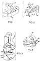
- Fig. 1 is an exploded perspective view of the cast base and a die segment with two dowel pins protruding therefrom, according to the prior art;
- Fig. 2 is an exploded perspective view of the cast base with a pin receiving sleeve inserted in a hole formed in the cast base and a removable die with a pin therein, according to another system of the prior art;
- Fig. 3 is an exploded perspective view of the system for coupling the cast base and the model die according to the present invention;
- Figs. 4 to 6 show the steps of making of the disc and sleeve system of the invention;
- Fig. 7 is a perspective view of the disc and sleeve coupling assembly of the invention;
- Fig. 8 is a perspective view of the sleeve with portions thereof cut away;
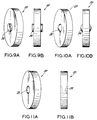
- Figs. 9A to 12E show various modifications of the discs;
- Fig. 13 is a front view, partially in section, of a device for sawing a semi-circular cuts into the lower surface of the model; and
- Fig. 14 shows the removal and re-insertion of a die section into the model, using the disc-and-sleeve assembly according to the invention.
- Referring now to the drawings in detail, Fig. 1 illustrates a commonly used dowel pin system, in which two
parallel pins 2 extending from the lower surface of adie segment 10 of a dental model are received in twocorresponding holes 4 formed in themodel base 12. In the PINDEXR two round parallel sided pins would be used and plastic sleeves would be cast in themodel base 12 to receive the pins. Typically, one short pin and one long pin would be used. - Fig. 2 illustrates a post and sleeve system as is described in copending application Serial No. 076,640 filed and assigned to the assignee of the present invention, which is a form of the PINDEXR system. In this case an elongated substantially cylindrical body portion of a
pin 14 has two diametrically opposing radially projectingribs 16 extending along the length of thebody portion 14 tangentially thereto. Thepin 14 is received in a sleeve orbushing 18 which is then cast into thebase 12. The sleeve has a bore of a shape corresponding to the body portion of thepin 14 so that thepin 14 snugly fits within thebushing 18 to form a composite assembly, which is easily disassembled when die 10 is to be removed from thebase 12.Ribs 16 form alignment means for the reinsertion of thedie section 10 onto thecast base 12 and prevent the die from turning when the latter is remounted on the base. - Referring now to Fig. 3, it will be seen that the disc and sleeve arrangement according to the present invention includes a
disc 20 inserted into thedie segment 10 with a part of the disc projecting downwardly from alower surface 22 of thedie 10. Twoknobs 24 are provided at opposing sides of thedisc 20. The second part of the coupling arrangement is constituted by asleeve 26 cast within thebase 12 and which snugly receives the projecting portion ofdisc 20 as will be described in detail below. - With reference to Figs. 4 to 6 it will be seen that in order to facilitate manufacture of the dental model with the coupling system according to the invention, the
underside surface 30 of adental model 40 which will eventually be cut into a number of segments or dies 10 is formed with a plurality ofcuts 32 circumferentially spaced apart from each other.Cuts 32 are substantially semi-circular in shape and are made by a tool designed for the task.Discs 20 are then inserted and secured intocuts 32 as shown in Fig. 5.Cuts 32 sawed in the ground plane of themodel 40 are maintained vertical and parallel to each other. The number of the cuts is selected such that at least one cut is located in each part or die which would be removable in the model. Thedisc 20 is then secured in each cut 32 as illustrated in Fig. 5.Discs 20 may be fixed incuts 32 by means of cement or any other adequate adhesive material.Cuts 32 are easy to make and their spacing can be easily selected depending on the segments or dies 10 to be removed from the model to be worked on. Additionally, only one cut per die segment is needed. The discs are formed such that only the semi-circular upper portions fit into the cuts. The bottom portions project from the bottom surface, as shown in Fig. 5. Fig. 6 then illustrates thesleeve 26 snapped on the projecting part ofdisc 20. - As best seen in Figs. 7 and 8,
sleeve 26 includes a substantially cylindricalelongated tail portion 28 which merges into aU-shaped head portion 34 having a concaveinner surface 35 and terminated with a housing frame 36.Head portion 34 is formed with a semicircular chamber 38 interior of the frame 36 into which the portion ofdisc 20 protruding from thedie 10 is received. Twosemi-circular recesses 42 of a configuration mating that of theknobs 24 are provided at two longitudinal internal walls of the housing frame 36.Depressions 42 are slightly greater than a semicircle so that thearcuate tips knobs 24 when the protruding portion ofdisc 20 is received into the semi-circular chamber 38 ofsleeve 26. - After
sleeves 26 are snapped onto thediscs 20, embedded in thedental model 40, as shown in Fig. 6, a stone material is poured onto the base of themodel 40 with the disc and sleeve assemblies thereon to form a cast base portion which will support the model. The model will be later cut into segments or dies and each die will be capable of remounting onto the base with the aid of the disc and sleeve arrangements. - Housing frame 36 provided at the upper end of
sleeve 26 is of a substantially rectangular configuration and has a stabilizing flat enlargedupper flange 44 which in assembly seats onto the cast base and forms part of the smooth planar surface of the cast base. This flange rests on theunderside 30 of thecast 40. The flange assists in supporting thesleeve 26 in its vertical position when the stone material or plaster is poured over themodel 40 to cast thebase 60. TheU-shaped head portion 34 and its flange 36 have externally protrudinglugs sleeve 26 and forming means to securely retain the sleeve within the stone material.Lugs upper surface - In assembly, interior chamber 38 snugly accommodates the portion of
disc 20 protruding from theunderside 30 of themodel 40. The thickness ofwalls 52 of theU-shaped head portion 34 is selected so as to be sufficient to reliably hold the protrudingportion 54 ofdisc 20 when the dies 10 of themodel 40 are mounted on thecast base 60. At the same time they must be sufficiently flexible to permit extraction of this protruding portion from thehead portion 34 of thesleeve 26 when adie segment 10 is removed fromcast base 60. The depth of the interior chamber 38 is selected so that approximately three fifths of thedisc 20 is inserted in the recess in the assembled position of the arrangement while two fifths ofdisc 20 is embedded incast 40. Accordingly, as best seen in Fig. 7, thedisc protruding portion 54 snugly fits within thesleeve 26 to form a composite assembly. - Figs. 9 to 12 illustrate various modifications of the
disc 20. As best seen in Figs. 9A and 9B,disc 20 is of a substantially circular configuration and has twocylindrical knobs 24 formed, preferably by casting, at two diametrically opposing sides of the disc for a snap fit into two correspondingly diametrically opposingdepressions 42 ofsleeve 26, as has been described above. - The embodiment of Figs. 10A and 10B differs from that of Figs. 9A and 9B in that knobs 24 are substantially semi-spherical. It is apparent that
depressions 42 in thesleeve 26 for accommodating such knobs would also be of semi-spherical configuration mating that ofknobs 24. - Figs. 11A and 11B depict yet another variant of the disc structure.
Semi-spherical grooves 25 are formed at two diametrically opposing sides of thecircular disc 20, which grooves in the assembled state ofdisc 20 with thesleeve 26 will receive corresponding semi-spherically shaped projections provided at two opposite internal faces of the frame 38 ofhead portion 34 ofsleeve 26 The semi-spherical projections on the sleeve would snap into the grooves on the disc to provide a snug fit of the disc within the sleeve to form a composite assembly when any die segment is remounted on thecast base 60. - Fig. 12A shows yet another variation of the
disc 20 inserted in thehole 32 of themodel 40 and adapted to snugly fit in a corresponding sleeve embedded in thecast base 60.Disc 20 in this embodiment is an elongated, substantially flat element, the upper portion 62 of which again has a semi-circular cross-section to fit in the same semi-circular saw cut 32 previously described. However, instead of a semi-circular lower portion which would project from the bottom of the model there is now provided a lowerelongated portion 64 which tapers downwardly. This elongated taperingportion 64 would be accommodated in a correspondingly shaped recess in a sleeve to be snugly fit therein in the assembled condition and permits easy pulling ofelongated portion 64 from the sleeve to remove a respective die segment from thecast base 60. The projecting knobs 24 would still be used to snap fit the disc into the sleeve. - Fig. 12B illustrates a
disc element 20 which again includes a disc-shapedupper portion 66 insertable in the semi-circular saw cut 32 (Fig. 4) and now includes an elongated protruding rod-like portion 68 joined with the disc-shapedportion 66 and being of the same thickness therewith. The twoknobs 24 are provided for fitting in respective depressions ofsleeve 26 for snap fitting the disc into the sleeve. The sleeve would include a chamber to receive the rod-like projection. - In the embodiment of Fig. 12C, the
internal element 20 of the disc-and-sleeve assembly again includes the disc-shapedportion 70 insertable into the semi-circular saw cut 32 of themodel 40, and now includes anelongated portion 72 of a substantially pyramidal configuration sloping towards adistal end 74 which forms an apex of the pyramid.Knobs 24 are formed at the upper edge ofelongated portion 72 in the manner similar to that of the aforedescribed embodiments. - Fig. 12D depicts a top plan view of another
disc element 20 which includes a disc-shapedportion 80 and a substantiallytriangular portion 82 which would extend downwardly from the disc in a manner similar to that of Figs. 12A-12C. The cross-sectional triangular shape has one end 84 pointed . Twoknobs 24 of a substantially cylindrical shape are formed at two opposite sides of disc-shapedportion 80. Disc-shapedportion 80 would be inserted in saw cut 32 while the triangular piece orportion 82 would be accommodated in a corresponding recess of the sleeve. - Fig. 12E shows a top plan view of a still another version of the
internal disc element 20. Theelement 20 again includes a disc-shapedportion 90 and an elongated element projecting therefrom in a manner similar to Figs. 12A-12C. The projection portion has a cross-sectional configuration shown at 92 which is a substantially rectangular configuration with oneend 94 being curved. The top ofportion 92 forms a flange below the disc which is received in a recess of the corresponding sleeve of the assembly.Knobs 24 could snap fit in two opposing grooves of the sleeve. - In all the embodiments of the internal or male element of the snap-in assembly of the invention, the disc-shaped portion of each element ensures its easy insertion in the respective semicircular saw cut 32 of the dental model while the protruding portion of this internal element is received in the base. The protruding portion may be the remaining part of a circular disc or a vertically extending rod like portion. The combination of the disc and sleeve ensures a reliable seating of the segment into the base and permits easy removability of the segments. Nevertheless in each case only a single cut is required in each die segment and into which the semi-circular disc is inserted. This provides orientation for returning the segment. Also, the presence of the knobs provide good lock means for locking of the disc in the sleeve. In all exemplified embodiments, the portion of the
internal member 20 received and secured in the saw cut 32 has a semi-circular configuration mating that of each saw cut 32 formed in the underside ofmodel 40. - It should be noted that in the embodiment of Figs. 9A to
11B disc 20 may be inserted intosleeve 26 in two 180o opposite positions. On the other hand, the vertically extending portions of the embodiments of Figs. 12A - 12E constitute orientation means which ensure the insertion of theinternal disc elements 20 into thesleeve 26 in a single insertion position. In all the embodiments, however, a reliable snap lock of the disc and sleeve assembly is provided to connect the die segment to the said base and an easy disassembling of these two parts to remove the die segment from the cast base. - It should be emphasized that in all the embodiments only a single hole and a single snap-in assembly of the invention are necessary for each die segment to be removed from and remounted on the cast base whereas in other prior art systems at least two holes and two pins are necessary for a proper orientation and removable connection of a die segment to the cast base. Furthermore, the continuous reinsertion of the cylindrical pins into the sleeves may cause the assembly to become loose and shaky. These disadvantages are eliminated with the snap-fit disc-and-sleeve assembly according to the invention. Only a single sawing operation is required to produce
semi-circular cut 32 in the underside of the dental model according to the present invention and the snap fit ensures a tight fit. - Fig. 13 schematically illustrates a rotary saw assembly which can be used for making the saw cuts into the underside of the
model 40. The rotary saw of Fig. 13 designated at 100 includes ahousing 102 which defines ahousing compartment 104 in which a motor-driven rotary saw 106 is accommodated. A vertically movable work table 110 supports thereon thecast model 40 onto which the saw cuts are to be made Aslit 112 is provided in a supportingplate 114 of the work table 110 so that the cutter or sawblade 108 can extend upwardly through the slit as the work table descends. In the normal, uppermost position, as shown in solid line in Fig. 13, the blade is completely recessed beneath the work table and directly under theslit 112 in the supportingplate 114. As the work table is lowered by depression of the model onto the supportingplate 114 the blade becomes exposed as it emerges upwardly through the slit above the top surface ofplate 114, as shown in dotted line in Fig. 13, and the saw cut into the underside ofmodel 40 is performed. Depending from atransverse arm 116 of anupper part 118 of the work table rigidly connected to the supportingplate 114, is abeam light 120 which is focused so that it is directly over a section of the die to be segmented and identifies the cutting point at the diametric top of the rotary blade.Model 40 may then be shifted horizontally to position the model such that a next portion to be segmented is oriented over the saw blade. - Fig. 14 illustrates a working
cast 125 which includesbase 60 andmodel 40 mounted thereon. - As seen in Fig. 14 the die 10 (shown in dotted line) carrying the
single disc 20 therein can be remounted onto thecast base 60 whereby thedisc 20 snap-fits in thesleeve 26 assigned thereto. In this manner an initial position ofdie segment 10 relative to the base and relative to the orientation of the protruding disc-portion ofdisc 20 in thesleeve 26. Due toknobs 24 received in the respective depressions of thesleeve 26 thedie section 10 will fit snugly on the base 60 as the die section is pushed into place. As also shown in Fig. 14 thecylindrical tail 28 of thesleeve 26 projects into anotch 130 cut onto the underside ofbase 60 of the workingcast 125. Pushing up on the distal end oftail 28 of the sleeve would spread the arms on each side of the head portion 36 of the sleeve to facilitate release ofdisc 20 from the sleeve and thus the removal ofdie segment 10 from thebase 60. The disc and the sleeve may be made of plastic or metal material as is well known in this field. - There has been disclosed heretofore the best embodiment of the invention presently contemplated. However, it is to be understood that various changes and modifications may be made thereto without departing from the scope of the invention as defined in the appended claims.
Claims (10)
- A dental pin and sleeve assembly for removably-coupling a die section of a dental model into a cast base, the assembly comprising:
a pin member (20) including an internal portion for securement within said die section and an exterior portion protruding from said die section to depend therefrom, said internal portion being of a substantially semi-circular configuration; and
a sleeve member (26) for securement within said cast base, said sleeve member including a head portion (34) having a chamber (38) which is opened at an upper face of said cast base to wholly receive said exterior protruding portion of said pin member when said die section is coupled to said cast base. - A dental pin and sleeve assembly as in claim 1, wherein said exterior portion and said head portion include cooperating lock means (24, 39, 41, 42) for providing a releasable snap-fit lock of said exterior portion into said head portion when said die section is coupled into said cast base.
- A dental pin and sleeve assembly as in claim 1, wherein said sleeve member comprises a substantially cylindrical tail portion (28) depending from said head portion.
- A dental pin and sleeve assembly as in claim 1, wherein said exterior portion is of a substantially semi-circular configuration and constitutes with said internal semicircular portion a complete disc.
- A dental pin and sleeve assembly as in claim 1, wherein said head portion (34) is a frame (36) which having said internal chamber (38) for matingly receiving said exterior protruding portion.
- A dental pin and sleeve assembly as in claim 5, wherein said chamber (38) is semi-circular.
- A dental pin and sleeve assembly as in claim 2, wherein said lock means include two knobs (24) positioned at two opposite sides of said exterior protruding portion and two correspondingly shaped grooves (42) formed in said sleeve member and receiving said two knobs, respectively.
- A dental pin and sleeve assembly as in claim 1, wherein said head portion is U-shaped.
- A dental pin and sleeve assembly as in claim 1, wherein said head portion (34) is formed with outwardly protruding lugs (48, 50) positioned at two opposite sides thereof for retaining said sleeve within said cast base.
- A method of making a model of teeth wherein die portions (10) of the model may be removed and remounted from a base (12), characterised in that the method comprises the steps of cutting a plurality of substantially semi-circular cuts in an underside (30) of the model (40) opposite to that formed with the teeth, fixing a disc-shaped element (20) in each cut so that a portion of said element extends normal to and outwardly from said underside of the model, mounting on outwardly extending portions of disc-shaped elements sleeves (26) each having a recess (38) matingly receiving said portion of a respective disc-shaped element, pouring a cast material over said model with said disc-shaped elements and said sleeves thereon to form the base (12), allowing said material to harden for securing each sleeve in said base, removing said model together with said elements from said hardened base, and cutting said model (40) into die portions (10) so that each die portion includes at least one disc-shaped element protruding therefrom, said die portions being remountable on said base by insertion of said portion of each disc-shaped element into said recess of a respective sleeve.
Applications Claiming Priority (3)
| Application Number | Priority Date | Filing Date | Title |
|---|---|---|---|
| US07/306,949 US5087197A (en) | 1989-02-06 | 1989-02-06 | Disc and sleeve assembly for coupling die segments of a dental model to a base |
| US306949 | 1989-02-06 | ||
| PCT/US1990/000293 WO1990008515A1 (en) | 1989-02-06 | 1990-01-16 | Assembly for coupling segments to a base |
Publications (3)
| Publication Number | Publication Date |
|---|---|
| EP0458810A1 EP0458810A1 (en) | 1991-12-04 |
| EP0458810A4 EP0458810A4 (en) | 1992-03-18 |
| EP0458810B1 true EP0458810B1 (en) | 1994-09-14 |
Family
ID=23187592
Family Applications (1)
| Application Number | Title | Priority Date | Filing Date |
|---|---|---|---|
| EP90902459A Expired - Lifetime EP0458810B1 (en) | 1989-02-06 | 1990-01-16 | Assembly for coupling segments to a base |
Country Status (7)
| Country | Link |
|---|---|
| US (1) | US5087197A (en) |
| EP (1) | EP0458810B1 (en) |
| AU (1) | AU628131B2 (en) |
| DE (1) | DE69012553T2 (en) |
| ES (1) | ES2060143T3 (en) |
| FI (1) | FI95767C (en) |
| WO (1) | WO1990008515A1 (en) |
Families Citing this family (6)
| Publication number | Priority date | Publication date | Assignee | Title |
|---|---|---|---|---|
| DE4113651A1 (en) * | 1991-04-26 | 1992-10-29 | Schreiber Hans | METHOD AND DEVICE FOR PRODUCING SPECIAL DENTAL SAW CUTTING MODELS |
| USRE35263E (en) * | 1992-06-19 | 1996-06-04 | The Silva Group, Inc. | Method and apparatus for fabricating dental models |
| US5573397A (en) * | 1993-07-06 | 1996-11-12 | S-Tec, Inc. | Method for creating a universal mount for dental articulators |
| US5876204A (en) * | 1997-11-25 | 1999-03-02 | Sulzer Calcitek Inc. | Dental implant positioning guide |
| US20220258322A1 (en) * | 2012-02-21 | 2022-08-18 | Align Technology, Inc. | Dental models and related methods |
| US9375298B2 (en) * | 2012-02-21 | 2016-06-28 | Align Technology, Inc. | Dental models and related methods |
Family Cites Families (3)
| Publication number | Priority date | Publication date | Assignee | Title |
|---|---|---|---|---|
| US2851728A (en) * | 1954-07-14 | 1958-09-16 | Weinstein | Interlockable dental dowel pin and repositioning gauge and method of using |
| US4054995A (en) * | 1976-05-03 | 1977-10-25 | Yoshida Harry Y | Pin with sleeve for making dental prosthesis |
| US4205443A (en) * | 1978-05-08 | 1980-06-03 | Ipco Hospital Supply Corporation | Two-part dowel pin and tool therefor |
-
1989
- 1989-02-06 US US07/306,949 patent/US5087197A/en not_active Expired - Lifetime
-
1990
- 1990-01-16 DE DE69012553T patent/DE69012553T2/en not_active Expired - Fee Related
- 1990-01-16 ES ES90902459T patent/ES2060143T3/en not_active Expired - Lifetime
- 1990-01-16 EP EP90902459A patent/EP0458810B1/en not_active Expired - Lifetime
- 1990-01-16 AU AU49518/90A patent/AU628131B2/en not_active Ceased
- 1990-01-16 WO PCT/US1990/000293 patent/WO1990008515A1/en not_active Ceased
-
1991
- 1991-08-05 FI FI913725A patent/FI95767C/en active
Also Published As
| Publication number | Publication date |
|---|---|
| DE69012553T2 (en) | 1995-02-02 |
| DE69012553D1 (en) | 1994-10-20 |
| FI95767B (en) | 1995-12-15 |
| EP0458810A4 (en) | 1992-03-18 |
| US5087197A (en) | 1992-02-11 |
| ES2060143T3 (en) | 1994-11-16 |
| FI913725A0 (en) | 1991-08-05 |
| FI95767C (en) | 1996-03-25 |
| AU4951890A (en) | 1990-08-24 |
| AU628131B2 (en) | 1992-09-10 |
| WO1990008515A1 (en) | 1990-08-09 |
| EP0458810A1 (en) | 1991-12-04 |
Similar Documents
| Publication | Publication Date | Title |
|---|---|---|
| CA1171210A (en) | Mold for dental models | |
| US4203219A (en) | Dental model assembly and production method | |
| US4459110A (en) | Dowel pin locator assembly and method of making positive dental models with removable dies | |
| US4127939A (en) | J-Shaped pin for making dental prosthesis with means for debris escape | |
| US6884068B2 (en) | Dental model base configured for customized aperture formation | |
| US6425759B1 (en) | Dental cast tray assembly | |
| US5100317A (en) | Device and method for fabricating a prosthesis | |
| US5425636A (en) | Articulator for dental mold | |
| US6106284A (en) | Dental cast tray assembly | |
| US4252523A (en) | Apparatus and method for forming dental models | |
| WO1989000838A1 (en) | Dental pin and bushing assembly | |
| US4997370A (en) | Dental model alignment device | |
| US7338283B2 (en) | Dental prostheses modeling system with symmetric double-well trays slidably mountable to articulator | |
| US4238189A (en) | Method and apparatus for making in a single operation a base and dental model including a tooth die with an integral bayonet type mounting pin | |
| US5087197A (en) | Disc and sleeve assembly for coupling die segments of a dental model to a base | |
| US3521354A (en) | Dowel assembly and method | |
| CA2435766A1 (en) | Improved dental model base assembly | |
| US4054995A (en) | Pin with sleeve for making dental prosthesis | |
| US20030036035A1 (en) | Removable analog | |
| US6439884B1 (en) | Dental cast tray assembly | |
| US20060210944A1 (en) | Dental modeling and articulating system and method | |
| US3875665A (en) | Dual pin for prosthodontic casts | |
| US4129281A (en) | Dowel receiving core for casting dental restorations | |
| US6712609B2 (en) | Supporting structure for a dental model and a method for forming thereof | |
| US4288220A (en) | Dental casts having vertical adjustments |
Legal Events
| Date | Code | Title | Description |
|---|---|---|---|
| PUAI | Public reference made under article 153(3) epc to a published international application that has entered the european phase |
Free format text: ORIGINAL CODE: 0009012 |
|
| AK | Designated contracting states |
Kind code of ref document: A1 Designated state(s): CH DE DK ES FR GB LI NL SE |
|
| 17P | Request for examination filed |
Effective date: 19911008 |
|
| RAP1 | Party data changed (applicant data changed or rights of an application transferred) |
Owner name: COLTENE/WHALEDENT, INC. |
|
| A4 | Supplementary search report drawn up and despatched |
Effective date: 19920128 |
|
| AK | Designated contracting states |
Kind code of ref document: A4 Designated state(s): CH DE DK ES FR GB LI NL SE |
|
| 17Q | First examination report despatched |
Effective date: 19931213 |
|
| RAP1 | Party data changed (applicant data changed or rights of an application transferred) |
Owner name: COLTENE/WHALEDENT, INC. |
|
| GRAA | (expected) grant |
Free format text: ORIGINAL CODE: 0009210 |
|
| AK | Designated contracting states |
Kind code of ref document: B1 Designated state(s): CH DE DK ES FR GB LI NL SE |
|
| PG25 | Lapsed in a contracting state [announced via postgrant information from national office to epo] |
Ref country code: DK Effective date: 19940914 |
|
| ET | Fr: translation filed | ||
| REF | Corresponds to: |
Ref document number: 69012553 Country of ref document: DE Date of ref document: 19941020 |
|
| REG | Reference to a national code |
Ref country code: ES Ref legal event code: FG2A Ref document number: 2060143 Country of ref document: ES Kind code of ref document: T3 |
|
| EAL | Se: european patent in force in sweden |
Ref document number: 90902459.8 |
|
| PLBE | No opposition filed within time limit |
Free format text: ORIGINAL CODE: 0009261 |
|
| STAA | Information on the status of an ep patent application or granted ep patent |
Free format text: STATUS: NO OPPOSITION FILED WITHIN TIME LIMIT |
|
| 26N | No opposition filed | ||
| REG | Reference to a national code |
Ref country code: GB Ref legal event code: IF02 |
|
| PGFP | Annual fee paid to national office [announced via postgrant information from national office to epo] |
Ref country code: NL Payment date: 20041229 Year of fee payment: 16 |
|
| PGFP | Annual fee paid to national office [announced via postgrant information from national office to epo] |
Ref country code: FR Payment date: 20050117 Year of fee payment: 16 |
|
| PGFP | Annual fee paid to national office [announced via postgrant information from national office to epo] |
Ref country code: SE Payment date: 20050120 Year of fee payment: 16 |
|
| PGFP | Annual fee paid to national office [announced via postgrant information from national office to epo] |
Ref country code: CH Payment date: 20050124 Year of fee payment: 16 |
|
| PGFP | Annual fee paid to national office [announced via postgrant information from national office to epo] |
Ref country code: ES Payment date: 20050208 Year of fee payment: 16 |
|
| PGFP | Annual fee paid to national office [announced via postgrant information from national office to epo] |
Ref country code: GB Payment date: 20060113 Year of fee payment: 17 |
|
| PG25 | Lapsed in a contracting state [announced via postgrant information from national office to epo] |
Ref country code: ES Free format text: LAPSE BECAUSE OF NON-PAYMENT OF DUE FEES Effective date: 20060117 Ref country code: SE Free format text: LAPSE BECAUSE OF NON-PAYMENT OF DUE FEES Effective date: 20060117 |
|
| PG25 | Lapsed in a contracting state [announced via postgrant information from national office to epo] |
Ref country code: CH Free format text: LAPSE BECAUSE OF NON-PAYMENT OF DUE FEES Effective date: 20060131 Ref country code: FR Free format text: LAPSE BECAUSE OF NON-PAYMENT OF DUE FEES Effective date: 20060131 Ref country code: LI Free format text: LAPSE BECAUSE OF NON-PAYMENT OF DUE FEES Effective date: 20060131 |
|
| PGFP | Annual fee paid to national office [announced via postgrant information from national office to epo] |
Ref country code: DE Payment date: 20060228 Year of fee payment: 17 |
|
| PG25 | Lapsed in a contracting state [announced via postgrant information from national office to epo] |
Ref country code: NL Free format text: LAPSE BECAUSE OF NON-PAYMENT OF DUE FEES Effective date: 20060801 |
|
| REG | Reference to a national code |
Ref country code: CH Ref legal event code: PL |
|
| EUG | Se: european patent has lapsed | ||
| NLV4 | Nl: lapsed or anulled due to non-payment of the annual fee |
Effective date: 20060801 |
|
| REG | Reference to a national code |
Ref country code: FR Ref legal event code: ST Effective date: 20060929 |
|
| REG | Reference to a national code |
Ref country code: ES Ref legal event code: FD2A Effective date: 20060117 |
|
| PG25 | Lapsed in a contracting state [announced via postgrant information from national office to epo] |
Ref country code: DE Free format text: LAPSE BECAUSE OF NON-PAYMENT OF DUE FEES Effective date: 20070801 |
|
| GBPC | Gb: european patent ceased through non-payment of renewal fee |
Effective date: 20070116 |
|
| PG25 | Lapsed in a contracting state [announced via postgrant information from national office to epo] |
Ref country code: GB Free format text: LAPSE BECAUSE OF NON-PAYMENT OF DUE FEES Effective date: 20070116 |