EP0458639B1 - Servo valve control method and apparatus - Google Patents
Servo valve control method and apparatus Download PDFInfo
- Publication number
- EP0458639B1 EP0458639B1 EP91304690A EP91304690A EP0458639B1 EP 0458639 B1 EP0458639 B1 EP 0458639B1 EP 91304690 A EP91304690 A EP 91304690A EP 91304690 A EP91304690 A EP 91304690A EP 0458639 B1 EP0458639 B1 EP 0458639B1
- Authority
- EP
- European Patent Office
- Prior art keywords
- servo
- coil
- control
- normal
- amplifier
- Prior art date
- Legal status (The legal status is an assumption and is not a legal conclusion. Google has not performed a legal analysis and makes no representation as to the accuracy of the status listed.)
- Expired - Lifetime
Links
- 238000000034 method Methods 0.000 title claims description 20
- 230000005856 abnormality Effects 0.000 claims description 60
- 230000002159 abnormal effect Effects 0.000 claims description 32
- 238000001514 detection method Methods 0.000 claims description 20
- 239000000446 fuel Substances 0.000 claims description 14
- 230000004044 response Effects 0.000 claims description 8
- 238000000926 separation method Methods 0.000 claims description 5
- 230000003321 amplification Effects 0.000 claims 2
- 238000003199 nucleic acid amplification method Methods 0.000 claims 2
- 238000003745 diagnosis Methods 0.000 description 17
- 229920006395 saturated elastomer Polymers 0.000 description 13
- 230000006870 function Effects 0.000 description 6
- 238000012545 processing Methods 0.000 description 3
- 230000009471 action Effects 0.000 description 2
- 238000007796 conventional method Methods 0.000 description 1
- 230000001419 dependent effect Effects 0.000 description 1
- 238000012544 monitoring process Methods 0.000 description 1
- 238000010248 power generation Methods 0.000 description 1
- 230000008569 process Effects 0.000 description 1
- 230000009467 reduction Effects 0.000 description 1
- 230000002194 synthesizing effect Effects 0.000 description 1
- 230000008646 thermal stress Effects 0.000 description 1
- 238000012546 transfer Methods 0.000 description 1
Images




Classifications
-
- G—PHYSICS
- G05—CONTROLLING; REGULATING
- G05B—CONTROL OR REGULATING SYSTEMS IN GENERAL; FUNCTIONAL ELEMENTS OF SUCH SYSTEMS; MONITORING OR TESTING ARRANGEMENTS FOR SUCH SYSTEMS OR ELEMENTS
- G05B9/00—Safety arrangements
- G05B9/02—Safety arrangements electric
- G05B9/03—Safety arrangements electric with multiple-channel loop, i.e. redundant control systems
-
- Y—GENERAL TAGGING OF NEW TECHNOLOGICAL DEVELOPMENTS; GENERAL TAGGING OF CROSS-SECTIONAL TECHNOLOGIES SPANNING OVER SEVERAL SECTIONS OF THE IPC; TECHNICAL SUBJECTS COVERED BY FORMER USPC CROSS-REFERENCE ART COLLECTIONS [XRACs] AND DIGESTS
- Y10—TECHNICAL SUBJECTS COVERED BY FORMER USPC
- Y10T—TECHNICAL SUBJECTS COVERED BY FORMER US CLASSIFICATION
- Y10T137/00—Fluid handling
- Y10T137/8593—Systems
- Y10T137/86493—Multi-way valve unit
- Y10T137/86574—Supply and exhaust
- Y10T137/86582—Pilot-actuated
- Y10T137/86614—Electric
Definitions
- the control system for the triple-coil servo valve has been arranged in such a manner that the output from each of the controllers is supplied to each of the coils via the servo amplifier so as to control the triple-coil servo valve by the total ampere's turn of the coils. Therefore, in a case where there is a fault in any one of the three systems, the residual two systems compensate the faulty system to continue the desired operation. However, if there are faults in the two systems, a decision is made that the system has been tripped.
- triple-coil serve valve a structure, which is arranged in such a manner that its actuator is in the form of a tripled system, has been disclosed in "TRIPLE REDUNDANT ELECTROMECHANICAL LINEAR ACTUATOR AND METHOD"; US patent number 4,521,707.
- the triple-coil servo valve 6 for bypass-controlling the flow rate of the fuel is controlled by a tripled system control system of a servo valve control apparatus 200, the tripled system control system being composed of a controller 7 of system A, a controller 8 of system B and a controller 9 of system C.
- a tripled system control system being composed of a controller 7 of system A, a controller 8 of system B and a controller 9 of system C.
- controllers 7, 8 and 9 carries out the same calculations.
- the operation of the servo valve 6 is controlled in accordance with the result of synthesizing the values obtained from the above-described calculations.
- the feedback value diagnosis portion 33 for diagnosing the servo coil electric current makes a comparison between the control command value 20 of the controller and a feedback value 47 of the servo coil electric current so as to diagnose the abnormality of the servo coil or the servo amplifier.
- the abnormality of the servo coil is exemplified by a disconnection of the servo coil.
- the feedback value 47 of the coil electric current is zero.
- the feedback value 47 of the coil electric current is a saturated electric current value.
- the abnormality detection device 31 causes each of the controllers to diagnose the abnormality of each of the components in the control system, for example, the abnormality of the controller, that of the servo amplifier, that of the servo coil and that of the servo position detector.
- the servo valve control apparatus 200 shown in Figs. 1A ⁇ 1C are arranged in such a manner that the abnormality of the controller, that of the servo amplifier, that caused from the disconnection of the servo coil and that of the servo position detector are detected of the abnormality detection device 31 of each of the controllers. Furthermore, servo amplifier output separation switches 35, 36 and 37 for omitting the faulty component from the operation of controlling the plant are provided. In addition, in order to effectively operate the normal systems, a compensating means comprising a sub-amplifier input selection switch 38, a sub-amplifier 39 and a sub-amplifier output selection switch 40 is provided.
- the output from the sub-amplifier 39 is transmitted to the system A, which is a system having the normal servo coil (in this state, although the output may be transmitted to the system A or B, an assumption is made that the output to the system A is made). Therefore, the electric current of the servo coil of the system A compensates the saturated electric current of the system B as well as the electric current of the servo coil of the system C when the servo amplifier of the system B is saturated. As a result, the continuation of the operation can be enabled safely.
- the servo amplifier is provided for each of the systems A, B and C.
- the input at this time is performed in such a manner that the input of the normal controller is selected by the input switch 41. Then, a flow of the input performed in the amplifier of the system A will now be described with reference to Fig. 8.
- the amplifier of the system A selects the controller of the system A. In a case where the controller of the system A is abnormal, determinations whether or not the controller of the system B and that of the system C are sequentially made. As a result, the input of the normal controller is selected by the amplifier input switch 41.
- the amplifier of the system B similarly receives the control command value 20 of the normal controller after the determinations about the systems ⁇ B>, ⁇ C> and ⁇ A> have been sequentially made.
- the amplifier of the system C similarly receives the control command value 20 of the normal controller after the determinations about the systems ⁇ C>, ⁇ A> and ⁇ B> have been sequentially made.
- a 1-coil gain is selected by the gain switch 42 so that an output to the coil of the system A is made by the amplifier output switch 43. Subsequently, the amplifiers of the systems B and C are operated similarly.
Landscapes
- Physics & Mathematics (AREA)
- General Physics & Mathematics (AREA)
- Engineering & Computer Science (AREA)
- Automation & Control Theory (AREA)
- Safety Devices In Control Systems (AREA)
Description
- The present invention relates to a servo valve control method and apparatus, and, more particularly, to a servo valve control method and apparatus which employs a triplex controller as a unit for controlling a triple-coil servo valve, which is the subject to be controlled, the servo valve control method and apparatus being able to satisfactorily control the turbine in a thermal power plant, an atomic power plant or the like.
- There has been known a method of controlling the triple-coil servo valve which is constituted as disclosed in "The SPEEDTRONIC MARK IV control (tm), a distributed fault tolerant gas turbine control system."; ASME 83-GT-106 in such a manner that its control system comprising coils, a servo amplifier and controllers is tripled.
- The control system for the triple-coil servo valve has been arranged in such a manner that the output from each of the controllers is supplied to each of the coils via the servo amplifier so as to control the triple-coil servo valve by the total ampere's turn of the coils. Therefore, in a case where there is a fault in any one of the three systems, the residual two systems compensate the faulty system to continue the desired operation. However, if there are faults in the two systems, a decision is made that the system has been tripped.
- A similar contents has been disclosed in "Turbine Digital Control and Monitoring (DCM) system"; ASME 88-JPGC/Pwr-33.
- A 2-out of 3-logic system has been disclosed in "DIGITAL 2-OF-3 SELECTION AND OUTPUT CIRCUIT"; US Patent Number 4,857,762. In this literature, a method of driving the relay of a circuit, which employs an optocoupler of the 2-out of 3-logic structure, that is a digital 2-out of 3-logic structure, has been disclosed. According to the above-described disclosure, although a fault signal is selected in a case where faults have been found in the two systems, no description has not been made about an adjustment control signal.
- EP-A-0275362 discloses a safety control system having four signal processing channels. Two independent switching circuits are connected to each of the four signal processing channels in such a way that they constitute a two-out-of-four logic circuit. When a fault is detected by two of the four processing channels, the switching circuits actuate a scrammer to shut down the nuclear plant.
- EP-A-0202052 discloses a protection system in which signals are distributed to redundant trip logic processors. Each of these performs predetermined logic functions and, upon appropriate inputs, generates a trip signal which is supplied to voters. The voters generate an actuation signal based upon a vote of their inputs to activate a reactor protection device.
- Furthermore, as for the triple-coil serve valve, a structure, which is arranged in such a manner that its actuator is in the form of a tripled system, has been disclosed in "TRIPLE REDUNDANT ELECTROMECHANICAL LINEAR ACTUATOR AND METHOD"; US patent number 4,521,707.
- In addition, a serve valve control system arranged in such a manner that its controller is tripled has been disclosed in "MULTISYSTEM CONTROL APPARATUS" (see Japanese Patent Laid-Open No. 59-85501). The above-disclosed structure is arranged to have the tripled controller so that the servo valve can be controlled if the two systems have become faulty. In this state, a standby system, which has been previously provided, is selected in place of the active system. Furthermore, a structure of the triple-coil servo valve control method has been disclosed in "Digital Electric Hydraulic Control Apparatus for Atomic Turbine", Vol. 36, No. 347, August 1985, "Thermal & Atomic Power Generation", which is arranged in such a manner that, if the two coils are disconnected, the residual coil acts to continue the operation. However, the above-described literature has not disclosed a specific means.
Furthermore, no-description has been made about the operation to be performed in a case where the servo amplifier or the controller has become faulty or a system constituted by combining the above-described components has become faulty. - According to any one of the above-described conventional structures, the operation of the plant has been shut down in a case where the two systems of all of the control systems have become faulty and as well as the residual system is normal or in a case where the faulty system partially contains a normal component.
- Since the central control valve of a plant employs the triple-coil servo valve in order to improve reliability, the trip of the triple-coil servo valve usually causes the shutdown of the plant. However, the shutdown of a plant has been usually avoided recently in order to eliminate the social influence.
- Furthermore, since the conventional method of controlling the triple-coil servo valve encounters a disturbance generated in the control system thereof if the controller has become faulty, the servo amplifier output from the control system, which includes the faulty controller, is separated from the overall system. However, in a case where the controller is normal and as well as the servo amplifier has become faulty, the servo amplifier output is not separated because the controller is normal. As a result, a problem arises in that a disturbance will be generated in the control system.
- It would be preferable to enable the continuation of the operation of a plant even if two control systems are abnormal by compensating a residual normal system to operate a triple-coil servo valve.
- It would also be preferable to enable the continuation of the operation of a plant even if a portion of the components of the control system has become faulty by combining the residual normal components or by compensating the same to operate a triple-coil servo valve.
- Another preferred aim would be to separate, in a case where a servo amplifier or a controller is abnormal, the output from the servo amplifier of the control system which includes the abnormality after detecting the abnormality of the servo amplifier or the controller for the purpose of protecting the control system from a disturbance.
- The invention solves the problems mentioned above by the apparatus and methods defined in the appended independent claims.
- Further aspects are set out in the dependent claims.
- Other and further objects, features and advantages of the invention will be appear more fully from the following description.
-
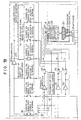
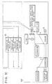
- Figs. 1A, 1B and 1C illustrate the structure of an embodiment of a triple-coil servo valve control apparatus according to the present invention;
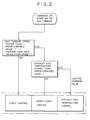
- Fig. 2 is a flow chart for selecting a control command value;
- Fig. 3 illustrates the characteristics of a conventional triple-coil servo;
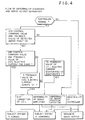
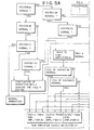
- Fig. 4 is a flow chart for diagnosing abnormalities and separating the output from the servo amplifier;
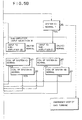
- Figs. 5A and 5B are a flow chart for selecting the I/O to and from a sub-amplifier;
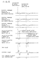
- Fig. 6 illustrates the characteristics of a triple-coil servo embodying the present invention;
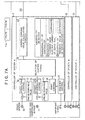
- Figs. 7A and 7B illustrate another embodiment of the present invention;
- Fig. 8 is a flow chart for inputting of an amplifier of system A; and
- Figs. 9A, 9B, 9C and 9D illustrate a flow chart for outputting of the amplifier of the system A.
-
- Embodiments of the invention will now be described.
- Figs. 1A~1C show an embodiment of the structure of a servo
valve control apparatus 200 of agas turbine system 100. Thegas turbine system 100 has acombustor 3 which combusts fuel introduced from outside by afuel transfer pump 1 and high pressure air compressed by acompressor 2, causing high pressure hot gas to be generated. The energy of the generated gas rotates aturbine 4 at high speed, causing a generator 5 to be driven. Consequently, electric energy can be supplied. The output energy from the gas turbine is determined in accordance with the flow rate of the fuel, the flow rate being changed by controlling a triple-coil servo valve 6 for bypass-controlling the flow rate of the fuel. - The triple-
coil servo valve 6 for bypass-controlling the flow rate of the fuel is controlled by a tripled system control system of a servovalve control apparatus 200, the tripled system control system being composed of acontroller 7 of system A, acontroller 8 of system B and acontroller 9 of system C. Each of the above-describedcontrollers servo valve 6 is controlled in accordance with the result of synthesizing the values obtained from the above-described calculations. - Each of the
controllers load control system 14 and an exhaust-gastemperature control system 15 respectively receiving signals from aspeed sensor 10 and an exhaust-gas temperature sensor 11 which are fastened to the body of the gas turbine. Then, the speed/load control system 14 and the exhaust-gastemperature control system 15 make comparisons between the values denoted by received signals and a predeterminedspeed level 12 and a predetermined exhaust-gas temperature level 13 so as to perform the control in such a manner that the predetermined levels are realized. In each of thecontrollers sequence control system 17 so as to be subsequently, together with a control signal transmitted from astart control system 18, received by a controlsignal selection portion 19. The controlsignal selection portion 19 selects the signal of the minimum level, and a control commandvalue calculating portion 45 processes acontrol command value 20 in accordance with the selected signal. The signals left from the selection serve as backup signals with respect to thecontrol command value 20. - A flow chart for an operation in which the
control command value 20 is selected by the controlsignal selection portion 19 is shown in Fig. 2. - The gas turbine is started in response to an issued start command in such a manner that a start control is employed as the
control command value 20 until the gas turbine is able to rotate. Since the speed has not been raised to the predetermined level, the value of a speed/load control is larger than that of the start control. Similarly, since the exhaust-gas temperature has not been raised to a predetermined level, the value of exhaust-gas temperature control is larger than that of the speed/load control and the start control. Therefore, the controlsignal selection portion 19 for selecting the minimum level signal selects the start control as thecontrol command value 20. - When the revolution of the gas turbine reaches the self-rotatable revolution, the speed/load control is selected because the speed has been raised to the predetermined speed. Since the value of the start control at this time is set to be higher than the value of the speed/load control, the commanded value of the speed/load control, which is the minimum value, is selected.
- When the exhaust-gas temperature is raised to be higher than the predetermined level, the exhaust-gas temperature control is selected as the control command value. At this time, each of the start control and the speed/load control serves as a backup.
- The above-described discrimination is made in the control
signal selection portion 19 of the controller by means of software in accordance with the flow chart shown in Fig. 2. - Referring back to Figs. 1A~1C in which the servo
valve control apparatus 200 is shown, thecontrol command value 20 supplied from each of thecontrollers servo amplifiers servo amplifiers feedback signal 25 and thecontrol command value 20 for each of the systems, thefeedback signal 25 being a signal supplied from a servovalve position detector 25 which feeds back the control quantity of an actuator 24 of the triple-coil servo valve 6. Theservo amplifiers servo coils coil servo valve 6 operates atorque motor 29 by the total of driving torque generated in each of the servo coils 26, 27 and 28. As a result, the triple-coil servo valve 6 controls the actuator 24 by operating acylinder 30. - Each of the controllers has an
abnormality detection device 31 which is constituted by a controllerabnormality detection portion 32, a feedbackvalue diagnosis portion 33 for diagnosing the feedback value of a servo coil electric current and a feedbackvalue diagnosis portion 34 for diagnosing the feedback value of the servo position. - The controller
abnormality detection portion 32 possesses a function of a CPU for diagnosing the abnormality of the controller. - The feedback
value diagnosis portion 33 for diagnosing the servo coil electric current makes a comparison between thecontrol command value 20 of the controller and afeedback value 47 of the servo coil electric current so as to diagnose the abnormality of the servo coil or the servo amplifier. The abnormality of the servo coil is exemplified by a disconnection of the servo coil. In this case, thefeedback value 47 of the coil electric current is zero. In a case where the servo amplifier has become faulty, thefeedback value 47 of the coil electric current is a saturated electric current value. - The feedback
value diagnosis portion 34 for diagnosing the feedback value of the servo position makes a comparison between thecontrol command value 20 of the controller and a feedback value 46 of theservo position detector 25 so as to diagnose the abnormality of the servo position detection portion. That is, if there is a fault, thecontrol command value 20 and the feedback value 46 are of different values. - The
abnormality detection device 31 causes each of the controllers to diagnose the abnormality of each of the components in the control system, for example, the abnormality of the controller, that of the servo amplifier, that of the servo coil and that of the servo position detector. - Table 1 shows the abnormality diagnosis means and the contents of the abnormality diagnoses.
Abnormality Abnormality Mode Abnormality Detection means Contents of Detected Abnormality Abnormality of controller Abnormality of controller of system <A> Detected by function of detecting abnormality of controller of system <A> Function of diagnosing abnormality of Computer (CPU) (diagnosed by memory parity, error detection or watch dog timer detection) Abnormality of controller of system <B> Detected by function of detecting abnormality of controller of system <B> Abnormality of controller of system <C> Detected by function of detecting abnormality of controller of system <C> Abnormality of servo amplifier Abnormality of servo amplifier of system <A> Detected by diagnosis of feedback value of coil electric current of system <A> Discriminated by making a comparison between control command value and feedback value of coil electric current (coil electric current becomes saturated to be different from control command value) Abnormality of servo amplifier of system <B> Detected by diagnosis of feedback value of coil electric current of system <B> Abnormality of servo amplifier of system <C> Detected by diagnosis of feedback value of coil electric current of system <C> Abnormality of disconnection of servo coil Abnormality of disconnection of servo coil of system <A> Detected by diagnosis of feedback value of coil electric current of system <A> Discriminated by making a comparison between control command value and feedback value of coil electric current (since servo coil is disconnected, feedback value of electric current is always zero) Abnormality of disconnection of servo coil of system <B> Detected by diagnosis of feedback value of coil electric current of system <B> Abnormality of disconnection of servo coil of system <C> Detected by diagnosis of feedback value of coil electric current of system <C> Abnormality of servo position detector Abnormality of servo position detector of system <A> Detected by diagnosis of feedback value of detected servo position of system <A> Discriminated by making a comparison between control command value and feedback value of detected servo position (feedback value of detected servo position and control command value are different from each other) Abnormality of servo position detector of system <B> Detected by diagnosis of feedback value of detected servo position of system <B> Abnormality of servo position detector of system <C> Detected by diagnosis of feedback value of detected servo position of system <C> - Then, the characteristics of the triple-coil servo of the conventional system are shown in Fig. 3, and the problems taken place in the conventional system will now be described referring to Fig. 3.
- The axis of ordinate of Fig. 3 shows the
control command value 20 of each of the controllers of the systems A, B and C, the servo position 46, the value of the electric current of the triple-servo coil and the temperature of the exhaust gas from the gas turbine, while the axis of abscissa stands for time. Fig. 3 shows a fact that the servo amplifier of the system A is saturated at t1, the power supply to the servo amplifier of the system A is stopped at t2 and the servo amplifier of the system B is saturated at t3. The saturation of the servo amplifier is an example of the abnormal status of the servo amplifier. - When the servo amplifier A is saturated (that is, at t1), the output from the servo amplifier B and that from the servo amplifier C show negative values so as to compensate the saturated electric current of the servo amplifier A or a deflection quantity larger than the
control command value 20 is generated due to the mechanical delay of theservo cylinder 30 or the like although omitted from illustration. As a result, the servo position is raised higher than thecontrol command value 20, causing the triple-coil servo 6 for bypass-controlling the flow rate of fuel to be made larger than the degree of opening denoted by thecontrol command value 20. Therefore, the flow rate of fuel in the gas turbine is increased and the temperature of the exhaust gas from the gas turbine is transiently raised. - However, if the
exhaust gas temperature 11 is higher than the predetermined exhaust-gas temperature level 13 of the exhaustgas temperature control 15, the exhaust-gas temperature control 15 selects the signal of the exhaust-gas temperature control 15, which is the minimum signal, in accordance withcontrol signal selection 19 for transmitting a reduction signal. As a result, thecontrol command value 20 is reduced, causing the triple-coil servo 6 for bypass controlling the flow rate of fuel to be closed. Therefore, a control is performed in such a manner that the exhaust gas temperature is lowered. - Therefore, although the temperature of the exhaust gas is transiently raised, its level does not reach a trip level which critically influences the thermal stress of the gas turbine, causing no problem in the operation to be generated.
- Then, an operator detects the fault through the
abnormality detection device 31 of the controller and turns OFF the power to be supplied to the saturated servo amplifier of the system A. That is, each of the components is brought to a state at time t2 and the operation is continued thereafter. - However, if the servo amplifier B has been saturated in the above-described state, two systems have become faulty. That is, since a state at time t3 is realized, a time delay of about two times that at the time of the abnormality of one system will be generated despite the compensating operation of the residual servo amplifier C. As a result, the quantity of deflection between the
control command value 20 generated during the above-described time delay and the actual degree of opening will open the fuel flow ratebypass control valve 6. Therefore, the flow rate of fuel is increased, and the temperature of the exhaust gas from the gas turbine exceeds the trip value. Consequently, it has been impossible to continuously operate the plant if the two systems of all of the systems have become faulty. - According to this embodiment, the servo
valve control apparatus 200 shown in Figs. 1A~1C are arranged in such a manner that the abnormality of the controller, that of the servo amplifier, that caused from the disconnection of the servo coil and that of the servo position detector are detected of theabnormality detection device 31 of each of the controllers. Furthermore, servo amplifier output separation switches 35, 36 and 37 for omitting the faulty component from the operation of controlling the plant are provided. In addition, in order to effectively operate the normal systems, a compensating means comprising a sub-amplifierinput selection switch 38, a sub-amplifier 39 and a sub-amplifieroutput selection switch 40 is provided. - Then, a method of diagnosing the abnormality and the separation of the output from the servo amplifier according to this embodiment will now be described with reference to Fig. 4. The abnormality diagnosis is performed in such a manner that a fact whether or not the controller is normal is first determined by the controller
abnormality detection portion 32. If the controller is abnormal, the output from the servo amplifier of the faulty system is separated from the overall system by the switch of theswitches - If the controller is normal, the fact that the servo position detector is abnormal/normal is determined by the
control command value 20 and theportion 34 for diagnosing the feedback value of the servo position. If it has been determined that it is abnormal, a determination is made that the feedback servo position of the subject system is abnormal. - If the feedback value of the servo position is normal, a fact whether or not the
control command value 20 and thefeedback value 47 of the coil electric current are the same is determined by the servo electric current feedbackvalue diagnosing portion 33. If thefeedback value 47 of the coil electric current is always "0" although thecontrol command value 20 has been changed, a determination is made that the abnormality has been generated due to the disconnection of the coil of the subject system. If the deflection quantity between coil electriccurrent feedback value 47 and thecontrol command value 20 shows the saturated electric current value although the coil electriccurrent feedback value 47 or thecontrol command value 20 has been changed, a determination is made that the servo amplifier of the subject system is abnormal.
Simultaneously, any one of theswitches - The above-described determination is made by the abnormality detection device included in the controller in accordance with a flow chart shown in Fig. 4 and previously loaded software.
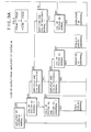
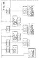
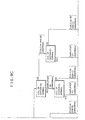
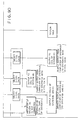
- Then, a flow of selecting I/O to and from the sub-amplifier will be described with reference to Figs. 5A and 5B. First, it is determined whether or not the system A is normal (all of the controller of the system A, the servo amplifier of the system A, the servo position detector of the system A and the coil of the system A are normal). If there is a fault in the system A, a determination is made whether or not the system B is normal. If the system B is abnormal, it can be said that both the systems A and B are abnormal. Therefore, the sub-amplifier
input selection switch 38 is switched over so as to select the output from the normal system C. Therefore, the input to the sub-amplifier is selected when only one system of the systems A, B and C is normal and the residual two systems are abnormal. As a result, a normal value is always input to the sub-amplifier 39, and the output from the sub-amplifier 39 shows a normal value. Then, the output from the sub-amplifier 39 is selected by the amplifieroutput selection switch 40 and the output from the system having the normal coil is selected so as to output it. At this time, if only the system A is normal, a selection of the system having a normal coil is made in a sequential order of B and C. A normal output from the normal system A via the sub-amplifier 39 is transmitted to the servo coil B or C. As a result, an operation similar to a case in which two coils of the three coils are normal is performed by the normal system A and the output servo coil of the system B or C although the systems B and C are abnormal. Therefore, the continuation of the operation of the plant can be enabled. - If a disconnection of the coils B and C are taken place at this time, the sub-amplifier
output selection switch 40 selects the residual normal coil A. The servo coil output from the normal system A and the output from the sub-amplifier selected by the sub-amplifieroutput selection switch 40 are added to the normal coil A. Therefore, its torque is made to be two times the normal torque, causing the response of the one servo coil of the system A to be the same as the operation performed in a case where the two coils act. As a result, although the coils of the systems B and C have been disconnected, only the coil of the normal system A is able to act similarly to the case where the two coils of the three coils are normal. Consequently, the continuation of the operation of the plant can be enabled. - Subsequently, whether or not the systems A, B and C are normal is determined similarly to the above-described case in such a manner that the input of the normal system to the sub-amplifier 39 is selected by the sub-amplifier
input selection switch 38 and the sub-amplifieroutput selection switch 40 so as to output it to the system having the normal servo coil. - The above-described selection is made by the sub-amplifier
input selection switch 38 or the sub-amplifieroutput selection switch 40 in accordance with the flow chart shown in Figs. 5A, 5B and software previously loaded. - The characteristics of the triple-coil servo will now be described with reference to Fig. 6.
- In a case where the servo amplifier A is saturated (tl), the abnormality has been detected in accordance with result of the diagnosis of the feedback value of the electric current of the servo coil performed by the
diagnosis portion 33 of theabnormality detection device 31 of the controller of the system A. The controller A immediately separates the output from the servo amplifier with the output separation switch 35 (t2). Therefore, the influence of the abnormality upon the plant due to the saturation of the servo amplifier of the system A can be reduced in comparison to the conventional case shown in Fig. 3. In a case where the servo amplifier of the system B is saturated in the above-described state, that is, in a case of t3, the controller of the normal system C input its output to the sub-amplifier 39 by thecontroller switch 38. Furthermore, the output from the sub-amplifier 39 is transmitted to the system A, which is a system having the normal servo coil (in this state, although the output may be transmitted to the system A or B, an assumption is made that the output to the system A is made). Therefore, the electric current of the servo coil of the system A compensates the saturated electric current of the system B as well as the electric current of the servo coil of the system C when the servo amplifier of the system B is saturated. As a result, the continuation of the operation can be enabled safely. - In a case where the servo coils of the two systems are disconnected, the output from the sub-amplifier is selected to be output to the servo coil of the residual normal system. As a result, the output with which the torque of the two coils can be obtained from one servo coil is made, causing the continuation of the operation to be enabled.
- Another embodiment will now be described with reference to Fig. 7. This embodiment is arranged in such a manner that the sub-amplifier according to the above-described sub-amplifier is replaced by an
amplifier input switch 41 which selects thecontrol command value 20 of the normal controller. Furthermore, the servo amplifier according to this embodiment is provided with again switch 42 for switching over between the normal gain (gain at the time of one coil) and a two-coil gain which generates the coil electric current, which corresponds to a current generated by two coils, in order to operate the plant by one coil. The servo amplifier is further provided with anamplifier output switch 43 for performing a selection operation to supply the output from the servo amplifier to a normal coil. - The servo amplifier is provided for each of the systems A, B and C. The input at this time is performed in such a manner that the input of the normal controller is selected by the
input switch 41. Then, a flow of the input performed in the amplifier of the system A will now be described with reference to Fig. 8. - The amplifier of the system A selects the controller of the system A. In a case where the controller of the system A is abnormal, determinations whether or not the controller of the system B and that of the system C are sequentially made. As a result, the input of the normal controller is selected by the
amplifier input switch 41. The amplifier of the system B similarly receives thecontrol command value 20 of the normal controller after the determinations about the systems <B>, <C> and <A> have been sequentially made. Also the amplifier of the system C similarly receives thecontrol command value 20 of the normal controller after the determinations about the systems <C>, <A> and <B> have been sequentially made. - As a result, the
control command value 20 of the normal controller is received by each of the servo amplifiers by the action of theswitch 41. - The above-described selections are executed by the action of the
switch 41 in accordance with the flow chart shown in Fig. 8 and software. - Then, the operation of the
gain switch 42 and that of theamplifier output switch 43 will now be described with reference to a flow chart, which illustrate the output from the amplifier of the system A and which is shown in Fig. 9. - In a case where the amplifier of the system A is abnormal, the output from it is separated by the
output separation switch 35. In a case where the above-described amplifier is normal, a determination is made about the status of each of the coils A, B and C and that of the amplifier in order to determine the coil to which the output from the above-described amplifier is supplied. However, in a case where two coils of the three coils A, B and C are abnormal, it is necessary to give the residual coil the torque for the two coils. Therefore, a two-coil gain is selected as the gain at this time. Similarly, theamplifier output switch 43 is operated in order to make the normal amplifier to output in place of the abnormal amplifier in accordance with the status of each of the amplifiers A, B and C. - For example, in a case where the coil of the system A is normal and as well as the coils of the systems B and C are abnormal, the two-coil gain is selected by the
gain switch 42 in order to make the plant to be normally operated by only the coil of the system A. Furthermore, the output to the coil of the system A is made by theoutput switch 43 of the amplifier of the system A. - In a case where both the coils of the systems B and C or either of the same is normal in the above-described state, a 1-coil gain is selected by the
gain switch 42 so that an output to the coil of the system A is made by theamplifier output switch 43. Subsequently, the amplifiers of the systems B and C are operated similarly. - The above-described selection is performed by the
switch 43 in accordance with the flow chart shown in Fig. 9 and software. - Although the control of the triple-coil servo valve is described according to the above-described embodiment, a similar control can be performed in a servo valves having four or more coils by providing a compensation circuit.
- As described above, according to the techniques described the triple-coil servo valve control method having a tripled controller and triple-coil servo valves at the operation end thereof can be arranged so as to obtain outputs from the servo coils which are sufficiently large to operate the plant even if two control systems, for example, the two controllers are abnormal or two servo coils are abnormal.
- Furthermore, turbine control apparatus and a variety of plants which is provided with a triple-coil servo valve control apparatus embodying the concepts described may be able to continue the operation while preventing disturbance. Therefore, availability may besignificantly improved in comparison to the conventional operation method.
- Methods and apparatus as described may be executed simply by adding the above-described compensation apparatus, so rise in the overall cost can be prevented in comparison to the conventional structure while significantly improving the operation performance in comparison to the same.
Claims (8)
- Apparatus for controlling a triple-coil servo valve (6), the servo valve (6) having a control unit comprising triple control systems (A,B,C), the components of each control system includingthe apparatus further comprisinga controller (7,8,9) for outputting a control command signal (20) for controlling a quantity of state of a plant in accordance with a predetermined value,a servo amplifier (21,22,23) for amplifying the control command signal (20) so as to be capable of operating the triple-coil servo valve (6), anda coil (26,27,28) for operating the servo valve (6) to make the quantity of state correspond to the amplified control signal,and wherein in normal operation all three of said coils (26,27,28) operate the servo valve (6) in conjunction with one another;characterised byabnormality detection means (31) for detecting abnormality of a said component of any of the control systems (A,B,C);separation means for disconnecting, in a case where at least one servo amplifier (21,22,23) or controller (7,8,9) is detected as being abnormal, the output of the abnormal servo amplifier or controller from the coil of the corresponding control system (A,B,C) in response to detection of the abnormality; and beingcompensation means, operable in response to the abnormality detection means and including a switch circuit (38,40;41,43) for switching connections between said components of said control systems (A,B,C);the switch circuit being operable to switch a connection between at least one normal component of an abnormal said control system and a normal component of another said control system at least in a case in which abnormal components are detected in two of said control systems,whereby said compensation means is operable(a) when two of said coils (26,27,28) are detected as being abnormal, to adjust the control signal to the residual normal said coil to provide normal operation of the servo valve (6),
and(b) when two of said servo amplifiers (21,22,23) are detected as being abnormal, to connect the residual normal said servo amplifier or a sub-servo amplifier (39) to operate additionally the normal coil (26,27,28) of a said control system (A,B,C) in which the servo amplifier (21,22,23) is abnormal, or to operate a single normal said coil (26,27,28) with an increased control signal. - Fuel flow rate control apparatus including:a triple coil servo valve (6) for a gas turbine (4);an apparatus according to claim 1 for controlling said servo valve (6);a torque motor (29) arranged to be operated by the coils (26,27,28);an actuator (24) arranged to be operated by the torque motor (29); anda fuel flow rate control valve arranged to be opened/closed by the actuator (24);said quantity of state being the degree of opening of the fuel flow rate control valve.
- Apparatus according to claim 1 or 2 in which the compensation means includes a sub-servo amplifier (39) and the switch circuit is operable, in response to detection of abnormality in the servo amplifier (21,22,23) of one of said control systems (A,B,C), to switch the normal controller (7,8,9) of that control system (A,B,C) into connection with the sub-servo amplifier (39) and the sub-servo amplifier (39) into connection with a normal coil of one of said control systems (A,B,C).
- Apparatus according to claim 1 or 2 in which the compensation means includes means (42) for increasing the gain of the servo amplifier (21,22,23) of a residual normal one of the control systems (A,B,C) in response to the detection of abnormality in, and disconnection of, another of the control systems (A,B,C).
- A method of controlling a triple-coil servo valve having triple control systems (A,B,C), the components of each control system (A,B,C) includingthe method further comprising:a controller (7,8,9) for outputting a control command signal (20) for controlling a quantity of state of a plant in accordance with a predetermined value,a servo amplifier (21,22,23) for amplifying the control command signal (20) so as to be capable of operating the triple-coil servo valve (6), anda coil (26,27,28) for operating the servo valve (6) to make a quantity of state correspond to the amplified control signal,and wherein in normal operation all three of said coils (26,27,28) operate the servo valve (6) in conjunction with one another,detecting an abnormality of a said component of any of the control systems (A,B,C);separating, in a case where at least one servo amplifier (21,22,23) or controller (7,8,9) is thus detected as being abnormal, the output of the abnormal servo-amplifier or controller from the coil of the corresponding control system (A,B,C) in response to detection of the abnormality; and being characterised by:compensating, at least in response to detection of an abnormality in two of said control systems, by switching a connection between at least one normal component of an abnormal said control system and a normal component of another said control system; and thereby(a) when two of said coils (26,27,28) are detected as being abnormal, adjusting the control signal to the residual normal said coil to provide normal operation of the servo valve (6),
and(b) when two of said servo amplifiers (21,22,23) are detected as being abnormal, connecting the residual normal said servo amplifier or a sub-servo amplifier (39) to operate additionally the normal coil (26,27,28) of a said control system (A,B,C) in which the servo amplifier (21,22,23) is abnormal, or to operate a single normal said coil (26,27,28) with an increased control signal. - A method according to claim 5, wherein the quantity of state is the degree of opening of a fuel flow rate control valve.
- A method according to claim 5 or claim 6 wherein the compensation includes amplification of one of said control command signals by a said sub-servo amplifier (39).
- A method according to claim 5 or claim 6, wherein the compensation includes amplification of one of said control command signals by changing the gain of a said servo amplifier (21,22,23).
Applications Claiming Priority (3)
| Application Number | Priority Date | Filing Date | Title |
|---|---|---|---|
| JP13480190 | 1990-05-24 | ||
| JP13480190 | 1990-05-24 | ||
| JP134801/90 | 1990-05-24 |
Publications (3)
| Publication Number | Publication Date |
|---|---|
| EP0458639A2 EP0458639A2 (en) | 1991-11-27 |
| EP0458639A3 EP0458639A3 (en) | 1993-06-02 |
| EP0458639B1 true EP0458639B1 (en) | 1999-08-04 |
Family
ID=15136848
Family Applications (1)
| Application Number | Title | Priority Date | Filing Date |
|---|---|---|---|
| EP91304690A Expired - Lifetime EP0458639B1 (en) | 1990-05-24 | 1991-05-23 | Servo valve control method and apparatus |
Country Status (3)
| Country | Link |
|---|---|
| US (1) | US5214913A (en) |
| EP (1) | EP0458639B1 (en) |
| DE (1) | DE69131495T2 (en) |
Families Citing this family (7)
| Publication number | Priority date | Publication date | Assignee | Title |
|---|---|---|---|---|
| US5757641A (en) * | 1995-07-03 | 1998-05-26 | General Electric Company | Triplex control system with sensor failure compensation |
| US6003811A (en) * | 1997-03-24 | 1999-12-21 | The Boeing Company | Aircraft servovalve current rate limiter |
| EP1078729A1 (en) * | 1999-08-25 | 2001-02-28 | Engel Maschinenbau Gesellschaft Mbh | Injection moulding machine with means to detect a sensor failure |
| US6508054B2 (en) * | 2000-05-31 | 2003-01-21 | Hitachi, Ltd. | Control system for servo valve and combined-cycle electric-power generating plant and gas turbine plant |
| GB0120004D0 (en) * | 2001-08-16 | 2001-10-10 | Lucas Industries Ltd | Hydraulic valve arrangement |
| US8698486B2 (en) | 2011-09-16 | 2014-04-15 | General Electric Company | Methods and systems for use in checking the polarity of multi-coil servos |
| CN107561438B (en) * | 2016-06-30 | 2019-11-22 | 江苏核电有限公司 | A method for checking correctness of throttle opening of diesel engine governor |
Family Cites Families (12)
| Publication number | Priority date | Publication date | Assignee | Title |
|---|---|---|---|---|
| US3054039A (en) * | 1957-09-05 | 1962-09-11 | Meredith Dennis Lello | Plural channel servo systems |
| US3469162A (en) * | 1965-04-13 | 1969-09-23 | Hawker Siddeley Dynamics Ltd | Multiplex-type control apparatus |
| US3437312A (en) * | 1966-11-01 | 1969-04-08 | Bell Aerospace Corp | Electrical signal and monitoring apparatus for redundant control system |
| US3875390A (en) * | 1970-07-09 | 1975-04-01 | Secr Defence Brit | On-line computer control system |
| US4105900A (en) * | 1977-02-16 | 1978-08-08 | The Boeing Company | Signal selection apparatus for redundant signal sources |
| US4521707A (en) * | 1983-12-12 | 1985-06-04 | The Boeing Company | Triple redundant electromechanical linear actuator and method |
| US4608820A (en) * | 1985-05-03 | 1986-09-02 | Chandler Evans Inc. | Dual stepper motor actuator for fuel metering valve |
| US4752869A (en) * | 1985-05-09 | 1988-06-21 | Westinghouse Electric Corp. | Auxiliary reactor protection system |
| US4843537A (en) * | 1986-07-04 | 1989-06-27 | Hitachi, Ltd. | Control system |
| DE3637238A1 (en) * | 1986-11-03 | 1988-05-05 | Siemens Ag | DIGITAL 2 OF 3 SELECTION AND OUTPUT SWITCHING |
| JPH0731537B2 (en) * | 1987-09-11 | 1995-04-10 | 株式会社日立製作所 | Multiplex controller |
| DE3825280A1 (en) * | 1988-07-26 | 1990-02-01 | Bayerische Motoren Werke Ag | CONTROL SYSTEM FOR ACTUATING DEVICES OF A MOTOR VEHICLE |
-
1991
- 1991-05-22 US US07/704,139 patent/US5214913A/en not_active Expired - Lifetime
- 1991-05-23 EP EP91304690A patent/EP0458639B1/en not_active Expired - Lifetime
- 1991-05-23 DE DE69131495T patent/DE69131495T2/en not_active Expired - Fee Related
Also Published As
| Publication number | Publication date |
|---|---|
| DE69131495D1 (en) | 1999-09-09 |
| EP0458639A2 (en) | 1991-11-27 |
| EP0458639A3 (en) | 1993-06-02 |
| US5214913A (en) | 1993-06-01 |
| DE69131495T2 (en) | 2000-03-23 |
Similar Documents
| Publication | Publication Date | Title |
|---|---|---|
| US3665809A (en) | Multiple channel redundant control system | |
| US5214913A (en) | Servo valve control apparatus | |
| US4440715A (en) | Method of controlling nuclear power plant | |
| US4664870A (en) | Testable voted logic power interface | |
| JP2003148108A (en) | Servo valve system and its operating method | |
| JP2684866B2 (en) | Servo valve control method | |
| US6616121B2 (en) | Control system for servo valve and control method therefor, and combined-cycle electric-power generating plant and gas turbine plant | |
| US4436018A (en) | Multiple loop control system | |
| JP2008269165A (en) | Multi-coil servo valve controller | |
| US20030123599A1 (en) | Nuclear power plant having steam turbine controller | |
| JPH045201B2 (en) | ||
| JPS6236241B2 (en) | ||
| JP2000018145A (en) | Governor of hydropower plant and method of operating the same | |
| JP2501166B2 (en) | Turbine control equipment for power plants | |
| JP2005105912A (en) | Multi-coil servo valve controller | |
| JP4802834B2 (en) | Servo valve control circuit | |
| WO2022113345A1 (en) | Control switching device | |
| JP2539514B2 (en) | Boiler water supply control device | |
| JP2907930B2 (en) | Nuclear power plant safety protection equipment | |
| JPH10222203A (en) | Digital controller | |
| JPS6213121Y2 (en) | ||
| KR19980024802A (en) | Pump selection logic circuit | |
| JP2730372B2 (en) | Turbine control device | |
| WO2026074850A1 (en) | Fault assessment device, fault assessment method, and program | |
| JPS63140305A (en) | Control protecting device |
Legal Events
| Date | Code | Title | Description |
|---|---|---|---|
| PUAI | Public reference made under article 153(3) epc to a published international application that has entered the european phase |
Free format text: ORIGINAL CODE: 0009012 |
|
| AK | Designated contracting states |
Kind code of ref document: A2 Designated state(s): CH DE FR GB IT LI |
|
| PUAL | Search report despatched |
Free format text: ORIGINAL CODE: 0009013 |
|
| AK | Designated contracting states |
Kind code of ref document: A3 Designated state(s): CH DE FR GB IT LI |
|
| 17P | Request for examination filed |
Effective date: 19930707 |
|
| 17Q | First examination report despatched |
Effective date: 19941227 |
|
| GRAG | Despatch of communication of intention to grant |
Free format text: ORIGINAL CODE: EPIDOS AGRA |
|
| GRAG | Despatch of communication of intention to grant |
Free format text: ORIGINAL CODE: EPIDOS AGRA |
|
| GRAH | Despatch of communication of intention to grant a patent |
Free format text: ORIGINAL CODE: EPIDOS IGRA |
|
| GRAH | Despatch of communication of intention to grant a patent |
Free format text: ORIGINAL CODE: EPIDOS IGRA |
|
| GRAA | (expected) grant |
Free format text: ORIGINAL CODE: 0009210 |
|
| AK | Designated contracting states |
Kind code of ref document: B1 Designated state(s): CH DE FR GB IT LI |
|
| REG | Reference to a national code |
Ref country code: CH Ref legal event code: EP |
|
| REF | Corresponds to: |
Ref document number: 69131495 Country of ref document: DE Date of ref document: 19990909 |
|
| ITF | It: translation for a ep patent filed | ||
| ET | Fr: translation filed | ||
| REG | Reference to a national code |
Ref country code: CH Ref legal event code: NV Representative=s name: TROESCH SCHEIDEGGER WERNER AG |
|
| PLBE | No opposition filed within time limit |
Free format text: ORIGINAL CODE: 0009261 |
|
| STAA | Information on the status of an ep patent application or granted ep patent |
Free format text: STATUS: NO OPPOSITION FILED WITHIN TIME LIMIT |
|
| 26N | No opposition filed | ||
| REG | Reference to a national code |
Ref country code: GB Ref legal event code: IF02 |
|
| PGFP | Annual fee paid to national office [announced via postgrant information from national office to epo] |
Ref country code: CH Payment date: 20080401 Year of fee payment: 18 Ref country code: DE Payment date: 20080606 Year of fee payment: 18 |
|
| PGFP | Annual fee paid to national office [announced via postgrant information from national office to epo] |
Ref country code: IT Payment date: 20080423 Year of fee payment: 18 |
|
| PGFP | Annual fee paid to national office [announced via postgrant information from national office to epo] |
Ref country code: GB Payment date: 20080424 Year of fee payment: 18 |
|
| REG | Reference to a national code |
Ref country code: CH Ref legal event code: PL |
|
| GBPC | Gb: european patent ceased through non-payment of renewal fee |
Effective date: 20090523 |
|
| PG25 | Lapsed in a contracting state [announced via postgrant information from national office to epo] |
Ref country code: CH Free format text: LAPSE BECAUSE OF NON-PAYMENT OF DUE FEES Effective date: 20090531 Ref country code: LI Free format text: LAPSE BECAUSE OF NON-PAYMENT OF DUE FEES Effective date: 20090531 |
|
| REG | Reference to a national code |
Ref country code: FR Ref legal event code: ST Effective date: 20100129 |
|
| PG25 | Lapsed in a contracting state [announced via postgrant information from national office to epo] |
Ref country code: FR Free format text: LAPSE BECAUSE OF NON-PAYMENT OF DUE FEES Effective date: 20090602 |
|
| PGFP | Annual fee paid to national office [announced via postgrant information from national office to epo] |
Ref country code: FR Payment date: 20080423 Year of fee payment: 18 |
|
| PG25 | Lapsed in a contracting state [announced via postgrant information from national office to epo] |
Ref country code: GB Free format text: LAPSE BECAUSE OF NON-PAYMENT OF DUE FEES Effective date: 20090523 |
|
| PG25 | Lapsed in a contracting state [announced via postgrant information from national office to epo] |
Ref country code: DE Free format text: LAPSE BECAUSE OF NON-PAYMENT OF DUE FEES Effective date: 20091201 |
|
| PG25 | Lapsed in a contracting state [announced via postgrant information from national office to epo] |
Ref country code: IT Free format text: LAPSE BECAUSE OF NON-PAYMENT OF DUE FEES Effective date: 20090523 |