EP0458501A2 - Protection of supply metering - Google Patents
Protection of supply metering Download PDFInfo
- Publication number
- EP0458501A2 EP0458501A2 EP91304273A EP91304273A EP0458501A2 EP 0458501 A2 EP0458501 A2 EP 0458501A2 EP 91304273 A EP91304273 A EP 91304273A EP 91304273 A EP91304273 A EP 91304273A EP 0458501 A2 EP0458501 A2 EP 0458501A2
- Authority
- EP
- European Patent Office
- Prior art keywords
- memory
- power
- downs
- crash
- credit
- Prior art date
- Legal status (The legal status is an assumption and is not a legal conclusion. Google has not performed a legal analysis and makes no representation as to the accuracy of the status listed.)
- Granted
Links
Images


Classifications
-
- G—PHYSICS
- G01—MEASURING; TESTING
- G01R—MEASURING ELECTRIC VARIABLES; MEASURING MAGNETIC VARIABLES
- G01R15/00—Details of measuring arrangements of the types provided for in groups G01R17/00 - G01R29/00, G01R33/00 - G01R33/26 or G01R35/00
- G01R15/002—Switches for altering the measuring range or for multitesters
-
- G—PHYSICS
- G06—COMPUTING; CALCULATING OR COUNTING
- G06F—ELECTRIC DIGITAL DATA PROCESSING
- G06F11/00—Error detection; Error correction; Monitoring
-
- G—PHYSICS
- G07—CHECKING-DEVICES
- G07F—COIN-FREED OR LIKE APPARATUS
- G07F15/00—Coin-freed apparatus with meter-controlled dispensing of liquid, gas or electricity
- G07F15/003—Coin-freed apparatus with meter-controlled dispensing of liquid, gas or electricity for electricity
Definitions
- This invention concerns metered supplies for example of electricity and the protection of the metering used to meter the quantities of electricity or other consumables supplied for example to an end user.
- the invention is concerned with the protection of such metering devices against fraudulent interference using local high voltage electrical discharges such as piezo-electric gas lighters and static removing devices as used on record players and the like.
- Electronic circuitry can be seriously affected by high voltage discharges such as produced by piezo electric gas lighters and the like.
- electricity meters and other supply meters such as water supply meters and the like have not incorporated sensitive electronic circuitry.
- sensitive electronic circuitry With the tendency towards more sophisticated metering, remote reading telemetary systems and the like, increasing use is made of sensitive electronic circuitry and if a high voltage discharge occurs in close proximity to such circuitry when the latter is operating, the resulting electrical interference can either cause the circuitry to perform incorrectly and for example switch off or switch on equipment when the reverse condition is in fact required, and in some circumstances may even cause the electronic circuitry to become partially destroyed due to electrical breakdown across sensitive semi-conductor junctions.
- a breakdown may occur whilst the controlled equipment is in one mode or another and should this occur when the controlled equipment is in its ON mode, the result will be that the controlled equipment may not be capable of being isolated or may be rendered inoperative, or in the case of a supply meter, may be left in the ON condition irrespective of whether prepayment has been made or not.
- power failure detection means and signal generating means for generating a particular pattern of signals whenever an orderly shutdown is required, due to failure of a supply, deliberate or otherwise or power-down when a prepaid credit expires non volatile memory means in which the said particular pattern of signals is stored, means for reading the memory contents on subsequent power-up and further signal generating means for generating a control signal if the pattern of signals is not found in the memory thereby to indicate that the previous interruption was not an orderly shutdown.
- crash power-downs Power-downs due to interference as described will be referred to as crash power-downs.
- the control signal so generated may be added to a running total of similar such control signals and electronic comparison may be effected between the running total and a reference value such that when the latter is for example reached or exceeded, an auto-disconnect circuit is activated so as to render the controlled unit (eg valve, switch etc), non-operational.
- a controlled unit eg valve, switch etc
- the controlled unit is a prepayment meter for the supply of a commodity such as electricity
- the electronic circuit means includes memory means within which credit data is stored enabling such commodity to be supplied whilst credit remains
- the auto-disconnect circuit may additionally be organised so as to decrement any credit remaining in the memory so as to render the unit non-operational until a credit is again entered in the memory (as by entering money into a slot or a machine readable prepayment card into a card reader associated therewith, or by a remote signalling system).
- the memory which is employed for storing the said pattern of signals may also store the purchased credit data and the accumulating number of control signals indicating crash power-downs.
- the memory is non volatile memory and is typically an erasable programmable read only memory (EPROM).
- EPROM erasable programmable read only memory
- a battery source or like device may be employed as back-up to ensure that the EPROM (which is basically an active device), is rendered non volatile ie does not lose the contents of its memory in the event of a supply failure.
- the decrementing of credit data stored within the memory may be such as to leave a negative balance within the memory which itself has to be paid off by inserting an appropriate credit (either by way of money or machine readable prepayment credit card or by remote signalling), having sufficient value to pay off not only the negative balance (which for convenience should be displayed) but also to put sufficient credit into the memory to enable the supply of the commodity to be restored.
- an appropriate credit either by way of money or machine readable prepayment credit card or by remote signalling
- the first normal procedure may be as previously described in which any remaining credit in the memory is decremented to zero (or a negative balance) and the apparatus can be restored to its normal operating condition by the insertion of an appropriate credit either by way of cash or machine readable cards prepurchased for the purpose (or by remote signalling), with or without the need to press a reset control or the like.
- the second procedure may involve the permanent shutting down of the apparatus so as to prevent it from being restored to normal operation other than by the services of a skilled operator such as an Electricity Board officer, Water Board officer or the like.
- a running total of all the crash power-downs which occur may be maintained within the memory of the control circuitry and after a predetermined number of such power downs the normal shut-down procedure may be adopted enabling the user to restore the supply of the commodity albeit with a penalty but when the running total reaches a second predetermined number, the second level of shut-down procedure is implemented which is arranged to inhibit the apparatus from further operation and shuts off the supply of the commodity on a semi-permanent basis such that it can only be restored at a later stage.
- crash power-downs can occur for legitimate reasons albeit at relatively infrequent intervals, a further refinement may be incorporated namely the decrementing of the first running total of crash power-downs to zero after specific intervals of time so as to eliminate from the memory the odd spasmodic crash power-down caused by natural interference symptomatic of electrical installations.
- the time periods may be irregular so as to eliminate any element of periodicity.
- the period over which the first running total is allowed to accumulate control signals arising from crash power-downs before decrementing to zero may be influenced by the number of crash power-downs which have accumulated within the preceding period, and control means may be provided which increases the period during which the number of crash count-downs are counted before decrementing to zero, in the event that the number of crash power-downs occurring during the preceding period is greater than that during the period which preceded the said preceding period. In this way over a period of time the apparatus will set its own period over which crash power-downs are counted before resetting, to take account of the number of crash power downs occurring and thereby rendering the apparatus more sensitive to crash power-downs with time.
- the auto disconnect circuit Whilst this may cause the auto disconnect circuit to come into operation on the odd occasion, when the reason is an innocent one, the user will almost certainly contact the Electricity Board or other commodity provider and complain at the time, enabling an officer of the Board to come and visit and check the installation. If however, the reason for the auto disconnect circuit becoming operational is due to fraudulent interference the Board will probably not be advised of the problem and matters will either revert to normal (ie the fraudulent interference will cease) or will continue and the apparatus will continue to become more and more sensitive to fraudulent interference as the length of the period before the preliminary count is decremented to zero is increased, so that there will be an increasing frequency in the operation of the automatic disconnect circuit and recordal of these occurances in the memory within the apparatus so as to provide evidence of the ongoing activity at a later stage.
- the memory means within the apparatus can be addressed and read either by an officer of the Board or business in charge of the apparatus or by remote sensing.
- the memory means continues to record interference with the control electronics as by local electrical discharges even after the auto disconnect circuit has operated so as to lock out the equipment and require the attendance of a Board officer to restore the supply.
- evidence of electrical interference as by high voltage electrical discharges in the proximity of the apparatus, will continue to accumulate within the apparatus at a time when a fraudulent user may in fact be attempting to retrigger the apparatus by causing such discharges to occur.
- the invention provides memory means which contain at any time an accumulating number equal to the total number of crash power-downs which have occurred and this may be used as evidence of attempted interference should it be needed.
- apparatus returned to a test room in a lock out condition with a high crash power-down number will present good evidence of attempted fraud.
- the apparatus could be re-installed after the permanent lock out has been cleared, and left for a period of time in a "clean" environment to demonstrate that crash power-downs do not occur due for example to some fault within the apparatus.
- a central processor stores in an associated non volatile memory such as an EPROM, a pattern of electrical signals whenever an orderly shut down occurs (that is on power down by the Electricity Board or as a result of failure of the supply which is deliberate or otherwise).
- an orderly shut down that is on power down by the Electricity Board or as a result of failure of the supply which is deliberate or otherwise.
- the memory is checked and if the pattern is not there then it is assumed that there must have been a crash such as occurs due to an attack on the equipment arising from a local high voltage electrical discharge as from a gas lighter.
- the initial response to an apparent crash condition is to set a report number within a memory unit (typically the same EPROM), to clear any credit and incur for example one day's worth of fixed charge thereby resulting in disconnction until the unit is brought back into credit by inserting prepayment cards or cash of sufficient value. This has a deterrent effect on any repeated interference.
- the report number in the memory is always saved in non volatile EPROM but the credit/debit may be saved in random access memory.
- the report number is secure even if the credit/debit status data is corrupted in severe attacks which can cause it to come up as a high debit value.
- the credit or debt status is conveniently saved in the form of a pattern of signals which is very vulnerable to electrical interference, and the apparatus is arranged so that if the pattern becomes corrupted due to electrical interference as by a local electrical discharge, then the default condition is arranged to produce a debt rather than a credit.
- the central processor unit is programmed to go into lock out thereby disconnecting the supply with no way out other than by removal of the unit by an engineer for corrective servicing in the laboratory.
- the central processor unit is arranged to continue to record further attacks and to increase the report number up to the maximum capability of the memory.
- the report number count may be cleared periodically such as every 24 hours or longer but the apparatus may nevertheless record permanently the total number of crashes which have occurred so as to provide the necessary evidence in the event that it subsequently becomes obvious that the meter has been interfered with, but in such a way as not to accumulate a sufficient number of crash power-down counts in any period of time to produce a permanent lock out condition.
- the apparatus is shown as including a micro-controller or CPU 10 to which signals from a magnetic read head 12 are supplied, the read head forming part of a card reader into which prepaid credit cards are inserted to enter a credit into the micro-controller memory to enable a commodity to be placed on-line available for use by the user.
- a non volatile EPROM memory 14 is associated with the micro-controller and part of the memory is used for storing data relating to the credit inserted and read by the magnetic read head 12.
- a pattern of data may also be stored in the memory or within the random access memory contained within the central processor 10 and in the event of electrical interference, it is most likely that this pattern will be corrupted.
- Logic circuits (not shown but contained within the microprocessor) determine the status of the pattern and in the event that it has been corrupted indicate immediately that all credit has been used up and that a debit condition exists.
- the credit data stored in the memory may itself be cancelled or left intact depending on the logic.
- the micro-controller 10 operates other devices associated with the read head so as to erase the data on the card after it has been read to prevent the card from being used a second time. These elements are indicated by reference numeral 16.
- a 16 character display unit 18 is also controlled by the central processor unit 10 via suitable drivers which may be incorporated within the central processor unit.
- the LCD module is arranged to display the credit which has been purchased or the debit which exists or any other information which is to be displayed and conveyed to the user.
- Data for driving the LCD module may be stored in the EPROM.
- the central processor unit 10 also serves to operate a contactor 20, which may be in the form of an electric motor which acts on and controls a circuit breaker within the controlled apparatus (not shown) so as to open or close the circuit breaker to enable current to be supplied to the user or otherwise.
- a contactor 20 may be in the form of an electric motor which acts on and controls a circuit breaker within the controlled apparatus (not shown) so as to open or close the circuit breaker to enable current to be supplied to the user or otherwise.
- a pulse counter 22 is responsive to metering pulses supplied by the electricity supply board involved and the count from the pulse counter 22 is supplied to the micro-controller to indicate the usage of electricity. As the increasing pulse count is seen by the micro-controller, so the credit available is decremented until all of the available credit has been exhausted.
- a watch-dog and power detection circuit 24 which detects the event of a power down ie the failure of the supply to the contactor contacts and in that event generates a known pattern of signals which are then stored at the micro-controller in the non volatile EPROM memory 14.
- the micro-controller When power is again restored to the contactor contacts, the micro-controller first reads the non volatile EPROM memory 14 and if the pattern of signals are present, orderly restoration of power is permitted and no record is made of the power down and stored in the non volatile EPROM memory 14.
- the watch-dog power detection circuit 24 causes a record in the form of a report number to be stored in the non volatile EPROM memory and each time this state is determined, this report number is incremented by one and further signals from the watch-dog circuit 24 are utilised to decrement any credit remaining in the non volatile EPROM memory to zero or to a negative value and this is displayed on the LCD module 18 with an invitation for the user to insert a further prepaid credit card to restore the supply.
- FIG. 2 normal running mode is denoted by box 26. If a power loss is noted due to a failure of the electricity supply then orderly shutdown is instructed with the insertion of the known pattern of electrical signals into the non volatile memory 14.
- the normal running mode 26 is interrupted by an invalid interruption such as caused by a localised electrical discharge resulting in a crash signal being generated by the magnetic read head 12.
- the micro-controller is programmed to immediately switch off the contactor 20 to inhibit the supply of power but since the power down has occurred without the removal of power from the contactor contacts, no pattern of signals is stored in the non volatile EPROM memory 14 and an invalid state is noted by the watch-dog circuit 24 as a result of the disorderly shutdown.
- This condition is denoted by box 30 in Figure 3. This causes the watch-dog circuit 24 to be reset (see instruction 32) and causes the report number to be incremented by one in the non volatile EPROM memory 14 when the contactor is enabled and the power is restored.
- Restoration of the power may be as a result of an automatic countdown procedure by the micro-controller which will attempt to close the contactor after an interference discharge of this nature or a reset button may be provided on the apparatus which has to be pressed by the user to instigate the power up mode.
- boot up or power up instruction is denoted by reference numeral 34.
- the non volatile EPROM memory 14 is consulted to determine if the previous shut down was orderly or disorderly to instigate normal running or envoking customer penalty before normal running mode can be instigated as in Figure 5.
Abstract
Description
- This invention concerns metered supplies for example of electricity and the protection of the metering used to meter the quantities of electricity or other consumables supplied for example to an end user. In particular the invention is concerned with the protection of such metering devices against fraudulent interference using local high voltage electrical discharges such as piezo-electric gas lighters and static removing devices as used on record players and the like.
- Electronic circuitry can be seriously affected by high voltage discharges such as produced by piezo electric gas lighters and the like. Historically electricity meters and other supply meters such as water supply meters and the like have not incorporated sensitive electronic circuitry. With the tendency towards more sophisticated metering, remote reading telemetary systems and the like, increasing use is made of sensitive electronic circuitry and if a high voltage discharge occurs in close proximity to such circuitry when the latter is operating, the resulting electrical interference can either cause the circuitry to perform incorrectly and for example switch off or switch on equipment when the reverse condition is in fact required, and in some circumstances may even cause the electronic circuitry to become partially destroyed due to electrical breakdown across sensitive semi-conductor junctions. A breakdown may occur whilst the controlled equipment is in one mode or another and should this occur when the controlled equipment is in its ON mode, the result will be that the controlled equipment may not be capable of being isolated or may be rendered inoperative, or in the case of a supply meter, may be left in the ON condition irrespective of whether prepayment has been made or not.
- Unfortunately in practice electrical interference such as caused by lightning or other electrical equipment in proximity with or connected to the equipment containing the sensitive circuitry may also cause similar interference. It is in general impossible to distinguish between one electrical discharge and another which are sufficient to cause interference with sensitive electronic circuits, and clearly the detection of innocent or accidental interference should not penalise a domestic user or other person by, for example, terminating the supply on a semi-permanent basis in the event of any such discharge being detected. The present invention therefore not only deals with the problem of detecting and acting on local electrical interference but also seeks to indicate whether such interference is fraudulent.
- According to the present invention in association with electronic circuitry which controls the operation of a valve or switch to in turn control the supply of a commodity such as electric current and which can be affected by high voltage discharges, there is provided power failure detection means and signal generating means for generating a particular pattern of signals whenever an orderly shutdown is required, due to failure of a supply, deliberate or otherwise or power-down when a prepaid credit expires non volatile memory means in which the said particular pattern of signals is stored, means for reading the memory contents on subsequent power-up and further signal generating means for generating a control signal if the pattern of signals is not found in the memory thereby to indicate that the previous interruption was not an orderly shutdown.
- Power-downs due to interference as described will be referred to as crash power-downs.
- The control signal so generated may be added to a running total of similar such control signals and electronic comparison may be effected between the running total and a reference value such that when the latter is for example reached or exceeded, an auto-disconnect circuit is activated so as to render the controlled unit (eg valve, switch etc), non-operational.
- According to a preferred feature of the invention, where the controlled unit is a prepayment meter for the supply of a commodity such as electricity, and the electronic circuit means includes memory means within which credit data is stored enabling such commodity to be supplied whilst credit remains, the auto-disconnect circuit may additionally be organised so as to decrement any credit remaining in the memory so as to render the unit non-operational until a credit is again entered in the memory (as by entering money into a slot or a machine readable prepayment card into a card reader associated therewith, or by a remote signalling system).
- The memory which is employed for storing the said pattern of signals, may also store the purchased credit data and the accumulating number of control signals indicating crash power-downs. Preferably the memory is non volatile memory and is typically an erasable programmable read only memory (EPROM). A battery source or like device may be employed as back-up to ensure that the EPROM (which is basically an active device), is rendered non volatile ie does not lose the contents of its memory in the event of a supply failure.
- As a further deterrent to interference, the decrementing of credit data stored within the memory may be such as to leave a negative balance within the memory which itself has to be paid off by inserting an appropriate credit (either by way of money or machine readable prepayment credit card or by remote signalling), having sufficient value to pay off not only the negative balance (which for convenience should be displayed) but also to put sufficient credit into the memory to enable the supply of the commodity to be restored.
- Conveniently two shut-down procedures may be provided following the detection of an crash power-down. The first normal procedure may be as previously described in which any remaining credit in the memory is decremented to zero (or a negative balance) and the apparatus can be restored to its normal operating condition by the insertion of an appropriate credit either by way of cash or machine readable cards prepurchased for the purpose (or by remote signalling), with or without the need to press a reset control or the like. The second procedure may involve the permanent shutting down of the apparatus so as to prevent it from being restored to normal operation other than by the services of a skilled operator such as an Electricity Board officer, Water Board officer or the like. To this end a running total of all the crash power-downs which occur may be maintained within the memory of the control circuitry and after a predetermined number of such power downs the normal shut-down procedure may be adopted enabling the user to restore the supply of the commodity albeit with a penalty but when the running total reaches a second predetermined number, the second level of shut-down procedure is implemented which is arranged to inhibit the apparatus from further operation and shuts off the supply of the commodity on a semi-permanent basis such that it can only be restored at a later stage.
- Since crash power-downs can occur for legitimate reasons albeit at relatively infrequent intervals, a further refinement may be incorporated namely the decrementing of the first running total of crash power-downs to zero after specific intervals of time so as to eliminate from the memory the odd spasmodic crash power-down caused by natural interference symptomatic of electrical installations. The time periods may be irregular so as to eliminate any element of periodicity.
- As a further refinement the period over which the first running total is allowed to accumulate control signals arising from crash power-downs before decrementing to zero may be influenced by the number of crash power-downs which have accumulated within the preceding period, and control means may be provided which increases the period during which the number of crash count-downs are counted before decrementing to zero, in the event that the number of crash power-downs occurring during the preceding period is greater than that during the period which preceded the said preceding period. In this way over a period of time the apparatus will set its own period over which crash power-downs are counted before resetting, to take account of the number of crash power downs occurring and thereby rendering the apparatus more sensitive to crash power-downs with time. Whilst this may cause the auto disconnect circuit to come into operation on the odd occasion, when the reason is an innocent one, the user will almost certainly contact the Electricity Board or other commodity provider and complain at the time, enabling an officer of the Board to come and visit and check the installation. If however, the reason for the auto disconnect circuit becoming operational is due to fraudulent interference the Board will probably not be advised of the problem and matters will either revert to normal (ie the fraudulent interference will cease) or will continue and the apparatus will continue to become more and more sensitive to fraudulent interference as the length of the period before the preliminary count is decremented to zero is increased, so that there will be an increasing frequency in the operation of the automatic disconnect circuit and recordal of these occurances in the memory within the apparatus so as to provide evidence of the ongoing activity at a later stage.
- Conveniently the memory means within the apparatus can be addressed and read either by an officer of the Board or business in charge of the apparatus or by remote sensing.
- Preferably the memory means continues to record interference with the control electronics as by local electrical discharges even after the auto disconnect circuit has operated so as to lock out the equipment and require the attendance of a Board officer to restore the supply. In this way evidence of electrical interference as by high voltage electrical discharges in the proximity of the apparatus, will continue to accumulate within the apparatus at a time when a fraudulent user may in fact be attempting to retrigger the apparatus by causing such discharges to occur.
- The invention provides memory means which contain at any time an accumulating number equal to the total number of crash power-downs which have occurred and this may be used as evidence of attempted interference should it be needed. Thus apparatus returned to a test room in a lock out condition with a high crash power-down number will present good evidence of attempted fraud. If appropriate, the apparatus could be re-installed after the permanent lock out has been cleared, and left for a period of time in a "clean" environment to demonstrate that crash power-downs do not occur due for example to some fault within the apparatus.
- In one embodiment of the invention, a central processor stores in an associated non volatile memory such as an EPROM, a pattern of electrical signals whenever an orderly shut down occurs (that is on power down by the Electricity Board or as a result of failure of the supply which is deliberate or otherwise). On power up, the memory is checked and if the pattern is not there then it is assumed that there must have been a crash such as occurs due to an attack on the equipment arising from a local high voltage electrical discharge as from a gas lighter.
- The initial response to an apparent crash condition is to set a report number within a memory unit (typically the same EPROM), to clear any credit and incur for example one day's worth of fixed charge thereby resulting in disconnction until the unit is brought back into credit by inserting prepayment cards or cash of sufficient value. This has a deterrent effect on any repeated interference.
- Any subsequent interference using a local electrical discharge will cause a repeat of the above sequence of events with an increase in the debt and the report number.
- Conveniently the report number in the memory is always saved in non volatile EPROM but the credit/debit may be saved in random access memory. The report number is secure even if the credit/debit status data is corrupted in severe attacks which can cause it to come up as a high debit value.
- The credit or debt status is conveniently saved in the form of a pattern of signals which is very vulnerable to electrical interference, and the apparatus is arranged so that if the pattern becomes corrupted due to electrical interference as by a local electrical discharge, then the default condition is arranged to produce a debt rather than a credit.
- In the example being described, after for example the fourth crash power-down the central processor unit is programmed to go into lock out thereby disconnecting the supply with no way out other than by removal of the unit by an engineer for corrective servicing in the laboratory. However, even after lock out, the central processor unit is arranged to continue to record further attacks and to increase the report number up to the maximum capability of the memory.
- As previously discussed, since it is impossible to guarantee that over a period of months or years spasmodic crashes will not occur through non fraudulent causes, the report number count may be cleared periodically such as every 24 hours or longer but the apparatus may nevertheless record permanently the total number of crashes which have occurred so as to provide the necessary evidence in the event that it subsequently becomes obvious that the meter has been interfered with, but in such a way as not to accumulate a sufficient number of crash power-down counts in any period of time to produce a permanent lock out condition.
- The invention will now be described by way of example, with reference to the accompanying drawings in which:
- Figure 1 is a block circuit diagram of a card reading commodity metering system;
- Figure 2 shows the steps of a valid power down;
- Figure 3 shows the steps of an invalid power down brought about perhaps by a localised electrical discharge;
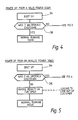
- Figure 4 shows the sequence of events during power up following a valid power down; and
- Figure 5 shows the sequence of events when power up occurs following an invalid power down.
- Detailed description of the drawings
- In Figure 1 the apparatus is shown as including a micro-controller or
CPU 10 to which signals from amagnetic read head 12 are supplied, the read head forming part of a card reader into which prepaid credit cards are inserted to enter a credit into the micro-controller memory to enable a commodity to be placed on-line available for use by the user. A nonvolatile EPROM memory 14 is associated with the micro-controller and part of the memory is used for storing data relating to the credit inserted and read by themagnetic read head 12. In addition to the numerical data indicating the number of units of the commodity which has been purchased, a pattern of data may also be stored in the memory or within the random access memory contained within thecentral processor 10 and in the event of electrical interference, it is most likely that this pattern will be corrupted. Logic circuits (not shown but contained within the microprocessor) determine the status of the pattern and in the event that it has been corrupted indicate immediately that all credit has been used up and that a debit condition exists. The credit data stored in the memory (either in the RAM or the EPROM 14) may itself be cancelled or left intact depending on the logic. - The micro-controller 10 operates other devices associated with the read head so as to erase the data on the card after it has been read to prevent the card from being used a second time. These elements are indicated by
reference numeral 16. - A 16
character display unit 18 is also controlled by thecentral processor unit 10 via suitable drivers which may be incorporated within the central processor unit. The LCD module is arranged to display the credit which has been purchased or the debit which exists or any other information which is to be displayed and conveyed to the user. - Data for driving the LCD module may be stored in the EPROM.
- The
central processor unit 10 also serves to operate acontactor 20, which may be in the form of an electric motor which acts on and controls a circuit breaker within the controlled apparatus (not shown) so as to open or close the circuit breaker to enable current to be supplied to the user or otherwise. - A
pulse counter 22 is responsive to metering pulses supplied by the electricity supply board involved and the count from thepulse counter 22 is supplied to the micro-controller to indicate the usage of electricity. As the increasing pulse count is seen by the micro-controller, so the credit available is decremented until all of the available credit has been exhausted. - In accordance with the invention a watch-dog and
power detection circuit 24 is provided which detects the event of a power down ie the failure of the supply to the contactor contacts and in that event generates a known pattern of signals which are then stored at the micro-controller in the nonvolatile EPROM memory 14. When power is again restored to the contactor contacts, the micro-controller first reads the nonvolatile EPROM memory 14 and if the pattern of signals are present, orderly restoration of power is permitted and no record is made of the power down and stored in the nonvolatile EPROM memory 14. - If however, the regular pattern of signals is not found in the non volatile memory on power up, the watch-dog
power detection circuit 24 causes a record in the form of a report number to be stored in the non volatile EPROM memory and each time this state is determined, this report number is incremented by one and further signals from the watch-dog circuit 24 are utilised to decrement any credit remaining in the non volatile EPROM memory to zero or to a negative value and this is displayed on theLCD module 18 with an invitation for the user to insert a further prepaid credit card to restore the supply. - The mode of operation is best shown in Figures 2 to 5. In Figure 2 normal running mode is denoted by
box 26. If a power loss is noted due to a failure of the electricity supply then orderly shutdown is instructed with the insertion of the known pattern of electrical signals into the nonvolatile memory 14. In Figure 3 thenormal running mode 26 is interrupted by an invalid interruption such as caused by a localised electrical discharge resulting in a crash signal being generated by themagnetic read head 12. The micro-controller is programmed to immediately switch off thecontactor 20 to inhibit the supply of power but since the power down has occurred without the removal of power from the contactor contacts, no pattern of signals is stored in the nonvolatile EPROM memory 14 and an invalid state is noted by the watch-dog circuit 24 as a result of the disorderly shutdown. This condition is denoted bybox 30 in Figure 3. This causes the watch-dog circuit 24 to be reset (see instruction 32) and causes the report number to be incremented by one in the nonvolatile EPROM memory 14 when the contactor is enabled and the power is restored. - Restoration of the power may be as a result of an automatic countdown procedure by the micro-controller which will attempt to close the contactor after an interference discharge of this nature or a reset button may be provided on the apparatus which has to be pressed by the user to instigate the power up mode.
- Following power down, the power up sequences are illustrated in Figures 4 and 5 following the two possible events.
- Thus in Figure 4 the boot up or power up instruction is denoted by
reference numeral 34. The nonvolatile EPROM memory 14 is consulted to determine if the previous shut down was orderly or disorderly to instigate normal running or envoking customer penalty before normal running mode can be instigated as in Figure 5.
Claims (10)
- Protection apparatus for use in combination with electronic circuitry which controls the operation of a controller to in turn control the supply of a commodity and which can be interfered with by high voltage discharges, said apparatus comprising power failure detection means and signal generating means for generating a particular pattern of signals whenever an orderly shutdown is required due to failure of a supply (deliberate or otherwise) or due to power-down when a prepaid credit expires, non volatile memory means in which the said particular pattern of signals is stored, means for reading the memory contents on subsequent power-up and further signal generating means for generating a control signal if the pattern of signals is not found in the memory, thereby to indicate that the previous interruption was not an orderly shutdown but a crash power-down due to interference.
- Apparatus according to claim 1, including means whereby the control signal is added to a running total of similar such control signals and electronic comparison is effected between the running total and a reference value such that when the reference value is obtained, an auto-disconnect circuit is activated so as to render the controller non-operational.
- Apparatus according to claim 2, wherein the controller is a prepayment meter for the supply of a commodity, and the associated electronic circuity includes memory means within which credit data is stored to enable such commodity to be supplied whilst credit remains, and wherein the auto-disconnect circuit is arranged to decrement any credit remaining in the memory so as to render the unit non-operational until a credit is again entered in the memory.
- Apparatus according to claim 1 or claim 2 or claim 3, wherein the memory which is employed for storing the said pattern of signals also stores the accumulatinng number of control signals indicating crash power-downs.
- Apparatus according to claim 4 when apparent to claim 3, wherein, dependent on the stored number of power crash-down, two shut-down procedures are provided following the detection of an crash power-down, namely a first normal procedure in which any remaining credit in the memory is decremented and the controller can be returned to its normal operating condition by the restoration of an appropriate credit, and a second procedure which involves the permanent shutting down of the controller so as to prevent it from being restored to normal operation by the user.
- Apparatus according to claim 5, in which the memory stores a first running total of crash power-downs (contral signals) and when such total reaches a predetermined number the normal shut-down procedure is adopted enabling the user to restore the supply of the commodity albeit with a penalty, and the memory also stores a second running total of crash power-downs whereby, when the second running total reaches a second predetermined number, the second shut-down procedure is implemented which is arranged to inhibit the controller from further operation and shuts off the supply of the commodity on a semi-permanent basis.
- Apparatus according to claim 6, including reasons for decrementing the first running total of crash power-downs to zero after specific periods of time so as to eliminate from the memory any spasmodic crash power-downs caused by natural interference symptomatic of electrical installations.
- Apparatus according to claim 7, including means whereby, the period over which the first running total is allowed to accumulate control signals arising from crash power-downs before decrementing to zero is influenced by the number of crash power-downs which have accumulated within the preceding period, and control means is provided which increases the period during which the number of crash count-downs are counted before decrementing to zero, in the event that the number of crash power-downs occurring during the preceding period is greater than that during the period which preceded the said preceding period.
- Apparatus according to any of claims 6 to 8, wherein the memory means within the apparatus can be addressed by remote sensing.
- Apparatus according to any of claims 6 to 9, wherein the memory means continues to record crash power-downs after the auto disconnect circuit has operated so as to lock out the equipment.
Applications Claiming Priority (2)
| Application Number | Priority Date | Filing Date | Title |
|---|---|---|---|
| GB909011531A GB9011531D0 (en) | 1990-05-23 | 1990-05-23 | Protection of supply metering |
| GB9011531 | 1990-05-23 |
Publications (3)
| Publication Number | Publication Date |
|---|---|
| EP0458501A2 true EP0458501A2 (en) | 1991-11-27 |
| EP0458501A3 EP0458501A3 (en) | 1992-08-12 |
| EP0458501B1 EP0458501B1 (en) | 1995-03-29 |
Family
ID=10676424
Family Applications (1)
| Application Number | Title | Priority Date | Filing Date |
|---|---|---|---|
| EP91304273A Expired - Lifetime EP0458501B1 (en) | 1990-05-23 | 1991-05-13 | Protection of supply metering |
Country Status (8)
| Country | Link |
|---|---|
| US (1) | US5200646A (en) |
| EP (1) | EP0458501B1 (en) |
| AT (1) | ATE120553T1 (en) |
| AU (1) | AU646254B2 (en) |
| DE (1) | DE69108447T2 (en) |
| DK (1) | DK0458501T3 (en) |
| ES (1) | ES2071918T3 (en) |
| GB (2) | GB9011531D0 (en) |
Cited By (2)
| Publication number | Priority date | Publication date | Assignee | Title |
|---|---|---|---|---|
| AP322A (en) * | 1991-05-13 | 1994-03-06 | Tellumat Pty Limited | System for the provision of a reticulated utility. |
| FR2746941A1 (en) * | 1996-03-29 | 1997-10-03 | Schneider Electric Sa | Energy pre-payment control system with automatic test facility |
Families Citing this family (5)
| Publication number | Priority date | Publication date | Assignee | Title |
|---|---|---|---|---|
| GB9210857D0 (en) * | 1992-05-21 | 1992-07-08 | Siemens Measurement Limited | Improvements in or relating to commodity supply meters |
| US5399926A (en) * | 1993-12-30 | 1995-03-21 | Honeywell Inc. | Connected processing systems including mutual power off and signal path disconnect detection |
| JPH0922385A (en) * | 1995-07-05 | 1997-01-21 | Rohm Co Ltd | Data security device and method |
| GB2302952A (en) * | 1995-07-06 | 1997-02-05 | C & C Technology Enterprises | Electrical power consumption control and evaluation system |
| EP2515082A1 (en) * | 2011-04-18 | 2012-10-24 | Nagravision S.A. | System and method to enforce utility meter security |
Citations (4)
| Publication number | Priority date | Publication date | Assignee | Title |
|---|---|---|---|---|
| US4301444A (en) * | 1979-10-19 | 1981-11-17 | Motorola, Inc. | Apparatus for detecting possible defeat of systems for remote metering of utilities |
| US4337466A (en) * | 1980-09-02 | 1982-06-29 | Bell Telephone Laboratories, Incorporated | Tamper protection for an automatic remote meter reading unit |
| US4575801A (en) * | 1983-04-29 | 1986-03-11 | Grh Electronics, Inc. | Submetering apparatus |
| WO1988004433A1 (en) * | 1986-12-08 | 1988-06-16 | Sloan Joseph W | Prepayment metering system using encoded purchase cards |
Family Cites Families (3)
| Publication number | Priority date | Publication date | Assignee | Title |
|---|---|---|---|---|
| US4072852A (en) * | 1976-08-23 | 1978-02-07 | Honeywell Inc. | Digital computer monitoring and restart circuit |
| US4752030A (en) * | 1987-04-22 | 1988-06-21 | Witt Paul L | Mailbox indicator |
| GB8828553D0 (en) * | 1988-12-07 | 1989-01-11 | Mutch A J | Electrical fault detecting device |
-
1990
- 1990-05-23 GB GB909011531A patent/GB9011531D0/en active Pending
-
1991
- 1991-05-13 EP EP91304273A patent/EP0458501B1/en not_active Expired - Lifetime
- 1991-05-13 ES ES91304273T patent/ES2071918T3/en not_active Expired - Lifetime
- 1991-05-13 DE DE69108447T patent/DE69108447T2/en not_active Expired - Fee Related
- 1991-05-13 GB GB9110284A patent/GB2245372B/en not_active Expired - Fee Related
- 1991-05-13 DK DK91304273.5T patent/DK0458501T3/en active
- 1991-05-13 AT AT91304273T patent/ATE120553T1/en not_active IP Right Cessation
- 1991-05-15 US US07/700,594 patent/US5200646A/en not_active Expired - Fee Related
- 1991-05-17 AU AU77114/91A patent/AU646254B2/en not_active Ceased
Patent Citations (4)
| Publication number | Priority date | Publication date | Assignee | Title |
|---|---|---|---|---|
| US4301444A (en) * | 1979-10-19 | 1981-11-17 | Motorola, Inc. | Apparatus for detecting possible defeat of systems for remote metering of utilities |
| US4337466A (en) * | 1980-09-02 | 1982-06-29 | Bell Telephone Laboratories, Incorporated | Tamper protection for an automatic remote meter reading unit |
| US4575801A (en) * | 1983-04-29 | 1986-03-11 | Grh Electronics, Inc. | Submetering apparatus |
| WO1988004433A1 (en) * | 1986-12-08 | 1988-06-16 | Sloan Joseph W | Prepayment metering system using encoded purchase cards |
Cited By (2)
| Publication number | Priority date | Publication date | Assignee | Title |
|---|---|---|---|---|
| AP322A (en) * | 1991-05-13 | 1994-03-06 | Tellumat Pty Limited | System for the provision of a reticulated utility. |
| FR2746941A1 (en) * | 1996-03-29 | 1997-10-03 | Schneider Electric Sa | Energy pre-payment control system with automatic test facility |
Also Published As
| Publication number | Publication date |
|---|---|
| EP0458501B1 (en) | 1995-03-29 |
| AU646254B2 (en) | 1994-02-17 |
| DE69108447D1 (en) | 1995-05-04 |
| US5200646A (en) | 1993-04-06 |
| GB9011531D0 (en) | 1990-07-11 |
| GB2245372A (en) | 1992-01-02 |
| EP0458501A3 (en) | 1992-08-12 |
| AU7711491A (en) | 1991-11-28 |
| ES2071918T3 (en) | 1995-07-01 |
| GB2245372B (en) | 1993-10-27 |
| DK0458501T3 (en) | 1995-07-24 |
| DE69108447T2 (en) | 1995-08-10 |
| ATE120553T1 (en) | 1995-04-15 |
| GB9110284D0 (en) | 1991-07-03 |
Similar Documents
| Publication | Publication Date | Title |
|---|---|---|
| JP3577328B2 (en) | Gaming device | |
| US6111522A (en) | Multiple electronic purse parking meter | |
| US6232886B1 (en) | Method and apparatus for indicating meter tampering | |
| CA1239024A (en) | Programmable service reminder apparatus and method | |
| US4795893A (en) | Security device prohibiting the function of an electronic data processing unit after a first cutoff of its electrical power | |
| US4783801A (en) | Apparatus for protecting secret information | |
| US5003520A (en) | Time accounting system, in particular for parking subject to charge | |
| US7287169B2 (en) | Electronic device and timer therefor with tamper event stamp features and related methods | |
| US5200646A (en) | Protection of supply metering | |
| CA1180120A (en) | Electronic postage meter with weak memory indication | |
| EP2919210A1 (en) | Protection method for data information about electronic device and protection circuit therefor | |
| EP0099571B1 (en) | Housing for electronic device such as a postage meter | |
| US6591251B1 (en) | Method, apparatus, and code for maintaining secure postage data | |
| JPH11505055A (en) | Security protection method for security module and related security module | |
| US5311450A (en) | System and method of detecting authorized dismantlement of transaction machines | |
| EP1939816A1 (en) | Method for detecting the removal of a processing unit from a printed circuit board | |
| EP0131331B1 (en) | Commodity dispensing apparatus | |
| US20010010331A1 (en) | Process for protecting a security module, and associated security module | |
| US20020049683A1 (en) | Process for preventing frauds with regard to a taxi equipped with an electronic taximeter | |
| GB2267156A (en) | Detecting tampering in commodity supply meters | |
| CN218585410U (en) | Anti-dismantling detection circuit, POS equipment and financial transaction system | |
| US5446668A (en) | Franking machine | |
| CN2265541Y (en) | Single phase multi-function automatic IC card electric meter | |
| JP2000040037A (en) | Data protective device, data protective method and storage medium | |
| US20050165675A1 (en) | Settlement terminal |
Legal Events
| Date | Code | Title | Description |
|---|---|---|---|
| PUAI | Public reference made under article 153(3) epc to a published international application that has entered the european phase |
Free format text: ORIGINAL CODE: 0009012 |
|
| AK | Designated contracting states |
Kind code of ref document: A2 Designated state(s): AT BE CH DE DK ES FR GR IT LI LU NL SE |
|
| PUAL | Search report despatched |
Free format text: ORIGINAL CODE: 0009013 |
|
| AK | Designated contracting states |
Kind code of ref document: A3 Designated state(s): AT BE CH DE DK ES FR GR IT LI LU NL SE |
|
| 17P | Request for examination filed |
Effective date: 19920731 |
|
| 17Q | First examination report despatched |
Effective date: 19940214 |
|
| GRAA | (expected) grant |
Free format text: ORIGINAL CODE: 0009210 |
|
| AK | Designated contracting states |
Kind code of ref document: B1 Designated state(s): AT BE CH DE DK ES FR GR IT LI LU NL SE |
|
| REF | Corresponds to: |
Ref document number: 120553 Country of ref document: AT Date of ref document: 19950415 Kind code of ref document: T |
|
| ITF | It: translation for a ep patent filed |
Owner name: STUDIO INGG. FISCHETTI & WEBER |
|
| REF | Corresponds to: |
Ref document number: 69108447 Country of ref document: DE Date of ref document: 19950504 |
|
| ET | Fr: translation filed | ||
| REG | Reference to a national code |
Ref country code: ES Ref legal event code: FG2A Ref document number: 2071918 Country of ref document: ES Kind code of ref document: T3 |
|
| REG | Reference to a national code |
Ref country code: DK Ref legal event code: T3 |
|
| REG | Reference to a national code |
Ref country code: GR Ref legal event code: FG4A Free format text: 3016323 |
|
| PLBE | No opposition filed within time limit |
Free format text: ORIGINAL CODE: 0009261 |
|
| STAA | Information on the status of an ep patent application or granted ep patent |
Free format text: STATUS: NO OPPOSITION FILED WITHIN TIME LIMIT |
|
| 26N | No opposition filed | ||
| PGFP | Annual fee paid to national office [announced via postgrant information from national office to epo] |
Ref country code: GR Payment date: 19970424 Year of fee payment: 7 Ref country code: FR Payment date: 19970424 Year of fee payment: 7 |
|
| PGFP | Annual fee paid to national office [announced via postgrant information from national office to epo] |
Ref country code: AT Payment date: 19970514 Year of fee payment: 7 |
|
| PGFP | Annual fee paid to national office [announced via postgrant information from national office to epo] |
Ref country code: ES Payment date: 19970519 Year of fee payment: 7 |
|
| PGFP | Annual fee paid to national office [announced via postgrant information from national office to epo] |
Ref country code: SE Payment date: 19970520 Year of fee payment: 7 |
|
| PGFP | Annual fee paid to national office [announced via postgrant information from national office to epo] |
Ref country code: DE Payment date: 19970522 Year of fee payment: 7 |
|
| PGFP | Annual fee paid to national office [announced via postgrant information from national office to epo] |
Ref country code: DK Payment date: 19970527 Year of fee payment: 7 |
|
| PGFP | Annual fee paid to national office [announced via postgrant information from national office to epo] |
Ref country code: CH Payment date: 19970529 Year of fee payment: 7 |
|
| PGFP | Annual fee paid to national office [announced via postgrant information from national office to epo] |
Ref country code: NL Payment date: 19970530 Year of fee payment: 7 |
|
| PGFP | Annual fee paid to national office [announced via postgrant information from national office to epo] |
Ref country code: BE Payment date: 19970620 Year of fee payment: 7 |
|
| PGFP | Annual fee paid to national office [announced via postgrant information from national office to epo] |
Ref country code: LU Payment date: 19970908 Year of fee payment: 7 |
|
| PG25 | Lapsed in a contracting state [announced via postgrant information from national office to epo] |
Ref country code: LU Free format text: LAPSE BECAUSE OF NON-PAYMENT OF DUE FEES Effective date: 19980513 Ref country code: AT Free format text: LAPSE BECAUSE OF NON-PAYMENT OF DUE FEES Effective date: 19980513 |
|
| PG25 | Lapsed in a contracting state [announced via postgrant information from national office to epo] |
Ref country code: SE Free format text: LAPSE BECAUSE OF NON-PAYMENT OF DUE FEES Effective date: 19980514 Ref country code: ES Free format text: LAPSE BECAUSE OF NON-PAYMENT OF DUE FEES Effective date: 19980514 |
|
| PG25 | Lapsed in a contracting state [announced via postgrant information from national office to epo] |
Ref country code: LI Free format text: LAPSE BECAUSE OF NON-PAYMENT OF DUE FEES Effective date: 19980531 Ref country code: GR Free format text: LAPSE BECAUSE OF NON-PAYMENT OF DUE FEES Effective date: 19980531 Ref country code: FR Free format text: LAPSE BECAUSE OF NON-PAYMENT OF DUE FEES Effective date: 19980531 Ref country code: DK Free format text: LAPSE BECAUSE OF NON-PAYMENT OF DUE FEES Effective date: 19980531 Ref country code: CH Free format text: LAPSE BECAUSE OF NON-PAYMENT OF DUE FEES Effective date: 19980531 Ref country code: BE Free format text: LAPSE BECAUSE OF NON-PAYMENT OF DUE FEES Effective date: 19980531 |
|
| BERE | Be: lapsed |
Owner name: AMPY AUTOMATION - DIGILOG LTD Effective date: 19980531 |
|
| PG25 | Lapsed in a contracting state [announced via postgrant information from national office to epo] |
Ref country code: NL Free format text: LAPSE BECAUSE OF NON-PAYMENT OF DUE FEES Effective date: 19981201 |
|
| REG | Reference to a national code |
Ref country code: CH Ref legal event code: PL |
|
| EUG | Se: european patent has lapsed |
Ref document number: 91304273.5 |
|
| NLV4 | Nl: lapsed or anulled due to non-payment of the annual fee |
Effective date: 19981201 |
|
| PG25 | Lapsed in a contracting state [announced via postgrant information from national office to epo] |
Ref country code: DE Free format text: LAPSE BECAUSE OF NON-PAYMENT OF DUE FEES Effective date: 19990302 |
|
| REG | Reference to a national code |
Ref country code: FR Ref legal event code: ST |
|
| REG | Reference to a national code |
Ref country code: DK Ref legal event code: EBP |
|
| REG | Reference to a national code |
Ref country code: ES Ref legal event code: FD2A Effective date: 20000403 |
|
| PG25 | Lapsed in a contracting state [announced via postgrant information from national office to epo] |
Ref country code: IT Free format text: LAPSE BECAUSE OF NON-PAYMENT OF DUE FEES;WARNING: LAPSES OF ITALIAN PATENTS WITH EFFECTIVE DATE BEFORE 2007 MAY HAVE OCCURRED AT ANY TIME BEFORE 2007. THE CORRECT EFFECTIVE DATE MAY BE DIFFERENT FROM THE ONE RECORDED. Effective date: 20050513 |