EP0458434A2 - Rotary cutter with Diamond-like cutting edges - Google Patents
Rotary cutter with Diamond-like cutting edges Download PDFInfo
- Publication number
- EP0458434A2 EP0458434A2 EP91301141A EP91301141A EP0458434A2 EP 0458434 A2 EP0458434 A2 EP 0458434A2 EP 91301141 A EP91301141 A EP 91301141A EP 91301141 A EP91301141 A EP 91301141A EP 0458434 A2 EP0458434 A2 EP 0458434A2
- Authority
- EP
- European Patent Office
- Prior art keywords
- diamond
- blank
- grooves
- rotary cutter
- polycrystalline diamond
- Prior art date
- Legal status (The legal status is an assumption and is not a legal conclusion. Google has not performed a legal analysis and makes no representation as to the accuracy of the status listed.)
- Granted
Links
Images
Classifications
-
- B—PERFORMING OPERATIONS; TRANSPORTING
- B23—MACHINE TOOLS; METAL-WORKING NOT OTHERWISE PROVIDED FOR
- B23C—MILLING
- B23C5/00—Milling-cutters
- B23C5/02—Milling-cutters characterised by the shape of the cutter
- B23C5/10—Shank-type cutters, i.e. with an integral shaft
-
- B—PERFORMING OPERATIONS; TRANSPORTING
- B23—MACHINE TOOLS; METAL-WORKING NOT OTHERWISE PROVIDED FOR
- B23C—MILLING
- B23C5/00—Milling-cutters
- B23C5/006—Details of the milling cutter body
-
- B—PERFORMING OPERATIONS; TRANSPORTING
- B23—MACHINE TOOLS; METAL-WORKING NOT OTHERWISE PROVIDED FOR
- B23P—METAL-WORKING NOT OTHERWISE PROVIDED FOR; COMBINED OPERATIONS; UNIVERSAL MACHINE TOOLS
- B23P15/00—Making specific metal objects by operations not covered by a single other subclass or a group in this subclass
- B23P15/28—Making specific metal objects by operations not covered by a single other subclass or a group in this subclass cutting tools
- B23P15/32—Making specific metal objects by operations not covered by a single other subclass or a group in this subclass cutting tools twist-drills
-
- B—PERFORMING OPERATIONS; TRANSPORTING
- B23—MACHINE TOOLS; METAL-WORKING NOT OTHERWISE PROVIDED FOR
- B23P—METAL-WORKING NOT OTHERWISE PROVIDED FOR; COMBINED OPERATIONS; UNIVERSAL MACHINE TOOLS
- B23P15/00—Making specific metal objects by operations not covered by a single other subclass or a group in this subclass
- B23P15/28—Making specific metal objects by operations not covered by a single other subclass or a group in this subclass cutting tools
- B23P15/34—Making specific metal objects by operations not covered by a single other subclass or a group in this subclass cutting tools milling cutters
-
- B—PERFORMING OPERATIONS; TRANSPORTING
- B23—MACHINE TOOLS; METAL-WORKING NOT OTHERWISE PROVIDED FOR
- B23C—MILLING
- B23C2210/00—Details of milling cutters
- B23C2210/03—Cutting heads comprised of different material than the shank irrespective of whether the head is detachable from the shank
-
- B—PERFORMING OPERATIONS; TRANSPORTING
- B23—MACHINE TOOLS; METAL-WORKING NOT OTHERWISE PROVIDED FOR
- B23C—MILLING
- B23C2226/00—Materials of tools or workpieces not comprising a metal
- B23C2226/31—Diamond
- B23C2226/315—Diamond polycrystalline [PCD]
-
- Y—GENERAL TAGGING OF NEW TECHNOLOGICAL DEVELOPMENTS; GENERAL TAGGING OF CROSS-SECTIONAL TECHNOLOGIES SPANNING OVER SEVERAL SECTIONS OF THE IPC; TECHNICAL SUBJECTS COVERED BY FORMER USPC CROSS-REFERENCE ART COLLECTIONS [XRACs] AND DIGESTS
- Y10—TECHNICAL SUBJECTS COVERED BY FORMER USPC
- Y10S—TECHNICAL SUBJECTS COVERED BY FORMER USPC CROSS-REFERENCE ART COLLECTIONS [XRACs] AND DIGESTS
- Y10S76/00—Metal tools and implements, making
- Y10S76/11—Tungsten and tungsten carbide
-
- Y—GENERAL TAGGING OF NEW TECHNOLOGICAL DEVELOPMENTS; GENERAL TAGGING OF CROSS-SECTIONAL TECHNOLOGIES SPANNING OVER SEVERAL SECTIONS OF THE IPC; TECHNICAL SUBJECTS COVERED BY FORMER USPC CROSS-REFERENCE ART COLLECTIONS [XRACs] AND DIGESTS
- Y10—TECHNICAL SUBJECTS COVERED BY FORMER USPC
- Y10S—TECHNICAL SUBJECTS COVERED BY FORMER USPC CROSS-REFERENCE ART COLLECTIONS [XRACs] AND DIGESTS
- Y10S76/00—Metal tools and implements, making
- Y10S76/12—Diamond tools
-
- Y—GENERAL TAGGING OF NEW TECHNOLOGICAL DEVELOPMENTS; GENERAL TAGGING OF CROSS-SECTIONAL TECHNOLOGIES SPANNING OVER SEVERAL SECTIONS OF THE IPC; TECHNICAL SUBJECTS COVERED BY FORMER USPC CROSS-REFERENCE ART COLLECTIONS [XRACs] AND DIGESTS
- Y10—TECHNICAL SUBJECTS COVERED BY FORMER USPC
- Y10T—TECHNICAL SUBJECTS COVERED BY FORMER US CLASSIFICATION
- Y10T407/00—Cutters, for shaping
- Y10T407/26—Cutters, for shaping comprising cutting edge bonded to tool shank
-
- Y—GENERAL TAGGING OF NEW TECHNOLOGICAL DEVELOPMENTS; GENERAL TAGGING OF CROSS-SECTIONAL TECHNOLOGIES SPANNING OVER SEVERAL SECTIONS OF THE IPC; TECHNICAL SUBJECTS COVERED BY FORMER USPC CROSS-REFERENCE ART COLLECTIONS [XRACs] AND DIGESTS
- Y10—TECHNICAL SUBJECTS COVERED BY FORMER USPC
- Y10T—TECHNICAL SUBJECTS COVERED BY FORMER US CLASSIFICATION
- Y10T407/00—Cutters, for shaping
- Y10T407/27—Cutters, for shaping comprising tool of specific chemical composition
Definitions
- This invention relates to rotary cutting tools and more particularly to helically fluted end mills.
- Helically fluted end mills are the most commonly used milling tools and are generally required to perform severe machining operations under extremely adverse conditions.
- the cutting end of a helically fluted end mill includes at least a pair of cutting lips on opposite outside surfaces of the end mill blank.
- Oppositely directed cutting surfaces positioned at the cutting end of the mill blank are subjected to axial and torsional loads which create material demands on the fabrication of the milling tool.
- the material of the cutting lips should be as hard as possible to cut a work piece and it should be heat resistant as well to maintain the cutting edge of the mill at elevated temperatures.
- the material of the body of the mill blank must be both rigid and tough to resist deflection and to maintain the integrity of the mill under loads while the milling cutter is being used. The foregoing requirements have resulted in compromises in material selection since hard materials tend to be brittle while tough materials tend to wear quite easily.
- This invention has application for other types of rotary cutting tools such as router bits, reamers and taps.
- the prior art teaches a combination of materials having the characteristics of hardness and wear-resistance at the cutting surfaces and toughness and rigidity of the body and shaft. It has been previously proposed to form the cutting surfaces of one material and the body and shaft of another. This has resulted in a variety of combinations such as cemented tungsten carbide or diamond inserts or tips on carbon steel or cemented tungsten carbide shafts. These combinations while individually useful have a common disadvantage, i.e. the braze connection between the insert or tip and a shaft. Tungsten carbide can be soldered or brazed directly to the steel or carbide shaft. However, a diamond tip or insert must first be adhered to a carbide substrate which is in turn soldered or brazed to the shaft.
- Diamond particles are typically formed into a compact or PCD (polycrystalline diamond) disc and bonded to a carbide substrate with a metallic catalyst in a high pressure-high temperature press. At atmospheric pressures, however, the metal which catalyzes the bonding of the diamond particles to each other and to the substrate in the press will also catalyze the conversion of diamond to graphite at temperatures above 700°C which will cause disintegration of the PCD compact. Accordingly a low temperature solder or braze connection is used to attach the substrate to the shaft.
- the aforementioned diamond discs as well as the diamond insert stud blanks, for example, are fabricated from a tungsten carbide substrate with a diamond layer sintered to a face of a substrate, the diamond layer being composed of polycrystalline material.
- the synthetic polycrystalline diamond insert is manufactured by Sii Megadiamond, Provo, Utah, a wholly owned subsidiary of Smith International, Inc.
- U.S. Patent No. 4,762,445 teaches a helically fluted twist drill in which offset opposed veins of sintered abrasive particulate, such as diamond, are embedded within a drill blank made of a less abrasive material such as carbide.
- a disadvantage of the foregoing drill is that the veins of diamonds are merely brazed in place on the twist drill and tend to wear out rather quickly.
- the present invention overcomes the problems of the foregoing prior art by providing, for example, a concentration of polycrystalline diamond-like material formed in situ in each of a pair of flutes of a milling cutter blank.
- a rotary cutter has cutting edges along its length with at least a pair of grooves in its side walls and polycrystalline diamond-like material formed in situ within the grooves.
- the polycrystalline diamond-like material has a cutting edge formed along its leading edge.
- the body of the rotary cutter is formed of cemented tungsten carbide and has at least a pair of longitudinally extending flutes along its body, the polycrystalline diamond-like material in each of the grooves forming a leading edge adjacent a flute.
- the diamond-like material may be either diamond or cubic boron nitride.
- such a rotary cutter is formed by a process of forming at least a pair of longitudinally extending grooves in an outside surface of a rotary cutter blank of cemented tungsten carbide and filling the grooves with diamond-like material.
- the diamond-like material is bond in the grooves at a sufficient pressure to form polycrystalline diamond-like material.
- longitudinally extending flutes are formed in the rotary cutter blank along a leading edge of the polycrystalline diamond-like material after forming the polycrystalline diamond-like material in situ.
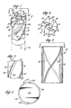
- the diamond end mill of Figure 1 generally designated as 10 comprises an end mill blank body 12 having, for example, four longitudinally extending flutes 14 equidistantly spaced circumferentially around the body 12.
- the body of the end mill may, for example, be fabricated from a hard and tough material such as cemented tungsten carbide.
- a groove 18 is formed in the leading edge 15 of each of the body between the flutes 14.
- Sintered polycrystalline diamond-like 30 material is formed in the helically formed groove 18.
- Cutting edges 32 are ground into the sintered diamond-like material 30 pressed in the grooves adjacent to the flutes of the drill blank 12.
- the tungsten carbide drill blank may then be metallurgically bonded to a steel or carbide drill shank 16 along juncture 17.
- the metallurgical bond may, for example, be a braze.
- the polycrystalline diamond-like material in the grooves may be either diamond or cubic boron nitride (CBN). To form polycrystalline diamond in the grooves, they are packed with diamond powder. To form polycrystalline cubic boron nitride, the grooves are packed with cubic boron nitride powder. PCD is used herein as a convenient abbreviation for polycrystalline diamond-like material, whether diamond or cubic boron nitride.
- FIG. 2 the end 13 of the mill further illustrates the grooves forming the leading edge 15 of the metal between the flutes, the polycrystalline diamond (PCD) being compacted and sintered within the grooves.
- a cutting edge or lip 32 is ground into the PCD material after the sintering process is complete (the schematically depicted process of Fig. 6).
- the cemented tungsten carbide cutter blank body is formed with, for example, four helically configured grooves 18 therein.
- the flutes 14 are formed in the body after the diamond-like material is sintered within the groove.
- the helically formed grooves are equidistantly spaced around the outer circumferential walls of the blank and provide a receptacle for the PCD powder compacted therein.
- the sides 20 of the helical groove preferably transition into a rounded bottom 22 of the groove. Identical sides 20 are formed in the other grooves. The reason for the rounded bottom of the groove is to assure that the diamond-like powder material is packed into the groove without any possibility of voids. If the sides of the groove were 90° to the bottom of the groove then the sharp 90° corners could cause stress risers and voids in the diamond-like material.
- an alternate rotary cutter blank 110 is illustrated with a pair of grooves 118 formed in the blank body 112.
- the grooves 18 and 118 are compacted with diamond-like powder 30 and 130 and sintered in a press.
- the polycrystalline diamond-like material is formed in the helical grooves of the tungsten carbide blank body.
- a solid mass of diamond-like material in grooves 18 and 118 is thus formed in the blank side walls of the end mill bodies 12 and 112.
- the end mill blank is then machined, usually by grinding or electrical discharge machining to form the flutes 14.
- a subsequent grinding or EDM process forms the cutting gage surface or cutting edges 32 on the sides of the blank bodies 12 and 112.
- a carbide blank having, for example, four flutes formed in the blank is formed slightly oversize (by up to 1 mm.) on the diameter of the end mill blank.
- the end mill is machined to the proper diameter after the diamond sintering process is completed.
- the end mill blank body is preferably formed from a cemented tungsten carbide material.
- the helically formed groove is formed in the body adjacent each of the flutes with a depth of about 1.2 mm and a width of the groove of about 1.5 mm, the sidewalls 20 transition into rounded bottom 22 of the helical groove to a wider opening at the surface of the flutes 14.
- the groove is so configured to assure that the diamond-like powder is packed in the groove without voids.
- the diamond-like material is preferably diamond powder having a size range from 3 to 60 microns.
- the preferred size range of the powder is from 4 to 30 microns.
- the binder for the diamond powder is cobalt which may be mixed with the diamond powder and packed into the grooves, or which may infiltrate into the diamond powder from adjacent cemented tungsten carbide.
- a suitable ratio of cobalt to diamond is 6 to 15 percent by weight cobalt. The percentage of cobalt is preferred to be 13 percent.
- a gap filling material of smaller sized diamond powder may be mixed with the larger particles of diamond.
- the gap filling diamond powder is preferred to be from 1 to 3 microns in size.
- the flutes in the tungsten carbide blank or body are preferably prepared by slightly rounding the corners of the leading edges adjacent to the flutes. The reason for “dulling" the corners at the flutes will become apparent with further discussion of the process.
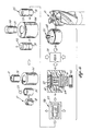
- the blank 12 is then placed in a "getter” can or receptacle 31.
- the mixed diamond powder and cobalt is then packed into the grooves 18.
- the "getter” is a reactive metal that reacts with contaminates and oxides to facilitate better diamond bonding.
- the getters combine with impurities in the mix to facilitate or achieve a better bond.
- a typical getter material is selected from the group consisting of zirconium, columbium, tantalum and hafnium.
- the receptacle 31 is formed of the columbium getter material and laid over the diamond powder pressed in the grooves formed at both of the flutes.
- the end mill body in the can is then run through a die 51 to make the blank more compact.
- the second can 53 of columbium then is run through a die 54 to completely seal the second can 53 over the first can 31.
- the sealed can containing the blank and now generally designated as 55 is then run through a pre-compact stage 56.
- the can 55 is first surrounded by salt 57 then is put in a pre-compact press 56 to further compact the can 55.
- the can is subjected to around 100 ksi (7000 kg/cm2) in the pre-compact press.
- the range of force on the can may be for example, 3500 to 7000 kg/cm2. This assures that the blank trapped within the columbium cans 50 and 53 is as dense as possible prior to the sintering process.
- the compressed can 55 is now ready for the sintering process. The reason the edge's are dulled is to prevent the columbium cans from being cut during the pre-compaction stage.
- the can 55 is loaded into a pyrophyllite cube.
- the cube generally designated as 60 is packed with salt rings 57 and lined with a graphite material 66.
- the cube 60 is then capped with a titanium disk 65 followed by a mica ring baffle 64 and another titanium disk 63.
- a relatively thick steel ring 62 surrounds a pyrophyllite cap material 61. Both ends of the pyrophyllite cube have the same assembly, thus closing the can 55 within the salt rings 57 in the center of the pyrophyllite cube 60.
- the assembled cube 60 then goes to the press 70.
- the cube 60 is pressed at a temperature of about 1,300 to 1,600°C at a sufficient pressure to form polycrystalline diamond in situ in the grooves, or about 1 million pounds per square inch (70,000 kg/cm2).
- the time in the press is approximately 10 minutes.
- the temperature is gradually increased to 1,400°C over a period of about 4 minutes, the cube 60 is held at temperature of 1,400 to 1,500°C for about 1 minute and then allowed to cool down for approximately 5 minutes.
- An important aspect of this process is that the heat up be relatively slow with a slow cool down period. This is done primarily to reduce residual stresses within the finished rotary cutter.
- the sintered can 55 is subsequently broken out of the pyrophyllite cube 60.
- the sintered end mill blank body is still housed within the cans 31 and 53 of columbium material.
- the enclosed end mill blank is then dropped into a bath of fused potassium hydroxide.
- the potassium hydroxide serves to remove the columbium can material from the blank.
- the blank body 12 after the sintering process, is then brazed to a mill shank 16.
- the blank with attached shank is then ground to the finished diameter prior to grinding the polycrystalline diamond and relief angles as required.
- the pre-sintered polycrystalline diamond may be fabricated using a patented process, U.S. Patent No. 4,797,241 assigned to Megadiamond and incorporated herein by reference.
- cubic boron nitride can be used in the fabrication of these mill cutters or the like in the place of PCD without departing from the scope of this invention.
Landscapes
- Engineering & Computer Science (AREA)
- Mechanical Engineering (AREA)
- Milling Processes (AREA)
- Drilling Tools (AREA)
- Cutting Tools, Boring Holders, And Turrets (AREA)
- Polishing Bodies And Polishing Tools (AREA)
Abstract
Description
- This invention relates to rotary cutting tools and more particularly to helically fluted end mills.
- Helically fluted end mills are the most commonly used milling tools and are generally required to perform severe machining operations under extremely adverse conditions. The cutting end of a helically fluted end mill includes at least a pair of cutting lips on opposite outside surfaces of the end mill blank.
- Oppositely directed cutting surfaces positioned at the cutting end of the mill blank are subjected to axial and torsional loads which create material demands on the fabrication of the milling tool. Obviously the material of the cutting lips should be as hard as possible to cut a work piece and it should be heat resistant as well to maintain the cutting edge of the mill at elevated temperatures. Moreover, the material of the body of the mill blank must be both rigid and tough to resist deflection and to maintain the integrity of the mill under loads while the milling cutter is being used. The foregoing requirements have resulted in compromises in material selection since hard materials tend to be brittle while tough materials tend to wear quite easily.
- This invention has application for other types of rotary cutting tools such as router bits, reamers and taps.
- The prior art teaches a combination of materials having the characteristics of hardness and wear-resistance at the cutting surfaces and toughness and rigidity of the body and shaft. It has been previously proposed to form the cutting surfaces of one material and the body and shaft of another. This has resulted in a variety of combinations such as cemented tungsten carbide or diamond inserts or tips on carbon steel or cemented tungsten carbide shafts. These combinations while individually useful have a common disadvantage, i.e. the braze connection between the insert or tip and a shaft. Tungsten carbide can be soldered or brazed directly to the steel or carbide shaft. However, a diamond tip or insert must first be adhered to a carbide substrate which is in turn soldered or brazed to the shaft. Diamond particles are typically formed into a compact or PCD (polycrystalline diamond) disc and bonded to a carbide substrate with a metallic catalyst in a high pressure-high temperature press. At atmospheric pressures, however, the metal which catalyzes the bonding of the diamond particles to each other and to the substrate in the press will also catalyze the conversion of diamond to graphite at temperatures above 700°C which will cause disintegration of the PCD compact. Accordingly a low temperature solder or braze connection is used to attach the substrate to the shaft. The aforementioned diamond discs as well as the diamond insert stud blanks, for example, are fabricated from a tungsten carbide substrate with a diamond layer sintered to a face of a substrate, the diamond layer being composed of polycrystalline material.
- The synthetic polycrystalline diamond insert is manufactured by Sii Megadiamond, Provo, Utah, a wholly owned subsidiary of Smith International, Inc.
- Two examples of patents assigned to Megadiamond describe cutting elements for drilling holes are U.S. Patents Nos. 4,527,643 and 4,627,503. Both of these patents utilize a braze type bonding element to secure the diamond cutters within a drill blank. Typically a low temperature solder or braze connection is used to attach the substrate to a shaft such as the shaft of a helical twist drill. This braze connection limits the effective life of such drilling tools since it is softer than either the substrate or the shaft. The braze thus becomes the weakest point of the tool construction and the limiting factor in the tool usage.
- U.S. Patent No. 4,762,445 teaches a helically fluted twist drill in which offset opposed veins of sintered abrasive particulate, such as diamond, are embedded within a drill blank made of a less abrasive material such as carbide. A disadvantage of the foregoing drill is that the veins of diamonds are merely brazed in place on the twist drill and tend to wear out rather quickly.
- The present invention overcomes the problems of the foregoing prior art by providing, for example, a concentration of polycrystalline diamond-like material formed in situ in each of a pair of flutes of a milling cutter blank.
- A rotary cutter has cutting edges along its length with at least a pair of grooves in its side walls and polycrystalline diamond-like material formed in situ within the grooves. The polycrystalline diamond-like material has a cutting edge formed along its leading edge. Preferably the body of the rotary cutter is formed of cemented tungsten carbide and has at least a pair of longitudinally extending flutes along its body, the polycrystalline diamond-like material in each of the grooves forming a leading edge adjacent a flute. The diamond-like material may be either diamond or cubic boron nitride.
- Preferably such a rotary cutter is formed by a process of forming at least a pair of longitudinally extending grooves in an outside surface of a rotary cutter blank of cemented tungsten carbide and filling the grooves with diamond-like material. The diamond-like material is bond in the grooves at a sufficient pressure to form polycrystalline diamond-like material. Preferably, longitudinally extending flutes are formed in the rotary cutter blank along a leading edge of the polycrystalline diamond-like material after forming the polycrystalline diamond-like material in situ.
- The above noted features and advantages of the present invention will be more fully understood upon a study of the following description in conjunction with the detailed drawings.
- FIG. 1 is a perspective view of a fluted end mill;
- FIG. 2 is an end view taken through 2-2 of FIG. 1;
- FIG. 3 is a perspective view of an end mill blank with four helical flutes machined therein;
- FIG. 4 is a side view of an end mill blank with a pair of helical flutes 180° one from the other;
- FIG. 5 is an end view taken through 5-5 of FIG. 4; and
- FIG. 6 is a semi-schematic diagram of the process steps involved to fabricate the end mill cutter.
- The diamond end mill of Figure 1 generally designated as 10 comprises an end mill
blank body 12 having, for example, four longitudinally extendingflutes 14 equidistantly spaced circumferentially around thebody 12. The body of the end mill may, for example, be fabricated from a hard and tough material such as cemented tungsten carbide. Agroove 18 is formed in the leadingedge 15 of each of the body between theflutes 14. Sintered polycrystalline diamond-like 30 material is formed in the helically formedgroove 18.Cutting edges 32 are ground into the sintered diamond-like material 30 pressed in the grooves adjacent to the flutes of the drill blank 12. The tungsten carbide drill blank may then be metallurgically bonded to a steel orcarbide drill shank 16 alongjuncture 17. The metallurgical bond may, for example, be a braze. - The polycrystalline diamond-like material in the grooves may be either diamond or cubic boron nitride (CBN). To form polycrystalline diamond in the grooves, they are packed with diamond powder. To form polycrystalline cubic boron nitride, the grooves are packed with cubic boron nitride powder. PCD is used herein as a convenient abbreviation for polycrystalline diamond-like material, whether diamond or cubic boron nitride.
- Turning now to Figure 2 the end 13 of the mill further illustrates the grooves forming the leading
edge 15 of the metal between the flutes, the polycrystalline diamond (PCD) being compacted and sintered within the grooves. A cutting edge orlip 32 is ground into the PCD material after the sintering process is complete (the schematically depicted process of Fig. 6). - Turning now to Figure 3 the cemented tungsten carbide cutter blank body is formed with, for example, four helically configured
grooves 18 therein. Preferably, theflutes 14 are formed in the body after the diamond-like material is sintered within the groove. The helically formed grooves are equidistantly spaced around the outer circumferential walls of the blank and provide a receptacle for the PCD powder compacted therein. Thesides 20 of the helical groove preferably transition into arounded bottom 22 of the groove.Identical sides 20 are formed in the other grooves. The reason for the rounded bottom of the groove is to assure that the diamond-like powder material is packed into the groove without any possibility of voids. If the sides of the groove were 90° to the bottom of the groove then the sharp 90° corners could cause stress risers and voids in the diamond-like material. - With reference now to Figure 4, an alternate rotary cutter blank 110 is illustrated with a pair of
grooves 118 formed in theblank body 112. - One could also provide diamond end mills with one or more grooves that are substantially parallel to an axis of the mill blank body (not shown).
- Further, one could provide cutters across the
ends 13 and 113 of theblank bodies - Referring now to FIGS. 1, 2 and 5, the
grooves like powder grooves end mill bodies flutes 14. A subsequent grinding or EDM process forms the cutting gage surface or cuttingedges 32 on the sides of theblank bodies - What follows is an example of a process of forming a 3/8 inch (9.5 mm) end mill cutter. Referring now to Fig. 6, a carbide blank having, for example, four flutes formed in the blank, is formed slightly oversize (by up to 1 mm.) on the diameter of the end mill blank. The end mill is machined to the proper diameter after the diamond sintering process is completed. As indicated before, the end mill blank body is preferably formed from a cemented tungsten carbide material. The helically formed groove is formed in the body adjacent each of the flutes with a depth of about 1.2 mm and a width of the groove of about 1.5 mm, the
sidewalls 20 transition into roundedbottom 22 of the helical groove to a wider opening at the surface of theflutes 14. As indicated before the groove is so configured to assure that the diamond-like powder is packed in the groove without voids. - The diamond-like material is preferably diamond powder having a size range from 3 to 60 microns. The preferred size range of the powder is from 4 to 30 microns. The binder for the diamond powder is cobalt which may be mixed with the diamond powder and packed into the grooves, or which may infiltrate into the diamond powder from adjacent cemented tungsten carbide. A suitable ratio of cobalt to diamond is 6 to 15 percent by weight cobalt. The percentage of cobalt is preferred to be 13 percent. A gap filling material of smaller sized diamond powder may be mixed with the larger particles of diamond. The gap filling diamond powder is preferred to be from 1 to 3 microns in size.
- The flutes in the tungsten carbide blank or body are preferably prepared by slightly rounding the corners of the leading edges adjacent to the flutes. The reason for "dulling" the corners at the flutes will become apparent with further discussion of the process. The blank 12 is then placed in a "getter" can or receptacle 31. The mixed diamond powder and cobalt is then packed into the
grooves 18. The "getter" is a reactive metal that reacts with contaminates and oxides to facilitate better diamond bonding. The getters combine with impurities in the mix to facilitate or achieve a better bond. A typical getter material is selected from the group consisting of zirconium, columbium, tantalum and hafnium. For example, thereceptacle 31 is formed of the columbium getter material and laid over the diamond powder pressed in the grooves formed at both of the flutes. The end mill body in the can is then run through a die 51 to make the blank more compact. Thesecond can 53 of columbium then is run through a die 54 to completely seal thesecond can 53 over thefirst can 31. The sealed can containing the blank and now generally designated as 55 is then run through apre-compact stage 56. Thecan 55 is first surrounded bysalt 57 then is put in apre-compact press 56 to further compact thecan 55. The can is subjected to around 100 ksi (7000 kg/cm₂) in the pre-compact press. The range of force on the can, may be for example, 3500 to 7000 kg/cm². This assures that the blank trapped within thecolumbium cans 50 and 53 is as dense as possible prior to the sintering process. Thecompressed can 55 is now ready for the sintering process. The reason the edge's are dulled is to prevent the columbium cans from being cut during the pre-compaction stage. - The
can 55 is loaded into a pyrophyllite cube. The cube generally designated as 60 is packed with salt rings 57 and lined with agraphite material 66. The cube 60 is then capped with a titanium disk 65 followed by amica ring baffle 64 and anothertitanium disk 63. A relativelythick steel ring 62 surrounds a pyrophyllite cap material 61. Both ends of the pyrophyllite cube have the same assembly, thus closing thecan 55 within the salt rings 57 in the center of the pyrophyllite cube 60. - The assembled cube 60 then goes to the
press 70. The cube 60 is pressed at a temperature of about 1,300 to 1,600°C at a sufficient pressure to form polycrystalline diamond in situ in the grooves, or about 1 million pounds per square inch (70,000 kg/cm²). The time in the press is approximately 10 minutes. In a specific example, the temperature is gradually increased to 1,400°C over a period of about 4 minutes, the cube 60 is held at temperature of 1,400 to 1,500°C for about 1 minute and then allowed to cool down for approximately 5 minutes. An important aspect of this process is that the heat up be relatively slow with a slow cool down period. This is done primarily to reduce residual stresses within the finished rotary cutter. - The sintered can 55 is subsequently broken out of the pyrophyllite cube 60. The sintered end mill blank body is still housed within the
cans - The
blank body 12, after the sintering process, is then brazed to amill shank 16. The blank with attached shank is then ground to the finished diameter prior to grinding the polycrystalline diamond and relief angles as required. - The pre-sintered polycrystalline diamond may be fabricated using a patented process, U.S. Patent No. 4,797,241 assigned to Megadiamond and incorporated herein by reference.
- As mentioned above, cubic boron nitride can be used in the fabrication of these mill cutters or the like in the place of PCD without departing from the scope of this invention.
- It will of course be realized that various modifications can be made in the design and operation of the present invention without departing from the spirit thereof. Thus, while the principal preferred construction and mode of operation of the invention have been explained in what is now considered to represent its best embodiments, which have been illustrated and described, it should be understood that within the scope of the appended claims, the invention may be practiced otherwise than as specifically illustrated and described.
Claims (8)
- A rotary cutter having cutting edges along its length and characterized by:
a rotary cutter blank having at least a pair of grooves in side walls of the blank; and
polycrystalline diamond-like material formed in situ within the grooves formed in the side walls, the polycrystalline diamond-like material having a cutting edge formed along its leading edge. - A rotary cutter as set forth in claim 1 comprising at least a pair of longitudinally extending flutes along the cutter blank, the polycrystalline diamond-like material in each of the grooves being formed in a leading edge of the cutter blank adjacent a flute.
- A rotary cutter as set forth in either of claims 1 or 2 wherein the cutter blank is cemented tungsten carbide.
- A rotary cutter as recited in any of the preceding claims further comprising a connecting shank made of steel or cemented tungsten carbide brazed to the cutter blank at one end.
- A rotary cutter as recited in any of the preceding claims wherein the grooves extend helically along the cutter.
- A process for forming a rotary cutter characterized by the steps of:
forming a rotary cutter blank of cemented tungsten carbide;
forming at least a pair of longitudinally extending grooves in an outside surface of the blank;
filling the grooves with diamond-like material;
bonding the diamond-like material in the grooves in the rotary cutter blank at a sufficient pressure to form polycrystalline diamond-like material; and
forming a cutting edge along a leading edge of the polycrystalline diamond-like material. - A process as set forth in claim 6 further comprising the step of forming longitudinally extending flutes in the rotary cutter blank along a leading edge of the polycrystalline diamond-like material after forming the polycrystalline diamond-like material in situ.
- The invention as set forth an any of the preceding claims wherein the diamond-like material comprises cubic boron nitride.
Applications Claiming Priority (2)
| Application Number | Priority Date | Filing Date | Title |
|---|---|---|---|
| US527967 | 1990-05-24 | ||
| US07/527,967 US5031484A (en) | 1990-05-24 | 1990-05-24 | Diamond fluted end mill |
Publications (3)
| Publication Number | Publication Date |
|---|---|
| EP0458434A2 true EP0458434A2 (en) | 1991-11-27 |
| EP0458434A3 EP0458434A3 (en) | 1992-03-11 |
| EP0458434B1 EP0458434B1 (en) | 1994-09-28 |
Family
ID=24103715
Family Applications (1)
| Application Number | Title | Priority Date | Filing Date |
|---|---|---|---|
| EP91301141A Expired - Lifetime EP0458434B1 (en) | 1990-05-24 | 1991-02-13 | Rotary cutter with Diamond-like cutting edges |
Country Status (6)
| Country | Link |
|---|---|
| US (1) | US5031484A (en) |
| EP (1) | EP0458434B1 (en) |
| JP (2) | JPH04217416A (en) |
| AT (1) | ATE112198T1 (en) |
| DE (1) | DE69104263T2 (en) |
| IE (1) | IE65906B1 (en) |
Cited By (6)
| Publication number | Priority date | Publication date | Assignee | Title |
|---|---|---|---|---|
| EP0582475A1 (en) * | 1992-08-06 | 1994-02-09 | British Aerospace Public Limited Company | Cutting tools of composite construction |
| WO1994020251A1 (en) * | 1993-03-09 | 1994-09-15 | Hydra Tools International Plc | Rotary cutter |
| WO1998056528A1 (en) * | 1997-06-13 | 1998-12-17 | Sandvik Ab | Method of making endmills |
| WO2003086689A1 (en) * | 2002-04-08 | 2003-10-23 | Third Wave Systems | High-frequency tooth pass cutting system |
| WO2005016583A1 (en) * | 2003-08-15 | 2005-02-24 | NUBIUS GROUP Präzisionswerkzeuge GmbH | Milling tool |
| US9194189B2 (en) | 2011-09-19 | 2015-11-24 | Baker Hughes Incorporated | Methods of forming a cutting element for an earth-boring tool, a related cutting element, and an earth-boring tool including such a cutting element |
Families Citing this family (43)
| Publication number | Priority date | Publication date | Assignee | Title |
|---|---|---|---|---|
| US5297456A (en) * | 1990-02-07 | 1994-03-29 | Gn Tool Co., Ltd. | Cutting tool with twisted edge and manufacturing method thereof |
| US5226760A (en) * | 1990-02-07 | 1993-07-13 | Gn Tool Co., Ltd. | Cutting tool with twisted edge and manufacturing method thereof |
| JP2556393B2 (en) * | 1990-02-07 | 1996-11-20 | ジーエヌツール株式会社 | Cutting tool having twisted blade and manufacturing method thereof |
| US5031484A (en) * | 1990-05-24 | 1991-07-16 | Smith International, Inc. | Diamond fluted end mill |
| GB2259263B (en) * | 1991-08-08 | 1995-11-22 | Habit Diamond Ltd | Wear resistant tools |
| US5115697A (en) * | 1991-08-16 | 1992-05-26 | Smith International, Inc. | Diamond rotary cutter flute geometry |
| US5273379A (en) * | 1992-01-23 | 1993-12-28 | Gn Tool Co., Ltd. | Blank material for drill and drill therefrom |
| US5443337A (en) * | 1993-07-02 | 1995-08-22 | Katayama; Ichiro | Sintered diamond drill bits and method of making |
| US5685671A (en) * | 1993-11-01 | 1997-11-11 | Smith International, Inc. | Diamond or CBN fluted center cutting end mill |
| AU2587095A (en) * | 1995-05-11 | 1996-11-29 | Smith International, Inc. | Diamond or cbn fluted center cutting end mill |
| US5667028A (en) * | 1995-08-22 | 1997-09-16 | Smith International, Inc. | Multiple diamond layer polycrystalline diamond composite cutters |
| US5766394A (en) * | 1995-09-08 | 1998-06-16 | Smith International, Inc. | Method for forming a polycrystalline layer of ultra hard material |
| US5979578A (en) | 1997-06-05 | 1999-11-09 | Smith International, Inc. | Multi-layer, multi-grade multiple cutting surface PDC cutter |
| DE19806864A1 (en) * | 1998-02-19 | 1999-08-26 | Beck August Gmbh Co | Reaming tool and method for its production |
| US6146476A (en) * | 1999-02-08 | 2000-11-14 | Alvord-Polk, Inc. | Laser-clad composite cutting tool and method |
| DE19912721C1 (en) * | 1999-03-20 | 2000-08-10 | Simon Karl Gmbh & Co Kg | Sintered metal milling disk production process comprises positioning of cutter inserts in metal powder filled in a pressing die cavity |
| GB0022448D0 (en) * | 2000-09-13 | 2000-11-01 | De Beers Ind Diamond | Method of making a tool insert |
| AU2002219416A1 (en) * | 2000-12-21 | 2002-07-01 | Element Six (Pty) Ltd. | Method of making a cutting tool |
| IL150014A (en) * | 2002-06-04 | 2005-09-25 | Iscar Ltd | Method for making a metal powdered compact |
| JP2008538536A (en) * | 2005-03-30 | 2008-10-30 | スミス インターナショナル,インコーポレイティド | End mill and manufacturing method thereof |
| JP2008087088A (en) * | 2006-09-29 | 2008-04-17 | Denso Corp | Cutting tool and method for manufacturing cutting tool |
| US9468980B2 (en) * | 2007-04-03 | 2016-10-18 | H. Sam Cho | Contoured PCD and PCBN segments for cutting tools containing such segments |
| US8052765B2 (en) * | 2007-04-03 | 2011-11-08 | Cho H Sam | Contoured PCD and PCBN for twist drill tips and end mills and methods of forming the same |
| US7431538B1 (en) * | 2007-04-12 | 2008-10-07 | Kennametal Inc. | End mill for orbital drilling of fiber reinforced plastic materials |
| IL200742A (en) * | 2009-09-03 | 2016-11-30 | Kennametal Inc | Rotary cutting tool having a cutting edge formed of veined pcd |
| PT2519378E (en) | 2009-12-31 | 2013-11-19 | Diamond Innovations Inc | Blank for the manufacture of a machining tool and method of use of a blank for the manufacture of a machining tool |
| US20110176879A1 (en) * | 2010-01-20 | 2011-07-21 | Cornelis Roelof Jonker | Superhard body, tool and method for making same |
| GB201002375D0 (en) | 2010-02-12 | 2010-03-31 | Element Six Production Pty Ltd | A superhard tip, method for making same and tool comprising same |
| CN101817102B (en) * | 2010-03-30 | 2012-07-04 | 浙江欣兴工具有限公司 | Annular drilling tool |
| GB201010061D0 (en) | 2010-06-16 | 2010-07-21 | Element Six Ltd | Rotary machine tools |
| GB201015541D0 (en) | 2010-09-17 | 2010-10-27 | Element Six Ltd | Twist drill assembly |
| USD649989S1 (en) * | 2011-06-29 | 2011-12-06 | Elmer's Products, Inc. | Dual helical cutter for pencil sharpener |
| GB201207447D0 (en) * | 2012-04-26 | 2012-06-13 | Exactaform Cutting Tools Ltd | Rotary cutting tool |
| DE102014207502B4 (en) * | 2014-04-17 | 2022-11-24 | Kennametal Inc. | rotary tool and tool head |
| US9533398B2 (en) | 2014-08-19 | 2017-01-03 | Us Synthetic Corporation | Positive relief forming of polycrystalline diamond structures and resulting cutting tools |
| WO2016065018A1 (en) * | 2014-10-22 | 2016-04-28 | Smith International, Inc. | Polycrystalline diamond-metal composite structures and method of manufacture |
| KR102188627B1 (en) * | 2016-11-15 | 2020-12-08 | 스미또모 덴꼬오 하드메탈 가부시끼가이샤 | Cutting tool |
| EP3569351B1 (en) * | 2018-05-14 | 2025-07-09 | AB Sandvik Coromant | Veined tool blank |
| DE102018113613B3 (en) * | 2018-06-07 | 2019-07-04 | SCHOTT Diamantwerkzeuge GmbH | Diamond tool and method of making a diamond tool |
| JP7512892B2 (en) | 2019-03-26 | 2024-07-09 | 三菱マテリアル株式会社 | Substrate for hard sintered body, hard sintered body and cutting tool |
| CN112706016B (en) * | 2020-12-24 | 2022-04-12 | 广东罗庚机器人有限公司 | Grinding treatment method and server suitable for engine crankshaft |
| USD1031801S1 (en) * | 2021-01-29 | 2024-06-18 | Sumitomo Electric Hardmetal Corp. | Cutting tool |
| WO2023146713A1 (en) * | 2022-01-28 | 2023-08-03 | Diamond Innovations, Inc. | Veined end mill tool blanks |
Family Cites Families (14)
| Publication number | Priority date | Publication date | Assignee | Title |
|---|---|---|---|---|
| US1977845A (en) * | 1928-12-22 | 1934-10-23 | Cleveland Twist Drill Co | Cutting and forming tool, implement, and the like and method of making same |
| US1887373A (en) * | 1929-03-14 | 1932-11-08 | Cleveland Twist Drill Co | Reamer and the like |
| US1887374A (en) * | 1929-04-10 | 1932-11-08 | Cleveland Twist Drill Co | Drill |
| JPS5766805A (en) * | 1980-10-06 | 1982-04-23 | Nippon Oil & Fats Co Ltd | Cutting tool of high hardness |
| DE8110928U1 (en) * | 1981-04-10 | 1981-12-03 | BIAX-Werkzeuge KG, Wezel & Co, Präzisionswerkzeugfabrik, 7133 Maulbronn | MILLING TOOL |
| DE3232686A1 (en) * | 1982-09-02 | 1984-03-08 | Hartmetallwerkzeugfabrik Andreas Maier GmbH + Co KG, 7959 Schwendi | ROTATIONAL CUTTING TOOL AND METHOD FOR THE PRODUCTION THEREOF |
| US4527643A (en) * | 1983-02-07 | 1985-07-09 | Megadiamond Industries Inc. | Rotary cutting member for drilling holes |
| US4627503A (en) * | 1983-08-12 | 1986-12-09 | Megadiamond Industries, Inc. | Multiple layer polycrystalline diamond compact |
| US4797241A (en) * | 1985-05-20 | 1989-01-10 | Sii Megadiamond | Method for producing multiple polycrystalline bodies |
| US4762445A (en) * | 1985-06-03 | 1988-08-09 | Precorp, Inc. | Composite sintered twist drill |
| JP2516362B2 (en) * | 1987-04-06 | 1996-07-24 | 東芝タンガロイ株式会社 | Carbide solid tool |
| JPS63251130A (en) * | 1987-04-06 | 1988-10-18 | Toshiba Tungaloy Co Ltd | Manufacture of small bore drill |
| JP2556393B2 (en) * | 1990-02-07 | 1996-11-20 | ジーエヌツール株式会社 | Cutting tool having twisted blade and manufacturing method thereof |
| US5031484A (en) * | 1990-05-24 | 1991-07-16 | Smith International, Inc. | Diamond fluted end mill |
-
1990
- 1990-05-24 US US07/527,967 patent/US5031484A/en not_active Expired - Lifetime
-
1991
- 1991-01-22 JP JP3005624A patent/JPH04217416A/en active Pending
- 1991-02-12 IE IE45991A patent/IE65906B1/en not_active IP Right Cessation
- 1991-02-13 EP EP91301141A patent/EP0458434B1/en not_active Expired - Lifetime
- 1991-02-13 AT AT91301141T patent/ATE112198T1/en not_active IP Right Cessation
- 1991-02-13 DE DE69104263T patent/DE69104263T2/en not_active Expired - Fee Related
-
1996
- 1996-11-27 JP JP31678096A patent/JP3372017B2/en not_active Expired - Fee Related
Cited By (7)
| Publication number | Priority date | Publication date | Assignee | Title |
|---|---|---|---|---|
| EP0582475A1 (en) * | 1992-08-06 | 1994-02-09 | British Aerospace Public Limited Company | Cutting tools of composite construction |
| WO1994020251A1 (en) * | 1993-03-09 | 1994-09-15 | Hydra Tools International Plc | Rotary cutter |
| WO1998056528A1 (en) * | 1997-06-13 | 1998-12-17 | Sandvik Ab | Method of making endmills |
| WO2003086689A1 (en) * | 2002-04-08 | 2003-10-23 | Third Wave Systems | High-frequency tooth pass cutting system |
| WO2005016583A1 (en) * | 2003-08-15 | 2005-02-24 | NUBIUS GROUP Präzisionswerkzeuge GmbH | Milling tool |
| US9194189B2 (en) | 2011-09-19 | 2015-11-24 | Baker Hughes Incorporated | Methods of forming a cutting element for an earth-boring tool, a related cutting element, and an earth-boring tool including such a cutting element |
| US9771497B2 (en) | 2011-09-19 | 2017-09-26 | Baker Hughes, A Ge Company, Llc | Methods of forming earth-boring tools |
Also Published As
| Publication number | Publication date |
|---|---|
| EP0458434B1 (en) | 1994-09-28 |
| IE910459A1 (en) | 1991-12-04 |
| JPH09207017A (en) | 1997-08-12 |
| US5031484A (en) | 1991-07-16 |
| EP0458434A3 (en) | 1992-03-11 |
| ATE112198T1 (en) | 1994-10-15 |
| JPH04217416A (en) | 1992-08-07 |
| DE69104263D1 (en) | 1994-11-03 |
| JP3372017B2 (en) | 2003-01-27 |
| IE65906B1 (en) | 1995-11-29 |
| DE69104263T2 (en) | 1995-05-04 |
Similar Documents
| Publication | Publication Date | Title |
|---|---|---|
| EP0458434B1 (en) | Rotary cutter with Diamond-like cutting edges | |
| US5070748A (en) | Diamond fluted end mill | |
| EP0528243B1 (en) | Diamond rotary cutter flute geometry | |
| US4991467A (en) | Diamond twist drill blank | |
| US6158304A (en) | Process for forming a center cutting end mill | |
| EP2533922B1 (en) | Superhard tool tip and use thereof | |
| US5645617A (en) | Composite polycrystalline diamond compact with improved impact and thermal stability | |
| US4604106A (en) | Composite polycrystalline diamond compact | |
| US7568534B2 (en) | Dual-edge working surfaces for polycrystalline diamond cutting elements | |
| GB2438073A (en) | Thermally stable ultra-hard material compact construction | |
| EP1351798B1 (en) | Method of making a cutting tool | |
| JP2594785B2 (en) | Diamond crystal-sintered carbide composite polycrystal | |
| US10583491B2 (en) | Tool | |
| CA2782802A1 (en) | Machining tool blank | |
| EP0833712A1 (en) | Diamond or cbn fluted center cutting end mill | |
| JPH09239613A (en) | Diamond rotary cutter | |
| US6994615B2 (en) | Cutting tools with two-slope profile | |
| JP3567381B2 (en) | Cutting tool and method of manufacturing cutting tool | |
| WO2024223247A1 (en) | A cutting element and methods of making same |
Legal Events
| Date | Code | Title | Description |
|---|---|---|---|
| PUAI | Public reference made under article 153(3) epc to a published international application that has entered the european phase |
Free format text: ORIGINAL CODE: 0009012 |
|
| AK | Designated contracting states |
Kind code of ref document: A2 Designated state(s): AT DE FR GB IT SE |
|
| PUAL | Search report despatched |
Free format text: ORIGINAL CODE: 0009013 |
|
| AK | Designated contracting states |
Kind code of ref document: A3 Designated state(s): AT DE FR GB IT SE |
|
| 17P | Request for examination filed |
Effective date: 19920814 |
|
| 17Q | First examination report despatched |
Effective date: 19930609 |
|
| GRAA | (expected) grant |
Free format text: ORIGINAL CODE: 0009210 |
|
| AK | Designated contracting states |
Kind code of ref document: B1 Designated state(s): AT DE FR GB IT SE |
|
| REF | Corresponds to: |
Ref document number: 112198 Country of ref document: AT Date of ref document: 19941015 Kind code of ref document: T |
|
| REF | Corresponds to: |
Ref document number: 69104263 Country of ref document: DE Date of ref document: 19941103 |
|
| ITF | It: translation for a ep patent filed | ||
| EAL | Se: european patent in force in sweden |
Ref document number: 91301141.7 |
|
| ET | Fr: translation filed | ||
| PLBE | No opposition filed within time limit |
Free format text: ORIGINAL CODE: 0009261 |
|
| STAA | Information on the status of an ep patent application or granted ep patent |
Free format text: STATUS: NO OPPOSITION FILED WITHIN TIME LIMIT |
|
| 26N | No opposition filed | ||
| REG | Reference to a national code |
Ref country code: GB Ref legal event code: IF02 |
|
| PGFP | Annual fee paid to national office [announced via postgrant information from national office to epo] |
Ref country code: FR Payment date: 20020117 Year of fee payment: 12 |
|
| PGFP | Annual fee paid to national office [announced via postgrant information from national office to epo] |
Ref country code: AT Payment date: 20020118 Year of fee payment: 12 Ref country code: DE Payment date: 20020118 Year of fee payment: 12 Ref country code: SE Payment date: 20020118 Year of fee payment: 12 |
|
| PG25 | Lapsed in a contracting state [announced via postgrant information from national office to epo] |
Ref country code: AT Free format text: LAPSE BECAUSE OF NON-PAYMENT OF DUE FEES Effective date: 20030213 |
|
| PG25 | Lapsed in a contracting state [announced via postgrant information from national office to epo] |
Ref country code: SE Free format text: LAPSE BECAUSE OF NON-PAYMENT OF DUE FEES Effective date: 20030214 |
|
| REG | Reference to a national code |
Ref country code: GB Ref legal event code: 732E |
|
| PG25 | Lapsed in a contracting state [announced via postgrant information from national office to epo] |
Ref country code: DE Free format text: LAPSE BECAUSE OF NON-PAYMENT OF DUE FEES Effective date: 20030902 |
|
| EUG | Se: european patent has lapsed | ||
| PG25 | Lapsed in a contracting state [announced via postgrant information from national office to epo] |
Ref country code: FR Free format text: LAPSE BECAUSE OF NON-PAYMENT OF DUE FEES Effective date: 20031031 |
|
| REG | Reference to a national code |
Ref country code: FR Ref legal event code: ST |
|
| PG25 | Lapsed in a contracting state [announced via postgrant information from national office to epo] |
Ref country code: IT Free format text: LAPSE BECAUSE OF NON-PAYMENT OF DUE FEES Effective date: 20050213 |
|
| PGFP | Annual fee paid to national office [announced via postgrant information from national office to epo] |
Ref country code: GB Payment date: 20100224 Year of fee payment: 20 |
|
| REG | Reference to a national code |
Ref country code: GB Ref legal event code: PE20 Expiry date: 20110212 |
|
| PG25 | Lapsed in a contracting state [announced via postgrant information from national office to epo] |
Ref country code: GB Free format text: LAPSE BECAUSE OF EXPIRATION OF PROTECTION Effective date: 20110212 |