EP0458432B1 - Retainer for a combined surgical suture-needle device - Google Patents
Retainer for a combined surgical suture-needle device Download PDFInfo
- Publication number
- EP0458432B1 EP0458432B1 EP91301067A EP91301067A EP0458432B1 EP 0458432 B1 EP0458432 B1 EP 0458432B1 EP 91301067 A EP91301067 A EP 91301067A EP 91301067 A EP91301067 A EP 91301067A EP 0458432 B1 EP0458432 B1 EP 0458432B1
- Authority
- EP
- European Patent Office
- Prior art keywords
- panel
- retainer
- suture
- needle
- possesses
- Prior art date
- Legal status (The legal status is an assumption and is not a legal conclusion. Google has not performed a legal analysis and makes no representation as to the accuracy of the status listed.)
- Expired - Lifetime
Links
Images


Classifications
-
- A—HUMAN NECESSITIES
- A61—MEDICAL OR VETERINARY SCIENCE; HYGIENE
- A61B—DIAGNOSIS; SURGERY; IDENTIFICATION
- A61B17/00—Surgical instruments, devices or methods, e.g. tourniquets
- A61B17/04—Surgical instruments, devices or methods, e.g. tourniquets for suturing wounds; Holders or packages for needles or suture materials
- A61B17/06—Needles ; Sutures; Needle-suture combinations; Holders or packages for needles or suture materials
- A61B17/06114—Packages or dispensers for needles or sutures
- A61B17/06133—Packages or dispensers for needles or sutures of parallelepipedal shape, e.g. made of rectangular or slightly oval panels
- A61B17/06138—Packages or dispensers for needles or sutures of parallelepipedal shape, e.g. made of rectangular or slightly oval panels including a retainer comprising three or more foldable panels
-
- A—HUMAN NECESSITIES
- A61—MEDICAL OR VETERINARY SCIENCE; HYGIENE
- A61B—DIAGNOSIS; SURGERY; IDENTIFICATION
- A61B17/00—Surgical instruments, devices or methods, e.g. tourniquets
- A61B17/04—Surgical instruments, devices or methods, e.g. tourniquets for suturing wounds; Holders or packages for needles or suture materials
- A61B17/06—Needles ; Sutures; Needle-suture combinations; Holders or packages for needles or suture materials
- A61B17/06114—Packages or dispensers for needles or sutures
- A61B2017/06142—Packages or dispensers for needles or sutures having needle- or suture- retaining members, e.g. holding tabs or needle parks
- A61B2017/06147—Foam blocks, e.g. slitted
-
- A—HUMAN NECESSITIES
- A61—MEDICAL OR VETERINARY SCIENCE; HYGIENE
- A61B—DIAGNOSIS; SURGERY; IDENTIFICATION
- A61B17/00—Surgical instruments, devices or methods, e.g. tourniquets
- A61B17/04—Surgical instruments, devices or methods, e.g. tourniquets for suturing wounds; Holders or packages for needles or suture materials
- A61B17/06—Needles ; Sutures; Needle-suture combinations; Holders or packages for needles or suture materials
- A61B17/06114—Packages or dispensers for needles or sutures
- A61B2017/06152—Packages or dispensers for needles or sutures containing a suture wound in a figure-8 configuration
Definitions
- This invention relates to a retainer for a combined surgical needle-suture device, also commonly referred to as an "armed suture” or merely a “suture”, as part of a suture package.
- Retainers for sutures are known, inter alia , from U.S. Patent Nos.
- the suture retainer should possess good storing qualities, provide safety in handling and permit ready access to, and removal of, the stored sutures.
- an armed suture retainer comprising four interconnected panels, namely, a needle retaining panel, a front cover panel connected to the needle retaining panel, a suture winding panel connected to the front cover panel and a fold-over panel connected to the suture winding panel.
- suture retainer possesses several advantages over known types of retainers, e.g., as described in U.S. Patent No. 4,249,656 referred to supra .
- a particularly important advantage of the suture retainer herein lies in the relative ease with which operating room personnel are able to view the needles and grasp them with forceps to effect their removal. These capabilities are made possible by the configurations of the first and second panels which, in the fully folded retainer, permit a highly visible needle display section from which each needle in the retainer can be easily removed.
- Fig. 1 illustrates a fully unfolded armed suture retainer 10 in accordance with this invention
- Fig. 2 illustrates retainer 10 in the fully folded condition which it assumes when received within the pocket of an outer suture package, e.g., as described in EP-A-0498093.
- Retainer 10 is provided as a series of four interconnected panels, namely, needle retainer panel 11 possessing an upper sloping edge 27, front cover panel 12 which also possesses an upper sloping edge 28, suture winding panel 13 (which also functions as the rear panel of the fully folded retainer) and fold-over panel 14.
- Retainer 10 is preferably formed from a single sheet of suitable material, e.g., stiff paper or paperboard such as 5 point to 12 point solid, TYVEK (Registered Trade Mark), bleached sulfate board, plastics, foils, laminates, and the like, which is die cut to provide the desired configuration.
- the panels are joined to each other along perforate, or score, lines 15, 32 (and its associated gusset sections 19a and 19b) and 17.
- Central gusset sections 19a and 19b accommodate a limited degree of expansion of the retainer in its loaded, fully folded condition.
- Other gusset configurations can also be employed for this purpose, e.g., a continuous pair of parallel fold lines or perforations which provide a narrow expansion section (line 49a and 49b defining gusset 62 in the retainer of Fig. 3).
- the retainer To load needle component 30 with its attached suture component 31 into retainer 10, the retainer is first mounted on a winding fixture by means of loading pins (not shown) which project through openings 18 in panel 13. The point of needle 30 is then inserted in die cut 23 which is shaped somewhat like a reversed "S" by threading the point under the upper and the lower half of the reversed "S” cut. Slight tension is maintained on suture 31 from this stage of the loading procedure to its conclusion to ensure that needle 30 will maintain its placement in die cut 23 as previously described. The shank of needle 30 is then threaded through one of teardrop-shaped cutouts 24 or 24', cutout 24 being used for smaller needles (as shown in Fig. 2) and cutout 24' being used for larger needles.
- Retainer 40 is provided as a series of four interconnected panels, namely, needle retainer panel 41 possessing an elliptical flap 53 defined by an arcuately shaped perforated fold line 53', front cover panel 42 possessing upper sloping edge 58, suture winding panel 43 which also functions as the rear panel of the fully folded retainer, and fold over panel 44.
- Needle retainer panel 41 possesses an arcuately serrated edge 57 of sinusoidal pattern configured to retain surgical needles thereon. The serrated edge 57 replaces cut-outs 24 and 24' and die cut 23 of the embodiment of Fig. 1 and provides an alternative means for needle retention.
- a pair of inverted "J-cuts" 54 are located in spaced relation along arcuate score line 53'.
- the "J-cuts" 54 provide two parabolic openings in the elliptical panel. These openings permit sterilizing gas to readily enter the retainer in its fully folded condition.
- "J-cuts" 54 provide two parabolic fingers extending upwardly and coplanar with needle retainer panel 41. These fingers provide “saddles” against or around which the needle shank and attached suture may be positioned.
- Panels 42 and 43 are joined together by parallel score lines 49a and 49b, to provide central gusset section 62.
- needle retaining panel 81 is connected to needle protecting panel 82 through single perforate score 90, panel 82 being connected to suture winding panel 83 (which is also the rear panel of the fully folded retainer) through double perforate score 91, panel 83 being connected to fold-over panel 84 through double perforate score 92.
- Diamond-shaped cutouts 89 and 89' are provided along upper sloping edge 88 of panel 81 in the region receiving needle components 100 and 100' (Fig. 4) of two surgical suture-needle devices.
- needle retaining panel 81 is folded over at perforate score 90 upon needle protecting panel 82 and the surgical suture components of the combined suture-needle devices (not shown) are wound in a figure "8" pattern upon suture winding panel 83 with the aid of loading pins projecting through openings 96 in much the same manner as previously described in connection with the suture retainer embodiment of Figs. 1 and 2.
- Combined overlying panels 81 and 82 are thereafter folded over at double perforate score 91 upon suture winding panel 83 to slightly compress the wound sutures and retain them in place on panel 83.
- Panel 84 is then folded over at double perforate score 92 upon the reverse side of panel 82, die-cut locking tabs 97 and 98 on panel 84 cooperating with die-cut locking slots 97' and 98' on panel 82 to provide the nearly fully folded retainer shown in Fig. 5.
- outer extension panel 85 is folded over at double perforate score 93 upon both inner extension panel 86 and exposed needles 100 and 100' with die-cut tab locking 99 on panel 85 engaging the upper edge of fold-over panel 84 to provide the fully folded suture retainer shown in Fig. 6.
- inner extension panel 86 is advantageously provided with a die-cut separation line 95 and perforate score 95' which allows the entire combined extension panel 85, 86 to be conveniently separated from panel 83 or folded back upon itself thus permitting access to needles 100 and 100' from the reverse side of retainer 80 as well as from its front side. Even when combined extension 85, 86 is not-separated from panel 83, the combined extension may be folded back along separation line 94 and perforate score 95' to provide needle visibility and accessibility from the rear of retainer 80.
- Outer extension panel 85 possesses a knurled section 102 which facilitates the opening of fully closed retainer 80 by providing a surface for easy engagement of the lower section of extension panel 85.
- retainer 110 features four panels, namely, needle retaining panel 111, needle protecting panel 112, suture winding panel 113 and fold-over panel 114.
- Double perforated scores 120 and 121 define gussets which allow for expansion of the loaded retainer in its closed condition.
- Raised ribs 138a and 138b project outwards from the reverse sides of fold over panel 114 and extension panel 105, respectively.
- raised ribs 138a provide a slight concave bend to fold-over panel 114, which enables 114 to resist any tendency to thrust away from needle retainer panel 111.
- Needle protection panel 112 possesses a trapezoidal shaped locking slit 135.
- locking tab 130 folds back at a 180° angle upon its score line 132 and cooperates with closing slit 135 of panel 112 to provide a completely secured retainer.
- Triangular panel 136 folds over upon perforate score line 137 and secures a suture thread to retainer panel 113.
- Extension panel 105 possesses convex sides 127a and 127b which facilitate the opening of retainer 110 by operating room personnel. When retainer member 110 is in a fully closed position, convex sides 127a and 127b extend outwards from the sides of retainer 80 and provide two areas for easy engagement of extension panel 105.
- Needle retaining panel 111 possesses a sinusoidal serration configuration 117 and a pair of "J" cuts 119 similar in design and function to the corresponding configurations of retainer 40 of Fig. 3.
- Retainer 140 features four panels, namely, needle retaining panel 141, front cover panel 142, suture winding panel 143, and foldover panel 144.
- Double perforated scores 151 define a gusset which allows for expansion of the loaded retainer in its closed condition.
- Front cover panel 142 possesses an upper sloping edge 154 which slopes upward to form a rounded projection 155.
- Suture winding panel 143 is significantly narrower than the suture winding panels of other embodiments described herein. The narrower panel facilitates winding of the suture and minimizes the possibility that suture loops may become entangled.
- Suture winding panel 143 possesses triangular shaped extension panel 145 which folds over along perforated score line 146 to provide a needle protection flap in the loaded and closed condition of the retainer card. When panel 143 is folded over onto panel 142, slit 153 can be made to engage rounded projection 155 thus locking the two panels together.
- Bell-shaped fold-over panel 144 possesses a tab 156 which cooperates with slit 157 to secure a wound suture upon suture winding panel 143. Die cut 159 cooperates with die cut 160 to provide a snap-lock feature which maintains the retainer in the fully closed condition.
- retainer 170 possesses four panels, namely, needle-retainer panel 171, front cover panel 172, suture-winding panel 173 and fold-over panel 174.
- the openings 188 of suture winding panel 173 which receive the loaded pins are positioned further apart than in previous embodiments. This positioning reduces the likelihood of suture entanglement since the freedom of movement of the wound suture is limited to one direction (i.e., inwardly). In addition, loop positioning will be better achieved and secured by compression of adjoining panels more closely adjacent the fold-lines.
- Triangular fold-over panel 174 possesses outer edge 192 which, in the folded condition of the retainer, interlocks with slit 187 to secure the wound suture to suture winding panel 173.
- retainer 200 possesses four panels, namely, needle retainer panel 201, front cover panel 202, suture winding panel 203, and fold over panel 204.
- Double perforated score lines 210, 211 and 212 constitute gussets which permit expansion of the retainer in its loaded, closed condition.
- Needle retainer panel 201 possesses foam block 208 which provides an alternate means of needle retention.
- Suture winding panel 203 possesses triangular extension panel 205 foldable along perforated line 206. Fold over panel 204 and extension panel 217 possess slightly raised ribs 207 and 222, respectively.
- Raised rib 207 imparts a slight concave bend to fold-over panel 204 which enables 204 to resist a tendency to thrust away from needle retainer panel 201.
- Raised rib 222 functions in a similar manner where extension panel 217 is concerned.
- Locking tab 213 is defined along double score line 214. When retainer 200 is in the fully closed condition, locking tab 213 folds back along double score line 214 to cooperate with closing slit 215 of panel 202 and provide a completely secured retainer. In the closed position, outer extension panel 217 folds over at double perforated line 218. Tab 221 folds along arcuate perforated line 223 to fit under front cover panel 202 thus providing protection for the secured needle.
- the retainers of the invention can be packaged within, for example, a foil package or a so-called "breather pouch" (not shown).
Abstract
Description
- This invention relates to a retainer for a combined surgical needle-suture device, also commonly referred to as an "armed suture" or merely a "suture", as part of a suture package. Retainers for sutures are known, inter alia, from U.S. Patent Nos. 3,857,484; 3,939,969; 3,951,261; 3,985,227; 4,063,638; 4,089,409; 4,120,395; 4,192,420; 4,249,656; 4,427,109; 4,253,563; 4,406,363; 4,412,614; 4,483,437; 4,491,218; 4,555,016; 4,572,363; 4,574,948; 4,574,957; 4,615,435; 4,708,241 and 4,813,537.
- As an essential component of a suture package, the suture retainer should possess good storing qualities, provide safety in handling and permit ready access to, and removal of, the stored sutures.
- The characterising features of the present invention are set out in claim 1 below, which has a prior art preamble based on the disclosure of US-A-4249656.
- By way of meeting the foregoing criteria, there is provided in accordance with this invention, an armed suture retainer comprising four interconnected panels, namely, a needle retaining panel, a front cover panel connected to the needle retaining panel, a suture winding panel connected to the front cover panel and a fold-over panel connected to the suture winding panel.
- The foregoing suture retainer possesses several advantages over known types of retainers, e.g., as described in U.S. Patent No. 4,249,656 referred to supra. A particularly important advantage of the suture retainer herein lies in the relative ease with which operating room personnel are able to view the needles and grasp them with forceps to effect their removal. These capabilities are made possible by the configurations of the first and second panels which, in the fully folded retainer, permit a highly visible needle display section from which each needle in the retainer can be easily removed.
In the accompanying drawings: - Fig. 1 is a plan view of one embodiment of an armed suture retainer in accordance with this invention loaded with a combined surgical needle-suture device and shown in the open condition;
- Fig. 2 is a plan view of the armed suture retainer of Fig. 1 shown in the fully folded condition;
- Fig. 3 is a plan view of another embodiment of an armed suture retainer in accordance with this invention shown in the fully unfolded condition;
- Figs. 4, 5 and 6 are plan views of another embodiment of the armed suture retainer herein also shown in the fully unfolded, partially folded and fully folded conditions, respectively; and,
- Figs. 7-10 are plan views of still other embodiments of an armed suture retainer in accordance with this invention shown in the fully unfolded condition.
- Fig. 1 illustrates a fully unfolded
armed suture retainer 10 in accordance with this invention and Fig. 2 illustratesretainer 10 in the fully folded condition which it assumes when received within the pocket of an outer suture package, e.g., as described in EP-A-0498093. -
Retainer 10 is provided as a series of four interconnected panels, namely,needle retainer panel 11 possessing an upper slopingedge 27,front cover panel 12 which also possesses an upper slopingedge 28, suture winding panel 13 (which also functions as the rear panel of the fully folded retainer) and fold-overpanel 14.Retainer 10 is preferably formed from a single sheet of suitable material, e.g., stiff paper or paperboard such as 5 point to 12 point solid, TYVEK (Registered Trade Mark), bleached sulfate board, plastics, foils, laminates, and the like, which is die cut to provide the desired configuration. The panels are joined to each other along perforate, or score,lines 15, 32 (and its associatedgusset sections 19a and 19b) and 17.Central gusset sections 19a and 19b accommodate a limited degree of expansion of the retainer in its loaded, fully folded condition. Other gusset configurations can also be employed for this purpose, e.g., a continuous pair of parallel fold lines or perforations which provide a narrow expansion section (line 49a and49b defining gusset 62 in the retainer of Fig. 3). - In the fully folded condition of the retainer and as shown in Fig. 2, a portion of
needle 30 is readily visible in the upper section of the retainer and is easily gripped by forceps for removal. Die cut 25 cooperates with diecut 26 to provide a snap-lock feature which maintains the retainer in the fully folded condition. Roundedindentations - To load
needle component 30 with its attachedsuture component 31 intoretainer 10, the retainer is first mounted on a winding fixture by means of loading pins (not shown) which project throughopenings 18 inpanel 13. The point ofneedle 30 is then inserted in diecut 23 which is shaped somewhat like a reversed "S" by threading the point under the upper and the lower half of the reversed "S" cut. Slight tension is maintained onsuture 31 from this stage of the loading procedure to its conclusion to ensure thatneedle 30 will maintain its placement in diecut 23 as previously described. The shank ofneedle 30 is then threaded through one of teardrop-shaped cutouts 24 or 24',cutout 24 being used for smaller needles (as shown in Fig. 2) and cutout 24' being used for larger needles. Afterpanel 11 has been folded over ontopanel 12,suture 31 is wound in a figure "8" pattern around the loading pins projecting throughopenings 18 inpanel 13.Retainer 10, now loaded withneedle 30 and attachedsuture 31, is released from the loading pins,panel 14 is folded over onpanel 13 and the partly folded-over structure is given a final folding alongperforate line 32 andgussets 19a and 19b. Finally, a slight counter-directional movement of the upper section of the retainer against its lower section sets the aforementioned snap-lock in place providing the fully assembled, loaded retainer of Fig. 2. - Referring to Fig. 3, there is illustrated another embodiment of the armed suture retainer of the present invention.
Retainer 40 is provided as a series of four interconnected panels, namely,needle retainer panel 41 possessing anelliptical flap 53 defined by an arcuately shaped perforated fold line 53',front cover panel 42 possessing upper sloping edge 58,suture winding panel 43 which also functions as the rear panel of the fully folded retainer, and fold overpanel 44.Needle retainer panel 41 possesses an arcuatelyserrated edge 57 of sinusoidal pattern configured to retain surgical needles thereon. Theserrated edge 57 replaces cut-outs 24 and 24' and diecut 23 of the embodiment of Fig. 1 and provides an alternative means for needle retention. - Again, referring to Fig.3, a pair of inverted "J-cuts" 54 are located in spaced relation along arcuate score line 53'. When
elliptical panel 53 is folded downward along the arcuate score line 53', the "J-cuts" 54 provide two parabolic openings in the elliptical panel. These openings permit sterilizing gas to readily enter the retainer in its fully folded condition. Additionally, whenelliptical panel 53 is folded downward, "J-cuts" 54 provide two parabolic fingers extending upwardly and coplanar withneedle retainer panel 41. These fingers provide "saddles" against or around which the needle shank and attached suture may be positioned.Panels parallel score lines 49a and 49b, to providecentral gusset section 62. - Once the needles are secured within or against a sinusoidal curve of arcuately
serrated edge 57 ofelliptical panel 53, the latter is folded over at arcuate edge 53'. The arcuate shape of 53' preventsextension panel 53 from folding flat against retainingpanel 41. Whenneedle retaining panel 41 is folded over atperforate score 45 uponfront cover panel 42,elliptical panel 53 serves to spaceneedle retaining panel 41 fromfront cover panel 42, thereby greatly improving the visibility and accessibility of needle components. In this position, the needles are securely retained by engagement withserrations 54 ofelliptical panel 53 andfront cover panel 42. - Referring to the embodiment of
armed suture retainer 80 of Figs. 4-6,needle retaining panel 81 is connected toneedle protecting panel 82 through singleperforate score 90,panel 82 being connected to suture winding panel 83 (which is also the rear panel of the fully folded retainer) through doubleperforate score 91,panel 83 being connected to fold-overpanel 84 through doubleperforate score 92. Diamond-shaped cutouts 89 and 89' are provided along upper slopingedge 88 ofpanel 81 in the region receivingneedle components 100 and 100' (Fig. 4) of two surgical suture-needle devices. Once the needles are secured withinserrations 101 ofextension panel 87, the latter folds over slopingedge 88 to provide additional protection for the needles. With the needles in place andextension panel 87 folded over,needle retaining panel 81 is folded over atperforate score 90 uponneedle protecting panel 82 and the surgical suture components of the combined suture-needle devices (not shown) are wound in a figure "8" pattern uponsuture winding panel 83 with the aid of loading pins projecting throughopenings 96 in much the same manner as previously described in connection with the suture retainer embodiment of Figs. 1 and 2. Combinedoverlying panels perforate score 91 uponsuture winding panel 83 to slightly compress the wound sutures and retain them in place onpanel 83.Panel 84 is then folded over at doubleperforate score 92 upon the reverse side ofpanel 82, die-cut locking tabs panel 84 cooperating with die-cut locking slots 97' and 98' onpanel 82 to provide the nearly fully folded retainer shown in Fig. 5. Finally,outer extension panel 85 is folded over at doubleperforate score 93 upon bothinner extension panel 86 and exposedneedles 100 and 100' with die-cut tab locking 99 onpanel 85 engaging the upper edge of fold-overpanel 84 to provide the fully folded suture retainer shown in Fig. 6. The lower edge ofinner extension panel 86 is advantageously provided with a die-cut separation line 95 and perforate score 95' which allows the entire combinedextension panel panel 83 or folded back upon itself thus permitting access toneedles 100 and 100' from the reverse side ofretainer 80 as well as from its front side. Even when combinedextension panel 83, the combined extension may be folded back alongseparation line 94 and perforate score 95' to provide needle visibility and accessibility from the rear ofretainer 80.Outer extension panel 85 possesses aknurled section 102 which facilitates the opening of fully closedretainer 80 by providing a surface for easy engagement of the lower section ofextension panel 85. - Referring to Fig. 7, illustrating still another embodiment of the suture retainer of the present invention,
retainer 110 features four panels, namely,needle retaining panel 111,needle protecting panel 112,suture winding panel 113 and fold-overpanel 114. Double perforatedscores - Raised
ribs 138a and 138b project outwards from the reverse sides of fold overpanel 114 andextension panel 105, respectively. Whenretainer 110 is in the closed position, raisedribs 138a provide a slight concave bend to fold-overpanel 114, which enables 114 to resist any tendency to thrust away fromneedle retainer panel 111. -
Needle protection panel 112 possesses a trapezoidal shapedlocking slit 135. Whenretainer 110 is in the fully closed position, lockingtab 130 folds back at a 180° angle upon itsscore line 132 and cooperates withclosing slit 135 ofpanel 112 to provide a completely secured retainer. - Along the lower edge of the
suture winding panel 113 is atriangular extension panel 136 connected towinding panel 113 by singleperforate score line 137.Triangular panel 136 folds over uponperforate score line 137 and secures a suture thread toretainer panel 113. -
Extension panel 105 possesses convexsides 127a and 127b which facilitate the opening ofretainer 110 by operating room personnel. Whenretainer member 110 is in a fully closed position, convexsides 127a and 127b extend outwards from the sides ofretainer 80 and provide two areas for easy engagement ofextension panel 105. -
Needle retaining panel 111 possesses asinusoidal serration configuration 117 and a pair of "J" cuts 119 similar in design and function to the corresponding configurations ofretainer 40 of Fig. 3. - Referring to Fig. 8, there is illustrated yet another embodiment of the present invention.
Retainer 140 features four panels, namely,needle retaining panel 141,front cover panel 142,suture winding panel 143, andfoldover panel 144. Doubleperforated scores 151 define a gusset which allows for expansion of the loaded retainer in its closed condition.Front cover panel 142 possesses an uppersloping edge 154 which slopes upward to form arounded projection 155. - Suture winding
panel 143 is significantly narrower than the suture winding panels of other embodiments described herein. The narrower panel facilitates winding of the suture and minimizes the possibility that suture loops may become entangled. Suture windingpanel 143 possesses triangular shapedextension panel 145 which folds over alongperforated score line 146 to provide a needle protection flap in the loaded and closed condition of the retainer card. Whenpanel 143 is folded over ontopanel 142, slit 153 can be made to engagerounded projection 155 thus locking the two panels together. Bell-shaped fold-overpanel 144 possesses atab 156 which cooperates withslit 157 to secure a wound suture uponsuture winding panel 143. Die cut 159 cooperates with die cut 160 to provide a snap-lock feature which maintains the retainer in the fully closed condition. - Referring to Figure 9, illustrating still another embodiment of the suture retainer of the present invention,
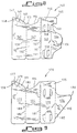
retainer 170 possesses four panels, namely, needle-retainer panel 171,front cover panel 172, suture-windingpanel 173 and fold-overpanel 174. Theopenings 188 ofsuture winding panel 173 which receive the loaded pins are positioned further apart than in previous embodiments. This positioning reduces the likelihood of suture entanglement since the freedom of movement of the wound suture is limited to one direction (i.e., inwardly). In addition, loop positioning will be better achieved and secured by compression of adjoining panels more closely adjacent the fold-lines. Triangular fold-overpanel 174 possessesouter edge 192 which, in the folded condition of the retainer, interlocks withslit 187 to secure the wound suture to suture windingpanel 173. - Referring to Figure 10 illustrating still another embodiment of the present invention,
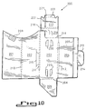
retainer 200 possesses four panels, namely,needle retainer panel 201,front cover panel 202,suture winding panel 203, and fold overpanel 204. Doubleperforated score lines Needle retainer panel 201 possessesfoam block 208 which provides an alternate means of needle retention. Suture windingpanel 203 possessestriangular extension panel 205 foldable alongperforated line 206. Fold overpanel 204 andextension panel 217 possess slightly raisedribs rib 207 imparts a slight concave bend to fold-overpanel 204 which enables 204 to resist a tendency to thrust away fromneedle retainer panel 201. Raisedrib 222 functions in a similar manner whereextension panel 217 is concerned. Lockingtab 213 is defined alongdouble score line 214. Whenretainer 200 is in the fully closed condition, lockingtab 213 folds back alongdouble score line 214 to cooperate withclosing slit 215 ofpanel 202 and provide a completely secured retainer. In the closed position,outer extension panel 217 folds over at doubleperforated line 218.Tab 221 folds along arcuateperforated line 223 to fit underfront cover panel 202 thus providing protection for the secured needle. The retainers of the invention can be packaged within, for example, a foil package or a so-called "breather pouch" (not shown).
Claims (20)
- A suture retainer (10) containing a needle suture device, the retainer comprising a first panel (11) which serves as a needle retaining panel, a second panel (12) connected to the first panel (11) and serving as a cover panel a third panel (13) connected to the second panel (12) and serving as a suture winding panel and a fourth panel (14) connected to the third panel (13) and serving as a fold over panel, the retainer being foldable to a folded condition in which the first panel (11) is folded over the second panel (12), and then the second panel (12) and first panel (11) together are folded over the third panel (13) so that the first panel (11) lies between the second (12) and third panel (13) and characterized in that the first panel (11) possesses needle securing means (23, 24) for securing the point and the shank of the needle (30) component of at least one combined surgical needle-suture device to an upper sloping edge (27) thereof, and the second panel (12) has a sloping upper edge (28), which provides exposure of each needle (30), secured to the first panel (11) in the folded condition of the suture retainer (10), above the upper sloping edges (27, 28) of said first (11) and second (12) panels.
- A suture retainer (10) as claimed in claim 1 wherein the third panel (13) receives the suture component of at least one combined surgical needle-suture device, having for that purpose a plurality of openings (18, 96) for suture component load pins.
- A suture retainer as claimed in claim 1 or 2 wherein the margin of each of the junctures of the first and second panels, the second and the third panels and the third and the fourth panels possesses an indentation (20, 21, 22) such that the folded condition of the retainer, the indentations prevent the suture(s) from becoming caught between the panels when the panels are folded.
- A suture retainer as claimed in claim 1, 2 or 3 wherein the first panel possesses an extension panel (53) integral with said first panel along an upper sloping edge (27).
- A suture retainer as claimed in claim 4 wherein said extension panel (53) is adapted to fold over upon its upper sloping edge (27) to engage a needle between said upper edge and said second panel.
- A suture retainer as claimed in claim 4 or 5 wherein said extension panel is prevented by said edge from folding flat against said first panel.
- A suture retainer as claimed in claim 4, 5 or 6 wherein needle securing means is so located, and the first panel (11) and the extension panel (53) so fold at the upper sloping edge (27), that the needle component(s) secured to such edge is protected.
- A suture retainer as claimed in any one of the preceding claims wherein the means for securing a needle component thereto comprises a foam block (208).
- A suture retainer as claimed in any one of the preceding claims wherein the means for securing a needle component to the first panel comprises a cut out associated with or defined upon said panel upper edge for accommodating passage of sterilizing gas therethrough.
- A suture retainer as claimed in claim 4 or any one of claims 5 to 9 as dependent upon claim 4 wherein the extension panel possesses at least one serration along its free edge for further securing a needle component thereto.
- A suture retainer as claimed in any one of the preceding claims wherein the third panel possesses an extension panel (105) which folds over upon the exposed needle(s) to provide additional protection therefor.
- A suture retainer as claimed in claim 11 wherein the extension panel (105) is connected to the third panel by means facilitating its separation therefrom.
- A suture retainer as claimed in claim 11 or 12 wherein the extension panel (105) is connected to the third panel by means facilitating folding of said extension panel relative to said third panel so as to provide ready needle visibility.
- A suture retainer as claimed in any one of claims 11, 12 or 13 wherein the extension panel (105) possesses convex-shaped sides (127) such that in the folded condition of the retainer, the sides extend outwards from each side of the retainer to provide a profile which facilitates the opening of the retainer.
- A suture retainer as claimed in any one of claims 11 to 14 wherein the extension panel possesses a locking tab for securing said extension panel to the fourth panel in the fully closed position.
- A suture retainer as claimed in any one of claims 11 to 15 wherein the extension panel possesses a knurled gripping surface.
- A suture retainer as claimed in any one of the preceding claims wherein the fourth panel possesses a raised rib projecting outwardly from the reverse side of the fourth panel, such that in the folded condition of the retainer, said rib imparts a concave bend to the fourth panel which counteracts any tendency of the fourth panel to thrust away from the first panel.
- A suture retainer as claimed in claim 11 or any one of claims 12 to 17 as dependent upon claim 11 wherein the extension panel of the third panel is constructed and arranged for further securing a suture thread to said third panel.
- A suture retainer as claimed in any one of the preceding claims wherein the second panel possesses a trapezoidal slit and the fourth panel possesses a locking tab such that in the folded condition of the retainer, said locking tab folds back at a 180° angle upon itself and cooperates with said trapezoidal slit to lock the panels of the retainer together.
- A suture retainer as claimed in any one of the preceding claims wherein the second panel (143) possesses an upwardly rounded projection (155) and the third panel possesses a triangular-shaped extension panel (145) defined along an angled perforated line (146) and ending in a horizontal cut line (153) such that in the folded condition of the retainer said upwardly round projection (155) cooperates with said horizontal cut line to lock the panels together.
Applications Claiming Priority (2)
| Application Number | Priority Date | Filing Date | Title |
|---|---|---|---|
| US52922290A | 1990-05-25 | 1990-05-25 | |
| US529222 | 1990-05-25 |
Publications (2)
| Publication Number | Publication Date |
|---|---|
| EP0458432A1 EP0458432A1 (en) | 1991-11-27 |
| EP0458432B1 true EP0458432B1 (en) | 1995-05-03 |
Family
ID=24109016
Family Applications (1)
| Application Number | Title | Priority Date | Filing Date |
|---|---|---|---|
| EP91301067A Expired - Lifetime EP0458432B1 (en) | 1990-05-25 | 1991-02-11 | Retainer for a combined surgical suture-needle device |
Country Status (8)
| Country | Link |
|---|---|
| EP (1) | EP0458432B1 (en) |
| JP (1) | JPH05103789A (en) |
| AT (1) | ATE121920T1 (en) |
| AU (1) | AU649241B2 (en) |
| CA (1) | CA2034989C (en) |
| DE (1) | DE69109364T2 (en) |
| ES (1) | ES2071910T3 (en) |
| FI (1) | FI911208A (en) |
Families Citing this family (10)
| Publication number | Priority date | Publication date | Assignee | Title |
|---|---|---|---|---|
| US5226535A (en) * | 1992-02-14 | 1993-07-13 | Ethicon, Inc. | Package for endoscopic suture loop and cannula |
| US5335783A (en) * | 1992-04-16 | 1994-08-09 | United States Surgical Corporation | Retainer for a combined surgical needle-suture device |
| CA2091317C (en) * | 1992-06-19 | 1998-10-06 | Hans-Jurgen F. Sinn | Needle shield device for surgical packages |
| DE4240831C1 (en) * | 1992-12-04 | 1993-10-07 | Braun Melsungen Ag | Medical suture packaging container - has wound thread held securely with and easily pulled out when covering is torn open |
| US5348146A (en) * | 1993-02-11 | 1994-09-20 | American Cyanamid Co. | Suture package |
| US5487469A (en) * | 1994-01-26 | 1996-01-30 | Ethicon, Inc. | Package for endoscopic instrument |
| US7891485B2 (en) * | 2008-04-11 | 2011-02-22 | Tyco Healthcare Group Lp | Suture retainer with rib members |
| JP4896277B2 (en) * | 2010-01-29 | 2012-03-14 | 冨士太 木村 | Containment container |
| US9387065B2 (en) | 2014-03-28 | 2016-07-12 | Medos International Sàrl | Implant and filament management device |
| BR102015007027B1 (en) | 2014-03-28 | 2022-02-08 | Medos International Sàrl | IMPLANT AND FILAMENT MANAGEMENT DEVICE |
Family Cites Families (16)
| Publication number | Priority date | Publication date | Assignee | Title |
|---|---|---|---|---|
| US3162307A (en) * | 1963-07-10 | 1964-12-22 | Ethicon Inc | Surgical package |
| US4063638A (en) * | 1977-03-16 | 1977-12-20 | American Cyanamid Company | Direct dispensing packaging of surgical sutures |
| US4120395A (en) * | 1977-09-02 | 1978-10-17 | Ethicon, Inc. | Package for double-armed sutures |
| US4249656A (en) * | 1979-10-15 | 1981-02-10 | Ethicon, Inc. | Suture package |
| US4253563A (en) * | 1980-05-15 | 1981-03-03 | Ethicon, Inc. | Multistrand suture package |
| DE3032037C2 (en) * | 1980-08-26 | 1982-05-19 | B. Braun Melsungen Ag, 3508 Melsungen | Pack for surgical sutures |
| US4574948A (en) * | 1981-03-06 | 1986-03-11 | Howmedica, Inc. | Linear fold armed suture |
| US4413727A (en) * | 1982-03-18 | 1983-11-08 | Ethicon Inc. | Folder retainer for surgical sutures |
| US4406363A (en) * | 1982-09-24 | 1983-09-27 | Ethicon, Inc. | Folder retainer for multistrand surgical sutures |
| US4574957A (en) * | 1984-03-30 | 1986-03-11 | Ethicon, Inc. | Packing of surgical needle |
| US4533041A (en) * | 1984-07-31 | 1985-08-06 | Ethicon, Inc. | Multistrand suture package with single strand suture dispensing |
| US4572363A (en) * | 1985-07-10 | 1986-02-25 | Ethicon, Inc. | Suture retainer for multistrand sutures with single strand suture dispensing |
| US4615435A (en) * | 1985-12-19 | 1986-10-07 | Ethicon, Inc. | Retainer for surgical sutures |
| US4708241A (en) * | 1986-08-06 | 1987-11-24 | American Cyanamid Company | Suture package |
| JPH0525605Y2 (en) * | 1987-01-26 | 1993-06-29 | ||
| JPS63288146A (en) * | 1987-05-20 | 1988-11-25 | Nippon Medical Supply Corp | Base paper for packing suture |
-
1991
- 1991-01-25 CA CA002034989A patent/CA2034989C/en not_active Expired - Lifetime
- 1991-02-01 AU AU70192/91A patent/AU649241B2/en not_active Ceased
- 1991-02-11 ES ES91301067T patent/ES2071910T3/en not_active Expired - Lifetime
- 1991-02-11 DE DE69109364T patent/DE69109364T2/en not_active Expired - Lifetime
- 1991-02-11 EP EP91301067A patent/EP0458432B1/en not_active Expired - Lifetime
- 1991-02-11 AT AT91301067T patent/ATE121920T1/en not_active IP Right Cessation
- 1991-02-22 JP JP3112671A patent/JPH05103789A/en active Pending
- 1991-03-12 FI FI911208A patent/FI911208A/en unknown
Also Published As
| Publication number | Publication date |
|---|---|
| DE69109364D1 (en) | 1995-06-08 |
| FI911208A0 (en) | 1991-03-12 |
| AU649241B2 (en) | 1994-05-19 |
| EP0458432A1 (en) | 1991-11-27 |
| JPH05103789A (en) | 1993-04-27 |
| CA2034989A1 (en) | 1991-11-26 |
| CA2034989C (en) | 1995-06-27 |
| FI911208A (en) | 1991-11-26 |
| DE69109364T2 (en) | 1995-10-12 |
| ATE121920T1 (en) | 1995-05-15 |
| AU7019291A (en) | 1991-11-28 |
| ES2071910T3 (en) | 1995-07-01 |
Similar Documents
| Publication | Publication Date | Title |
|---|---|---|
| US5121836A (en) | Retainer for combined surgical suture-needle device | |
| US5425445A (en) | Retainer for a combined surgical suture-needle device | |
| US4406363A (en) | Folder retainer for multistrand surgical sutures | |
| CA1253050A (en) | Suture retainer for multi-strand sutures with single strand suture dispensing | |
| US3444994A (en) | Suture package | |
| US4089409A (en) | Package for multistrand surgical sutures | |
| US5197597A (en) | Suture retainer | |
| CA1149339A (en) | Suture package | |
| US3939969A (en) | Suture package | |
| US5101968A (en) | Retainers for needled surgical sutures | |
| US4034850A (en) | Package for double-armed sutures with self-centering pledgets | |
| US4126221A (en) | Package for multiple surgical sutures | |
| EP1842492B1 (en) | Packaging for surgical sutures | |
| EP0458432B1 (en) | Retainer for a combined surgical suture-needle device | |
| JPH0744934B2 (en) | Retainer for surgical sutures | |
| EP0941699A1 (en) | Surgical suture retainer package | |
| US5351822A (en) | Retainer for an elongated surgical instrument | |
| US5127518A (en) | Package for surgical sutures | |
| EP0454289B1 (en) | Armed suture package | |
| US5533611A (en) | Folding package for surgical products | |
| US5341622A (en) | Method of folding of pack for holding suture material | |
| EP1013230B1 (en) | Multiple suture retainer and suture package | |
| JPH0852146A (en) | Package for suture for operation | |
| US5092455A (en) | Suture retainer | |
| EP0722694A2 (en) | A package for surgical sutures provided with a needle |
Legal Events
| Date | Code | Title | Description |
|---|---|---|---|
| PUAI | Public reference made under article 153(3) epc to a published international application that has entered the european phase |
Free format text: ORIGINAL CODE: 0009012 |
|
| AK | Designated contracting states |
Kind code of ref document: A1 Designated state(s): AT BE CH DE DK ES FR GB GR IT LI LU NL SE |
|
| 17P | Request for examination filed |
Effective date: 19920526 |
|
| 17Q | First examination report despatched |
Effective date: 19920921 |
|
| GRAA | (expected) grant |
Free format text: ORIGINAL CODE: 0009210 |
|
| AK | Designated contracting states |
Kind code of ref document: B1 Designated state(s): AT BE CH DE DK ES FR GB GR IT LI LU NL SE |
|
| PG25 | Lapsed in a contracting state [announced via postgrant information from national office to epo] |
Ref country code: DK Effective date: 19950503 Ref country code: AT Effective date: 19950503 Ref country code: GR Free format text: LAPSE BECAUSE OF FAILURE TO SUBMIT A TRANSLATION OF THE DESCRIPTION OR TO PAY THE FEE WITHIN THE PRESCRIBED TIME-LIMIT Effective date: 19950503 Ref country code: NL Free format text: LAPSE BECAUSE OF FAILURE TO SUBMIT A TRANSLATION OF THE DESCRIPTION OR TO PAY THE FEE WITHIN THE PRESCRIBED TIME-LIMIT Effective date: 19950503 Ref country code: BE Effective date: 19950503 Ref country code: CH Effective date: 19950503 Ref country code: LI Effective date: 19950503 |
|
| REF | Corresponds to: |
Ref document number: 121920 Country of ref document: AT Date of ref document: 19950515 Kind code of ref document: T |
|
| REF | Corresponds to: |
Ref document number: 69109364 Country of ref document: DE Date of ref document: 19950608 |
|
| REG | Reference to a national code |
Ref country code: ES Ref legal event code: FG2A Ref document number: 2071910 Country of ref document: ES Kind code of ref document: T3 |
|
| ITF | It: translation for a ep patent filed |
Owner name: UFFICIO BREVETTI RICCARDI & C. |
|
| PG25 | Lapsed in a contracting state [announced via postgrant information from national office to epo] |
Ref country code: SE Effective date: 19950803 |
|
| REG | Reference to a national code |
Ref country code: CH Ref legal event code: PL |
|
| ET | Fr: translation filed | ||
| NLV1 | Nl: lapsed or annulled due to failure to fulfill the requirements of art. 29p and 29m of the patents act | ||
| PG25 | Lapsed in a contracting state [announced via postgrant information from national office to epo] |
Ref country code: ES Free format text: LAPSE BECAUSE OF NON-PAYMENT OF DUE FEES Effective date: 19960212 |
|
| PG25 | Lapsed in a contracting state [announced via postgrant information from national office to epo] |
Ref country code: LU Free format text: LAPSE BECAUSE OF NON-PAYMENT OF DUE FEES Effective date: 19960229 |
|
| PLBE | No opposition filed within time limit |
Free format text: ORIGINAL CODE: 0009261 |
|
| STAA | Information on the status of an ep patent application or granted ep patent |
Free format text: STATUS: NO OPPOSITION FILED WITHIN TIME LIMIT |
|
| 26N | No opposition filed | ||
| REG | Reference to a national code |
Ref country code: ES Ref legal event code: FD2A Effective date: 19990301 |
|
| REG | Reference to a national code |
Ref country code: GB Ref legal event code: IF02 |
|
| PG25 | Lapsed in a contracting state [announced via postgrant information from national office to epo] |
Ref country code: IT Free format text: LAPSE BECAUSE OF NON-PAYMENT OF DUE FEES;WARNING: LAPSES OF ITALIAN PATENTS WITH EFFECTIVE DATE BEFORE 2007 MAY HAVE OCCURRED AT ANY TIME BEFORE 2007. THE CORRECT EFFECTIVE DATE MAY BE DIFFERENT FROM THE ONE RECORDED. Effective date: 20050211 |
|
| PGFP | Annual fee paid to national office [announced via postgrant information from national office to epo] |
Ref country code: FR Payment date: 20100303 Year of fee payment: 20 |
|
| PGFP | Annual fee paid to national office [announced via postgrant information from national office to epo] |
Ref country code: GB Payment date: 20100224 Year of fee payment: 20 Ref country code: DE Payment date: 20100226 Year of fee payment: 20 |
|
| REG | Reference to a national code |
Ref country code: DE Ref legal event code: R071 Ref document number: 69109364 Country of ref document: DE |
|
| REG | Reference to a national code |
Ref country code: GB Ref legal event code: PE20 Expiry date: 20110210 |
|
| PG25 | Lapsed in a contracting state [announced via postgrant information from national office to epo] |
Ref country code: GB Free format text: LAPSE BECAUSE OF EXPIRATION OF PROTECTION Effective date: 20110210 |
|
| PG25 | Lapsed in a contracting state [announced via postgrant information from national office to epo] |
Ref country code: DE Free format text: LAPSE BECAUSE OF EXPIRATION OF PROTECTION Effective date: 20110211 |