EP0458182A2 - Process and device for laser beam oxycutting - Google Patents
Process and device for laser beam oxycutting Download PDFInfo
- Publication number
- EP0458182A2 EP0458182A2 EP91107867A EP91107867A EP0458182A2 EP 0458182 A2 EP0458182 A2 EP 0458182A2 EP 91107867 A EP91107867 A EP 91107867A EP 91107867 A EP91107867 A EP 91107867A EP 0458182 A2 EP0458182 A2 EP 0458182A2
- Authority
- EP
- European Patent Office
- Prior art keywords
- gas
- cutting
- laser beam
- nozzle
- curtain
- Prior art date
- Legal status (The legal status is an assumption and is not a legal conclusion. Google has not performed a legal analysis and makes no representation as to the accuracy of the status listed.)
- Granted
Links
Images

Classifications
-
- B—PERFORMING OPERATIONS; TRANSPORTING
- B23—MACHINE TOOLS; METAL-WORKING NOT OTHERWISE PROVIDED FOR
- B23K—SOLDERING OR UNSOLDERING; WELDING; CLADDING OR PLATING BY SOLDERING OR WELDING; CUTTING BY APPLYING HEAT LOCALLY, e.g. FLAME CUTTING; WORKING BY LASER BEAM
- B23K26/00—Working by laser beam, e.g. welding, cutting or boring
- B23K26/12—Working by laser beam, e.g. welding, cutting or boring in a special atmosphere, e.g. in an enclosure
- B23K26/123—Working by laser beam, e.g. welding, cutting or boring in a special atmosphere, e.g. in an enclosure in an atmosphere of particular gases
-
- B—PERFORMING OPERATIONS; TRANSPORTING
- B23—MACHINE TOOLS; METAL-WORKING NOT OTHERWISE PROVIDED FOR
- B23K—SOLDERING OR UNSOLDERING; WELDING; CLADDING OR PLATING BY SOLDERING OR WELDING; CUTTING BY APPLYING HEAT LOCALLY, e.g. FLAME CUTTING; WORKING BY LASER BEAM
- B23K26/00—Working by laser beam, e.g. welding, cutting or boring
- B23K26/14—Working by laser beam, e.g. welding, cutting or boring using a fluid stream, e.g. a jet of gas, in conjunction with the laser beam; Nozzles therefor
- B23K26/1462—Nozzles; Features related to nozzles
- B23K26/1464—Supply to, or discharge from, nozzles of media, e.g. gas, powder, wire
- B23K26/1476—Features inside the nozzle for feeding the fluid stream through the nozzle
-
- B—PERFORMING OPERATIONS; TRANSPORTING
- B23—MACHINE TOOLS; METAL-WORKING NOT OTHERWISE PROVIDED FOR
- B23K—SOLDERING OR UNSOLDERING; WELDING; CLADDING OR PLATING BY SOLDERING OR WELDING; CUTTING BY APPLYING HEAT LOCALLY, e.g. FLAME CUTTING; WORKING BY LASER BEAM
- B23K26/00—Working by laser beam, e.g. welding, cutting or boring
- B23K26/36—Removing material
- B23K26/362—Laser etching
- B23K26/364—Laser etching for making a groove or trench, e.g. for scribing a break initiation groove
Definitions
- the invention relates to a method for laser beam flame cutting of a workpiece with a focused laser beam and a cutting gas jet, both of which are guided through a cutting nozzle, and a device for carrying out the method.
- laser beam flame cutting In laser beam flame cutting, the focusing of a laser beam on a workpiece surface to be cut achieves its heating to the ignition temperature. In addition to the focused laser beam, a cutting gas jet is guided through the cutting nozzle onto the workpiece surface. The material burns and a kerf is formed (H. Mair, "Thermal cutting processes oxy-fuel cutting, plasma fusion cutting, laser beam cutting - a technological and economic comparison", DVS reports, volume 109, German publisher for welding technology GmbH). In the known methods for laser beam flame cutting, however, the desired optimum cutting quality is not always achieved, in particular with larger material thicknesses.
- the invention is therefore based on the object of demonstrating a method and a device of the type mentioned above, which ensure an increase in the material thickness that can be cut during laser beam flame cutting of thicker sheets and lead to an improvement in the cutting quality.
- This object is achieved in that the cutting gas jet is enveloped with a gas curtain.
- the essential feature of the invention is that a gas curtain surrounds the cutting gas jet, as it were, like a curtain, similar to that which is customary in oxyacetylene cutting.
- the gas curtain prevents the ambient air from being entrained due to the suction effect resulting from the high flow velocity of the cutting gas jet.
- gas or gas mixture of the gas curtain that flows at a much slower rate surrounds the cutting gas jet, which flows at a significantly faster rate, results in an approximately laminar velocity distribution of the entire gas flow. The gas speed decreases steadily from the center of the cutting gas jet to the outside to very low speed values.
- the cutting gas jet is consequently stabilized by the gas curtain. It remains sharply bundled over a longer distance (up to the resulting kerf in the workpiece) and does not expand. This enables flame cutting of sheet metal with a larger material thickness. This process also brings about a significant improvement in the cut quality. Washing of the cut surfaces and the formation of scouring are prevented. The oxidation of the cut surfaces is reduced, so that almost oxide-free cuts can be achieved.
- a particularly sharply focused cutting gas jet results in the method according to the invention when the cutting gas leaves the cutting nozzle at supersonic speed.
- the gas curtain consists of burned products of a fuel gas / air or fuel gas / oxygen mixture which burn in a soft flame.
- the flame and thus the gas curtain can be easily controlled.
- a hot gas curtain causes additional heating of the workpiece in the direction of the section thickness. This prevents hardening in the resulting kerf.
- All known fuel gases are suitable as fuel gases in the process according to the invention, preferably hydrogen, propane, methane, acetylene and / or ethylene are used. Oxygen with a purity of at least 99.5% is preferably used as the cutting gas.
- Another way to achieve a hot gas curtain is to heat gas or a gas mixture electrically or indirectly through the laser beam.
- the gas curtain is composed of cold gas or a gas mixture. In addition to cooling the cutting nozzle, this ensures that heat distortion of the workpiece to be cut is prevented.
- nitrogen, oxygen, compressed air, argon, helium, CO2 or mixtures thereof are used as the gas.
- a cutting nozzle is advantageously used which, in addition to the central nozzle bore for the cutting gas and the laser beam, contains one or more additional channels for the gas or gas mixture forming the gas curtain. If the or the additional nozzle channels for the gas or gas mixture forming the gas curtain run coaxially to the nozzle channel, an annular gas curtain is obtained which is symmetrical to the flow direction of the cutting gas. It can be arranged symmetrically around the nozzle channel for the cutting gas, a single ring-shaped, additional nozzle channel or, likewise arranged symmetrically, a plurality of interconnected or separately running, additional individual channels can be used for the gas or gas mixture forming the gas curtain.
- the additional nozzle channel or channels are designed specifically for the type of gas or gas mixture used. This ensures, for example, that a stabilized flame forms during the combustion of a fuel gas-air or fuel gas-oxygen mixture.
- a particular advantage of the invention is that, in order to be able to use it, only the conventional cutting nozzle of a device for laser beam flame cutting has to be exchanged for a cutting nozzle according to the invention with one or more additional nozzle channels for the gas or gas mixture forming the gas curtain.
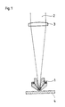
- FIG. 1 shows how, through a cutting nozzle 1 according to the invention, which is installed in a cutting head (not shown), the parallel laser beam 2 is initially focused onto the surface of the workpiece 4 to be cut with the aid of a focusing lens 3.
- the laser beam penetrates the nozzle channel for the cutting gas, which is arranged centrally in the cutting nozzle.
- Figure 2 shows the cutting nozzle of Figure 1 in an enlarged view.
- the cutting gas 5 flows through the central nozzle channel.
- a fuel gas-air or fuel gas-oxygen mixture 6 flows through the additional annular channel 7 and burns in the flame 8 after leaving the cutting nozzle.
- the combustion products form the hot gas curtain.
Abstract
Description
Die Erfindung betrifft ein verfahren zum Laserstrahlbrennschneiden eines Werkstückes mit einem fokussierten Laserstrahl und einem Schneidgasstrahl, die beide durch eine Schneiddüse geführt werden sowie eine Vorrichtung zur Durchführung des Verfahrens.The invention relates to a method for laser beam flame cutting of a workpiece with a focused laser beam and a cutting gas jet, both of which are guided through a cutting nozzle, and a device for carrying out the method.
Beim Laserstrahlbrennschneiden wird durch die Fokussierung eines Laserstrahls auf eine zu schneidende Werkstückoberfläche deren Erwärmung auf Zündtemperatur erreicht. Durch die Schneiddüse wird außer dem fokussierten Laserstrahl ein Schneidgasstrahl auf die Werkstückoberfläche geführt. Der Werkstoff verbrennt und es bildet sich eine Schnittfuge (H. Mair, "Thermische Schneidverfahren Autogenes Brennschneiden, Plasma-Schmelzschneiden, Laserstrahlschneiden - ein technologischer und wirtschaftlicher Vergleich", DVS-Berichte, Band 109, Deutscher Verlag für Schweißtechnik GmbH). Bei den bekannten Verfahren zum Laserstrahlbrennschneiden wird jedoch nicht immer, insbesondere bei größeren Materialdicken, die gewünschte optimale Schnittqualität erzielt.In laser beam flame cutting, the focusing of a laser beam on a workpiece surface to be cut achieves its heating to the ignition temperature. In addition to the focused laser beam, a cutting gas jet is guided through the cutting nozzle onto the workpiece surface. The material burns and a kerf is formed (H. Mair, "Thermal cutting processes oxy-fuel cutting, plasma fusion cutting, laser beam cutting - a technological and economic comparison", DVS reports, volume 109, German publisher for welding technology GmbH). In the known methods for laser beam flame cutting, however, the desired optimum cutting quality is not always achieved, in particular with larger material thicknesses.
Der Erfindung liegt deshalb die Aufgabe zugrunde, ein Verfahren und eine Vorrichtung der oben genannten Art aufzuzeigen, die eine Erhöhung der schneidbaren Materialdicke beim Laserstrahlbrennschneiden stärkerer Bleche gewährleisten und zu einer Verbesserung der Schnittqualität führen.The invention is therefore based on the object of demonstrating a method and a device of the type mentioned above, which ensure an increase in the material thickness that can be cut during laser beam flame cutting of thicker sheets and lead to an improvement in the cutting quality.
Diese Aufgabe wird erfindungsgemäß dadurch gelöst, daß der Schneidgasstrahl mit einem Gasschleier umhüllt wird.This object is achieved in that the cutting gas jet is enveloped with a gas curtain.
Das wesentliche Merkmal der Erfindung liegt darin, daß ein Gasschleier gleichsam wie ein Vorhang, ähnlich wie es beim autogenen Brennschneiden üblich ist, den Schneidgasstrahl umgibt. Der Gasschleier verhindert, indem er den Schneidgasstrahl vorhangartig umgibt, daß die Umgebungsluft aufgrund der sich durch die hohe Strömungsgeschwindigkeit des Schneidgasstrahles ergebenden Sogwirkung mitgerissen wird. Dadurch, daß wesentlich langsamer strömendes Gas oder Gasgemisch des Gasschleiers den bedeutend schneller strömenden Schneidgasstrahl umgibt, wird eine in etwa laminare Geschwindigkeitsverteilung der gesamten Gasströmung erzielt. Die Gasgeschwindigkeit nimmt stetig vom Zentrum des Schneidgasstrahles nach außen bis auf sehr geringe Geschwindigkeitswerte ab.The essential feature of the invention is that a gas curtain surrounds the cutting gas jet, as it were, like a curtain, similar to that which is customary in oxyacetylene cutting. By surrounding the cutting gas jet like a curtain, the gas curtain prevents the ambient air from being entrained due to the suction effect resulting from the high flow velocity of the cutting gas jet. The fact that gas or gas mixture of the gas curtain that flows at a much slower rate surrounds the cutting gas jet, which flows at a significantly faster rate, results in an approximately laminar velocity distribution of the entire gas flow. The gas speed decreases steadily from the center of the cutting gas jet to the outside to very low speed values.
Der Schneidgasstrahl wird folglich durch den Gasschleier stabilisiert. Er bleibt über eine längere Strecke (bis in die entstehende Schnittfuge im Werkstück) scharf gebündelt und weitet sich nicht auf. Das Brennschneiden von Blechen mit größerer Materialdicke wird so ermöglicht. Auch bringt dieses Verfahren eine wesentliche Verbesserung der Schnittqualität mit sich. Das Auswaschen der Schnittflächen sowie die Bildung von Kolkungen wird verhindert. Die Oxidation der Schnittflächen wird reduziert, so daß fast oxidfreie Schnitte erzielt werden können.The cutting gas jet is consequently stabilized by the gas curtain. It remains sharply bundled over a longer distance (up to the resulting kerf in the workpiece) and does not expand. This enables flame cutting of sheet metal with a larger material thickness. This process also brings about a significant improvement in the cut quality. Washing of the cut surfaces and the formation of scouring are prevented. The oxidation of the cut surfaces is reduced, so that almost oxide-free cuts can be achieved.
Ein besonders scharf gebündelter Schneidgasstrahl ergibt sich beim erfindungsgemäßen Verfahren dann, wenn das Schneidgas mit Überschallgeschwindigkeit die Schneiddüse verläßt.A particularly sharply focused cutting gas jet results in the method according to the invention when the cutting gas leaves the cutting nozzle at supersonic speed.
Der Gasschleier besteht bei einer vorteilhaften Ausführungsform des erfindungsgemäßen Verfahrens aus verbrannten Produkten eines Brenngas-Luft- oder Brenngas-Sauerstoff-Gemisches, die in einer weichen Flamme verbrennen. Die Flamme und damit der Gasschleier lassen sich hierbei einfach regeln.In an advantageous embodiment of the method according to the invention, the gas curtain consists of burned products of a fuel gas / air or fuel gas / oxygen mixture which burn in a soft flame. The flame and thus the gas curtain can be easily controlled.
Ein heißer Gasschleier bewirkt eine zusätzliche Erwärmung des Werkstückes in Schnittdickenrichtung. Dadurch wird die Aufhärtung in der entstehenden Schnittfuge verhindert.A hot gas curtain causes additional heating of the workpiece in the direction of the section thickness. This prevents hardening in the resulting kerf.
Im erfindungsgemäßen Verfahren eignen sich als Brenngase alle bekannten Brenngase, vorzugsweise werden Wasserstoff, Propan, Methan, Acetylen und/oder Etylen eingesetzt. Als Schneidgas wird vorzugsweise Sauerstoff mit einer Reinheit von mindestens 99,5 % verwendet.All known fuel gases are suitable as fuel gases in the process according to the invention, preferably hydrogen, propane, methane, acetylene and / or ethylene are used. Oxygen with a purity of at least 99.5% is preferably used as the cutting gas.
Eine andere Möglichkeit, einen heißen Gasschleier zu erzielen, besteht darin, daß Gas oder ein Gasgemisch auf elektrischem Wege oder indirekt durch den Laserstrahl erhitzt wird.Another way to achieve a hot gas curtain is to heat gas or a gas mixture electrically or indirectly through the laser beam.
In bestimmten Fällen kann es auch von Vorteil sein, wenn sich der Gasschleier aus kaltem Gas oder Gasgemisch zusammensetzt. Neben der Kühlung der Schneiddüse wird so erreicht, daß ein Wärmeverzug des zu schneidenden Werkstückes unterbunden wird. Dabei werden beispielsweise als Gas Stickstoff, Sauerstoff, Druckluft, Argon, Helium, CO₂ oder Gemische daraus eingesetzt.In certain cases it can also be advantageous if the gas curtain is composed of cold gas or a gas mixture. In addition to cooling the cutting nozzle, this ensures that heat distortion of the workpiece to be cut is prevented. For example, nitrogen, oxygen, compressed air, argon, helium, CO₂ or mixtures thereof are used as the gas.
Beim erfindungsgemäßen Verfahren wird mit Vorteil eine Schneiddüse eingesetzt, die neben der zentralen Düsenbohrung für das Schneidgas und den Laserstrahl einen oder mehrere zusätzliche Kanäle für das den Gasschleier bildende Gas oder Gasgemisch enthält. Verlaufen der oder die zusätzlichen Düsenkanäle für das den Gasschleier bildende Gas oder Gasgemisch koaxial zum Düsenkanal, ergibt sich ein zur Strömungsrichtung des Schneidgases symmetrischer, ringförmiger Gasschleier. Dabei können symmetrisch um den Düsenkanal für das Schneidgas angeordnet, ein einziger ringförmiger, zusätzlicher Düsenkanal oder, gleichfalls symmetrisch angeordnet, mehrere miteinander verbundene oder getrennt verlaufende, zusätzliche Einzelkanäle für das den Gasschleier bildende Gas oder Gasgemisch verwendet werden. Der oder die zusätzlichen Düsenkanäle werden spezifisch für die Art des verwendeten Gases oder Gasgemisches ausgelegt. Damit wird beispielsweise sichergestellt, daß sich bei der Verbrennung eines Brenngas-Luft- oder Brenngas-Sauerstoff-Gemisches eine stabilisierte Flamme ausbildet.In the method according to the invention, a cutting nozzle is advantageously used which, in addition to the central nozzle bore for the cutting gas and the laser beam, contains one or more additional channels for the gas or gas mixture forming the gas curtain. If the or the additional nozzle channels for the gas or gas mixture forming the gas curtain run coaxially to the nozzle channel, an annular gas curtain is obtained which is symmetrical to the flow direction of the cutting gas. It can be arranged symmetrically around the nozzle channel for the cutting gas, a single ring-shaped, additional nozzle channel or, likewise arranged symmetrically, a plurality of interconnected or separately running, additional individual channels can be used for the gas or gas mixture forming the gas curtain. The additional nozzle channel or channels are designed specifically for the type of gas or gas mixture used. This ensures, for example, that a stabilized flame forms during the combustion of a fuel gas-air or fuel gas-oxygen mixture.
Ein besonderer Vorteil der Erfindung liegt darin, daß, um sie anwenden zu können, lediglich die herkömmliche Schneiddüse einer Vorrichtung zum Laserstrahlbrennschneiden gegen eine erfindungsgemäße Schneiddüse mit einem oder mehreren zusätzlichen Düsenkanälen für das den Gasschleier bildende Gas oder Gasgemisch ausgetauscht werden muß.A particular advantage of the invention is that, in order to be able to use it, only the conventional cutting nozzle of a device for laser beam flame cutting has to be exchanged for a cutting nozzle according to the invention with one or more additional nozzle channels for the gas or gas mixture forming the gas curtain.
Die Erfindung sei im folgenden anhand eines Ausführungsbeispieles näher erläutert:
Hierbei zeigen:
- Figur 1
- den Strahlengang des Laserstrahls durch eine erfindungsgemäße Schneiddüse zur Werkstückoberfläche und
Figur 2- diese Schneiddüse vergrößert dargestellt.
Here show:
- Figure 1
- the beam path of the laser beam through a cutting nozzle according to the invention to the workpiece surface and
- Figure 2
- this cutting nozzle is shown enlarged.
In Figur 1 ist abgebildet, wie durch eine erfindungsgemäße Schneiddüse 1 hindurch, die in einem nicht dargestellten Schneidkopf eingebaut ist, der zunächst parallele Laserstrahl 2 mit Hilfe einer Fokussierlinse 3 auf die Oberfläche des zu schneidenden Werkstückes 4 gebündelt wird. Der Laserstrahl durchdringt hierbei den zentral in der Schneiddüse angeordneten Düsenkanal für das Schneidgas.FIG. 1 shows how, through a cutting nozzle 1 according to the invention, which is installed in a cutting head (not shown), the
Figur 2 zeigt die Schneiddüse aus Figur 1 in vergrößerter Darstellung.Figure 2 shows the cutting nozzle of Figure 1 in an enlarged view.
Das Schneidgas 5 strömt durch den zentralen Düsenkanal. Ein Brenngas-Luft- oder Brenngas-Sauerstoff-Gemisch 6 strömt durch den zusätzlichen ringförmigen Kanal 7 und verbrennt nach Verlassen der Schneiddüse in der Flamme 8. Die Verbrennungsprodukte bilden den heißen Gasschleier.The
Claims (7)
Applications Claiming Priority (2)
| Application Number | Priority Date | Filing Date | Title |
|---|---|---|---|
| DE4016181 | 1990-05-19 | ||
| DE4016181A DE4016181A1 (en) | 1990-05-19 | 1990-05-19 | METHOD AND DEVICE FOR LASER JET FLAME CUTTING |
Publications (3)
| Publication Number | Publication Date |
|---|---|
| EP0458182A2 true EP0458182A2 (en) | 1991-11-27 |
| EP0458182A3 EP0458182A3 (en) | 1993-09-15 |
| EP0458182B1 EP0458182B1 (en) | 1996-09-04 |
Family
ID=6406798
Family Applications (1)
| Application Number | Title | Priority Date | Filing Date |
|---|---|---|---|
| EP91107867A Expired - Lifetime EP0458182B1 (en) | 1990-05-19 | 1991-05-15 | Process and device for laser beam oxycutting |
Country Status (3)
| Country | Link |
|---|---|
| EP (1) | EP0458182B1 (en) |
| AT (1) | ATE142138T1 (en) |
| DE (2) | DE4016181A1 (en) |
Cited By (4)
| Publication number | Priority date | Publication date | Assignee | Title |
|---|---|---|---|---|
| WO1993009909A1 (en) * | 1991-11-19 | 1993-05-27 | Fraunhofer-Gesellschaft zur Förderung der angewandten Forschung e.V. | Method for removing material from moving metal workpieces |
| EP0628377A1 (en) * | 1993-06-14 | 1994-12-14 | L'air Liquide, Societe Anonyme Pour L'etude Et L'exploitation Des Procedes Georges Claude | Method for continuous laser CO2 welding of either alloyed or non-alloyed steels under protective gases |
| EP0647498A2 (en) * | 1993-10-08 | 1995-04-12 | Linde Aktiengesellschaft | Process for machining a workpiece, using laser beam with increase of the absorption grade of the workpiece surface |
| FR2743318A1 (en) * | 1996-01-04 | 1997-07-11 | Litech Sarl | LASER CUTTING METHOD AND DEVICE |
Families Citing this family (5)
| Publication number | Priority date | Publication date | Assignee | Title |
|---|---|---|---|---|
| DE4215561C2 (en) * | 1991-11-19 | 1995-04-06 | Fraunhofer Ges Forschung | Method and device for removing material from a relatively moving metal workpiece |
| DE4240190A1 (en) * | 1992-11-30 | 1994-06-01 | Linde Ag | Process for the machining of a workpiece by means of a laser beam and laser nozzle |
| DE4402000C2 (en) * | 1994-01-25 | 1996-04-11 | Fraunhofer Ges Forschung | Nozzle arrangement for laser beam cutting |
| DE10256779A1 (en) * | 2002-12-05 | 2004-06-24 | Messer Griesheim Gmbh | Shielding gas for electron beam welding in the atmosphere of metallic materials |
| RU2727392C1 (en) * | 2019-07-02 | 2020-07-21 | Федеральное государственное бюджетное образовательное учреждение высшего образования "Казанский национальный исследовательский технический университет им. А.Н. Туполева-КАИ" (КНИТУ-КАИ) | Optical head for laser cutting, welding |
Citations (3)
| Publication number | Priority date | Publication date | Assignee | Title |
|---|---|---|---|---|
| DE2658503A1 (en) * | 1976-01-09 | 1977-07-14 | Halle Feinmech Werke Veb | LASER CUTTING HEAD |
| GB2163692A (en) * | 1984-08-30 | 1986-03-05 | Ferranti Plc | Laser apparatus |
| EP0294324A1 (en) * | 1987-05-18 | 1988-12-07 | C.A. Weidmüller GmbH & Co. | Laser machining tool |
-
1990
- 1990-05-19 DE DE4016181A patent/DE4016181A1/en not_active Withdrawn
-
1991
- 1991-05-15 DE DE59108132T patent/DE59108132D1/en not_active Expired - Fee Related
- 1991-05-15 AT AT91107867T patent/ATE142138T1/en not_active IP Right Cessation
- 1991-05-15 EP EP91107867A patent/EP0458182B1/en not_active Expired - Lifetime
Patent Citations (3)
| Publication number | Priority date | Publication date | Assignee | Title |
|---|---|---|---|---|
| DE2658503A1 (en) * | 1976-01-09 | 1977-07-14 | Halle Feinmech Werke Veb | LASER CUTTING HEAD |
| GB2163692A (en) * | 1984-08-30 | 1986-03-05 | Ferranti Plc | Laser apparatus |
| EP0294324A1 (en) * | 1987-05-18 | 1988-12-07 | C.A. Weidmüller GmbH & Co. | Laser machining tool |
Non-Patent Citations (11)
| Title |
|---|
| DVS-BERICHTE Bd. 109, 1987, DüSSELDORF (DE) Seiten 188 - 199 H. MAIR ET AL. 'Thermisches Schneidverfahren Autogenes Brennschneiden, Plasma-Schmelzschneiden, Laserstrahlschneiden - ein technologisher und wirtschaftlicher Vergleich' * |
| OPTICS AND LASER TECHNOLOGY Bd. 6, Nr. 2, April 1974, HAYWARDS HEATH GB Seiten 78 - 81 W. W. DULEY ET AL. 'CO¥ laser cutting of thin metal sheets with gas jet assist' * |
| PATENT ABSTRACTS OF JAPAN vol. 10, no. 155 (M-485)(2211) 4. Juni 1986 & JP-A-61 009 990 ( MATSUSHITA DENKI SANGYO K.K. ) * |
| PATENT ABSTRACTS OF JAPAN vol. 10, no. 242 (M-509)(2298) 21. August 1986 & JP-A-61 074 795 ( MITSUBISHI ELECTRIC CORP ) 17. April 1986 * |
| PATENT ABSTRACTS OF JAPAN vol. 11, no. 74 (M-568)(2521) 6. März 1987 & JP-A-61 229 491 ( MITSUBISHI ELECTRIC CORP ) 13. Oktober 1986 * |
| PATENT ABSTRACTS OF JAPAN vol. 12, no. 109 (M-682)(2956) 8. April 1988 & JP-A-62 238 092 ( SONOYASU K.K. ) 19. Oktober 1987 * |
| PATENT ABSTRACTS OF JAPAN vol. 12, no. 18 (M-660)(2865) 20. Januar 1988 & JP-A-62 176 695 ( MATSUSHITA ELECTRIC IND CO LTD ) 3. August 1987 * |
| PATENT ABSTRACTS OF JAPAN vol. 12, no. 274 (M-725)(3121) 29. Juli 1988 & JP-A-63 056 389 ( AMADA CO LTD ) 10. März 1988 * |
| PATENT ABSTRACTS OF JAPAN vol. 7, no. 68 (M-201)(1213) 19. März 1983 & JP-A-57 209 792 ( MATSUSHITA DENKI SANGYO K.K. ) 23. Dezember 1982 * |
| PATENT ABSTRACTS OF JAPAN vol. 9, no. 187 (M-401)(1910) 3. August 1985 & JP-A-60 054 293 ( TOSHIBA K.K. ) 28. März 1985 * |
| PATENT ABSTRACTS OF JAPAN vol. 9, no. 319 (M-439)(2042) 14. Dezember 1985 & JP-A-60 154 894 ( MITSUBISHI DENKI K.K. ) 14. August 1985 * |
Cited By (9)
| Publication number | Priority date | Publication date | Assignee | Title |
|---|---|---|---|---|
| WO1993009909A1 (en) * | 1991-11-19 | 1993-05-27 | Fraunhofer-Gesellschaft zur Förderung der angewandten Forschung e.V. | Method for removing material from moving metal workpieces |
| US5651904A (en) * | 1991-11-19 | 1997-07-29 | Advanced Technik Gmbh | Method for removing material from metal workpieces moved relative to the removal tool |
| US5847358A (en) * | 1991-11-19 | 1998-12-08 | Advanced Technik Gmbh | Method and apparatus for removing material from metal workpieces moved relative to a laser removal tool |
| EP0628377A1 (en) * | 1993-06-14 | 1994-12-14 | L'air Liquide, Societe Anonyme Pour L'etude Et L'exploitation Des Procedes Georges Claude | Method for continuous laser CO2 welding of either alloyed or non-alloyed steels under protective gases |
| FR2706340A1 (en) * | 1993-06-14 | 1994-12-23 | Air Liquide | Welding process for alloyed or unalloyed steels by continuous laser with CO2 under shielding gas. |
| EP0647498A2 (en) * | 1993-10-08 | 1995-04-12 | Linde Aktiengesellschaft | Process for machining a workpiece, using laser beam with increase of the absorption grade of the workpiece surface |
| EP0647498A3 (en) * | 1993-10-08 | 1996-10-09 | Linde Ag | Process for machining a workpiece, using laser beam with increase of the absorption grade of the workpiece surface. |
| FR2743318A1 (en) * | 1996-01-04 | 1997-07-11 | Litech Sarl | LASER CUTTING METHOD AND DEVICE |
| WO1997025178A1 (en) * | 1996-01-04 | 1997-07-17 | Litech S.A.R.L. | Laser cutting method and device |
Also Published As
| Publication number | Publication date |
|---|---|
| EP0458182A3 (en) | 1993-09-15 |
| DE4016181A1 (en) | 1991-11-21 |
| EP0458182B1 (en) | 1996-09-04 |
| DE59108132D1 (en) | 1996-10-10 |
| ATE142138T1 (en) | 1996-09-15 |
Similar Documents
| Publication | Publication Date | Title |
|---|---|---|
| DE4226620C2 (en) | Process for laser beam cutting of strip or plate-shaped workpieces, in particular of electrical sheet | |
| DE3619513A1 (en) | METHOD FOR LASER CUTTING METAL WORKPIECES | |
| EP0017807B1 (en) | A process for reducing the build up of slag during flame cutting of metals and apparatus for carrying out the process | |
| DE2633719C2 (en) | Method for operating a cutting torch and nozzle for carrying out the method | |
| EP0458180A2 (en) | Process and device for laser beam cutting | |
| EP0458182A2 (en) | Process and device for laser beam oxycutting | |
| DE2841704C3 (en) | Method and device for thermochemical scarfing of a metallic workpiece | |
| EP0263469B1 (en) | Method for thermally coating surfaces | |
| DE4016412C2 (en) | ||
| EP1343607B1 (en) | Process gas and laser machining method | |
| DE19905739A1 (en) | Method and device for laser material processing with coaxial gas flow | |
| EP2134498B1 (en) | Method for autogenous processes | |
| DE3721685A1 (en) | BANDCASTING FLAME-CUTTING MACHINE IN CONTINUOUS CASTING PLANTS | |
| DE2948777A1 (en) | Autogenous flame cutting, esp. using oxy-acetylene - where air is added to heating flame to ensure adequate preheating of thick workpieces | |
| EP0121870A1 (en) | Method of and device for the thermal cutting of metallic materials | |
| EP3427886A1 (en) | Laser welding in reduced ambient pressure | |
| DE2519916C3 (en) | Method and device for increasing the cutting speed and improving the cutting quality during flame cutting by means of an oxygen jet | |
| EP0235588B1 (en) | Method for the removal of slag whiskers created by flame cutting | |
| DE19735354A1 (en) | Method for laser cutting or welding | |
| DE102018125607A1 (en) | Process for laser beam fusion cutting of a workpiece | |
| WO2002043917A1 (en) | Cutting gas and method for laser beam gas cutting | |
| DE4021412A1 (en) | Appts. for flame cutting - comprises multi-burner flame cutting machine with cutting table for underwater operation | |
| DE3842263C1 (en) | ||
| DD158933A1 (en) | METHOD FOR GENERATING A NATURAL GAS FLAME AS A TOOL | |
| DE2941764A1 (en) | Protective gas shield for multielectrode welding burner - where streams of gas prevent air entering gas nozzle, esp. when mfg. longitudinally seam welded tube |
Legal Events
| Date | Code | Title | Description |
|---|---|---|---|
| PUAI | Public reference made under article 153(3) epc to a published international application that has entered the european phase |
Free format text: ORIGINAL CODE: 0009012 |
|
| AK | Designated contracting states |
Kind code of ref document: A2 Designated state(s): AT BE CH DE FR LI NL |
|
| PUAL | Search report despatched |
Free format text: ORIGINAL CODE: 0009013 |
|
| AK | Designated contracting states |
Kind code of ref document: A3 Designated state(s): AT BE CH DE FR LI NL |
|
| 17P | Request for examination filed |
Effective date: 19931110 |
|
| 17Q | First examination report despatched |
Effective date: 19931223 |
|
| GRAG | Despatch of communication of intention to grant |
Free format text: ORIGINAL CODE: EPIDOS AGRA |
|
| GRAH | Despatch of communication of intention to grant a patent |
Free format text: ORIGINAL CODE: EPIDOS IGRA |
|
| GRAA | (expected) grant |
Free format text: ORIGINAL CODE: 0009210 |
|
| GRAH | Despatch of communication of intention to grant a patent |
Free format text: ORIGINAL CODE: EPIDOS IGRA |
|
| AK | Designated contracting states |
Kind code of ref document: B1 Designated state(s): AT BE CH DE FR LI NL |
|
| REF | Corresponds to: |
Ref document number: 142138 Country of ref document: AT Date of ref document: 19960915 Kind code of ref document: T |
|
| ET | Fr: translation filed | ||
| REF | Corresponds to: |
Ref document number: 59108132 Country of ref document: DE Date of ref document: 19961010 |
|
| PGFP | Annual fee paid to national office [announced via postgrant information from national office to epo] |
Ref country code: AT Payment date: 19970428 Year of fee payment: 7 |
|
| PGFP | Annual fee paid to national office [announced via postgrant information from national office to epo] |
Ref country code: FR Payment date: 19970513 Year of fee payment: 7 |
|
| PGFP | Annual fee paid to national office [announced via postgrant information from national office to epo] |
Ref country code: CH Payment date: 19970522 Year of fee payment: 7 |
|
| PGFP | Annual fee paid to national office [announced via postgrant information from national office to epo] |
Ref country code: NL Payment date: 19970529 Year of fee payment: 7 |
|
| PGFP | Annual fee paid to national office [announced via postgrant information from national office to epo] |
Ref country code: BE Payment date: 19970627 Year of fee payment: 7 |
|
| PLBE | No opposition filed within time limit |
Free format text: ORIGINAL CODE: 0009261 |
|
| STAA | Information on the status of an ep patent application or granted ep patent |
Free format text: STATUS: NO OPPOSITION FILED WITHIN TIME LIMIT |
|
| 26N | No opposition filed | ||
| PG25 | Lapsed in a contracting state [announced via postgrant information from national office to epo] |
Ref country code: AT Free format text: LAPSE BECAUSE OF NON-PAYMENT OF DUE FEES Effective date: 19980515 |
|
| PG25 | Lapsed in a contracting state [announced via postgrant information from national office to epo] |
Ref country code: LI Free format text: LAPSE BECAUSE OF NON-PAYMENT OF DUE FEES Effective date: 19980531 Ref country code: FR Free format text: LAPSE BECAUSE OF NON-PAYMENT OF DUE FEES Effective date: 19980531 Ref country code: CH Free format text: LAPSE BECAUSE OF NON-PAYMENT OF DUE FEES Effective date: 19980531 Ref country code: BE Free format text: LAPSE BECAUSE OF NON-PAYMENT OF DUE FEES Effective date: 19980531 |
|
| BERE | Be: lapsed |
Owner name: LINDE A.G. Effective date: 19980531 |
|
| PG25 | Lapsed in a contracting state [announced via postgrant information from national office to epo] |
Ref country code: NL Free format text: LAPSE BECAUSE OF NON-PAYMENT OF DUE FEES Effective date: 19981201 |
|
| REG | Reference to a national code |
Ref country code: CH Ref legal event code: PL |
|
| NLV4 | Nl: lapsed or anulled due to non-payment of the annual fee |
Effective date: 19981201 |
|
| REG | Reference to a national code |
Ref country code: FR Ref legal event code: ST |
|
| PGFP | Annual fee paid to national office [announced via postgrant information from national office to epo] |
Ref country code: DE Payment date: 19990624 Year of fee payment: 9 |
|
| PG25 | Lapsed in a contracting state [announced via postgrant information from national office to epo] |
Ref country code: DE Free format text: LAPSE BECAUSE OF NON-PAYMENT OF DUE FEES Effective date: 20010301 |