EP0458057A1 - Method for operating a vacuum cleaner - Google Patents
Method for operating a vacuum cleaner Download PDFInfo
- Publication number
- EP0458057A1 EP0458057A1 EP91105964A EP91105964A EP0458057A1 EP 0458057 A1 EP0458057 A1 EP 0458057A1 EP 91105964 A EP91105964 A EP 91105964A EP 91105964 A EP91105964 A EP 91105964A EP 0458057 A1 EP0458057 A1 EP 0458057A1
- Authority
- EP
- European Patent Office
- Prior art keywords
- vacuum cleaner
- motor
- nozzle
- cleaned
- fan motor
- Prior art date
- Legal status (The legal status is an assumption and is not a legal conclusion. Google has not performed a legal analysis and makes no representation as to the accuracy of the status listed.)
- Granted
Links
- 238000000034 method Methods 0.000 title description 13
- 238000004140 cleaning Methods 0.000 claims abstract description 154
- 230000003068 static effect Effects 0.000 claims abstract description 124
- 230000004044 response Effects 0.000 claims abstract description 32
- 238000001514 detection method Methods 0.000 claims abstract description 13
- 230000003044 adaptive effect Effects 0.000 claims description 8
- 239000000428 dust Substances 0.000 claims description 2
- 238000012545 processing Methods 0.000 description 107
- 238000010276 construction Methods 0.000 description 31
- 238000010586 diagram Methods 0.000 description 15
- 238000005259 measurement Methods 0.000 description 7
- 238000004804 winding Methods 0.000 description 5
- 238000002474 experimental method Methods 0.000 description 4
- 230000006870 function Effects 0.000 description 4
- 230000033001 locomotion Effects 0.000 description 3
- 208000027418 Wounds and injury Diseases 0.000 description 2
- 230000006378 damage Effects 0.000 description 2
- 208000014674 injury Diseases 0.000 description 2
- 238000005070 sampling Methods 0.000 description 2
- 230000007704 transition Effects 0.000 description 2
- 230000000052 comparative effect Effects 0.000 description 1
- 238000001816 cooling Methods 0.000 description 1
- 239000012530 fluid Substances 0.000 description 1
- 230000007274 generation of a signal involved in cell-cell signaling Effects 0.000 description 1
- 230000006698 induction Effects 0.000 description 1
- 238000009434 installation Methods 0.000 description 1
- 239000004065 semiconductor Substances 0.000 description 1
- 230000001360 synchronised effect Effects 0.000 description 1
Images









Classifications
-
- A—HUMAN NECESSITIES
- A47—FURNITURE; DOMESTIC ARTICLES OR APPLIANCES; COFFEE MILLS; SPICE MILLS; SUCTION CLEANERS IN GENERAL
- A47L—DOMESTIC WASHING OR CLEANING; SUCTION CLEANERS IN GENERAL
- A47L9/00—Details or accessories of suction cleaners, e.g. mechanical means for controlling the suction or for effecting pulsating action; Storing devices specially adapted to suction cleaners or parts thereof; Carrying-vehicles specially adapted for suction cleaners
- A47L9/28—Installation of the electric equipment, e.g. adaptation or attachment to the suction cleaner; Controlling suction cleaners by electric means
-
- A—HUMAN NECESSITIES
- A47—FURNITURE; DOMESTIC ARTICLES OR APPLIANCES; COFFEE MILLS; SPICE MILLS; SUCTION CLEANERS IN GENERAL
- A47L—DOMESTIC WASHING OR CLEANING; SUCTION CLEANERS IN GENERAL
- A47L9/00—Details or accessories of suction cleaners, e.g. mechanical means for controlling the suction or for effecting pulsating action; Storing devices specially adapted to suction cleaners or parts thereof; Carrying-vehicles specially adapted for suction cleaners
- A47L9/28—Installation of the electric equipment, e.g. adaptation or attachment to the suction cleaner; Controlling suction cleaners by electric means
- A47L9/2857—User input or output elements for control, e.g. buttons, switches or displays
-
- A—HUMAN NECESSITIES
- A47—FURNITURE; DOMESTIC ARTICLES OR APPLIANCES; COFFEE MILLS; SPICE MILLS; SUCTION CLEANERS IN GENERAL
- A47L—DOMESTIC WASHING OR CLEANING; SUCTION CLEANERS IN GENERAL
- A47L9/00—Details or accessories of suction cleaners, e.g. mechanical means for controlling the suction or for effecting pulsating action; Storing devices specially adapted to suction cleaners or parts thereof; Carrying-vehicles specially adapted for suction cleaners
- A47L9/28—Installation of the electric equipment, e.g. adaptation or attachment to the suction cleaner; Controlling suction cleaners by electric means
- A47L9/2805—Parameters or conditions being sensed
- A47L9/2821—Pressure, vacuum level or airflow
-
- A—HUMAN NECESSITIES
- A47—FURNITURE; DOMESTIC ARTICLES OR APPLIANCES; COFFEE MILLS; SPICE MILLS; SUCTION CLEANERS IN GENERAL
- A47L—DOMESTIC WASHING OR CLEANING; SUCTION CLEANERS IN GENERAL
- A47L9/00—Details or accessories of suction cleaners, e.g. mechanical means for controlling the suction or for effecting pulsating action; Storing devices specially adapted to suction cleaners or parts thereof; Carrying-vehicles specially adapted for suction cleaners
- A47L9/28—Installation of the electric equipment, e.g. adaptation or attachment to the suction cleaner; Controlling suction cleaners by electric means
- A47L9/2805—Parameters or conditions being sensed
- A47L9/2831—Motor parameters, e.g. motor load or speed
-
- A—HUMAN NECESSITIES
- A47—FURNITURE; DOMESTIC ARTICLES OR APPLIANCES; COFFEE MILLS; SPICE MILLS; SUCTION CLEANERS IN GENERAL
- A47L—DOMESTIC WASHING OR CLEANING; SUCTION CLEANERS IN GENERAL
- A47L9/00—Details or accessories of suction cleaners, e.g. mechanical means for controlling the suction or for effecting pulsating action; Storing devices specially adapted to suction cleaners or parts thereof; Carrying-vehicles specially adapted for suction cleaners
- A47L9/28—Installation of the electric equipment, e.g. adaptation or attachment to the suction cleaner; Controlling suction cleaners by electric means
- A47L9/2836—Installation of the electric equipment, e.g. adaptation or attachment to the suction cleaner; Controlling suction cleaners by electric means characterised by the parts which are controlled
- A47L9/2842—Suction motors or blowers
-
- A—HUMAN NECESSITIES
- A47—FURNITURE; DOMESTIC ARTICLES OR APPLIANCES; COFFEE MILLS; SPICE MILLS; SUCTION CLEANERS IN GENERAL
- A47L—DOMESTIC WASHING OR CLEANING; SUCTION CLEANERS IN GENERAL
- A47L9/00—Details or accessories of suction cleaners, e.g. mechanical means for controlling the suction or for effecting pulsating action; Storing devices specially adapted to suction cleaners or parts thereof; Carrying-vehicles specially adapted for suction cleaners
- A47L9/28—Installation of the electric equipment, e.g. adaptation or attachment to the suction cleaner; Controlling suction cleaners by electric means
- A47L9/2836—Installation of the electric equipment, e.g. adaptation or attachment to the suction cleaner; Controlling suction cleaners by electric means characterised by the parts which are controlled
- A47L9/2847—Surface treating elements
Definitions
- the present invention relates to a vacuum cleaner and more particularly to a vacuum cleaner having a power brush suction nozzle body in which the vacuum cleaner can be operated at the most optimum condition in response to a kind of a being surface to be cleaned and also a kind of a suction nozzle member.
- the vacuum cleaner comprises a vacuum cleaner main body and a power brush suction nozzle body having a rotary brush and being attached to the vacuum cleaner main body.
- the vacuum cleaner main body has a fan motor and the power brush suction nozzle body has a nozzle motor.
- the present invention relates to a vacuum cleaner having a control apparatus for a driving source of a vacuum cleaner main body and more particularly to a vacuum cleaner having a control apparatus for a fan motor such as a brushless motor being mounted on a vacuum cleaner main body.
- the suction nozzle member comprises a suction nozzle member for use in a general, a suction nozzle member for use in a shelf and a suction nozzle member for use in a crevice.
- the power for the power brush suction nozzle body is cut-off, the power brush suction nozzle body is used similar to as the general use suction nozzle member.
- the kind of the general use suction nozzle member including the case of the power for the power brush suction nozzle body being cut-off, the shelf use suction nozzle member and the crevice use suction nozzle member is judged according to the utilization of a static pressure of the vacuum cleaner.
- the power brush suction nozzle body is operated by judging the utilization of a fluctuation width of a current in the nozzle motor of the power brush suction nozzle body.
- the cleaning surface to be cleaned is detected in accordance with a variation a current which flows into a nozzle motor provided in a power brush suction nozzle body, and as a basis of this result an input of a fan motor is controlled.
- a voltage applied to AC commutator motor is adjusted by the triac, according to the cleaning surface to be cleaned or a detected value through the pressure sensor or the wind amount sensor, a power for the vacuum cleaner is controlled.
- An object of the present invention is to provide a vacuum cleaner wherein the most suitable suction force for the vacuum cleaner can be obtained automatically in response to a cleaning surface to be cleaned.
- Another object of the present invention is to provide a vacuum cleaner wherein the most suitable rotation speed for a rotary brush provided on a power brush suction nozzle body of the vacuum cleaner can be obtained automatically in response to a cleaning surface to be cleaned.
- a further object of the present invention is to provide a vacuum cleaner wherein a kind of a suction nozzle member can be discriminated automatically and thereby the most suitable suction force for the vacuum cleaner can be obtained automatically in response to kind of a cleaning surface to be cleaned and a kind of a suction nozzle member.
- a further object of the present invention is to provide a vacuum cleaner wherein various factors indicating a load condition of a fan motor of a vacuum cleaner main body such as a wind amount and a static pressure can be detected without any sensor mean and thereby an optimum operation for the vacuum cleaner can be obtained according to the detected factors indicating the load condition of the fan motor.
- a further object of the present invention is to provide a vacuum cleaner wherein the most suitable suction force for the vacuum cleaner can be obtained automatically in response to a cleaning surface to be cleaned even in a case of the cleaning surface to be cleaned is a tatami.
- the vacuum cleaner in a vacuum cleaner having a filter for catching dusts, a variable speed fan motor for giving a suction force to a vacuum cleaner, a pressure sensor provided within a vacuum cleaner main body and for detecting a clogging degree rate of the filter, and a circuit provided within the vacuum cleaner main body and for detecting a current of a rotary brush driving nozzle motor received in a power brush suction nozzle body, the vacuum cleaner is characterized in that, during a cleaning operation, using at least one selected from a fluctuation width of a peak value in the current of the nozzle motor and a fluctuation width of an output value of the pressure sensor a kind of a cleaning surface to be cleaned is estimated, using a rotation speed and a load current of the fan motor or an output of the pressure sensor and a rotation information about the fan motor a wind amount being flown into from a suction nozzle member is estimated, using the wind amount, a mean value of the output value of the pressure sensor and the current of the nozzle motor a kind of the
- the another cleaning surface to be cleaned can be estimated accurately.
- This cleaning surface to be cleaned estimation is carried out also in accordance with the size of the fluctuation of the static pressure being the output of the pressure sensor.
- the suction nozzle in use can classify the power brush suction nozzle or the other suction nozzle whether or not the current of the nozzle motor flows. Since the static pressure against the operation wind amount differs in each suction nozzle, the suction nozzle in use can be estimated by the static pressure at the operation wind amount.
- the rotation speed of the rotary brush is set at the optimum condition and further in response to the cleaning surface to be cleaned and the suction nozzle in use the fan motor is operated with the wind amount constant control, the static pressure constant control and the rotation speed, therefore the vacuum cleaner having the most suitable suction force can be obtained in response to the cleaning surface to be cleaned.
- the vacuum cleaner in a vacuum cleaner having a filter for catching dusts and a variable-speed fan motor for generating a dust suction force, the vacuum cleaner is characterized of providing a control apparatus in which in accordance with a current command and a speed command of the fan motor a wind amount or a static pressure being one of various factors for indicating a load condition of the vacuum cleaner is calculated, and in accordance with this calculation result of the wind amount or the static pressure the speed command of the fan motor is determined.
- the wind amount and the static pressure are calculated in accordance with the load current and the rotation speed of the fan motor and under a result of a speed command of the fan motor is determined, thereby without the pressure sensor or the wind amount sensor the most suitable suction force can be obtained in response to the load condition.
- a vacuum cleaner comprising a vacuum cleaner main body, a fan motor installed in the vacuum cleaner main body, a power brush suction nozzle body communicated to the vacuum cleaner main body and for contacting to a cleaning surface to be cleaned, a rotary brush installed in the power brush suction nozzle body, and a nozzle motor for driving the rotary brush, a filter for catching dusts in accordance with a rotation of the fan motor, the vacuum cleaner characterized an input adjusting means detects at least one of a mean value of a peak value and a fluctuation width of the peak value in a current flowing into the nozzle motor and adjusts automatically an input of the fan motor through the detection.
- the rotary brush Since the rotary brush contacts directly to the cleaning surface to be cleaned, during the cleaning operation, it causes the variation in the current of the nozzle motor for driving the rotary brush. Further, the fluctuation width of the peak value in the current of the nozzle motor can vary largely in response to the cleaning surface to be cleaned.
- the suction force suitable for the cleaning surface to be cleaned can be obtained.
- the cleaning surface to be cleaned can be judged accurately.
- a variable speed motor is described assuming a fan motor as a driving source of a vacuum cleaner.
- variable speed fan motor it is conceivable an AC commutator motor in which speed is varied by controlling an input, a phase control motor, an inverter-driven induction motor, a reactance motor, or a brushless motor.
- a brushless motor employed as the fan motor will be explained, such a brushless motor has a long life because that it has no brush being accompanied with a mechanical slide, and also the brushless motor has a good control responsibility.
- a nozzle motor for driving a rotary brush being mounted on a a power brush suction nozzle body is described assuming the nozzle motor.
- the nozzle motor it is conceivable a DC magnet motor or an AC commutator motor.
- an example of the employment of a rectifying circuit built-in type DC magnet motor for the nozzle motor will be explained.
- Fig. 1 is a block diagram showing a schematic construction of a control circuit
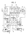
- Fig. 2 shows a whole construction of the control circuit.
- 16 indicates an inverter control apparatus.
- 29 indicates an AC power source, the current from AC power source 29 is rectified in a rectifying circuit 21, and smoothed in a condenser 22 and further supplied to a DC voltage E d to an inverter circuit 20.
- the inverter circuit 20 constitutes a 120° conductive type inverter comprising transistors TR1-TR6 and circulating diodes D1-D6 being connected in parallel to a respective transistor TR1-TR6.
- the transistors TR1-TR3 constitute positive arms.
- the transistors TR4-TR6 constitute negative arms.
- Each of period is pulse-width moderated (PWM) with an electric angle of 120°.
- R1 indicates a resistor having a comparative lower value which is connected to between an emitter side of the transistor TR4-TR6 constituting the negative arms and a minus side of the condenser 22.
- FM indicates a brushless motor for driving a fan (hereinafter called "fan motor"), and this fan motor FM has a rotor R comprised of a double pole permanent magnet and armature windings U, V and W.
- a load current I D flowing into the winding U, V or W is detected as a drop in voltage of the above resistor R1.
- a speed control circuit of the fan motor FM is constituted mainly of a magnet pole position detecting circuit 18 being detected by a Hall element 17 etc., a fan motor current detecting circuit 23 which detects the above load current I D and amplifies it, a base driver 15 for driving the above transistors TR1-TR6, and a microcomputer 19 for driving the base driver 15 in accordance with a detected signal 18S which is obtained from the above detecting circuit 18.
- 30 indicates an operation switch which is operated by an actual operator.
- 26 indicates a nozzle motor for driving a rotary brush which is provided in a power brush suction nozzle body side of a vacuum cleaner, and it is supplied an electric power according to a phase-controlling AC power source 29 by a triac (FLS) 25.
- 24 indicates a gate circuit of the triacs
- 27 indicates a current detector of a load current I N flowing to the nozzle motor
- 28 indicates a nozzle motor current detector for detecting and amplifying an output signal of the current detector 27.
- the magnetic pole position detecting circuit 18 receives from a signal from the Hall element 17 and the rotor R generates the magnetic pole position signal 18S.
- This magnetic pole position signal 18S is used for the current switching of the armature windings U, V and W also used as a signal for detecting a rotation speed of the fan motor FM.
- the microcomputer 19 requests the speed by counting a number of the magnetic pole position signal 18S within a predetermined sampling.
- the detecting circuit 23 for the load current I D of the fan motor FM obtains the load current I D of the fan motor FM by converting and amplifying the drop in voltage of the resistor R1 to a DC component through a peak hold circuit.
- the detecting circuit 28 for the load current I N of the nozzle motor 26 (in which the rectifying circuit is built-in) obtains the load current I N of the nozzle motor 26 by rectifying it and converting and amplifying an output signal of the current detector 27 to a DC component, because the output signal of the current detector 27 is the alternative current.
- the microcomputer 19 includes a central processing unit (CPU) 19-1, a read only memory (ROM) 19-2 and a random access memory (RAM) 19-3, and these are connected to each other by an address bass, a data bass and a control bass which are not shown.
- CPU central processing unit
- ROM read only memory
- RAM random access memory
- ROM 19-2 programmings necessary for driving the fan motor FM are stored, for example, which are an calculation processing of a speed, a take-in processing of an operation command, a speed control processing (ASR), a current control processing (ACR), a current detecting processing of the nozzle motor 26, a current detecting processing of the fan motor FM and a static pressure detecting processing etc..
- RAM 19-3 is used for reading and writing various outside data for practising the various programmings stored in the above ROM 19-2.
- the transistors TR1-TR6 are driven respectively by the base driver 15 in response to the gate signal 19S which is processed and generated in the microcomputer 19.
- the triac 25 is driven by the switching circuit 24 responding to the gate signal 19S which is processed and generated in the microcomputer 19 in accordance with a zero-cross detecting circuit 32 of AC power source 29.
- a static pressure detecting circuit 31 converts the output of a pressure sensor 8 provided in the vacuum cleaner main body to a static pressure.
- the output torque can be made variable by varying the supply current. Namely, by adjusting the supply current, the output torque of the fan motor FM can vary continuously and voluntarily. Further, according to changing a driving frequency of the inverter, the rotation speed of the fan motor FM can be varied freely.
- the above stated brushless type fan motor FM is used.
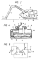
- Fig. 3 shows a whole construction of the vacuum cleaner and Fig. 4 shows an interior construction of the power brush suction nozzle body, respectively.
- 1 indicates a cleaning surface to be cleaned
- 2 a vacuum cleaner main body
- 3 a hose
- 4 a handy switching portion
- 5 an extension pipe
- 6 a rotary brush built-in type power brush suction nozzle body
- 7 a filter
- 8 the pressure sensor (a semiconductor pressure sensor) for detecting a clogging degree rate of the filter 7, respectively.
- a rotary brush 10 and brushes 11 attached to the rotary brush 10. 12 indicates a timing belt for transmitting a drive force of the nozzle motor 26 to the rotary brush 10. 13 indicates a suction extension pipe and 14 indicates rollers.
- a power source lead line 9 of the nozzle motor 26 is connected to a power source line 5A provided on the extension pipe 5.
- the rotary brush 10 rotates through the timing belt 12.
- the power brush suction nozzle body 6 contacts to the cleaning surface 1 to be cleaned. Since the brushes 11 are attached to the rotary brush 10, the brushes 11 contact to the cleaning surface 1 to be cleaned, thereby the load current I N of the nozzle motor 26 becomes large.
- Fig. 5 is a zero-cross detecting circuitry for phase-controlling of the nozzle motor 26 and Fig. 6 shows an electric power waveform and a current waveform applied to the nozzle motor 26, respectively.
- a zero-cross signal 32S shown in Fig. 6B is obtained through the zero-cross detecting circuit 32 which comprises a resistor R2, a diode D7, a photo-coupler PS and a resistor R3.
- the microcomputer 19 works to operates a count timer shown in Fig. 6C which is synchronized with the first transition and the last transition of the zero-cross signal 32S. When the count timer becomes zero, a gate signal 19D is outputted from the microcomputer 19 to FLS 25.
- the load current I N shown in Fig. 6A flows into the nozzle motor 26, by the phase control the rotation speed of the nozzle motor 26, in other words, the input is controlled.
- Figs. 7A - 7C shows a detecting circuit construction of the nozzle motor 26 and an example of the output thereof.
- a DC voltage signal V DP is obtained through a full wave rectification amplifying circuit 28, a diode D10 and a peak hold circuit 28B. During the suction nozzle operation this output signal V DP varies between V MX and V MN as shown in Fig. 7A.
- a voltage (V MX - V MN ) is made as a fluctuation width V MB of the detected voltage.
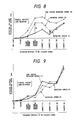
- Fig. 8 is a measurement result of a low speed rotation state of the nozzle motor 26 showing the fluctuation width V MB of the detected voltage corresponding to the variation of the load current I N of the nozzle motor 26 during the suction nozzle operation in response to the cleaning surface 1 to be cleaned.
- the rotation speed of the fan motor FM becomes large from the rotation speed (1) to the rotation speed (3) in turn, in other words, the suction force becomes large in turn.
- carpets from a carpet (1) to a carpet (6) indicate lengths of the carpet downs and are made longer in turn.
- Fig. 8 it may be considered whether or not the kind of the cleaning surface 1 to be cleaned can estimate in accordance with the fluctuation width V MB of the detected voltage.
- the fluctuation width V MB is zero in case of the floor and becomes large the tatami normal order, the tatami reverse order and the carpet in turn.
- the fluctuation width of the tatami reverse order is large that of the carpet (2).
- the fluctuation widths of the carpet (2) and the carpet (3) become similar to. Therefore, it is impossible to estimate the kind of the cleaning surface to be cleaned in accordance with merely the size of the fluctuation width V MB .
- the increasing rate A of the tatami reserve order is smaller than the increasing rate B of the carpet (2).
- the nozzle motor 26 rotates at a low speed at the start, in accordance with the size of the increasing rate between the fluctuation width V MB of the detected voltage and the increasing rate between of the rotation speed (1) and the rotation speed (2), it can distinguish or estimate the floor, the tatami, the carpet (1), the carpet (2) or the carpet (3) of the cleaning surface to be cleaned.
- Fig. 9 is a measurement result of a high speed rotation state of the nozzle motor 26 showing the fluctuation width V MB of the detected voltage corresponding to the variation of the load current I N of the nozzle motor 26 during the suction nozzle operation in response to the cleaning surface to be cleaned.
- the rotation speed of the rotary brush 10 is made less than 1200 rpm, so that it has the aims for no injury about the cleaning surface to be cleaned during the tatami and the floor and reduction in the noise.
- the rotation speed of the rotary brush 10 is made more than 2400 rpm, so that it can cope with the case of the carpet (the case may include the tatami).
- both the nozzle motor 26 and the fan motor FM are made low speed rotation, and when the suction nozzle operation is detected, the initial estimation of the cleaning surface to be cleaned is performed in accordance with the fluctuation width V MB of the detected voltage between the rotation speed (1) and the rotation speed (2) of the fan motor FM.
- the cleaning surface to be cleaned estimation makes the nozzle motor 26 at high speed rotation, the estimation of the cleaning surface to be cleaned is performed in accordance with the fluctuation width V MB of the detected voltage.
- the inputs of the fan motor FM and the nozzle motor 26 are controlled automatically.
- the cleaning surface to be cleaned estimation in accordance with the fluctuation width of the detected voltage which is a peak current value of the nozzle motor 26 is described in the above, next a method for the cleaning surface to be cleaned estimation (judgment) in accordance with the output of the pressure sensor provided in the vacuum cleaner main body will be explained.
- Fig. 10 is a measurement result showing the fluctuation width H MB of the static pressure (the fluctuation width of the detected voltage corresponding to the static pressure) in response to the cleaning surface to be cleaned against the rotation speed of the fan motor FM.
- the fluctuation width H MB of the static pressure has the largest value in comparison with that of the tatami. Accordingly, it is impossible to distinct the kind of the cleaning surface to be cleaned by the size of the fluctuation width H MB of the static pressure, because of the exsitence of the tatami reverse order.
- the cleaning surface to be cleaned is estimated in accordance with the fluctuation width H MB of the static pressure, it make to standardize the fluctuation width H MB of the static pressure during the suction nozzle operation at the rotation speed (1). And further, at the rotation speeds (2) and (3) more than the rotation speed (1), the fluctuation width H MB at of the tatami normal order is made as the threshold value.
- Fig. 11 shows an operation mode of the fan motor FM.
- the suction force p o of the vacuum cleaner is shown in the following formula and it is proportion to the product of the wind amount Q and the static pressure H. P o ⁇ Q ⁇ H (W)
- the constant wind amount Q makes always sure of the necessary minimum wind amount and static pressure of the suction nozzle portion.
- the static pressure becomes large in response to the clogging degree rate of the filter 7 (the rotation speed is made large in response to the clogging degree rate of the filter 7 and the constant wind amount Q is made constant, inversely the clogging degree rate can estimate according to the size of the static pressure).
- the constant static pressure H can mitigate the adhesion between the cleaning surface to be cleaned and the suction nozzle portion. For example, even the foreign matters attach to the suction nozzle, since the static pressure can rise as far as some degree, it is difficult to remove the foreign matters.
- the control values of the constant wind amount Q and the constant static pressure H are varied in response to the cleaning surface to be cleaned.
- the wind amounts Q1-Q5 and the static pressures H1-H5 correspond respectively to the cleaning surface to be cleaned, the carpet (1), the carpets (2) and (3) and the carpet (4) of the above stated cleaning surface to be cleaned estimation measurement results in accordance with the fluctuation widths of the peak values in the current of the nozzle motor 26 and the suction force is made large in order.
- the constant wind amount Q and the constant static pressure H can set to be Q2, H2 and Q4, H4 in Fig. 11 respectively.
- the static pressure H it can employ the output of the pressure sensor 8, however with respect to the wind amount Q it is requested in accordance with the calculation.
- it is suitable to adopt methods that use of the current and the rotation speed of the fan motor FM or use of the static pressure and the rotation speed of the fan motor FM, it is not limited to the rotation speed itself but it may adopt an information corresponding to the rotation speed.
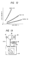
- Fig. 12 is a measurement result showing a relation between the wind amount and the static pressure about the suction nozzle for crevice use, the suction nozzle for shelf use and the suction nozzle for general use, each of suction nozzle members is a representative one.
- the power brush suction nozzle body is included.
- the distinction between the power brush suction nozzle body and other suction nozzles is performed as following.
- step 1 When the operation switch 30 becomes "on" condition, an operation command take-in processing and a starting processing (processing 7) are carried out, and the rotation speed of the fan motor FM is risen up to the rotation speed (1) of a standby state.
- step 2 The rotation speed N is calculated in accordance with the receipt of the signal 18S from the magnetic pole position detecting circuit 18 (processing 1), the wind amount Q is calculated in accordance with the calculation of the current command I* (correspond to the load current) of the fan motor FM (processing 12).
- a static pressure detecting processing (processing 13) is carried out and thereby the static pressure H is detected.
- the nozzle motor 26 receives the signal from the zero-cross detecting circuit 32 and to which the instantaneous current is applied, and in accordance with the receipt of the signal 24S from the nozzle motor current detecting circuit 24, thereby the nozzle motor current detecting processing (processing 2) is carried out.
- suction nozzle judgment processing when the nozzle motor current is detected it is judged as the power brush suction nozzle body, and when the current is not detected it is judged as other suction nozzle.
- step 3 A clogging degree rate detecting processing of the filter 7 (processing 5) is carried out in accordance with the relation between the static pressure H against the wind amount Q, and thereby the clogging degree rate of the filter 7 is detected.
- step 4 In the suction nozzle judgment (processing 4), when it is the power brush suction nozzle body, the nozzle motor 26 is driven (at low rotation speed) through the zero-cross detecting circuit 32, a phase control angle setting processing (processing 8) and a gate signal processing (processing 9), and thereby at the time of the suction nozzle operation period the fluctuation width of the peak value in the current of the nozzle motor 26, the fluctuation width of the static pressure H and the clogging degree rate of the filter 7 are detected.
- step 5 At the stage in which the first time cleaning surface to be cleaned estimation is finished, the fan motor 26 is risen up to the rotation speed (2), and the cleaning surface to be cleaned estimation (processing 4) is carried out under the consideration of the increasing rate between the fluctuation width of the peak value in the current of the nozzle motor 26 and the rotation speed (1), the increasing rate between the fluctuation width of the static pressure H and the rotation speed (1), and the clogging degree rate of the filter 7.
- step 6 In accordance with the result of the cleaning surface to be cleaned estimation (processing 4) in the step 4, in an adaptive control model 19A, the wind amount (Q1-Q5), the static pressure (H1-H5) and the rotation speed N are set respectively and by changing-over these values a speed command N* is outputted.
- the fan motor current detecting processing (processing 3) is carried out and the load current I D of the fan motor FM is detected.
- a current command I* are outputted from the processing 11 of the speed control processing (ASR) and the current control processing (ACR).
- a base driver signal 19S is outputted and thereby the fan motor FM is controlled at a desired rotation speed.
- step 7 Simultaneously, in accordance with the result of the cleaning surface to be cleaned estimation (processing 4), by receiving the signal from the zero-cross detecting circuit 32 the gate angle is determined in the gate signal generating processing (processing 9).
- the gate signal 19A of FLS 25 for the nozzle motor 26 is outputted through the gate signal generating processing (processing 9) and the nozzle motor 26 is controlled at a desired rotation speed.
- step 8 When the result of the cleaning surface to be cleaned estimation (processing 4) is the floor, the nozzle motor 26 is rotated at a slow rotation speed. And utilizing the data of two rotation speeds comprising of the rotation speed (1) of the fan motor FM and the actual rotation speed, this method for the cleaning surface to be cleaned estimation of the step 5 is carried out repeatedly.
- step 9 When the result of the cleaning surface to be cleaned estimation (processing 4) is the tatami or the carpet, the nozzle motor 26 is rotated at a high rotation speed.
- step 10 In the suction nozzle judging processing (processing 4) in the step 2, when it is judged as the general use suction nozzle, as under the standard of the rotation speed (1) of the fan motor FM, and taking into the consideration of the increasing rate between the fluctuation width of the static pressure H under the actual rotation speed and the fluctuation width of the static pressure H under the rotation speed (1) and the clogging degree rate of the filter 7, the cleaning surface cleaned is distinguished or estimated as the kind comprising of the floor and the tatami or as the kind of comprising the carpet.
- step 11 When the cleaning surface to be cleaned is estimated as the kind comprising of the floor and the tatami in the step 10, in the adaptive control model 19A, for example, the speed command N* is outputted corresponding to the wind amount Q2, the static pressure H2 and the rotation speed N.
- step 12 When the cleaning surface to be cleaned is estimated as the kind comprising of the carpet in the step 10, in the adaptive control model 19A, for example, the speed command N* is outputted corresponding to the wind amount Q2, the static pressure H2 and the rotation speed N.
- step 13 In the suction nozzle judging processing (processing 14) in the step 2, when it is judged as the shelf use suction nozzle or the crevice use suction nozzle, in the adaptive control model 19A, the speed command N* is outputted corresponding to one wind amount Q and one static pressure H or the speed command N* is outputted corresponding to two wind amounts Q and two static pressures H.
- the rotary brush 10 rotates at the low rotation speed, however it may step the rotation of the rotary brush 10 and may rotate again according to the size of the fluctuation width of the static pressure H.
- the microcomputer 19 may install the driving soft for the fan motor FM or the driving soft for the fan motor FM and the nozzle motor 26, and it may install the soft for the suction nozzle estimation and the cleaning surface to be cleaned estimation in another microcomputer.
- the rotation speed and the load current are adopted, however it may adopt the static pressure and the rotation information (for example, the phase control angle in a case that employment of AC commutator motor as the fan motor FM).
- the clogging degree rate of the filter 7, the kind of the suction nozzle in use and the kind of the cleaning surface to be cleaned are detected automatically and in accordance with this detection the fan motor FM and the nozzle motor 26, thereby the vacuum cleaner having a good clogging degree rate of the filter 7, the suction nozzle in use and the most suitable suction port according to the cleaning surface to be cleaned can be obtained automatically.
- FIG. 13 is a schematic construction showing a fan motor for use in the vacuum cleaner according to one embodiment of the present invention.
- a fan motor comprises a variable speed motor 38 and a fan 39, by receiving a signal 41S from a speed detector 41 and a signal 42S from a current detector 42, a rotation speed and a load current are detected in a control apparatus 40.
- a control apparatus for controlling the variable speed motor 38 calculates various factor indicating a load condition from the rotation speed and the load current, for example a wind amount Q and a static pressure H, and under the calculation result the fan motor 38 is operated.
- the fan motor 38 there are considered the uses for an electric fan, a blower for cooling or a vacuum cleaner etc.. In this embodiment, it will be explained as an example about the fan motor for use in the vacuum cleaner in which an operation condition is varied according to the load condition.
- Fig. 14 is a block diagram showing a schematic construction of the control circuit
- Fig. 15 is a whole construction of the control circuit.
- 16 indicates an inverter control apparatus for variable speed operation of a brushless motor 17.
- 29 indicates an AC power source, this power source 29 is rectified by a rectifying circuit 21 and smoothed in a condenser 22 and a DC voltage E d is supplied to an inverter circuit 20.
- this kind brushless motor 17 since the current flowing into the armature windings U, V and W corresponds to an output torque of the motor 17, inversely the output torque can be varied according to varying the applied current. Namely, by adjusting the applied current the output torque of the motor 17 can be varied continuously and voluntarily, and by varying the drive frequency of the inverter the rotation speed of the motor 17 can be varied voluntarily. In the vacuum cleaner of the present invention, this kind brushless motor 17 can adopt.
- Fig. 16 shows a Q-H characteristic of the vacuum cleaner using the brushless motor 17, the wind amount Q is shown in the horizontal axis and the static pressure H and the load torque T of the fan (the fan of the blower motor in the vacuum cleaner) are shown in the vertical axis.
- L is a shaft input (W) of the fan
- Q is the wind amount (m3/min)
- H is the static pressure (mmAq)
- N F is the rotation speed of the fan
- D is the diameter (mm) of the runner of the fan. Since the fan and the brushless motor 17 are coupled directly, it is considered that the shaft input L and the rotation speed N F of the fan are equal to the output P and the rotation speed N of the brushless motor 17, respectively.
- the above formula (4) is transformed to the next formula according to the above formula (5) and the above stated formula (6).
- P is the output (W) of the brushless motor 17 and N is the motor rotation speed (rpm).
- E0 is the induced voltage (V)
- K ⁇ is the coefficient of the induced voltage
- I is the load current (A).
- the wind amount Q is expressed as following by the above formula (7), the above formula (8) and the above formula (9).
- K is the proportional coefficient.
- This proportional coefficient K includes many error factors such as the blower efficiency, the motor efficiency, the air leakage from the vacuum cleaner main body and the unit volume weight variety of air due to temperature, however in this case it takes constant.
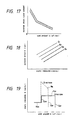
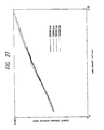
- Fig. 17 shows the wind amount Q at the horizontal axis and the ratio (rotation speed / load current) of the rotation speed N and the load current I of the brushless motor 17 at the vertical axis.
- the wind amount Q is calculated from the value of the rotation speed / the load current.
- Fig. 18 is a H-N characteristic for each of the wind amounts Q1-Q4 in a case that the static pressure H is shown at the horizontal axis and the rotation speed N is shown at the vertical axis. From this figure, the static pressure H is requested in accordance with the relation of the following formula. N ⁇ Q ⁇ (aH + b) (11)
- a is constant and b is constant.
- the wind amount Q and the static pressure H for the vacuum cleaner can be calculated in accordance with the load current I and the rotation speed N of the brushless motor 17.
- Fig. 19 shows the representative operation patterns ( A pattern and B pattern) of the vacuum cleaner.
- a pattern shows that the wind amount Q A1 constant control is practised at the large wind amount side and, at less than the wind amount Q A1 side the static pressure H A1 constant control, the wind amount Q AB constant control and the static pressure H AB constant control are practised.
- a pattern assumes the cleaning surface to be cleaned in a case of the tatami, in which the rotation speed is reduced at more than the large wind amount Q A1 and the motor input is squeezed to be the constant wind amount Q A1 and, similar to under less than the small wind amount Q AB the rotation speed is reduced and the motor input is squeezed to be the constant wind amount Q AB .
- the static pressure H A1 constant control is practised, and under less than the wind amount Q AB and less than the static pressure H AB , the static pressure H AB constant control is practised.
- the microcomputer 19 When the actual operator operates the operation switch, first of all the microcomputer 19 carries out the operation command take-in processing and the starting processing in the processing 1 and drives the brushless motor 17 to the prescribed rotation speed N1.
- the changing-over switch S1 selects the speed command N1 during the starting and when the starting is completed the output N CMD of AQR (wind amount regulator) and AHR (static pressure regulator) in the processing is selected.
- the microcomputer 19 receives the magnetic pole position signal 18S from the magnetic pole position detecting circuit 18 and carries out the gate signal generation processing in the processing 6 and the gate element of the transistors TR1-TR6 is determined.
- the actual speed of the brushless motor 17 is calculated and in the current detecting processing of the processing 3 by receiving the signal from the current amplifier 23 the load current I L of the brushless motor 17 is detected.
- the current command I CMD is requested from the deviation ⁇ N between the speed command N* and the actual rotation speed N.
- the voltage command V* is calculated from the deviation ⁇ I between the current command I CMD and the load current I L .
- the gate signal generating processing in the processing 6 by receiving the voltage command V* and the magnetic pole position signal 18S the element for gating the transistors TR1-TR6 is determined and a PWM signal 19S for varying the applied voltage is outputted.
- AQR wind amount regulator
- AHR static pressure regulator
- the brushless motor 17 determines the voltage V* and controls through ASR and ACR in the processings 4 and 5.
- the brushless motor 17 is used as the drive source of the vacuum cleaner, without use of the pressure sensor and the wind amount sensor. Further, the wind amount Q and the static pressure H are calculated in accordance with the load current I L and the rotation speed N of the brushless motor 17, and the wind amount constant control (AQR) and the static pressure constant control (AHR) are operated according to the respective operation pattern, thereby it can control the optimum power for the vacuum cleaner.
- the wind amount constant control (AQR) and the static pressure constant control (AHR) are operated according to the respective operation pattern, thereby it can control the optimum power for the vacuum cleaner.
- the calculation for the wind amount Q and the static pressure H is calculated in accordance with the rotation speed and the load current of the brushless motor 17, it may be calculated in accordance with the ratio between the rotation speed and the current command.
- the calculation values of the wind amount Q and the static pressure H are used for controlling the brushless motor 17, however it may use for indicating the load condition of the vacuum cleaner.
- the example in the use of the brushless motor 17 as the fan motor for use in the vacuum cleaner is explained, however it may adopt an AC commutator motor.
- Fig. 20 - Fig. 26 are another embodiment according to the present invention.
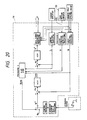
- Fig. 20 is a block diagram showing a schematic construction of a control circuit using a static pressure H together
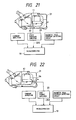
- Fig. 21 is a schematic construction of a static pressure detection of the vacuum cleaner.
- the static pressure H of the vacuum cleaner 31 is detected by a static pressure sensor 32.
- the static pressure is detected by the static pressure sensor 32 mounted on the vacuum cleaner 31, in the static pressure processing in the processing 8 included in the microcomputer 19 and by receiving a signal 33S from a static pressure amplifier 33, the static pressure H of the vacuum cleaner 31 is detected.
- the wind amount Q is calculated in accordance with the rotation speed N and the load current I L , and in AHR (static pressure regulator) using the detected static pressure H it may output the speed command N CMD so as to be become a predetermined wind amount Q and a predetermined static pressure H, respectively, for example to be become A pattern and B pattern in Fig. 19.
- Fig. 22 is a schematic construction of a wind amount detection of the vacuum cleaner
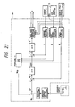
- Fig. 23 is a schematic construction of a control circuit using a wind amount sensor together.
- Fig. 23 the following points differ in comparison with Fig. 14.
- the wind amount of the vacuum cleaner 31 is detected.
- the wind amount is detected by a wind amount sensor 34 mounted on the vacuum cleaner 31, and in the wind amount processing in the processing 10 included in the microcomputer 19 and by receiving a signal 35S from an wind amount amplifier 35, the wind amount Q of the vacuum cleaner 31 is detected.
- Fig. 24 is a block diagram showing a schematic construction of a control circuit using a rotation speed N and a DC voltage E d of the brushless motor 17
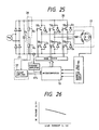
- Fig. 25 is a whole construction of the control circuit
- Fig. 26 is a plotting curve showing a drooping characteristic of DC voltage E d of the brushless motor 17 according to the load current I L in which the load current I L is shown at the horizontal axis and DC voltage E d is shown at the vertical axis.
- the wind amount Q is calculated in accordance with the load current calculation value calculated from the rotation speed N.
- AHR static pressure regulator
- the static pressure H is calculated in accordance with the calculated wind amount Q and the rotation speed N, and it can output the speed command N CMD so as to become a predetermined wind amount Q and a predetermined static pressure H, respectively, for example to be become A pattern and B pattern shown in Fig. 19.
- the brushless motor 17 as the driving source of the vacuum cleaner 31, and in accordance with use of one of the sensor of the pressure sensor or the static pressure sensor and further the load current I L and the rotation speed N of the brushless motor 17, the wind amount Q or the static pressure H is calculated, and according to the operation pattern and the wind amount constant control (AQR) and the static pressure constant control (AHR) are operated, thereby it can control the optimum power for the vacuum cleaner 31.
- the wind amount Q or the static pressure H is calculated by the calculation, and according to the operation pattern and the wind amount constant control (AQR) and the static pressure constant control (AHR) are operated, thereby it can control the optimum power for the vacuum cleaner.
- the various factors for indicating the load condition of the fan motor for use in the vacuum cleaner namely the wind amount Q and the static pressure H are calculated in accordance with the relation between the rotation speed N and the load current I L of the brushless motor 17, under the calculation result since the rotation speed of the fan motor is adjusted, thereby the control apparatus of the fan motor being operable at the optimum power for use in the vacuum cleaner can be obtained.
- Fig. 29 and Fig. 30 of this embodiment same numeral indicates the same or the substantial corresponding element shown in Fig. 1 and Fig. 2.
- a function table is used in the processing 6.
- the pressure sensor 8 and the static pressure detecting circuit 31 shown in Fig. 1 are not mounted on respectively.
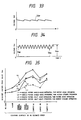
- Figs. 31A and 31B show voltages applied to the nozzle motor 26 and a current waveform.
- a peak value in the current of the nozzle motor 26 varies largely.
- the deviation ⁇ I N (I N2 - I N1 ) causes in the nozzle motor current in a case whether or not the suction nozzle contacts against the cleaning surface to be cleaned.
- Figs. 31A and 31B show a circuit construction of the amplifier and Figs. 32A and 32B show an example of an output of the amplifier.
- Fig. 31A as an example for the amplifier 28, it comprises an amplifying element 32, a rectifying circuit 31 and a peak hold circuit 33.
- the operation of this amplifier 28 is as follows. When the nozzle motor current I N flows into the nozzle motor 26, a voltage waveform appears at both ends of the resistor R2, which is connected to a current detector 27, corresponding to the nozzle motor current I N .
- This voltage waveform is amplified through the amplifying element 32, the peak value of the nozzle motor current I N is converted to the direct current part through the rectifying circuit 31 and the peak hold circuit 33 and is inputted into the microcomputer 19.
- the output of the peak hold circuit 33 as shown in Figs. 32A and 32B, becomes a direct current voltage V DP corresponding the peak value of the nozzle motor current I N .
- Fig. 31B shows another embodiment of the amplifier 28, it comprises a whole wave amplifying circuit having two operable amplifiers.
- the output V DP of this becomes a result similar to that of Fig. 31A.
- Fig. 34 shows a detected voltage V DP in response to the variation in a load current of the nozzle motor 26 during the power brush suction nozzle body operation.
- the detected voltage V DP in response to the peak value in the load current I N is varied between V MN and V MX .
- V MD is mean value between the detected voltages V MN and V MX .
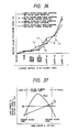
- Fig. 35 shows a measurement result of the variation in the mean value of the detected voltage V MD in response to the cleaning surface to be cleaned.
- (1) indicates that the nozzle motor 26 is operated with a whole-wave operation (the voltage rectified the alternative power source 29 with the whole-wave is applied to the nozzle motor 26 and the vacuum cleaner operated with the full power) and the fan motor FM such as a brushless motor is operated with the weak operation
- (2) indicates that the nozzle motor 26 is operated with the whole-wave operation and the fan motor FM is operated with the strong operation
- (3) indicates that the nozzle motor 26 is operated with a half-wave operation (the voltage rectified the alternative power source 29 with the half-wave is applied to the nozzle motor 26 and the vacuum cleaner operated with the half power) and the fan motor FM is operated with the weak operation
- (4) indicates that the nozzle motor 26 is operated with the half-wave operation and the fan motor FM is operated with the strong operation.
- the mean value V MD of the detected value is made to larger in sequence the floor, the tatami and the carpet.
- the tatami shows that the suction nozzle is operated in parallel with the rush arranging direction (the tatami normal order) and the tatami shows that the power brush suction nozzle body is operated in orthogonal with the rush arranging direction (the tatami reverse order).
- Each of the numbers (a)-(c) indicates the length of the downs and it is formed to be longer in sequence from (a) to (c) in the carpet.
- the cleaning surface to be cleaned is judged only in accordance with the mean value V MD of the detected voltage
- the mean value V MD varies in accordance with the operation conditions of the nozzle motor 26 and the fan motor FM
- the mean value V MD is substantially same in the case of the tatami of the tatami reverse order surface and in the case of the carpet, and further the mean value V MD does not vary corresponding to the length of the downs of the carpet.
- Fig. 36 shows a measurement result of the variation of the fluctuation width V MB (V MX - V MN ) of the detected voltage in response to the cleaning surface to be cleaned, in which the numbers (1)-(4) are same conditions shown in Fig. 35.
- the fluctuation width V MB of the detected voltage is not affected the operation conditions of the nozzle motor 26 and the fan motor FM. In the case of the no load, the fluctuation width V MB of the detected voltage becomes zero.
- the normal order or the reverse order of the tatami surface, the fluctuation widths V MB of the detected voltage with respect to the cleaning surface to be cleaned are made larger in sequence the floor, the tatami and the carpet. Further it can discriminate the tatami and the carpet and the fluctuation width is made larger in sequence the lengths of the downs (a)-(c) in the carpet.
- the fluctuation widths V MB of the detected voltage is substantially same between the floor and the tatami of the cleaning surface to be cleaned, only by using the fluctuation width V MB , it is difficult to judge the cleaning surface to be cleaned whether the floor or the tatami.
- the judgment about the cleaning surface to be cleaned whether the floor or the tatami by using the mean value V MD of the detected voltage shown in Fig. 35, can be judged under in addition to the operation conditions of the nozzle motor 26 and the fan motor FM.
- Fig. 37 shows the characteristic of the vacuum cleaner.
- the horizontal axis shows the wind amount Q (m3/min) and the vertical axis shows the suction power P OUT indicating the suction performance, the rotation speed N of the fan motor FM and the load current I D .
- An area sandwitched between two of two-dots chain lines is the actual operation range.
- the wind amount exists in the maximum operation point, in proportional to the proceeding of the clogging of the filter, the operation point transfers gradually toward the left side, and when it becomes completely the filter clogging condition the wind amount reaches to the minimum operation point.
- the mean value V MD of the detected voltage V DP receives the affect according to the above stated operation condition of the vacuum cleaner and this relates also the clogging of the filter of the vacuum cleaner. Namely, when the filter is not clogged, since the wind amount is large the suction force becomes strong.
- the load current I D of the fan motor FM has the close relation to the wind amount. Accordingly, by detecting the load current I D of the fan motor FM the clogging degree rate of the filter is judged, and then the standard for judging the cleaning surface to be cleaned according to the variation of the load current of the nozzle motor 26 can be corrected.
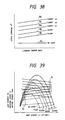
- Fig. 38 shows a control pattern stored in ROM 19-2 of the microcomputer 19, concretely it is indicated as the function table 8 which corresponds to the respective cleaning surface to be cleaned.
- the horizontal axis shows the clogging degree rate of the filter and the vertical axis shows the speed command N*.
- the rotation speed command is made large in sequence the no load, the floor, the tatami, the carpet (a), the carpet (b) and the carpet (c), and it is set to increase the rotation speed in proportional to the proceeding degree of the clogging degree rate of the filter. According to the above means, the speed command in response to the clogging degree rate of the filter and the cleaning surface to be cleaned can be obtained, and therefore the optimum control for the vacuum cleaner can be attained.
- step 1 When the operation switch 30 enters to "on" condition, the operation command take-in processing and the starting processing (processing 7) are carried out and thereby the operation is prepared.
- step 2 From the function table 8 the speed command N o on the no load is outputted, under the results of the speed calculation (processing 1) and the current detection (processing 3), the current command I* is calculated by carrying out the speed control and the current control processing (processing 9).
- the transistor necessary to gate within the transistors TR1-TR6 and the current factor thereof are determined according to the gate signal generating processing (processing 10) and the fan motor FM is risen up to the rotation speed N o .
- This series of the processings is called as for short, hereinafter, a motor control processing.
- step 3 The nozzle motor 26 selects the operation mode (1) of the weak rotation and is rotated by carrying out the gate signal generating processing (processing 9). The nozzle motor 26 is risen up to the rotation speed necessary to judge the cleaning surface to be cleaned.
- step 4 The current detecting processing (processing 2) of the nozzle motor 26 is carried out. And according to the mean value V MD within the predetermined sampling period and the fluctuation width V MB (V MX - V MN ) of the load current the judging processing (processing 4) of the cleaning surface to be cleaned is carried out and thereby the cleaning surface to be cleaned is estimated.
- step 5 Under the above estimation result of the cleaning surface to be cleaned the speed command N1-N5 in response to the respective cleaning surface to be cleaned is selected, thereby the motor control processing is carried out.
- step 6 The load current I D of the fan motor FM which motions under the rotation speed suitable for the respective cleaning surface to be cleaned is detected by the current detecting processing (processing 4). Under the detected value the filter clogging degree rate judging processing (processing 5) is carried out, and thereby the rotation speed command of the fan motor FM is corrected in response to the filter clogging degree rate.
- step 7 by adding the clogging degree rate of the filter, the judging processing (processing 4) of the cleaning surface to be cleaned is carried out again. Under the estimation result about the cleaning surface to be cleaned the speed command N1-N5 is selected.
- the operation mode of the nozzle motor 26 is set to be the mode (1) (processing 8) of the weak rotation speed, and when it is carpet the operation mode of the nozzle motor 26 is set to be the mode (2) (processing 8) of the strong rotation speed, respectively.
- the cleaning surface to be cleaned is estimated or judged in accordance with the variation of the load current I N of the nozzle motor 26, under the result the motion rotation speeds of the nozzle motor 26 and the fan motor FM can be set.
- the vacuum cleaner being controlled at the most suitable in response to the respective cleaning surface to be cleaned can be obtained.
- Fig. 40 shows the variation of the load current during the suction nozzle operation in which the nozzle motor 26 rotates at the low speed rotation.
- the nozzle motor 26 rotates at the low speed rotation, there does not make much difference the mean value and the fluctuation width of the load current against the respective cleaning surface to be cleaned.
- the kind of the cleaning surface to be cleaned is estimated in accordance with the mean value of the fluctuation width of the peak value in the current of the nozzle motor 26, even when the cleaning surface to be cleaned is the woody floor, it is necessary to rotate the rotary brush. By the above reason, when the rotary brush rotates at the high speed it may cause a problem about the injury of the woody floor surface.
- the rotation speed of the rotary brush for not injuring the woody floor surface is requested by the experiment, it can conform that the rotation speed makes to be less than about 1300 rpm. Namely, by taking into consideration the reduction ratio between the rotary brush and the nozzle motor 26, it is preferable to set the rotation speed of the nozzle motor 26 less than about 3300 rpm. In this case, the noise surrounding the suction nozzle can be reduced.
- the peak value employ the nozzle motor current has been rectified to the whole-wave, however it may employ the peak value employ the nozzle motor current has been rectified to the half-wave.
- the vacuum cleaner since the variation of the peak value of the load current in the nozzle motor 26 is detected, and by this detection both inputs of the fan motor FM and the nozzle motor 26 are adjusted automatically, the vacuum cleaner being capable to obtain automatically the most suitable suction force can be obtained.
Landscapes
- Engineering & Computer Science (AREA)
- Mechanical Engineering (AREA)
- Electric Vacuum Cleaner (AREA)
- Nozzles For Electric Vacuum Cleaners (AREA)
Abstract
Description
- The present invention relates to a vacuum cleaner and more particularly to a vacuum cleaner having a power brush suction nozzle body in which the vacuum cleaner can be operated at the most optimum condition in response to a kind of a being surface to be cleaned and also a kind of a suction nozzle member.
- The vacuum cleaner comprises a vacuum cleaner main body and a power brush suction nozzle body having a rotary brush and being attached to the vacuum cleaner main body. The vacuum cleaner main body has a fan motor and the power brush suction nozzle body has a nozzle motor.
- The present invention relates to a vacuum cleaner having a control apparatus for a driving source of a vacuum cleaner main body and more particularly to a vacuum cleaner having a control apparatus for a fan motor such as a brushless motor being mounted on a vacuum cleaner main body.
- There are various kinds of the suction nozzle members. The suction nozzle member comprises a suction nozzle member for use in a general, a suction nozzle member for use in a shelf and a suction nozzle member for use in a crevice. In a case the power for the power brush suction nozzle body is cut-off, the power brush suction nozzle body is used similar to as the general use suction nozzle member.
- In general, the kind of the general use suction nozzle member including the case of the power for the power brush suction nozzle body being cut-off, the shelf use suction nozzle member and the crevice use suction nozzle member is judged according to the utilization of a static pressure of the vacuum cleaner.
- Besides, for the power brush suction nozzle body in which the power for the nozzle motor puts to be "on" and thereby the power brush suction nozzle body is to be operated, the power brush suction nozzle body is operated by judging the utilization of a fluctuation width of a current in the nozzle motor of the power brush suction nozzle body.
- In a conventional vacuum cleaner, as shown in Japanese Patent Laid-Open No. 52430/1989, the cleaning surface to be cleaned is detected in accordance with a variation a current which flows into a nozzle motor provided in a power brush suction nozzle body, and as a basis of this result an input of a fan motor is controlled.
- In the above stated prior art, there is no consideration that, for example when the cleaning surface to be cleaned is a tatami, a variation in a current of the nozzle motor differs in a case of the power brush suction nozzle body being operated in parallel to the arranging direction of rushes of the tatami (tatami normal order) and in a case of the power brush suction nozzle body being operated in orthogonal to the arranging direction of rushes of the tatami (tatami reverse order).
- Further, in a method for detecting the cleaning surface to be cleaned in accordance with only the variation in the current of the nozzle motor, there is a problem about an error judgment of the cleaning surface to be cleaned.
- In a conventional vacuum cleaner, it have been known a technique that an AC commutator motor is used as a driving source therefor and a triac being a control element and a pressure sensor or a wind amount sensor are combined.
- A voltage applied to AC commutator motor is adjusted by the triac, according to the cleaning surface to be cleaned or a detected value through the pressure sensor or the wind amount sensor, a power for the vacuum cleaner is controlled.
- In the above prior technique, various factors for indicating a load condition of the fan motor, namely a wind amount or a static pressure, are detected through the wind amount sensor or the pressure sensor and controlled the rotation speed. Accordingly, there is a problem that it causes the rise in price and it is necessary to have the installation space for the sensor.
- In the above prior art, for example, when the cleaning surface to be cleaned is the tatami, regardless to a case of that the power brush suction nozzle body is operated in parallel with an arranging direction of rushes of the tatami surface and to a case of that the power brush suction nozzle body is operated in orthogonal against the arranging direction of rushes of the tatami surface, there is no consideration about the difference in the variation in the current of the nozzle motor.
- Accordingly, in a system for detecting the cleaning surface to be cleaned in accordance with only the variation in the current of the nozzle motor, there is a problem that it causes a judging error about the cleaning surface to be cleaned.
- An object of the present invention is to provide a vacuum cleaner wherein the most suitable suction force for the vacuum cleaner can be obtained automatically in response to a cleaning surface to be cleaned.
- Another object of the present invention is to provide a vacuum cleaner wherein the most suitable rotation speed for a rotary brush provided on a power brush suction nozzle body of the vacuum cleaner can be obtained automatically in response to a cleaning surface to be cleaned.
- A further object of the present invention is to provide a vacuum cleaner wherein a kind of a suction nozzle member can be discriminated automatically and thereby the most suitable suction force for the vacuum cleaner can be obtained automatically in response to kind of a cleaning surface to be cleaned and a kind of a suction nozzle member.
- A further object of the present invention is to provide a vacuum cleaner wherein various factors indicating a load condition of a fan motor of a vacuum cleaner main body such as a wind amount and a static pressure can be detected without any sensor mean and thereby an optimum operation for the vacuum cleaner can be obtained according to the detected factors indicating the load condition of the fan motor.
- A further object of the present invention is to provide a vacuum cleaner wherein the most suitable suction force for the vacuum cleaner can be obtained automatically in response to a cleaning surface to be cleaned even in a case of the cleaning surface to be cleaned is a tatami.
- In accordance with the present invention, in a vacuum cleaner having a filter for catching dusts, a variable speed fan motor for giving a suction force to a vacuum cleaner, a pressure sensor provided within a vacuum cleaner main body and for detecting a clogging degree rate of the filter, and a circuit provided within the vacuum cleaner main body and for detecting a current of a rotary brush driving nozzle motor received in a power brush suction nozzle body, the vacuum cleaner is characterized in that, during a cleaning operation, using at least one selected from a fluctuation width of a peak value in the current of the nozzle motor and a fluctuation width of an output value of the pressure sensor a kind of a cleaning surface to be cleaned is estimated, using a rotation speed and a load current of the fan motor or an output of the pressure sensor and a rotation information about the fan motor a wind amount being flown into from a suction nozzle member is estimated, using the wind amount, a mean value of the output value of the pressure sensor and the current of the nozzle motor a kind of the suction nozzle member is estimated, thereby an input of the fan motor and an input of the nozzle motor are controlled in response to the estimation results of the kind of the cleaning surface to be cleaned and the kind of the suction nozzle member.
- When the rotary brush contacts directly to the cleaning surface to be cleaned, during the cleaning operation, the variation is occurred in the current of the nozzle motor for driving the rotary brush.
- Further, since the size of the fluctuation width of the peak value of the current of the nozzle motor is varied regardless of the arranging direction of the rushes of the tatami surface and the operation direction of the suction nozzle, the another cleaning surface to be cleaned can be estimated accurately. This cleaning surface to be cleaned estimation is carried out also in accordance with the size of the fluctuation of the static pressure being the output of the pressure sensor.
- Further, for the cleaning surface to be cleaned there exists the most suitable rotation speed for the rotary brush and under the basis of the above stated result of the cleaning surface to be cleaned estimation the rotation speed of the rotary brush is varied according to the phase control.
- There are the various kinds of the suction nozzle in use, it can classify the power brush suction nozzle or the other suction nozzle whether or not the current of the nozzle motor flows. Since the static pressure against the operation wind amount differs in each suction nozzle, the suction nozzle in use can be estimated by the static pressure at the operation wind amount.
- In response to the cleaning surface to be cleaned, the rotation speed of the rotary brush is set at the optimum condition and further in response to the cleaning surface to be cleaned and the suction nozzle in use the fan motor is operated with the wind amount constant control, the static pressure constant control and the rotation speed, therefore the vacuum cleaner having the most suitable suction force can be obtained in response to the cleaning surface to be cleaned.
- In accordance with the present invention, in a vacuum cleaner having a filter for catching dusts and a variable-speed fan motor for generating a dust suction force, the vacuum cleaner is characterized of providing a control apparatus in which in accordance with a current command and a speed command of the fan motor a wind amount or a static pressure being one of various factors for indicating a load condition of the vacuum cleaner is calculated, and in accordance with this calculation result of the wind amount or the static pressure the speed command of the fan motor is determined.
- Since the wind amount and the static pressure are calculated in accordance with the load current and the rotation speed of the fan motor and under a result of a speed command of the fan motor is determined, thereby without the pressure sensor or the wind amount sensor the most suitable suction force can be obtained in response to the load condition.
- In accordance with the present invention, in a vacuum cleaner comprising a vacuum cleaner main body, a fan motor installed in the vacuum cleaner main body, a power brush suction nozzle body communicated to the vacuum cleaner main body and for contacting to a cleaning surface to be cleaned, a rotary brush installed in the power brush suction nozzle body, and a nozzle motor for driving the rotary brush, a filter for catching dusts in accordance with a rotation of the fan motor, the vacuum cleaner characterized an input adjusting means detects at least one of a mean value of a peak value and a fluctuation width of the peak value in a current flowing into the nozzle motor and adjusts automatically an input of the fan motor through the detection.
- Since the rotary brush contacts directly to the cleaning surface to be cleaned, during the cleaning operation, it causes the variation in the current of the nozzle motor for driving the rotary brush. Further, the fluctuation width of the peak value in the current of the nozzle motor can vary largely in response to the cleaning surface to be cleaned.
- Accordingly, by detecting the fluctuation width of the peak value and under this detection by adjusting the inputs of the fan motor and the nozzle motor, the suction force suitable for the cleaning surface to be cleaned can be obtained.
- Further, by using the mean value and the fluctuation width of the peak value in the current of the nozzle motor, regardless of the arranging direction of the rushes of the tatami and the operation direction of the power brush suction nozzle body, the cleaning surface to be cleaned can be judged accurately.
- Since the inputs of the fan motor and the nozzle motor are controlled, the vacuum cleaner having the most suitable suction force against the cleaning surface to be cleaned can be obtained. Brief Description of Drawings:
- Fig. 1 is a block diagram showing one embodiment of a schematic construction of a control circuit of a fan motor for use in a vacuum cleaner according to the present invention;
- Fig. 2 is a block diagram showing a whole construction of the control circuit of the fan motor use in the vacuum cleaner shown in Fig. 1;
- Fig. 3 is a whole construction of the vacuum cleaner having a power brush suction nozzle body in which a cross-sectional appearance of a vacuum cleaner main body is illustrated;
- Fig. 4 is a partially cross-sectional view showing an internal construction of the power brush suction nozzle body attached to the vacuum cleaner main body;
- Fig. 5 is a block diagram showing a zero-cross detecting circuit of an AC power source voltage;
- Fig. 6A shows voltages applied to a nozzle motor;
- Fig. 6B shows zero-cross signals applied to the nozzle motor;
- Fig. 6C shows waveforms of an operating count timer applied to the nozzle motor;
- Fig. 6D shows gate signals applied to the nozzle motor;
- Fig. 7A is an electric circuitry construction for detecting a current of the nozzle motor in which an amplifier circuit and a peak hold circuit are included;
- Fig. 7B is an output example of the nozzle motor current detecting circuit;
- Fig. 7C is another output example of the nozzle motor current detecting circuit;
- Fig. 8 shows variations of fluctuation widths of peak values of the nozzle motor current against various cleaning surfaces to be cleaned when the nozzle motor rotates at a low speed rotation;
- Fig. 9 shows variations of fluctuation widths of peak values of the nozzle motor current against various cleaning surfaces to be cleaned when the nozzle motor rotates at a high speed rotation;
- Fig. 10 shows variations of fluctuation widths of the static pressures against the various cleaning surfaces to be cleaned;
- Fig. 11 is characteristic curves showing relations between the wind amount Q, the static pressure P and the rotation speed N in an adaptive control model of the vacuum cleaner;
- Fig. 12 is curves showing relations between the wind amount Q and the static pressure P against the various suction nozzle members;
- Fig. 13 is a schematic construction showing one embodiment of a fan motor and a control apparatus according to the present invention;
- Fig. 14 is a block diagram showing one embodiment of a schematic construction of a control circuit of a brushless motor for use in the vacuum cleaner according to the present invention;
- Fig. 15 is a block diagram showing a whole construction of the control circuit shown in Fig. 14;
- Fig. 16 is Q - H (wind amount - static pressure) characteristic curves of the vacuum cleaner;
- Fig. 17 is curves showing a relation between the wind amount Q and the rotation speed N and the load current;
- Fig. 18 is curves showing a relation between the static pressure H and the rotation speed N;
- Fig. 19 is representative operation patterns of the vacuum cleaner in which the wind amount - the static pressure characteristic curves of the vacuum cleaner are shown;
- Fig. 20 is a block diagram showing another embodiment of a schematic construction of a control circuit having a static pressure sensor according to the present invention;
- Fig. 21 is a schematic construction for detecting the static pressure of the vacuum cleaner in which a static pressure amplifier is included;
- Fig. 22 is a schematic construction for detecting the wind amount of the vacuum cleaner in which a wind amount amplifier is included;
- Fig. 23 is a block diagram showing another embodiment of a schematic construction of a control circuit having a wind amount sensor according to the present invention;
- Fig. 24 is a block diagram showing a schematic construction of a control circuit of the brushless motor in which the rotation speed and a DC voltage are used;
- Fig. 25 is a block diagram showing a whole construction of the control circuit shown in Fig. 24;
- Fig. 26 is a curve showing a relation between DC voltage Ed and a load current IL;
- Fig. 27 is an experimental data showing relations between the wind amount and the current command / the rotation speed;
- Fig. 28 is an experimental data showing relations between the wind amount and the rotation speed / the current command;
- Fig. 29 is a block diagram showing one embodiment of a schematic construction of a control circuit in the brushless motor for use in the vacuum cleaner according to the present invention;
- Fig. 30 is a block diagram showing the control circuit shown in Fig. 29;
- Fig. 31A is waveforms showing voltages applied to the nozzle motor;
- Fig. 31B is waveforms showing currents applied to the nozzle motor;
- Fig. 32A shows one output signal amplifying circuitry of a nozzle motor current detector;
- Fig. 32B shows another output signal amplifying circuitry of a nozzle motor current detector;
- Fig. 33 shows one output example of an amplifier;
- Fig. 34 is a curve showing variations of the fluctuation widths of the load current of the nozzle motor during the operation of the suction nozzle member;
- Fig. 35 is curves showing variations of the mean values of the load currents of the nozzle motor against the various cleaning surfaces to be cleaned;
- Fig. 36 is curves showing variations of the fluctuation widths of the load currents of the nozzle motor against the various cleaning surfaces to be cleaned;
- Fig. 37 is characteristic curves of the vacuum cleaner in which the wind amount Q and the load current ID, the rotation speed N and the suction power POUT;
- Fig. 38 is function tables in response to the cleaning surfaces to be cleaned in which the clogging degree rate and the speed command N*;
- Fig. 39 is characteristic curves showing the vacuum cleaner against the cleaning surfaces to be cleaned in which the wind amount Q and the load current ID, the rotation speed N and the suction power POUT; and
- Fig. 40 is curves showing the fluctuation voltages VXN and the means values VMD of the fluctuation voltages during the low speed operation of the nozzle motor.
- Hereinafter, one embodiment according to the present invention will be explained referring to Fig. 1 - Fig. 12. In the present invention, the use of a variable speed motor is described assuming a fan motor as a driving source of a vacuum cleaner.
- As the variable speed fan motor, it is conceivable an AC commutator motor in which speed is varied by controlling an input, a phase control motor, an inverter-driven induction motor, a reactance motor, or a brushless motor. In this embodiment, an example of the brushless motor employed as the fan motor will be explained, such a brushless motor has a long life because that it has no brush being accompanied with a mechanical slide, and also the brushless motor has a good control responsibility.
- Further in the present invention, basically a nozzle motor for driving a rotary brush being mounted on a a power brush suction nozzle body is described assuming the nozzle motor. As the nozzle motor, it is conceivable a DC magnet motor or an AC commutator motor. In this embodiment, an example of the employment of a rectifying circuit built-in type DC magnet motor for the nozzle motor will be explained.
- Fig. 1 is a block diagram showing a schematic construction of a control circuit, and Fig. 2 shows a whole construction of the control circuit.
- In this figure, 16 indicates an inverter control apparatus. 29 indicates an AC power source, the current from
AC power source 29 is rectified in a rectifyingcircuit 21, and smoothed in acondenser 22 and further supplied to a DC voltage Ed to aninverter circuit 20. - The
inverter circuit 20 constitutes a 120° conductive type inverter comprising transistors TR₁-TR₆ and circulating diodes D₁-D₆ being connected in parallel to a respective transistor TR₁-TR₆. The transistors TR₁-TR₃ constitute positive arms. The transistors TR₄-TR₆ constitute negative arms. Each of period is pulse-width moderated (PWM) with an electric angle of 120°. R₁ indicates a resistor having a comparative lower value which is connected to between an emitter side of the transistor TR₄-TR₆ constituting the negative arms and a minus side of thecondenser 22. - FM indicates a brushless motor for driving a fan (hereinafter called "fan motor"), and this fan motor FM has a rotor R comprised of a double pole permanent magnet and armature windings U, V and W. A load current ID flowing into the winding U, V or W is detected as a drop in voltage of the above resistor R₁.
- A speed control circuit of the fan motor FM is constituted mainly of a magnet pole
position detecting circuit 18 being detected by aHall element 17 etc., a fan motor current detectingcircuit 23 which detects the above load current ID and amplifies it, abase driver 15 for driving the above transistors TR₁-TR₆, and amicrocomputer 19 for driving thebase driver 15 in accordance with a detectedsignal 18S which is obtained from the above detectingcircuit 18. 30 indicates an operation switch which is operated by an actual operator. - Besides, 26 indicates a nozzle motor for driving a rotary brush which is provided in a power brush suction nozzle body side of a vacuum cleaner, and it is supplied an electric power according to a phase-controlling
AC power source 29 by a triac (FLS) 25. 24 indicates a gate circuit of thetriacs nozzle motor current detector 27. - The magnetic pole
position detecting circuit 18 receives from a signal from theHall element 17 and the rotor R generates the magneticpole position signal 18S. This magneticpole position signal 18S is used for the current switching of the armature windings U, V and W also used as a signal for detecting a rotation speed of the fan motor FM. Themicrocomputer 19 requests the speed by counting a number of the magneticpole position signal 18S within a predetermined sampling. - The detecting
circuit 23 for the load current ID of the fan motor FM obtains the load current ID of the fan motor FM by converting and amplifying the drop in voltage of the resistor R₁ to a DC component through a peak hold circuit. - The detecting
circuit 28 for the load current IN of the nozzle motor 26 (in which the rectifying circuit is built-in) obtains the load current IN of thenozzle motor 26 by rectifying it and converting and amplifying an output signal of thecurrent detector 27 to a DC component, because the output signal of thecurrent detector 27 is the alternative current. - The
microcomputer 19 includes a central processing unit (CPU) 19-1, a read only memory (ROM) 19-2 and a random access memory (RAM) 19-3, and these are connected to each other by an address bass, a data bass and a control bass which are not shown. - In ROM 19-2, programmings necessary for driving the fan motor FM are stored, for example, which are an calculation processing of a speed, a take-in processing of an operation command, a speed control processing (ASR), a current control processing (ACR), a current detecting processing of the
nozzle motor 26, a current detecting processing of the fan motor FM and a static pressure detecting processing etc.. - Besides, RAM 19-3 is used for reading and writing various outside data for practising the various programmings stored in the above ROM 19-2.
- The transistors TR₁-TR₆ are driven respectively by the
base driver 15 in response to thegate signal 19S which is processed and generated in themicrocomputer 19. - The
triac 25 is driven by the switchingcircuit 24 responding to thegate signal 19S which is processed and generated in themicrocomputer 19 in accordance with a zero-cross detecting circuit 32 ofAC power source 29. - A static
pressure detecting circuit 31 converts the output of apressure sensor 8 provided in the vacuum cleaner main body to a static pressure. - In the fan motor FM having the above value, since the current flowing the armature windings corresponds to an output torque of the fan motor FM, conversely, the output torque can be made variable by varying the supply current. Namely, by adjusting the supply current, the output torque of the fan motor FM can vary continuously and voluntarily. Further, according to changing a driving frequency of the inverter, the rotation speed of the fan motor FM can be varied freely.
- In the vacuum cleaner of one embodiment according to the present invention, the above stated brushless type fan motor FM is used.
- Next, Fig. 3 shows a whole construction of the vacuum cleaner and Fig. 4 shows an interior construction of the power brush suction nozzle body, respectively.
- In Fig. 3 and Fig. 4, 1 indicates a cleaning surface to be cleaned, 2 a vacuum cleaner main body, 3 a hose, 4 a handy switching portion, 5 an extension pipe, 6 a rotary brush built-in type power brush suction nozzle body, 7 a filter and 8 the pressure sensor (a semiconductor pressure sensor) for detecting a clogging degree rate of the
filter 7, respectively. - In an interior portion of a
suction nozzle case 6A of the power brushsuction nozzle body 6, thenozzle motor 26, arotary brush 10 and brushes 11 attached to therotary brush 10. 12 indicates a timing belt for transmitting a drive force of thenozzle motor 26 to therotary brush 10. 13 indicates a suction extension pipe and 14 indicates rollers. A power sourcelead line 9 of thenozzle motor 26 is connected to a power source line 5A provided on theextension pipe 5. - With above stated construction, when the
nozzle motor 26 receives the supply of the electric power and rotates, therotary brush 10 rotates through thetiming belt 12. During therotary brush 10 rotates, the power brushsuction nozzle body 6 contacts to thecleaning surface 1 to be cleaned. Since thebrushes 11 are attached to therotary brush 10, thebrushes 11 contact to thecleaning surface 1 to be cleaned, thereby the load current IN of thenozzle motor 26 becomes large. - Besides, as results of the various experiments, since the
nozzle motor 26 rotates toward one-way direction rotation, therotary brush 10 rotates toward one direction rotation, the following facts have been ascertained in a case that the power brushsuction nozzle body 6 is operated toward back and forth direction. - When the
rotary brush 10 rotates and when the power brushsuction nozzle body 6 is operated toward a forward direction of the power brushsuction nozzle body 6, the load current IN of thenozzle motor 26 becomes small. When the power brushsuction nozzle body 6 is operated toward a reverse direction, the load current IN of thenozzle motor 26 becomes large. - Accordingly, next a method for the judgment (estimation) of the
cleaning surface 1 to be cleaned utilizing the variation of the load IN current of thenozzle motor 26 will be explained. - First of all, Fig. 5 is a zero-cross detecting circuitry for phase-controlling of the
nozzle motor 26 and Fig. 6 shows an electric power waveform and a current waveform applied to thenozzle motor 26, respectively. - In Fig. 5 and Figs. 6A, 6B, 6C and 6D when
AC power source 29 is a voltage VS in Fig. 6A, a zero-cross signal 32S shown in Fig. 6B is obtained through the zero-cross detecting circuit 32 which comprises a resistor R₂, a diode D₇, a photo-coupler PS and a resistor R₃. - The
microcomputer 19 works to operates a count timer shown in Fig. 6C which is synchronized with the first transition and the last transition of the zero-cross signal 32S. When the count timer becomes zero, agate signal 19D is outputted from themicrocomputer 19 toFLS 25. - As a result, the load current IN shown in Fig. 6A flows into the
nozzle motor 26, by the phase control the rotation speed of thenozzle motor 26, in other words, the input is controlled. - Figs. 7A - 7C shows a detecting circuit construction of the
nozzle motor 26 and an example of the output thereof. - Since the load current IN supplied to the
nozzle motor 26 is an intermittent AC current waveform as shown in Fig. 6A, a DC voltage signal VDP is obtained through a full waverectification amplifying circuit 28, a diode D₁₀ and apeak hold circuit 28B. During the suction nozzle operation this output signal VDP varies between VMX and VMN as shown in Fig. 7A. A voltage (VMX - VMN) is made as a fluctuation width VMB of the detected voltage. - Fig. 8 is a measurement result of a low speed rotation state of the
nozzle motor 26 showing the fluctuation width VMB of the detected voltage corresponding to the variation of the load current IN of thenozzle motor 26 during the suction nozzle operation in response to thecleaning surface 1 to be cleaned. - Here, the rotation speed of the fan motor FM becomes large from the rotation speed (1) to the rotation speed (3) in turn, in other words, the suction force becomes large in turn. Further, carpets from a carpet (1) to a carpet (6) indicate lengths of the carpet downs and are made longer in turn.
- In Fig. 8, it may be considered whether or not the kind of the
cleaning surface 1 to be cleaned can estimate in accordance with the fluctuation width VMB of the detected voltage. - When the suction force of the rotation speed (1) is weak, the fluctuation width VMB is zero in case of the floor and becomes large the tatami normal order, the tatami reverse order and the carpet in turn. The fluctuation width of the tatami reverse order is large that of the carpet (2). The fluctuation widths of the carpet (2) and the carpet (3) become similar to. Therefore, it is impossible to estimate the kind of the cleaning surface to be cleaned in accordance with merely the size of the fluctuation width VMB.
- Here, when it can pay attention to the increasing rate of the fluctuation width VMB between the rotation speed (1) and the rotation speed (2), the increasing rate A of the tatami reserve order is smaller than the increasing rate B of the carpet (2).
- Accordingly, when the
nozzle motor 26 rotates at a low speed at the start, in accordance with the size of the increasing rate between the fluctuation width VMB of the detected voltage and the increasing rate between of the rotation speed (1) and the rotation speed (2), it can distinguish or estimate the floor, the tatami, the carpet (1), the carpet (2) or the carpet (3) of the cleaning surface to be cleaned. - Fig. 9 is a measurement result of a high speed rotation state of the
nozzle motor 26 showing the fluctuation width VMB of the detected voltage corresponding to the variation of the load current IN of thenozzle motor 26 during the suction nozzle operation in response to the cleaning surface to be cleaned. - In Fig. 9, when
nozzle motor 26 rotates a high speed rotation, regardless of the rotation speeds (1), (2) and (3) of the fan motor FM, since the fluctuation width VMB of the detected voltage is large the floor, the tatami, the carpet (1), the carpets (2) and (3) and the carpet (4) in turn, the kind of the cleaning surface to be cleaned can estimate in accordance with the size of the fluctuation width VMB of the detected voltage. - Here, when the low speed rotation of the
nozzle motor 26 is about 3000 rpm degree, then the rotation speed of therotary brush 10 is made less than 1200 rpm, so that it has the aims for no injury about the cleaning surface to be cleaned during the tatami and the floor and reduction in the noise. - When the high speed rotation of the
nozzle motor 26 is more than 6000 rpm, then the rotation speed of therotary brush 10 is made more than 2400 rpm, so that it can cope with the case of the carpet (the case may include the tatami). - Accordingly, during no cleaning operation, both the
nozzle motor 26 and the fan motor FM are made low speed rotation, and when the suction nozzle operation is detected, the initial estimation of the cleaning surface to be cleaned is performed in accordance with the fluctuation width VMB of the detected voltage between the rotation speed (1) and the rotation speed (2) of the fan motor FM. - Next, under the above result of the cleaning surface to be cleaned estimation, it makes the
nozzle motor 26 at high speed rotation, the estimation of the cleaning surface to be cleaned is performed in accordance with the fluctuation width VMB of the detected voltage. In accordance with these results of the cleaning surface to be cleaned estimation the inputs of the fan motor FM and thenozzle motor 26 are controlled automatically. - The cleaning surface to be cleaned estimation in accordance with the fluctuation width of the detected voltage which is a peak current value of the
nozzle motor 26 is described in the above, next a method for the cleaning surface to be cleaned estimation (judgment) in accordance with the output of the pressure sensor provided in the vacuum cleaner main body will be explained. - Fig. 10 is a measurement result showing the fluctuation width HMB of the static pressure (the fluctuation width of the detected voltage corresponding to the static pressure) in response to the cleaning surface to be cleaned against the rotation speed of the fan motor FM.
- In Fig. 10, when the fan motor FM is the rotation speed (1), the fluctuation width HMB of the detected voltage has a projected value only in case of the carpet (1), however the fluctuation widths have similar values in cases of the floor, the tatami and the carpets (2) and (3).
- In case of the rotation speeds (2) and (3), the fluctuation width HMB of the static pressure has the largest value in comparison with that of the tatami. Accordingly, it is impossible to distinct the kind of the cleaning surface to be cleaned by the size of the fluctuation width HMB of the static pressure, because of the exsitence of the tatami reverse order.
- Here, when it pay can to the attention to the increasing rate of the fluctuation width HMB of the static pressure between the rotation speed (1) and the rotation speed (2) of the fan motor FM, there are seen the facts that A of the tatami reverse order is larger than B of the carpet (2) and C of the carpet (3)
- According to the above, when the cleaning surface to be cleaned is estimated in accordance with the fluctuation width HMB of the static pressure, it make to standardize the fluctuation width HMB of the static pressure during the suction nozzle operation at the rotation speed (1). And further, at the rotation speeds (2) and (3) more than the rotation speed (1), the fluctuation width HMB at of the tatami normal order is made as the threshold value.
- By considering further about the increasing rate of the fluctuation width HMB of the static pressure between the rotation speed (1), the rotation speed (2) and the rotation speed (3), it is possible to distinct and estimate and the kind comprising of the floor and the tatami or the kind comprising of the carpet.
- Fig. 11 shows an operation mode of the fan motor FM. Here, the suction force po of the vacuum cleaner is shown in the following formula and it is proportion to the product of the wind amount Q and the static pressure H.

- In Fig. 11, the constant wind amount Q makes always sure of the necessary minimum wind amount and static pressure of the suction nozzle portion. The static pressure becomes large in response to the clogging degree rate of the filter 7 (the rotation speed is made large in response to the clogging degree rate of the
filter 7 and the constant wind amount Q is made constant, inversely the clogging degree rate can estimate according to the size of the static pressure). - The constant static pressure H can mitigate the adhesion between the cleaning surface to be cleaned and the suction nozzle portion. For example, even the foreign matters attach to the suction nozzle, since the static pressure can rise as far as some degree, it is difficult to remove the foreign matters.
- When the wind amount becomes small, since there is hardly the suction force, the rotation speed N is transferred constant, thereby it can save the useless power. The connection from the constant static pressure H to the constant rotation speed N is made to run along by the load characteristic of the fan.
- The control values of the constant wind amount Q and the constant static pressure H are varied in response to the cleaning surface to be cleaned. The wind amounts Q₁-Q₅ and the static pressures H₁-H₅ correspond respectively to the cleaning surface to be cleaned, the carpet (1), the carpets (2) and (3) and the carpet (4) of the above stated cleaning surface to be cleaned estimation measurement results in accordance with the fluctuation widths of the peak values in the current of the
nozzle motor 26 and the suction force is made large in order. - In the cleaning surface to be cleaned estimation in accordance with the fluctuation width of the static pressure, it can distinguish merely the kind comprising of the floor and the tatami and the kind comprising of the carpet. The constant wind amount Q and the constant static pressure H can set to be Q₂, H₂ and Q₄, H₄ in Fig. 11 respectively.
- Here, with respect to the static pressure H it can employ the output of the
pressure sensor 8, however with respect to the wind amount Q it is requested in accordance with the calculation. As a method for such an calculation, it is suitable to adopt methods that use of the current and the rotation speed of the fan motor FM or use of the static pressure and the rotation speed of the fan motor FM, it is not limited to the rotation speed itself but it may adopt an information corresponding to the rotation speed. - So far, the cleaning surface to be cleaned estimation in accordance with the fluctuation width of the peak value in current and the fluctuation width of the static pressure of the
nozzle motor 26 is stated. Next, a method for the estimation (judgment) of a kind of a suction nozzle member in use will be explained. - Fig. 12 is a measurement result showing a relation between the wind amount and the static pressure about the suction nozzle for crevice use, the suction nozzle for shelf use and the suction nozzle for general use, each of suction nozzle members is a representative one.
- Within the scope of the general use suction nozzle the power brush suction nozzle body is included. The distinction between the power brush suction nozzle body and other suction nozzles is performed as following.
- When the instantaneous voltage under the base of the zero-cross signal is applied to the
nozzle motor 26, (when therotary brush 10 rotates during a non-drive rotation, since the operator may feel curious, the voltage for not rotating therotary brush 10 is applied instantaneously), it is judged as the power brushsuction nozzle body 6 when the current flows into thenozzle motor 26, and the other hand, when the current is not detected it is judged other suction nozzles. - Within other suction nozzles, the distinction about the crevice use suction nozzle, the shelf use suction nozzle and the general use suction nozzle, as shown in Fig. 12, in accordance with the mean value of the static pressure H against the wind amount Q at the motion point, it can distinguish or estimate as the crevice use suction nozzle, the shelf use suction nozzle and the general use suction nozzle.
- Next, a concrete control and processing contents of the
microcomputer 19 will be explained referring to Fig. 1 as a main. - step 1: When the
operation switch 30 becomes "on" condition, an operation command take-in processing and a starting processing (processing 7) are carried out, and the rotation speed of the fan motor FM is risen up to the rotation speed (1) of a standby state. - step 2: The rotation speed N is calculated in accordance with the receipt of the
signal 18S from the magnetic pole position detecting circuit 18 (processing 1), the wind amount Q is calculated in accordance with the calculation of the current command I* (correspond to the load current) of the fan motor FM (processing 12). - In accordance with the receipt of the
signal 31S from the staticpressure detecting circuit 31, a static pressure detecting processing (processing 13) is carried out and thereby the static pressure H is detected. - After that, the
nozzle motor 26 receives the signal from the zero-cross detecting circuit 32 and to which the instantaneous current is applied, and in accordance with the receipt of thesignal 24S from the nozzle motor current detectingcircuit 24, thereby the nozzle motor current detecting processing (processing 2) is carried out. - Next, in the suction nozzle judgment processing (processing 14), when the nozzle motor current is detected it is judged as the power brush suction nozzle body, and when the current is not detected it is judged as other suction nozzle.
- When it is other suction nozzle, it is distinguished and estimated as the crevice use suction nozzle, the shelf use suction nozzle and the general use suction nozzle according to the relation between the wind amount Q and the static pressure H (see Fig. 12).
- step 3: A clogging degree rate detecting processing of the filter 7 (processing 5) is carried out in accordance with the relation between the static pressure H against the wind amount Q, and thereby the clogging degree rate of the
filter 7 is detected. - step 4: In the suction nozzle judgment (processing 4), when it is the power brush suction nozzle body, the
nozzle motor 26 is driven (at low rotation speed) through the zero-cross detecting circuit 32, a phase control angle setting processing (processing 8) and a gate signal processing (processing 9), and thereby at the time of the suction nozzle operation period the fluctuation width of the peak value in the current of thenozzle motor 26, the fluctuation width of the static pressure H and the clogging degree rate of thefilter 7 are detected. - step 5: At the stage in which the first time cleaning surface to be cleaned estimation is finished, the
fan motor 26 is risen up to the rotation speed (2), and the cleaning surface to be cleaned estimation (processing 4) is carried out under the consideration of the increasing rate between the fluctuation width of the peak value in the current of thenozzle motor 26 and the rotation speed (1), the increasing rate between the fluctuation width of the static pressure H and the rotation speed (1), and the clogging degree rate of thefilter 7. - step 6: In accordance with the result of the cleaning surface to be cleaned estimation (processing 4) in the
step 4, in anadaptive control model 19A, the wind amount (Q₁-Q₅), the static pressure (H₁-H₅) and the rotation speed N are set respectively and by changing-over these values a speed command N* is outputted. - In accordance with the receipt of the
signal 23S from the fan motor current detectingcircuit 23, the fan motor current detecting processing (processing 3) is carried out and the load current ID of the fan motor FM is detected. - In accordance with the receipt of the load current ID (processing 3), the rotation speed N (processing 1) and the speed command N*, a current command I* are outputted from the
processing 11 of the speed control processing (ASR) and the current control processing (ACR). - In accordance with the receipt of the current command I*, in the gate signal generating processing (processing 10) a
base driver signal 19S is outputted and thereby the fan motor FM is controlled at a desired rotation speed. - step 7: Simultaneously, in accordance with the result of the cleaning surface to be cleaned estimation (processing 4), by receiving the signal from the zero-
cross detecting circuit 32 the gate angle is determined in the gate signal generating processing (processing 9). - The
gate signal 19A ofFLS 25 for thenozzle motor 26 is outputted through the gate signal generating processing (processing 9) and thenozzle motor 26 is controlled at a desired rotation speed. - step 8: When the result of the cleaning surface to be cleaned estimation (processing 4) is the floor, the
nozzle motor 26 is rotated at a slow rotation speed. And utilizing the data of two rotation speeds comprising of the rotation speed (1) of the fan motor FM and the actual rotation speed, this method for the cleaning surface to be cleaned estimation of thestep 5 is carried out repeatedly. - step 9: When the result of the cleaning surface to be cleaned estimation (processing 4) is the tatami or the carpet, the
nozzle motor 26 is rotated at a high rotation speed. - Under the considerations of the size of the fluctuation width of the peak value in the current of the
nozzle motor 26, the fluctuation width of the static pressure H and the clogging degree rate of thefilter 7, two kinds of the cleaning surface to be cleaned estimation (processing 4) is carried out. This method for the cleaning surface to be cleaned estimation is carried out repeatedly. - step 10: In the suction nozzle judging processing (processing 4) in the
step 2, when it is judged as the general use suction nozzle, as under the standard of the rotation speed (1) of the fan motor FM, and taking into the consideration of the increasing rate between the fluctuation width of the static pressure H under the actual rotation speed and the fluctuation width of the static pressure H under the rotation speed (1) and the clogging degree rate of thefilter 7, the cleaning surface cleaned is distinguished or estimated as the kind comprising of the floor and the tatami or as the kind of comprising the carpet. - step 11: When the cleaning surface to be cleaned is estimated as the kind comprising of the floor and the tatami in the
step 10, in theadaptive control model 19A, for example, the speed command N* is outputted corresponding to the wind amount Q₂, the static pressure H₂ and the rotation speed N. - Then the rotation speed of the fan motor FM is controlled in accordance with the contents stated in the
step 6, and this method for the cleaning surface to be cleaned estimation of thestep 10 is carried out repeatedly. - step 12: When the cleaning surface to be cleaned is estimated as the kind comprising of the carpet in the
step 10, in theadaptive control model 19A, for example, the speed command N* is outputted corresponding to the wind amount Q₂, the static pressure H₂ and the rotation speed N. - Then the rotation speed of the fan motor FM is controlled in accordance with the contents stated in the
step 6, and the method for the cleaning surface to be cleaned estimation of thestep 10 is carried out repeatedly. - step 13: In the suction nozzle judging processing (processing 14) in the
step 2, when it is judged as the shelf use suction nozzle or the crevice use suction nozzle, in theadaptive control model 19A, the speed command N* is outputted corresponding to one wind amount Q and one static pressure H or the speed command N* is outputted corresponding to two wind amounts Q and two static pressures H. - Then the rotation speed of the fan motor FM is controlled in accordance with the contents stated in the
step 6, and the suction nozzle judgment is carried out repeatedly. - Further, in the processing contents of the above stated
microcomputer 19, when the cleaning surface to be cleaned is the floor, therotary brush 10 rotates at the low rotation speed, however it may step the rotation of therotary brush 10 and may rotate again according to the size of the fluctuation width of the static pressure H. - Further, in the
microcomputer 19 it may install the driving soft for the fan motor FM or the driving soft for the fan motor FM and thenozzle motor 26, and it may install the soft for the suction nozzle estimation and the cleaning surface to be cleaned estimation in another microcomputer. - Further, in the calculation of the wind amount, in this embodiment the rotation speed and the load current are adopted, however it may adopt the static pressure and the rotation information (for example, the phase control angle in a case that employment of AC commutator motor as the fan motor FM).
- According to the above embodiment of the present invention, since the clogging degree rate of the
filter 7, the kind of the suction nozzle in use and the kind of the cleaning surface to be cleaned are detected automatically and in accordance with this detection the fan motor FM and thenozzle motor 26, thereby the vacuum cleaner having a good clogging degree rate of thefilter 7, the suction nozzle in use and the most suitable suction port according to the cleaning surface to be cleaned can be obtained automatically. - Hereinafter, another embodiment of the present invention will be explained referring to Fig. 13 - Fig. 28.
- Fig. 13 is a schematic construction showing a fan motor for use in the vacuum cleaner according to one embodiment of the present invention. A fan motor comprises a
variable speed motor 38 and afan 39, by receiving a signal 41S from aspeed detector 41 and asignal 42S from acurrent detector 42, a rotation speed and a load current are detected in acontrol apparatus 40. - A control apparatus for controlling the
variable speed motor 38 calculates various factor indicating a load condition from the rotation speed and the load current, for example a wind amount Q and a static pressure H, and under the calculation result thefan motor 38 is operated. - As use for the
fan motor 38, there are considered the uses for an electric fan, a blower for cooling or a vacuum cleaner etc.. In this embodiment, it will be explained as an example about the fan motor for use in the vacuum cleaner in which an operation condition is varied according to the load condition. - Further, in the present invention, one example of the wind amount or the static pressure for indicating the load condition of the vacuum cleaner as the various factors for indicating the load condition of the fan motor will be explained.
- Fig. 14 is a block diagram showing a schematic construction of the control circuit, and Fig. 15 is a whole construction of the control circuit.
- In Fig. 14 and Fig. 15 of this embodiment of the present invention, same numeral indicates the same or the substantial corresponding element in Fig. 1 and Fig. 2.
- In these figures, 16 indicates an inverter control apparatus for variable speed operation of a
brushless motor 17. 29 indicates an AC power source, thispower source 29 is rectified by a rectifyingcircuit 21 and smoothed in acondenser 22 and a DC voltage Ed is supplied to aninverter circuit 20. - In this
kind brushless motor 17, since the current flowing into the armature windings U, V and W corresponds to an output torque of themotor 17, inversely the output torque can be varied according to varying the applied current. Namely, by adjusting the applied current the output torque of themotor 17 can be varied continuously and voluntarily, and by varying the drive frequency of the inverter the rotation speed of themotor 17 can be varied voluntarily. In the vacuum cleaner of the present invention, thiskind brushless motor 17 can adopt. - Fig. 16 shows a Q-H characteristic of the vacuum cleaner using the
brushless motor 17, the wind amount Q is shown in the horizontal axis and the static pressure H and the load torque T of the fan (the fan of the blower motor in the vacuum cleaner) are shown in the vertical axis. - In Fig. 16, in the Q-H characteristic of the vacuum cleaner, when the wind amount Q is small the static pressure H becomes large and when the wind amount Q is large the static pressure H becomes small. Further, the load torque T of the fan is a square curve against the wind amount Q, and this load torque T is varied according to the condition of the suction nozzle (the variety in the inflowing area of wind) not shown in the drawing.
- In this kind Q-H characteristic of the vacuum cleaner, without use of the wind amount sensor or the pressure sensor, for calculating the wind amount or the static pressure from the load condition of the
brushless motor 17 there needs various devices. - First of all, the output P of the
brushless motor 17 is expressed by the next formula.

- Accordingly, the following formula is obtained.

- In the formula (2), since the output P of is the product (P = Eo·I) of the induced voltage Eo and the current I, the following formula is obtained. Namely, the torque T is proportional to the motor current I.

- In the similar rule in the general fluid, the relation shown in the next formula has been known.


- Here, L is a shaft input (W) of the fan, Q is the wind amount (m³/min), H is the static pressure (mmAq). NF is the rotation speed of the fan and D is the diameter (mm) of the runner of the fan. Since the fan and the
brushless motor 17 are coupled directly, it is considered that the shaft input L and the rotation speed NF of the fan are equal to the output P and the rotation speed N of thebrushless motor 17, respectively. The above formula (4) is transformed to the next formula according to the above formula (5) and the above stated formula (6).

- Herein, P is the output (W) of the
brushless motor 17 and N is the motor rotation speed (rpm). - The motor shaft output P in the above formulas (7) is shown as following.


- Here, E₀ is the induced voltage (V), Kε is the coefficient of the induced voltage and I is the load current (A).
- The wind amount Q is expressed as following by the above formula (7), the above formula (8) and the above formula (9).

- Here, K is the proportional coefficient. This proportional coefficient K includes many error factors such as the blower efficiency, the motor efficiency, the air leakage from the vacuum cleaner main body and the unit volume weight variety of air due to temperature, however in this case it takes constant.
- Fig. 17 shows the wind amount Q at the horizontal axis and the ratio (rotation speed / load current) of the rotation speed N and the load current I of the
brushless motor 17 at the vertical axis. - As seen from Fig. 17, regardless of the rotation speed, the wind amount Q is calculated from the value of the rotation speed / the load current.
- Fig. 18 is a H-N characteristic for each of the wind amounts Q₁-Q₄ in a case that the static pressure H is shown at the horizontal axis and the rotation speed N is shown at the vertical axis. From this figure, the static pressure H is requested in accordance with the relation of the following formula.

- Accordingly, the following formula is obtained.

- Here, a is constant and b is constant.
- From the these results, the wind amount Q and the static pressure H for the vacuum cleaner can be calculated in accordance with the load current I and the rotation speed N of the
brushless motor 17. - Fig. 19 shows the representative operation patterns (A pattern and B pattern) of the vacuum cleaner. In the Q-H characteristic shown in the figure, A pattern shows that the wind amount QA1 constant control is practised at the large wind amount side and, at less than the wind amount QA1 side the static pressure HA1 constant control, the wind amount QAB constant control and the static pressure HAB constant control are practised.
- B pattern shows that the wind amount QB1 constant control is practised at less than the wind amount QA1 side and, at less than the wind amount QB1 the speed constant under the constant rotation speed NB, the wind amount QAB constant control and the static pressure HAB constant control are practised.
- A pattern assumes the cleaning surface to be cleaned in a case of the tatami, in which the rotation speed is reduced at more than the large wind amount QA1 and the motor input is squeezed to be the constant wind amount QA1 and, similar to under less than the small wind amount QAB the rotation speed is reduced and the motor input is squeezed to be the constant wind amount QAB.
- Further, at the wind amount between the wind amount QA1 and the wind amount QAB, so as not to injure the tatami surface, the static pressure HA1 constant control is practised, and under less than the wind amount QAB and less than the static pressure HAB, the static pressure HAB constant control is practised.
- B pattern assumes the cleaning surface to be cleaned in a case of the carpet, in which the wind amount QB1 constant control is practised, when the rotation speed reaches to the maximum rotation speed NB and the wind amount is less than the wind amount QB1 the maximum rotation speed NB constant control is practised, thereby the maximum power for the vacuum cleaner is obtained.
- Next, the concrete control means will be explained referring to Fig. 14 and Fig. 19.
- When the actual operator operates the operation switch, first of all the
microcomputer 19 carries out the operation command take-in processing and the starting processing in theprocessing 1 and drives thebrushless motor 17 to the prescribed rotation speed N₁. The changing-over switch S₁ selects the speed command N₁ during the starting and when the starting is completed the output NCMD of AQR (wind amount regulator) and AHR (static pressure regulator) in the processing is selected. - At the starting the speed command N₁ is determined, the
microcomputer 19 receives the magneticpole position signal 18S from the magnetic poleposition detecting circuit 18 and carries out the gate signal generation processing in theprocessing 6 and the gate element of the transistors TR₁-TR₆ is determined. - By carrying out the speed calculating processing of the
processing 2, the actual speed of thebrushless motor 17 is calculated and in the current detecting processing of theprocessing 3 by receiving the signal from thecurrent amplifier 23 the load current IL of thebrushless motor 17 is detected. - In ASR of the
processing 4, the current command ICMD is requested from the deviation εN between the speed command N* and the actual rotation speed N. In ACR of theprocessing 5, the voltage command V* is calculated from the deviation εI between the current command ICMD and the load current IL. - In the gate signal generating processing in the
processing 6, by receiving the voltage command V* and the magneticpole position signal 18S the element for gating the transistors TR₁-TR₆ is determined and aPWM signal 19S for varying the applied voltage is outputted. - When the
brushless motor 17 reaches to the prescribed rotation speed N₁, the change-over switch S₁ changes over the output signal NCMD of AQR, AHR in theprocessing 7. - AQR (wind amount regulator), AHR (static pressure regulator) in the
processing 7 outputs the speed command NCMD in accordance with the actual rotation speed N and the load current IL so as to become a predetermined wind amount Q and a predetermined static pressure H, respectively, for example to be become A pattern and B pattern in Fig. 19. - For the rotation speed N becomes not the outside command but the inside command NCMD, the
brushless motor 17 determines the voltage V* and controls through ASR and ACR in theprocessings - As stated above, in this embodiment, the
brushless motor 17 is used as the drive source of the vacuum cleaner, without use of the pressure sensor and the wind amount sensor. Further, the wind amount Q and the static pressure H are calculated in accordance with the load current IL and the rotation speed N of thebrushless motor 17, and the wind amount constant control (AQR) and the static pressure constant control (AHR) are operated according to the respective operation pattern, thereby it can control the optimum power for the vacuum cleaner. - In this embodiment of the present invention, the calculation for the wind amount Q and the static pressure H is calculated in accordance with the rotation speed and the load current of the
brushless motor 17, it may be calculated in accordance with the ratio between the rotation speed and the current command. - As shown in the experiment data in Fig. 28, it is possible to obtain the wind amount Q in accordance with the ratio between the rotation speed and the current command. Further, in the experiment data in Fig. 27, it is possible to obtain the wind amount Q in accordance with the ratio between the current command and the rotation speed.
- Further, in this embodiment the calculation values of the wind amount Q and the static pressure H are used for controlling the
brushless motor 17, however it may use for indicating the load condition of the vacuum cleaner. - Further, in this embodiment, the example in the use of the
brushless motor 17 as the fan motor for use in the vacuum cleaner, is explained, however it may adopt an AC commutator motor. - Fig. 20 - Fig. 26 are another embodiment according to the present invention.
- Fig. 20 is a block diagram showing a schematic construction of a control circuit using a static pressure H together, and Fig. 21 is a schematic construction of a static pressure detection of the vacuum cleaner.
- In Fig. 20, the following points differ in comparison with Fig. 14. In addition to the rotation speed N and the load current IL, the static pressure H of the
vacuum cleaner 31 is detected by astatic pressure sensor 32. The static pressure is detected by thestatic pressure sensor 32 mounted on thevacuum cleaner 31, in the static pressure processing in theprocessing 8 included in themicrocomputer 19 and by receiving asignal 33S from astatic pressure amplifier 33, the static pressure H of thevacuum cleaner 31 is detected. - In AQR (wind amount regulator) in the
processing 9, the wind amount Q is calculated in accordance with the rotation speed N and the load current IL, and in AHR (static pressure regulator) using the detected static pressure H it may output the speed command NCMD so as to be become a predetermined wind amount Q and a predetermined static pressure H, respectively, for example to be become A pattern and B pattern in Fig. 19. - Fig. 22 is a schematic construction of a wind amount detection of the vacuum cleaner, and Fig. 23 is a schematic construction of a control circuit using a wind amount sensor together.
- In Fig. 23, the following points differ in comparison with Fig. 14. In addition to the rotation speed N and the load current IL of the
brushless motor 17, the wind amount of thevacuum cleaner 31 is detected. The wind amount is detected by awind amount sensor 34 mounted on thevacuum cleaner 31, and in the wind amount processing in theprocessing 10 included in themicrocomputer 19 and by receiving asignal 35S from anwind amount amplifier 35, the wind amount Q of thevacuum cleaner 31 is detected. - Using the detected wind amount Q in AQR (wind amount regulator) in the
processing 11, and in AHR (static pressure regulator) using the detected wind amount Q and the rotation speed N it may output the speed command NCMD so as to become a predetermined wind amount Q and a predetermined static pressure H, respectively, for example to be become A pattern and B pattern in Fig. 19. - Fig. 24 is a block diagram showing a schematic construction of a control circuit using a rotation speed N and a DC voltage Ed of the
brushless motor 17, Fig. 25 is a whole construction of the control circuit, and Fig. 26 is a plotting curve showing a drooping characteristic of DC voltage Ed of thebrushless motor 17 according to the load current IL in which the load current IL is shown at the horizontal axis and DC voltage Ed is shown at the vertical axis. - In Fig. 24 and Fig. 25, the following points differ in comparison with Fig. 14 and Fig. 15. In accordance with DC voltage Ed to be supplied to an
inverter circuit 20 and the rotation speed N of thebrushless motor 17, the wind amount Q and the static pressure H are calculated. DC voltage Ed is detected from the resistors R₂ and R₃ of a DCvoltage detecting portion 36, and in the voltage detecting processing in theprocessing 12 included in themicrocomputer 19 and by receiving asignal 37S from avoltage amplifier 27, DC voltage Ed is detected. - In the current calculating processing in the
processing 13, it is impossible to calculate directly the wind amount Q under the detected DC voltage Ed. By the above reason, the load current calculation valueis requested in accordance with the relation between DC voltage Ed and the load current IL shown in Fig. 26.
- In AQR (wind amount regulator) in the
processing 14, the wind amount Q is calculated in accordance with the load current calculation valuecalculated from the rotation speed N. In AHR (static pressure regulator) the static pressure H is calculated in accordance with the calculated wind amount Q and the rotation speed N, and it can output the speed command NCMD so as to become a predetermined wind amount Q and a predetermined static pressure H, respectively, for example to be become A pattern and B pattern shown in Fig. 19.
- As stated above, in this another embodiment of the present invention, using the
brushless motor 17 as the driving source of thevacuum cleaner 31, and in accordance with use of one of the sensor of the pressure sensor or the static pressure sensor and further the load current IL and the rotation speed N of thebrushless motor 17, the wind amount Q or the static pressure H is calculated, and according to the operation pattern and the wind amount constant control (AQR) and the static pressure constant control (AHR) are operated, thereby it can control the optimum power for thevacuum cleaner 31. - Further, by detecting DC voltage Ed and in accordance with the load current calculation valuecalculated from the detected DC voltage Ed and the rotation speed N, without using the pressure sensor and the wind amount sensor, the wind amount Q or the static pressure H is calculated by the calculation, and according to the operation pattern and the wind amount constant control (AQR) and the static pressure constant control (AHR) are operated, thereby it can control the optimum power for the vacuum cleaner.

- According to the above two embodiments of the present invention, the various factors for indicating the load condition of the fan motor for use in the vacuum cleaner, namely the wind amount Q and the static pressure H are calculated in accordance with the relation between the rotation speed N and the load current IL of the
brushless motor 17, under the calculation result since the rotation speed of the fan motor is adjusted, thereby the control apparatus of the fan motor being operable at the optimum power for use in the vacuum cleaner can be obtained. - Next, another embodiment according to the present invention will be explained referring to from Fig. 29 to Fig. 40.
- In Fig. 29 and Fig. 30 of this embodiment, same numeral indicates the same or the substantial corresponding element shown in Fig. 1 and Fig. 2. In Fig. 29, a function table is used in the
processing 6. Further in Fig. 29 and Fig. 30, thepressure sensor 8 and the staticpressure detecting circuit 31 shown in Fig. 1 are not mounted on respectively. - First of all, Figs. 31A and 31B show voltages applied to the
nozzle motor 26 and a current waveform. - In Fig. 31A, when the voltage VS shown in the drawing is applied to the
nozzle motor 26, since thenozzle motor 26 is a DC magnet motor having a rectifier circuit (not shown) , an intermittent current IN having an inferior power factor shown in the drawing flows into. - With respect to the above, in Fig. 31B, in comparison with between a nozzle motor current IN1 indicated in a solid line when the suction nozzle does not contact against the cleaning surface to be cleaned and a nozzle motor current IN2 indicated in a chained line when the
suction nozzle 6 contacts against the cleaning surface to be cleaned, accordingly a peak value in the current of thenozzle motor 26 varies largely. The deviation ΔIN (IN2 - IN1) causes in the nozzle motor current in a case whether or not the suction nozzle contacts against the cleaning surface to be cleaned. - It is impossible to detect an alternative current by a
microcomputer 19, so that it is necessary to convert the nozzle motor current IN to a direct current part. - Figs. 31A and 31B show a circuit construction of the amplifier and Figs. 32A and 32B show an example of an output of the amplifier.
- In Fig. 31A, as an example for the
amplifier 28, it comprises an amplifyingelement 32, a rectifyingcircuit 31 and apeak hold circuit 33. The operation of thisamplifier 28 is as follows. When the nozzle motor current IN flows into thenozzle motor 26, a voltage waveform appears at both ends of the resistor R2, which is connected to acurrent detector 27, corresponding to the nozzle motor current IN. - This voltage waveform is amplified through the amplifying
element 32, the peak value of the nozzle motor current IN is converted to the direct current part through the rectifyingcircuit 31 and thepeak hold circuit 33 and is inputted into themicrocomputer 19. The output of thepeak hold circuit 33, as shown in Figs. 32A and 32B, becomes a direct current voltage VDP corresponding the peak value of the nozzle motor current IN. - Fig. 31B shows another embodiment of the
amplifier 28, it comprises a whole wave amplifying circuit having two operable amplifiers. The output VDP of this becomes a result similar to that of Fig. 31A. - Fig. 34 shows a detected voltage VDP in response to the variation in a load current of the
nozzle motor 26 during the power brush suction nozzle body operation. In this figure, when the power brush suction nozzle body operates at the forth and back directions, the detected voltage VDP in response to the peak value in the load current IN is varied between VMN and VMX. VMD is mean value between the detected voltages VMN and VMX. - Fig. 35 shows a measurement result of the variation in the mean value of the detected voltage VMD in response to the cleaning surface to be cleaned. In Fig. 35, (1) indicates that the
nozzle motor 26 is operated with a whole-wave operation (the voltage rectified thealternative power source 29 with the whole-wave is applied to thenozzle motor 26 and the vacuum cleaner operated with the full power) and the fan motor FM such as a brushless motor is operated with the weak operation, (2) indicates that thenozzle motor 26 is operated with the whole-wave operation and the fan motor FM is operated with the strong operation, (3) indicates that thenozzle motor 26 is operated with a half-wave operation (the voltage rectified thealternative power source 29 with the half-wave is applied to thenozzle motor 26 and the vacuum cleaner operated with the half power) and the fan motor FM is operated with the weak operation, and (4) indicates that thenozzle motor 26 is operated with the half-wave operation and the fan motor FM is operated with the strong operation. - In this figure, in a case of no load corresponding to the hang-up condition of the power brush suction nozzle body, since the rotary brush becomes to be the idle running, the mean value VMD of the detected voltage becomes to be small. And further, regardless becomes to be larger the sides of the half-wave operations (3) and (4) in the
nozzle motor 26 than the sides of the whole-wave operations (1) and (2) in thenozzle motor 26. - The reasons why is that since the peak value of the current IN of the
nozzle motor 26 is detected the large load current IN flows during the half-wave operations in which the rotation speed is low. - Besides, in a case that during the cleaning operation in which the power brush suction nozzle body contacts to the cleaning surface to be cleaned, regardless of the operation conditions of the
nozzle motor 26 and the fan motor FM, the mean value VMD of the detected value is made to larger in sequence the floor, the tatami and the carpet. - Further, the tatami shows that the suction nozzle is operated in parallel with the rush arranging direction (the tatami normal order) and the tatami shows that the power brush suction nozzle body is operated in orthogonal with the rush arranging direction (the tatami reverse order). Each of the numbers (a)-(c) indicates the length of the downs and it is formed to be longer in sequence from (a) to (c) in the carpet.
- Herein, the following problems occur. In a case that the cleaning surface to be cleaned is judged only in accordance with the mean value VMD of the detected voltage, the mean value VMD varies in accordance with the operation conditions of the
nozzle motor 26 and the fan motor FM, and the mean value VMD is substantially same in the case of the tatami of the tatami reverse order surface and in the case of the carpet, and further the mean value VMD does not vary corresponding to the length of the downs of the carpet. - By the above reasons, it is difficult to judge the kind of the cleaning surface to be cleaned only in accordance with the mean value VMD of the detected voltage.
- The reason why the mean value VMD of the detected voltage is varied against the strong and the weak operations of the fan motor FM, in the case of the strong operation having strong suction force, the power brush suction nozzle body adheres closely against the cleaning surface to be cleaned, the load is made large to the rotary brush, and the load current IN of the
nozzle motor 26 becomes large. - Fig. 36 shows a measurement result of the variation of the fluctuation width VMB (VMX - VMN) of the detected voltage in response to the cleaning surface to be cleaned, in which the numbers (1)-(4) are same conditions shown in Fig. 35.
- In this figure, the fluctuation width VMB of the detected voltage is not affected the operation conditions of the
nozzle motor 26 and the fan motor FM. In the case of the no load, the fluctuation width VMB of the detected voltage becomes zero. - Regardless, the normal order or the reverse order of the tatami surface, the fluctuation widths VMB of the detected voltage with respect to the cleaning surface to be cleaned are made larger in sequence the floor, the tatami and the carpet. Further it can discriminate the tatami and the carpet and the fluctuation width is made larger in sequence the lengths of the downs (a)-(c) in the carpet.
- Herein, the following problems occur. Since the fluctuation widths VMB of the detected voltage is substantially same between the floor and the tatami of the cleaning surface to be cleaned, only by using the fluctuation width VMB, it is difficult to judge the cleaning surface to be cleaned whether the floor or the tatami.
- However, the judgment about the cleaning surface to be cleaned whether the floor or the tatami, by using the mean value VMD of the detected voltage shown in Fig. 35, can be judged under in addition to the operation conditions of the
nozzle motor 26 and the fan motor FM. - According to the above stated results, by using together with the mean value VMD and the fluctuation width VMB of the detected voltage corresponding to the load current IN of the
nozzle motor 26 during the cleaning operation, it can judge accurately the kind of the cleaning surface to be cleaned. - Besides, the characteristic of the vacuum cleaner is shown in Fig. 37. The horizontal axis shows the wind amount Q (m³/min) and the vertical axis shows the suction power POUT indicating the suction performance, the rotation speed N of the fan motor FM and the load current ID. An area sandwitched between two of two-dots chain lines is the actual operation range.
- When it becomes hardly to clog the filter, the wind amount exists in the maximum operation point, in proportional to the proceeding of the clogging of the filter, the operation point transfers gradually toward the left side, and when it becomes completely the filter clogging condition the wind amount reaches to the minimum operation point.
- Herein, the mean value VMD of the detected voltage VDP receives the affect according to the above stated operation condition of the vacuum cleaner and this relates also the clogging of the filter of the vacuum cleaner. Namely, when the filter is not clogged, since the wind amount is large the suction force becomes strong.
- When the suction force becomes strong the adhesion degree caused by between the suction nozzle and the cleaning surface to be cleaned becomes large, the load as the
nozzle motor 26 becomes large accordingly the mean value VMD becomes large. Inversely, when the filter becomes the clogging condition the suction force becomes weak. When the suction force becomes weak, the adhesion degree caused by between the suction nozzle and the cleaning surface to the cleaned becomes small, the load as thenozzle motor 26 becomes small accordingly the mean value VMD becomes small. Therefore, it is necessary to alter or correct the standard for judging the cleaning surface be cleaned in response to the wind amount Q. - Herein, as shown in Fig. 37, the load current ID of the fan motor FM has the close relation to the wind amount. Accordingly, by detecting the load current ID of the fan motor FM the clogging degree rate of the filter is judged, and then the standard for judging the cleaning surface to be cleaned according to the variation of the load current of the
nozzle motor 26 can be corrected. - Further, so as to carry out the above stated strong operation of the vacuum cleaner, namely to heighten the rotation speed of the fan motor FM, it is necessary to make large the load current ID. Inversely, during the weak operation of the vacuum cleaner since the load current ID makes small, the strong and the weak operations of the vacuum cleaner can be judged in accordance with the load current ID.
- Next, the concrete control means will be explained.
- Fig. 38 shows a control pattern stored in ROM 19-2 of the
microcomputer 19, concretely it is indicated as the function table 8 which corresponds to the respective cleaning surface to be cleaned. In this figure, the horizontal axis shows the clogging degree rate of the filter and the vertical axis shows the speed command N*. - The rotation speed command is made large in sequence the no load, the floor, the tatami, the carpet (a), the carpet (b) and the carpet (c), and it is set to increase the rotation speed in proportional to the proceeding degree of the clogging degree rate of the filter. According to the above means, the speed command in response to the clogging degree rate of the filter and the cleaning surface to be cleaned can be obtained, and therefore the optimum control for the vacuum cleaner can be attained.
- Next, the processing contents in the
microcomputer 19 will be explained referring to Fig. 29 and Fig. 30 as mainly. -
step 1... When theoperation switch 30 enters to "on" condition, the operation command take-in processing and the starting processing (processing 7) are carried out and thereby the operation is prepared. -
step 2... From the function table 8 the speed command No on the no load is outputted, under the results of the speed calculation (processing 1) and the current detection (processing 3), the current command I* is calculated by carrying out the speed control and the current control processing (processing 9). - Under the current command I*, the transistor necessary to gate within the transistors TR₁-TR₆ and the current factor thereof are determined according to the gate signal generating processing (processing 10) and the fan motor FM is risen up to the rotation speed No. This series of the processings is called as for short, hereinafter, a motor control processing.
-
step 3... Thenozzle motor 26 selects the operation mode (1) of the weak rotation and is rotated by carrying out the gate signal generating processing (processing 9). Thenozzle motor 26 is risen up to the rotation speed necessary to judge the cleaning surface to be cleaned. -
step 4... The current detecting processing (processing 2) of thenozzle motor 26 is carried out. And according to the mean value VMD within the predetermined sampling period and the fluctuation width VMB (VMX - VMN) of the load current the judging processing (processing 4) of the cleaning surface to be cleaned is carried out and thereby the cleaning surface to be cleaned is estimated. -
step 5... Under the above estimation result of the cleaning surface to be cleaned the speed command N₁-N₅ in response to the respective cleaning surface to be cleaned is selected, thereby the motor control processing is carried out. -
step 6... The load current ID of the fan motor FM which motions under the rotation speed suitable for the respective cleaning surface to be cleaned is detected by the current detecting processing (processing 4). Under the detected value the filter clogging degree rate judging processing (processing 5) is carried out, and thereby the rotation speed command of the fan motor FM is corrected in response to the filter clogging degree rate. -
step 7... Further, by adding the clogging degree rate of the filter, the judging processing (processing 4) of the cleaning surface to be cleaned is carried out again. Under the estimation result about the cleaning surface to be cleaned the speed command N₁-N₅ is selected. - When the cleaning surface to be cleaned is the floor or the tatami, the operation mode of the
nozzle motor 26 is set to be the mode (1) (processing 8) of the weak rotation speed, and when it is carpet the operation mode of thenozzle motor 26 is set to be the mode (2) (processing 8) of the strong rotation speed, respectively. - According to the above stated control, the cleaning surface to be cleaned is estimated or judged in accordance with the variation of the load current IN of the
nozzle motor 26, under the result the motion rotation speeds of thenozzle motor 26 and the fan motor FM can be set. - Further, according to adding the clogging degree rate of the filter, as shown in the characteristic of the vacuum cleaner in Fig. 39, the vacuum cleaner being controlled at the most suitable in response to the respective cleaning surface to be cleaned can be obtained.
- Fig. 40 shows the variation of the load current during the suction nozzle operation in which the
nozzle motor 26 rotates at the low speed rotation. In this figure, when thenozzle motor 26 rotates at the low speed rotation, there does not make much difference the mean value and the fluctuation width of the load current against the respective cleaning surface to be cleaned. - However, since there makes much difference between the no load time (corresponding to the power brush suction nozzle body hang-up condition) and the suction nozzle operation time. Accordingly, when the power brush suction nozzle body is hung up the
nozzle motor 26 is made to rotate at the low speed rotation, and when the power brush suction nozzle body is contacted to the cleaning surface to be cleaned it is preferable to make the operation condition of thenozzle motor 26 to be capable judgment of the cleaning surface to be cleaned. - Further, as the kind of the cleaning surface to be cleaned is estimated in accordance with the mean value of the fluctuation width of the peak value in the current of the
nozzle motor 26, even when the cleaning surface to be cleaned is the woody floor, it is necessary to rotate the rotary brush. By the above reason, when the rotary brush rotates at the high speed it may cause a problem about the injury of the woody floor surface. - So the rotation speed of the rotary brush for not injuring the woody floor surface is requested by the experiment, it can conform that the rotation speed makes to be less than about 1300 rpm. Namely, by taking into consideration the reduction ratio between the rotary brush and the
nozzle motor 26, it is preferable to set the rotation speed of thenozzle motor 26 less than about 3300 rpm. In this case, the noise surrounding the suction nozzle can be reduced. - Further, in the above embodiments of the present invention, the peak value employ the nozzle motor current has been rectified to the whole-wave, however it may employ the peak value employ the nozzle motor current has been rectified to the half-wave.
- According to the above embodiment of the present invention, since the variation of the peak value of the load current in the
nozzle motor 26 is detected, and by this detection both inputs of the fan motor FM and thenozzle motor 26 are adjusted automatically, the vacuum cleaner being capable to obtain automatically the most suitable suction force can be obtained.
Claims (24)
- A vacuum cleaner having a filter (7) for catching dusts, a variable speed fan motor (FM,17,38,39) for giving a suction force to a vacuum cleaner, a pressure sensor (8) provided within a vacuum cleaner main body (2) and for detecting a clogging degree rate of said filter (7), and a circuit provided within said vacuum cleaner main body (2) and for detecting a current of a rotary brush driving nozzle motor (26) received in a power brush suction nozzle body (6),
the vacuum cleaner is characterized in that, during a cleaning operation, using at least one selected from a fluctuation width of a peak value in the current of said nozzle motor (26) and a fluctuation width of an output value of said pressure sensor (8) a kind of a cleaning surface (1) to be cleaned is estimated, using a rotation speed and a load current of said fan motor (FM,17,38,39) or an output of said pressure sensor (8) and a rotation information of said fan motor (FM,17,38,39) a wind amount being flown into from a suction nozzle is estimated, using said wind amount, a mean value of said output value of said pressure sensor (8) and said current of said nozzle motor (26) a kind of said suction nozzle is estimated, thereby an input of said fan motor (FM,17,38,39) and an input of said nozzle motor (26) are controlled in response to said estimation results of the kind of said cleaning surface (1) to be cleaned and the kind of said suction nozzle. - A vacuum cleaner according to claim 1, characterized in that in accordance with said estimation result of said suction nozzle, one of said fluctuation width of said peak value in the current of said nozzle motor (26) and said fluctuation width of said output value of said pressure sensor (8) is selected, thereby the kind of said cleaning surface (1) to be cleaned is estimated.
- A vacuum cleaner according to claim 1, characterized in that using said fluctuation width of said peak value in the current of said nozzle motor (26) and said fluctuation width of said output value of said pressure sensor (8) the kind of said cleaning surface (1) to be cleaned is estimated, (26) when said estimation result of the kind of said cleaning surface (1) to be cleaned according to the respective fluctuation widths differ, said estimation results of the kind of said cleaning surface (1) to be cleaned by said fluctuation width of said peak value in the current of said nozzle motor (26) is taken precedence over.
- A vacuum cleaner according to claim 1, characterized in that in a case of said estimation about the kind of said suction nozzle, an instantaneous voltage is applied to said nozzle motor (26), when a current flowing into said nozzle motor (26) is detected it estimated as said power brush suction nozzle body (6) and when said current is not detected it estimated as another nozzle.
- A vacuum cleaner according to claim 1, characterized in that in accordance with said estimation result of said cleaning surface (1) to be cleaned, said input of said fan motor (FM,17,38,39) is adjusted according to an adaptive control comprising a constant control of said wind amount, a constant control of said static pressure and a constant control for a rotation speed of said fan motor (FM,17,38,39).
- A vacuum cleaner according to claim 5, characterized in that said estimation result of said cleaning surface (1) to be cleaned comprises an initial cleaning surface to be cleaned estimation mode and a cleaning surface to be cleaned estimation mode during said adaptive control.
- A vacuum cleaner according to claim 6, characterized in that, when it is said cleaning surface to be cleaned estimation mode of said adaptive control said nozzle motor (26) is to rotate at a high rotation speed and using said fluctuation width of said peak value in the current of said nozzle motor (26) the kind of said cleaning surface (1) to be cleaned is estimated.
- A vacuum cleaner according to claim 1, characterized in that using said fluctuation width of said output value of said pressure sensor (8) when the kind of said cleaning surface (1) to be cleaned is estimated, said rotation speed of said nozzle motor (26) is set to be two rotation speeds.
- A vacuum cleaner according to claim 8, characterized in that at a first rotation speed of said fan motor (FM,17,38,39) using a first fluctuation width of said output value of said pressure sensor (8) a first estimation about said cleaning surface (1) to be cleaned is carried out, at a second rotation speed of said fan motor (FM,17,38,39) using a second fluctuation width said output value of said pressure sensor (8) a second estimation about said cleaning surface (1) to be cleaned is carried out, and a first cleaning surface to be cleaned estimation result and a second cleaning surface to be cleaned estimation result are corrected in response to in comparison with said first fluctuation width and said second fluctuation width.
- A vacuum cleaner according to claim 1, characterized in that using said output of said pressure sensor (8) said clogging degree rate of said filter (7) is estimated, a fluctuation width in the current of said nozzle motor (26) and a fluctuation width of said output of said pressure sensor (8) are corrected in accordance with an estimation result of the clogging degree rate of said filter (7).
- A vacuum cleaner according to claim 1, characterized in that said input of said nozzle motor (26) is adjusted according to carrying out a phase-control.
- A vacuum cleaner according to claim 11, characterized in that a zero-cross of an AC power source voltage is detected, using a detection result of said zero-cross and a judgment result of said cleaning surface said input of said nozzle motor (26) is adjusted in response to carrying out a phase-control so as to be a desired rotation speed.
- In a vacuum cleaner having a filter (7) for catching dusts and a variable-speed fan motor (FM,17,38,39) for generating a dust suction force, the vacuum cleaner is characterized of providing a control apparatus (19) in which in accordance with a current command and a speed command of said fan motor (FM,17,38,39) a wind amount or a static pressure being one of various factors for indicating a load condition of the vacuum cleaner is calculated, and in accordance with this calculation result of said wind amount or said static pressure said speed command of said fan motor (FM,17,38,39) is determined.
- A vacuum cleaner according to claim 13, characterized in that in accordance with a current command and a speed command of said fan motor (FM,17,38,39) a wind amount being one of various factors for indicating a load condition of the vacuum cleaner is calculated, and in accordance with said wind amount or an output result of a static pressure sensor (8) for detecting said pressure of the vacuum cleaner the speed command of said fan motor (FM,17,38,39) is determined.
- A vacuum cleaner according to claim 13, characterized in that in accordance with an output of a wind amount sensor for detecting a wind amount of the vacuum cleaner and a speed command a static pressure being one of various factors for indicating a load condition of the vacuum cleaner is calculated, and in accordance with this calculation result of said static pressure or said wind amount said speed command of said fan motor (FM,17,38,39) is determined.
- A vacuum cleaner according to claim 13, characterized in that in accordance with a DC voltage and a speed command of said fan motor (FM,17,38,39) a wind amount or a static pressure being one of various factors for indicating a load condition of the vacuum cleaner is calculated, and in accordance with this calculation result of said wind amount or said static pressure said speed command of said fan motor (FM,17,38,39) is determined.
- A vacuum cleaner according to one of claim 13 or claim 14, characterized in that said speed control apparatus (19) of said fan motor (FM,17,38,39) has a speed regulator and a current regulator, in accordance with a calculation result of a ratio between a rotation speed and a load current of said fan motor said wind amount is calculated, and said speed command is determined to become said wind amount calculation value at constant.
- A vacuum cleaner according to claim 13, characterized in that said speed control apparatus (19) of said fan motor has a speed regulator and a current regulator, in accordance with a calculation result of a ratio between rotation speed and a load current of said fan motor said wind amount is calculated, in accordance with said wind amount and said rotation speed said static pressure is calculated, and said speed command is determined to become said static pressure calculation value at constant.
- In a vacuum cleaner comprising a vacuum cleaner main body (2), a fan motor (FM,17,38,39) installed in said vacuum cleaner main body (2), a a power brush suction nozzle body (6) communicated to said vacuum cleaner main body (2) and for contacting to a cleaning surface (1) to be cleaned, a rotary brush (10) installed in said power brush suction nozzle body (6), and a nozzle motor (26) for driving said rotary brush (10), a filter (7) for catching dusts in accordance with a rotation of said fan motor, the vacuum cleaner is characterized in that an input adjusting means detects a mean value of a peak value in a current flowing into said nozzle motor (26) and adjusts automatically an input of said fan motor through said detection.
- In a vacuum cleaner comprising a vacuum cleaner main body (2), a fan motor (FM,17,38,39) installed in said vacuum cleaner main body (2), a power brush suction nozzle body (6) communicated to said vacuum cleaner main body (2) and for contacting to a cleaning surface (1) to be cleaned, a rotary brush (10) installed in said power brush suction nozzle body (6), a nozzle motor (26) for driving said rotary brush (10), and a filter (7) for catching dusts being sucked in said power brush nozzle body (6) in accordance with a rotation of said fan motor, the vacuum cleaner is characterized in that an input adjusting means detects a fluctuation width of a peak value in a current flowing into said nozzle motor (26) and adjusts automatically an input of said fan motor through said detection.
- A vacuum cleaner according to claim 19, characterized in that said input adjusting means detects a mean value of said peak value in the current flowing into said nozzle motor (26) and adjusts automatically said input of said fan motor and an input of said nozzle motor through said detection.
- A vacuum cleaner according to claim 20, characterized in that said input adjusting means detects said fluctuation width of said peak value in the current flowing into said nozzle motor (26) and adjusts automatically said input of said fan motor and an input of said nozzle motor through said detection.
- A vacuum cleaner according to claim 19, characterized of, during a cleaning operation period, detecting said peak value in the current of said nozzle motor (26) for driving said rotary brush (10), estimating a kind of a cleaning surface (1) to be cleaned, and next in accordance with a variation in said peak value, and so as to obtain a suction force suitable for said estimated cleaning surface (1) to be cleaned and the rotation force for said rotary brush (10), adjusting automatically said input of said fan motor (FM,17,38,39) and an input of said nozzle motor (26).
- A vacuum cleaner according to claim 19, characterized by performing the steps of at first driving said fan motor (FM,17,38,39) at a low speed rotation, next, when said power brush suction nozzle body (6) contacts to a cleaning surface (1) to be cleaned, judging to be a cleaning condition in accordance with a variation of said peak value in the current of said nozzle motor (26), next increasing an input for said nozzle motor, estimating a kind of said cleaning surface to be cleaned, and next in accordance with a variation in said peak value, and so as to obtain a suction force suitable for said estimated cleaning surface to be cleaned and the rotation force for said rotary brush (10), adjusting automatically said input of said fan motor and said input of said nozzle motor.
Applications Claiming Priority (6)
| Application Number | Priority Date | Filing Date | Title |
|---|---|---|---|
| JP2097666A JP2523930B2 (en) | 1990-04-16 | 1990-04-16 | How to make a vacuum cleaner |
| JP97666/90 | 1990-04-16 | ||
| JP100319/90 | 1990-04-18 | ||
| JP2100319A JP2865795B2 (en) | 1990-04-18 | 1990-04-18 | Electric vacuum cleaner |
| JP2100320A JP2539532B2 (en) | 1990-04-18 | 1990-04-18 | Control method of vacuum cleaner |
| JP100320/90 | 1990-04-18 |
Publications (2)
| Publication Number | Publication Date |
|---|---|
| EP0458057A1 true EP0458057A1 (en) | 1991-11-27 |
| EP0458057B1 EP0458057B1 (en) | 1995-02-01 |
Family
ID=27308466
Family Applications (1)
| Application Number | Title | Priority Date | Filing Date |
|---|---|---|---|
| EP91105964A Expired - Lifetime EP0458057B1 (en) | 1990-04-16 | 1991-04-15 | Method for operating a vacuum cleaner |
Country Status (3)
| Country | Link |
|---|---|
| EP (1) | EP0458057B1 (en) |
| KR (1) | KR0161987B1 (en) |
| DE (1) | DE69107119D1 (en) |
Cited By (25)
| Publication number | Priority date | Publication date | Assignee | Title |
|---|---|---|---|---|
| FR2720258A1 (en) * | 1994-05-26 | 1995-12-01 | Moulinex Sa | Suction cleaner with dynamic-displacement-based fuzzy logic control |
| WO1996002179A1 (en) * | 1994-07-13 | 1996-02-01 | Moulinex S.A. | Vacuum cleaner with fuzzy logic control unit |
| RU2197167C1 (en) * | 2001-10-15 | 2003-01-27 | Эл Джи Электроникс Инк. | Apparatus for protecting vacuum cleaner electric engine |
| SG94830A1 (en) * | 2000-07-10 | 2003-03-18 | Te Hsi Liu | A dust collect device for an eraser |
| WO2006018599A1 (en) * | 2004-08-19 | 2006-02-23 | Kenwood Limited | Reducing ripples by a filter comprising a capacitor and an inductive reactance of an induction motor |
| WO2008128751A1 (en) * | 2007-04-24 | 2008-10-30 | Miele & Cie. Kg | Method for operating a rotary brush arrangement and rotary brush arrangement for performing such a method |
| DE102007025388A1 (en) * | 2007-05-30 | 2008-12-04 | Miele & Cie. Kg | Method of operating a vacuum cleaner |
| WO2009068299A1 (en) * | 2007-11-28 | 2009-06-04 | Kurz, Gerhard | Air volume flow and pushing force control device |
| WO2012013483A3 (en) * | 2010-07-28 | 2012-03-29 | BSH Bosch und Siemens Hausgeräte GmbH | Device and method for operating a vacuum cleaner |
| US9301665B2 (en) | 2013-06-13 | 2016-04-05 | Dyson Technology Limited | Vacuum cleaner |
| EP3120744A1 (en) * | 2015-07-24 | 2017-01-25 | BSH Hausgeräte GmbH | Device for controlling a cleaner of a filter unit for a vacuum cleaner |
| CN109106286A (en) * | 2018-09-17 | 2019-01-01 | 珠海格力电器股份有限公司 | Dust collection equipment and control device and method thereof |
| EP2875767B1 (en) | 2013-11-21 | 2019-10-09 | BSH Hausgeräte GmbH | Vacuum cleaner and method for operating same |
| DE102018128838A1 (en) * | 2018-11-16 | 2020-05-20 | Miele & Cie. Kg | Method for operating a vacuum cleaner system and vacuum cleaner system |
| EP3632282A4 (en) * | 2018-05-18 | 2020-08-05 | Samsung Electronics Co., Ltd. | VACUUM CLEANER AND METHOD OF CONTROLLING A VACUUM CLEANER |
| CN111938508A (en) * | 2019-05-15 | 2020-11-17 | 添可智能科技有限公司 | Ground brush type identification method, dust collection equipment and storage medium |
| EP3970584A1 (en) * | 2020-09-16 | 2022-03-23 | Miele & Cie. KG | Vacuum cleaner, in particular hand-held vacuum cleaner |
| US20220273150A1 (en) * | 2019-07-19 | 2022-09-01 | Lg Electronics Inc. | Method for controlling cleaner |
| KR20220123353A (en) * | 2020-06-30 | 2022-09-06 | 삼성전자주식회사 | Vacuum cleaner and vacuum cleaner control method |
| WO2022216257A1 (en) * | 2021-04-05 | 2022-10-13 | Karaca Züccaci̇ye Ti̇caret Ve Sanayi̇ Anoni̇m Şi̇rketi̇ | Electric vacuum cleaner |
| DE102021124724A1 (en) | 2021-09-24 | 2023-03-30 | Miele & Cie. Kg | Household appliance, preferably a vacuum cleaner, particularly preferably a hand-held vacuum cleaner |
| EP4218524A1 (en) * | 2015-09-17 | 2023-08-02 | Samsung Electronics Co., Ltd. | Robot cleaner and method for controlling the same |
| US11896176B2 (en) | 2017-12-18 | 2024-02-13 | Techtronic Floor Care Technology Limited | Surface cleaning device with triggerless fluid distribution mechanism |
| US11944248B2 (en) | 2017-12-18 | 2024-04-02 | Techtronic Floor Care Technology Limited | Surface cleaning device with automated control |
| US12660970B2 (en) | 2020-08-03 | 2026-06-23 | Techtronic Floor Care Technology Limited | Floor cleaner with a low power mode |
Families Citing this family (4)
| Publication number | Priority date | Publication date | Assignee | Title |
|---|---|---|---|---|
| KR100751934B1 (en) * | 2001-10-05 | 2007-08-24 | 엘지전자 주식회사 | Central Vacuum Cleaner |
| DE102018126138A1 (en) | 2018-10-22 | 2020-04-23 | Miele & Cie. Kg | Method and device for recognizing a type of motor-operated brush for a vacuum cleaner, method and device for operating a vacuum cleaner, motor-operated brush for a vacuum cleaner and vacuum cleaner |
| KR102290760B1 (en) * | 2019-07-19 | 2021-08-18 | 엘지전자 주식회사 | A Control Method of Cleaner |
| KR20220107749A (en) * | 2021-01-26 | 2022-08-02 | 엘지전자 주식회사 | Electronic apparatus for performing uplink communication using power line and operating method thereof |
Citations (7)
| Publication number | Priority date | Publication date | Assignee | Title |
|---|---|---|---|---|
| GB2063659A (en) * | 1979-11-28 | 1981-06-10 | Duepro Ag | Brushing appliance for vacuum cleaners |
| EP0136357A1 (en) * | 1983-02-12 | 1985-04-10 | Matsushita Electric Industrial Co., Ltd. | Electric vacuum cleaner |
| US4654924A (en) * | 1985-12-31 | 1987-04-07 | Whirlpool Corporation | Microcomputer control system for a canister vacuum cleaner |
| DE8901003U1 (en) * | 1989-01-21 | 1989-04-06 | Interlava AG, Lugano | Device for automatically controlling the suction power of a vacuum cleaner |
| EP0320878A2 (en) * | 1987-12-15 | 1989-06-21 | Hitachi, Ltd. | Method for operating vacuum cleaner |
| EP0362894A2 (en) * | 1988-10-07 | 1990-04-11 | Hitachi, Ltd. | Vacuum cleaner and method for operating the same |
| EP0264728B1 (en) * | 1986-10-08 | 1992-01-15 | Hitachi, Ltd. | Method and apparatus for operating vacuum cleaner |
Family Cites Families (1)
| Publication number | Priority date | Publication date | Assignee | Title |
|---|---|---|---|---|
| JP2606842B2 (en) * | 1987-05-30 | 1997-05-07 | 株式会社東芝 | Electric vacuum cleaner |
-
1991
- 1991-04-15 EP EP91105964A patent/EP0458057B1/en not_active Expired - Lifetime
- 1991-04-15 DE DE69107119T patent/DE69107119D1/en not_active Expired - Lifetime
- 1991-04-15 KR KR1019910005976A patent/KR0161987B1/en not_active Expired - Fee Related
Patent Citations (7)
| Publication number | Priority date | Publication date | Assignee | Title |
|---|---|---|---|---|
| GB2063659A (en) * | 1979-11-28 | 1981-06-10 | Duepro Ag | Brushing appliance for vacuum cleaners |
| EP0136357A1 (en) * | 1983-02-12 | 1985-04-10 | Matsushita Electric Industrial Co., Ltd. | Electric vacuum cleaner |
| US4654924A (en) * | 1985-12-31 | 1987-04-07 | Whirlpool Corporation | Microcomputer control system for a canister vacuum cleaner |
| EP0264728B1 (en) * | 1986-10-08 | 1992-01-15 | Hitachi, Ltd. | Method and apparatus for operating vacuum cleaner |
| EP0320878A2 (en) * | 1987-12-15 | 1989-06-21 | Hitachi, Ltd. | Method for operating vacuum cleaner |
| EP0362894A2 (en) * | 1988-10-07 | 1990-04-11 | Hitachi, Ltd. | Vacuum cleaner and method for operating the same |
| DE8901003U1 (en) * | 1989-01-21 | 1989-04-06 | Interlava AG, Lugano | Device for automatically controlling the suction power of a vacuum cleaner |
Cited By (34)
| Publication number | Priority date | Publication date | Assignee | Title |
|---|---|---|---|---|
| FR2720258A1 (en) * | 1994-05-26 | 1995-12-01 | Moulinex Sa | Suction cleaner with dynamic-displacement-based fuzzy logic control |
| WO1996002179A1 (en) * | 1994-07-13 | 1996-02-01 | Moulinex S.A. | Vacuum cleaner with fuzzy logic control unit |
| SG94830A1 (en) * | 2000-07-10 | 2003-03-18 | Te Hsi Liu | A dust collect device for an eraser |
| RU2197167C1 (en) * | 2001-10-15 | 2003-01-27 | Эл Джи Электроникс Инк. | Apparatus for protecting vacuum cleaner electric engine |
| WO2006018599A1 (en) * | 2004-08-19 | 2006-02-23 | Kenwood Limited | Reducing ripples by a filter comprising a capacitor and an inductive reactance of an induction motor |
| WO2008128751A1 (en) * | 2007-04-24 | 2008-10-30 | Miele & Cie. Kg | Method for operating a rotary brush arrangement and rotary brush arrangement for performing such a method |
| DE102007025388A1 (en) * | 2007-05-30 | 2008-12-04 | Miele & Cie. Kg | Method of operating a vacuum cleaner |
| EP1997417A3 (en) * | 2007-05-30 | 2009-08-26 | Miele & Cie. KG | Method for operating a vacuum cleaner |
| US8776307B2 (en) | 2007-11-28 | 2014-07-15 | Gerhard Kurz | Air volume flow and pushing force control device |
| WO2009068299A1 (en) * | 2007-11-28 | 2009-06-04 | Kurz, Gerhard | Air volume flow and pushing force control device |
| US20100300489A1 (en) * | 2007-11-28 | 2010-12-02 | Detlef Schulz | Air volume flow and pushing force control device |
| WO2012013483A3 (en) * | 2010-07-28 | 2012-03-29 | BSH Bosch und Siemens Hausgeräte GmbH | Device and method for operating a vacuum cleaner |
| US9301665B2 (en) | 2013-06-13 | 2016-04-05 | Dyson Technology Limited | Vacuum cleaner |
| CN105491932A (en) * | 2013-06-13 | 2016-04-13 | 戴森技术有限公司 | Vacuum cleaner |
| CN105491932B (en) * | 2013-06-13 | 2017-09-19 | 戴森技术有限公司 | Vacuum cleaner |
| EP2875767B1 (en) | 2013-11-21 | 2019-10-09 | BSH Hausgeräte GmbH | Vacuum cleaner and method for operating same |
| EP3120744A1 (en) * | 2015-07-24 | 2017-01-25 | BSH Hausgeräte GmbH | Device for controlling a cleaner of a filter unit for a vacuum cleaner |
| EP4218524A1 (en) * | 2015-09-17 | 2023-08-02 | Samsung Electronics Co., Ltd. | Robot cleaner and method for controlling the same |
| US12201251B2 (en) | 2017-12-18 | 2025-01-21 | Techtronic Floor Care Technology Limited | Surface cleaning device with automated control |
| US12185889B2 (en) | 2017-12-18 | 2025-01-07 | Techtronic Floor Care Technology Limited | Surface cleaning device with triggerless fluid distribution mechanism |
| US11944248B2 (en) | 2017-12-18 | 2024-04-02 | Techtronic Floor Care Technology Limited | Surface cleaning device with automated control |
| US11896176B2 (en) | 2017-12-18 | 2024-02-13 | Techtronic Floor Care Technology Limited | Surface cleaning device with triggerless fluid distribution mechanism |
| EP3632282A4 (en) * | 2018-05-18 | 2020-08-05 | Samsung Electronics Co., Ltd. | VACUUM CLEANER AND METHOD OF CONTROLLING A VACUUM CLEANER |
| CN109106286A (en) * | 2018-09-17 | 2019-01-01 | 珠海格力电器股份有限公司 | Dust collection equipment and control device and method thereof |
| DE102018128838A1 (en) * | 2018-11-16 | 2020-05-20 | Miele & Cie. Kg | Method for operating a vacuum cleaner system and vacuum cleaner system |
| CN111938508B (en) * | 2019-05-15 | 2024-03-08 | 添可智能科技有限公司 | Floor brush type identification method, dust collection equipment and storage medium |
| CN111938508A (en) * | 2019-05-15 | 2020-11-17 | 添可智能科技有限公司 | Ground brush type identification method, dust collection equipment and storage medium |
| US20220273150A1 (en) * | 2019-07-19 | 2022-09-01 | Lg Electronics Inc. | Method for controlling cleaner |
| US12029380B2 (en) * | 2019-07-19 | 2024-07-09 | Lg Electronics Inc. | Method for controlling cleaner |
| KR20220123353A (en) * | 2020-06-30 | 2022-09-06 | 삼성전자주식회사 | Vacuum cleaner and vacuum cleaner control method |
| US12660970B2 (en) | 2020-08-03 | 2026-06-23 | Techtronic Floor Care Technology Limited | Floor cleaner with a low power mode |
| EP3970584A1 (en) * | 2020-09-16 | 2022-03-23 | Miele & Cie. KG | Vacuum cleaner, in particular hand-held vacuum cleaner |
| WO2022216257A1 (en) * | 2021-04-05 | 2022-10-13 | Karaca Züccaci̇ye Ti̇caret Ve Sanayi̇ Anoni̇m Şi̇rketi̇ | Electric vacuum cleaner |
| DE102021124724A1 (en) | 2021-09-24 | 2023-03-30 | Miele & Cie. Kg | Household appliance, preferably a vacuum cleaner, particularly preferably a hand-held vacuum cleaner |
Also Published As
| Publication number | Publication date |
|---|---|
| DE69107119D1 (en) | 1995-03-16 |
| EP0458057B1 (en) | 1995-02-01 |
| KR0161987B1 (en) | 1998-12-01 |
| KR910017996A (en) | 1991-11-30 |
Similar Documents
| Publication | Publication Date | Title |
|---|---|---|
| EP0458057B1 (en) | Method for operating a vacuum cleaner | |
| USRE34286E (en) | Method and apparatus for operating vacuum cleaner | |
| US5243732A (en) | Vacuum cleaner with fuzzy logic control | |
| US5075607A (en) | Method and apparatus for operating vacuum cleaner | |
| USRE40250E1 (en) | Pulse width modulation circuit controlling output current of an inverter circuit for motor-driven blower or electric vacuum cleaner | |
| US5233847A (en) | Washing machine | |
| US6624606B2 (en) | Drive control circuit for three-phase brushless motor, motor-driven blower and electric vacuum cleaner | |
| US4983895A (en) | Method and apparatus for operating vacuum cleaner | |
| JP2539532B2 (en) | Control method of vacuum cleaner | |
| US20060204383A1 (en) | Electric vacuum cleaner | |
| JP2523930B2 (en) | How to make a vacuum cleaner | |
| JP3334585B2 (en) | Electric vacuum cleaner | |
| JP2865795B2 (en) | Electric vacuum cleaner | |
| JP2679988B2 (en) | Electric vacuum cleaner | |
| JP2773433B2 (en) | Electric vacuum cleaner | |
| JP3146944B2 (en) | Vacuum cleaner control circuit | |
| JPH0728547B2 (en) | Vacuum cleaner | |
| JPS63249487A (en) | vacuum cleaner | |
| JP2531779B2 (en) | Electric blower | |
| JPH0584163B2 (en) | ||
| JPH0790009B2 (en) | Control method of vacuum cleaner | |
| JPH0994194A (en) | Electric vacuum cleaner | |
| JPH07289486A (en) | Vacuum cleaner controller | |
| JP2001157492A (en) | Electric vacuum cleaner | |
| JPH10192208A (en) | Electric vacuum cleaner |
Legal Events
| Date | Code | Title | Description |
|---|---|---|---|
| PUAI | Public reference made under article 153(3) epc to a published international application that has entered the european phase |
Free format text: ORIGINAL CODE: 0009012 |
|
| AK | Designated contracting states |
Kind code of ref document: A1 Designated state(s): DE GB |
|
| 17P | Request for examination filed |
Effective date: 19911203 |
|
| 17Q | First examination report despatched |
Effective date: 19930324 |
|
| GRAA | (expected) grant |
Free format text: ORIGINAL CODE: 0009210 |
|
| AK | Designated contracting states |
Kind code of ref document: B1 Designated state(s): DE GB |
|
| PG25 | Lapsed in a contracting state [announced via postgrant information from national office to epo] |
Ref country code: DE Effective date: 19950201 |
|
| REF | Corresponds to: |
Ref document number: 69107119 Country of ref document: DE Date of ref document: 19950316 |
|
| PG25 | Lapsed in a contracting state [announced via postgrant information from national office to epo] |
Ref country code: GB Effective date: 19950501 |
|
| GBPC | Gb: european patent ceased through non-payment of renewal fee |
Effective date: 19950501 |
|
| PLBE | No opposition filed within time limit |
Free format text: ORIGINAL CODE: 0009261 |
|
| STAA | Information on the status of an ep patent application or granted ep patent |
Free format text: STATUS: NO OPPOSITION FILED WITHIN TIME LIMIT |
|
| 26N | No opposition filed |