EP0457945A1 - Method of control of the engagement of a limited slip differential for front wheel driven vehicles - Google Patents
Method of control of the engagement of a limited slip differential for front wheel driven vehicles Download PDFInfo
- Publication number
- EP0457945A1 EP0457945A1 EP90109816A EP90109816A EP0457945A1 EP 0457945 A1 EP0457945 A1 EP 0457945A1 EP 90109816 A EP90109816 A EP 90109816A EP 90109816 A EP90109816 A EP 90109816A EP 0457945 A1 EP0457945 A1 EP 0457945A1
- Authority
- EP
- European Patent Office
- Prior art keywords
- steering
- wheel
- control unit
- speed
- spinning
- Prior art date
- Legal status (The legal status is an assumption and is not a legal conclusion. Google has not performed a legal analysis and makes no representation as to the accuracy of the status listed.)
- Granted
Links
Images
Classifications
-
- B—PERFORMING OPERATIONS; TRANSPORTING
- B60—VEHICLES IN GENERAL
- B60T—VEHICLE BRAKE CONTROL SYSTEMS OR PARTS THEREOF; BRAKE CONTROL SYSTEMS OR PARTS THEREOF, IN GENERAL; ARRANGEMENT OF BRAKING ELEMENTS ON VEHICLES IN GENERAL; PORTABLE DEVICES FOR PREVENTING UNWANTED MOVEMENT OF VEHICLES; VEHICLE MODIFICATIONS TO FACILITATE COOLING OF BRAKES
- B60T8/00—Arrangements for adjusting wheel-braking force to meet varying vehicular or ground-surface conditions, e.g. limiting or varying distribution of braking force
- B60T8/32—Arrangements for adjusting wheel-braking force to meet varying vehicular or ground-surface conditions, e.g. limiting or varying distribution of braking force responsive to a speed condition, e.g. acceleration or deceleration
- B60T8/3205—Arrangements for adjusting wheel-braking force to meet varying vehicular or ground-surface conditions, e.g. limiting or varying distribution of braking force responsive to a speed condition, e.g. acceleration or deceleration acceleration
-
- B—PERFORMING OPERATIONS; TRANSPORTING
- B60—VEHICLES IN GENERAL
- B60K—ARRANGEMENT OR MOUNTING OF PROPULSION UNITS OR OF TRANSMISSIONS IN VEHICLES; ARRANGEMENT OR MOUNTING OF PLURAL DIVERSE PRIME-MOVERS IN VEHICLES; AUXILIARY DRIVES FOR VEHICLES; INSTRUMENTATION OR DASHBOARDS FOR VEHICLES; ARRANGEMENTS IN CONNECTION WITH COOLING, AIR INTAKE, GAS EXHAUST OR FUEL SUPPLY OF PROPULSION UNITS IN VEHICLES
- B60K23/00—Arrangement or mounting of control devices for vehicle transmissions, or parts thereof, not otherwise provided for
- B60K23/04—Arrangement or mounting of control devices for vehicle transmissions, or parts thereof, not otherwise provided for for differential gearing
Definitions
- the invention relates to a method according to the preamble of claim 1.
- the object of the invention is to provide a method in which, with an automatically activated differential lock or an automatically operated brake, there is no reaction of the coefficient of friction on the steering.
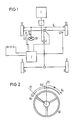
- FIG. 1 shows a schematic representation of a vehicle with all-wheel drive, in which a motor 1 drives the front wheels 51 and 52 via a manual transmission 2, a transfer case 3 and a controllable limited slip differential 4.
- the front wheels are moved via the steering 6 and the steering wheel 61.
- a speed sensor 53 is assigned to each of the front wheels and detects the wheel speed.
- a steering angle sensor 62 is located on the steering wheel 61 and detects the direction and amount of the movements of the steering wheel.
- the signals supplied by the speed sensors 53 and the rotation angle sensor 62 are processed in a control unit 7.
- the rear wheels 8 are also driven from the transfer case 3.
- the method according to the invention can also be used in vehicles with pure front-wheel drive.
- the method described here provides that the control unit 7 determines when one of the drive wheels 51, 52 is spinning; it evaluates the signals supplied by the speed sensors 53.
- the ratio of the signals supplied by the two sensors 53 serves as a criterion as to whether one of the drive wheels 51, 52 is spinning. A certain difference is allowed to allow normal cornering. If this difference exceeds a certain amount, the differential lock 4 is actuated.
- the invention makes use of the knowledge that the steering 6 of the vehicle is moved in the direction of the vehicle side by the occurrence of different peripheral forces, on which the lower peripheral forces act on the drive wheel 51, 52. If, due to the road condition, the drive wheel 51 has poor grip and spins, but the other drive wheel 52 has good grip, and then the differential lock 4 is switched on, it can be expected that a disturbing torque occurs in the direction of the drive wheel 51 at the steering 6.
- the control unit 7 uses the values supplied by the rotation angle sensor 62 to determine whether the steering wheel 61 is moving in the direction of the side of the vehicle on which the spinning drive wheel 51 is located. In the following, this direction is called the Rn direction (low friction coefficient direction). The other direction is called the Rh direction in the following (coefficient of friction-high direction). If the steering wheel 61 moves in the Rn direction, it is assumed that different coefficients of friction between the road surface and the drive wheels 51, 52 act on the steering 6. Thereupon, the degree of locking of the differential lock 4 is reduced until the steering wheel is moved again in the Rh direction, from which it is concluded that either the moment on the steering wheel no longer acts or the driver actively countersteers.
- FIG. 1 A development of the method is illustrated by FIG. At the beginning of the automatic actuation of the differential lock 4, the starting position PO of the steering wheel 61 is stored.
- Steering angles that occur in the Rh direction are evaluated as counter-steering by the driver on the disturbance torque. This does not affect the regulation of the degree of locking.
- the steering wheel 61 is in a new position P1. Steering angles that occur from this new position in the Rn1 direction are regarded as corrections by the driver when counter-steering as long as the steering wheel 61 has not yet reached its starting position PO. Only when the steering wheel Moving beyond the position PO in the Rn direction, the degree of locking is reduced.
- the control unit acts on the brake of the spinning wheel.
- the control unit uses a rotation angle sensor attached to the steering wheel to determine whether the steering wheel is moving in the direction of the side of the vehicle on which the spinning drive wheel is located (Rn direction). If the steering wheel moves in the Rn direction, the braking intervention is reduced. At the beginning of the brake intervention, the starting position PO of the steering wheel is saved. Analogous to the use of a regulated differential lock, steering locks that are attributable to the driver's counter-steering are recognized and do not influence the use of the vehicle brake.
Abstract
Description
Die Erfindung bezieht sich auf ein Verfahren gemäß Oberbegriff von Anspruch 1.The invention relates to a method according to the preamble of
Bei bekannten Fahrzeugen mit angetriebener Vorderachse bewirken unterschiedliche Umfangskräfte am rechten und linken Vorderrad über die Lenkgeometrie ein Moment am Lenkrad. Dieses Moment bewirkt ein Abweichen des Fahrzeugs von der gewünschten Fahrtrichtung. In "Matschinsky, Die Radführungen der Straßenfahrzeuge, Verlag TÜV Rheinland, S. 176-178" sind die Zusammenhänge zwischen den auf die Räder wirkenden Kräfte und dem sich daraus ergebenden Moment am Lenkrad beschrieben.In known vehicles with a driven front axle, different circumferential forces on the right and left front wheels cause a moment on the steering wheel via the steering geometry. This moment causes the vehicle to deviate from the desired direction of travel. "Matschinsky, Die Radführung der Straßenfahrzeuge, Verlag TÜV Rheinland, pp. 176-178" describes the relationships between the forces acting on the wheels and the resulting moment on the steering wheel.
Bei Fahrzeugen mit Achsdifferential ohne Sperre treten nur geringe Umfangskraftdifferenzen auf und damit auch nur geringe Momente am Lenkrad. Bei sehr unterschiedlicher Haftung der Antriebsräder kann dann der Fall eintreten, daß das Antriebsrad, mit der schlechten Haftung durchdreht und das andere Antriebsrad stillsteht. Das Fahrzeug entwickelt dann trotz guter Haftung eines Antriebsrades keinen oder nur ungenügenden Vortrieb.In vehicles with axle differential without lock, there are only slight differences in the circumferential force and therefore only small moments on the steering wheel. In the case of very different adhesion of the drive wheels, it can then occur that the drive wheel spins with the poor adhesion and the other drive wheel stands still. The vehicle then develops no or insufficient propulsion despite the good grip of a drive wheel.
Um diesen nachteiligen Effekt des Differentiales und das Durchdrehen zu beseitigen gibt es zwei Möglichkeiten: Entweder eine Differentialsperre zu verwenden, welche die Antriebskräfte in einem festen Verhältnis auf die Antriebsräder verteilt; oder am durchdrehenden Rad die Fahrzeugbremse zu betätigen. Dies hat jedoch in der zuvor geschilderten Situation ein Moment am Lenkrad zur Folge, das auf die unterschiedlichen Reibungsbeiwerte zwischen Fahrbahn und Antriebsrädern zurückzuführen ist.There are two ways of eliminating this adverse effect of the differential and spinning: either using a differential lock that distributes the drive forces to the drive wheels in a fixed ratio; or to actuate the vehicle brake on the spinning wheel. However, in the situation described above, this results in a moment on the steering wheel which is due to the different coefficients of friction between the road surface and the drive wheels.
Wird nun bei bekannten Vorderradantrieben, wenn eine bestimmte Drehzahldifferenz zwischen den beiden Antriebsrädern auftritt, automatisch die Differentialsperre zugeschaltet, oder die Fahrzeugbremse betätigt, kann das dadurch entstehende Moment am Lenkrad für den Fahrer überraschend auftreten und ein Abweichen von der gewünschten Fahrtrichtung bewirken.With known front wheel drives, if a certain speed difference occurs between the two drive wheels, If the differential lock is switched on automatically or the vehicle brake is actuated, the resulting moment on the steering wheel can occur unexpectedly for the driver and cause a deviation from the desired direction of travel.
Aufgabe der Erfindung ist es, ein Verfahren anzugeben, bei welchem bei automatisch zugeschalteter Differentialsperre oder automatisch betätigter Bremse keine Rückwirkung des Reibungsbeiwertes auf die Lenkung auftritt.The object of the invention is to provide a method in which, with an automatically activated differential lock or an automatically operated brake, there is no reaction of the coefficient of friction on the steering.
Die erfindungsgemäße Lösung dieser Aufgabe ist in Anspruch 1 gekennzeichnet.The inventive solution to this problem is characterized in
Die Erfindung wird anhand zweier Figuren und der Bezugszeichen -und Begriffsliste näher erläutert.The invention is explained in more detail with reference to two figures and the list of reference symbols and terms.
Die Figur 1 zeigt in schematischer Darstellung ein Fahrzeug mit Allradantrieb, bei dem ein Motor 1, über ein Schaltgetriebe 2, ein Verteilergetriebe 3 und ein regelbares Sperrdifferential 4 die Vorderräder 51 und 52 antreibt. Die Vorderräder werden über die Lenkung 6 und das Lenkrad 61 bewegt. Jedem der Vorderräder ist ein Drehzahlsensor 53 zugeordnet, der die Raddrehzahl erfaßt. Am Lenkrad 61 sitzt ein Drehwinkelsensor 62, der Richtung und Betrag der Bewegungen des Lenkrades erfasst. Die von den Drehzahlsensoren 53 und dem Drehwinkelsensor 62 gelieferten Signale werden in einem Steuergerät 7 verarbeitet. Vom Verteilergetriebe 3 aus werden auch die Hinterräder 8 angetrieben. Das erfindungsgemäße Verfahren ist aber ebenso bei Fahrzeugen mit reinem Vorderradantrieb anwendbar.1 shows a schematic representation of a vehicle with all-wheel drive, in which a
Das hier beschriebene Verfahren sieht vor, daß das Steuergerät 7 feststellt, wenn eines der Antriebsräder 51, 52 durchdreht; es wertet dazu die von den Drehzahlsensoren 53 gelieferten Signale aus. Als Kriterium ob eines der Antriebsräder 51, 52 durchdreht, dient das Verhältnis der von den beiden Sensoren 53 gelieferten Signale. Eine gewisse Differenz ist erlaubt, um normale Kurvenfahrt zuzulassen. Übersteigt diese Differenz ein bestimmtes Maß wird die Differentialsperre 4 betätigt. Die Erfindung macht sich dabei die Erkenntnis zunutze, daß durch das Auftreten unterschiedlicher Umfangskräfte die Lenkung 6 des Fahrzeugs in Richtung der Fahrzeugseite bewegt wird, auf der die niedrigeren Umfangskräfte auf das Antriebsrad 51, 52 wirken. Wenn aufgrund des Fahrbahnzustandes das Antriebsrad 51 schlechte Haftung hat und durchdreht, das andere Antriebsrad 52 aber gute Haftung besitzt, und daraufhin die Differentialsperre 4 eingeschaltet wird, ist zu erwarten, daß an der Lenkung 6 ein störendes Moment in Richtung des Antriebsrades 51 auftritt.The method described here provides that the
Das Steuergerät 7 stellt anhand der vom Drehwinkelsensor 62 gelieferten Werte fest, ob sich das Lenkrad 61 in Richtung der Fahrzeugseite bewegt, auf der sich das durchdrehende Antriebsrad 51 befindet. Im folgenden wird diese Richtung die Rn-Richtung (Reibungsbeiwert-niedrig-Richtung) genannt. Die andere Richtung wird im folgenden Rh-Richtung (Reibungsbeiwert-hoch-Richtung) genannt. Wenn sich das Lenkrad 61 in Rn-Richtung bewegt, wird angenommen, daß unterschiedliche Reibungsbeiwerte zwischen Fahrbahn und Antriebsräder 51, 52 auf die Lenkung 6 zurückwirken. Daraufhin wird der Sperrgrad der Differentialsperre 4 soweit verringert bis das Lenkrad wieder in Rh-Richtung bewegt wird, woraus geschlossen wird, daß entweder das Moment am Lenkrad nicht mehr wirkt oder aber der Fahrer aktiv gegenlenkt.The
Durch die Figur 2 ist eine Weiterbildung des Verfahrens veranschaulicht. Zu Beginn der automatischen Betätigung der Differentialsperre 4 wird die Ausgangsposition PO des Lenkrades 61 gespeichert.A development of the method is illustrated by FIG. At the beginning of the automatic actuation of the differential lock 4, the starting position PO of the
Lenkeinschläge, die in Rh-Richtung erfolgen, werden als Gegenlenken des Fahrers auf das Störmoment gewertet. Die Regelung des Sperrgrades wird dadurch nicht beeinflußt. Durch dieses Gegenlenken befindet sich das Lenkrad 61 in einer neuen Position P1. Lenkeinschläge, die von dieser neuen Position in Rn1-Richtung erfolgen, werden als Korrekturen des Fahrers beim Gegenlenken betrachtet, solange das Lenkrad 61 seine Ausgangsposition PO noch nicht erreicht hat. Erst wenn sich das Lenkrad über die Position PO hinaus in Rn-Richtung bewegt, wird der Sperrgrad verringert.Steering angles that occur in the Rh direction are evaluated as counter-steering by the driver on the disturbance torque. This does not affect the regulation of the degree of locking. As a result of this countersteering, the
Gemäß einer zweiten Ausführungsform der Erfindung wirkt das Steuergerät auf die Bremse des durchdrehenden Rades. Auch in diesem Fall stellt das Steuergerät anhand eines am Lenkrad befestigten Drehwinkelsensors fest, ob sich das Lenkrad in Richtung der Fahrzeugseite bewegt, auf der sich das durchdrehende Antriebsrad befindet (Rn-Richtung). Wenn sich das Lenkrad in Rn-Richtung bewegt, wird der Bremseingriff verringert. Zu Beginn des Bremseneingriffes wird die Ausgangsposition PO des Lenkrades gespeichert. Analog wie bei dem Einsatz einer geregelten Differentialsperre werden Lenkeinschläge, die auf das Gegenlenken des Fahrers zurückzuführen sind, erkannt und beeinflussen nicht den Einsatz der Fahrzeugbremse.According to a second embodiment of the invention, the control unit acts on the brake of the spinning wheel. In this case too, the control unit uses a rotation angle sensor attached to the steering wheel to determine whether the steering wheel is moving in the direction of the side of the vehicle on which the spinning drive wheel is located (Rn direction). If the steering wheel moves in the Rn direction, the braking intervention is reduced. At the beginning of the brake intervention, the starting position PO of the steering wheel is saved. Analogous to the use of a regulated differential lock, steering locks that are attributable to the driver's counter-steering are recognized and do not influence the use of the vehicle brake.
Claims (9)
dadurch gekennzeichnet, daß
characterized in that
dadurch gekennzeichnet, daß
characterized in that
dadurch gekennzeichnet, daß
characterized in that
dadurch gekennzeichnet, daß
characterized in that
dadurch gekennzeichnet, daß
characterized in that
dadurch gekennzeichnet, daß
characterized in that
dadurch gekennzeichnet, daß
characterized in that
dadurch gekennzeichnet, daß
characterized in that
dadurch gekennzeichnet, daß
characterized in that
Priority Applications (2)
| Application Number | Priority Date | Filing Date | Title |
|---|---|---|---|
| DE90109816T DE59002758D1 (en) | 1990-05-23 | 1990-05-23 | Method for regulating the degree of locking of a locking differential in vehicles with a driven front axle. |
| EP19900109816 EP0457945B1 (en) | 1990-05-23 | 1990-05-23 | Method of control of the engagement of a limited slip differential for front wheel driven vehicles |
Applications Claiming Priority (1)
| Application Number | Priority Date | Filing Date | Title |
|---|---|---|---|
| EP19900109816 EP0457945B1 (en) | 1990-05-23 | 1990-05-23 | Method of control of the engagement of a limited slip differential for front wheel driven vehicles |
Publications (2)
| Publication Number | Publication Date |
|---|---|
| EP0457945A1 true EP0457945A1 (en) | 1991-11-27 |
| EP0457945B1 EP0457945B1 (en) | 1993-09-15 |
Family
ID=8204017
Family Applications (1)
| Application Number | Title | Priority Date | Filing Date |
|---|---|---|---|
| EP19900109816 Expired - Lifetime EP0457945B1 (en) | 1990-05-23 | 1990-05-23 | Method of control of the engagement of a limited slip differential for front wheel driven vehicles |
Country Status (2)
| Country | Link |
|---|---|
| EP (1) | EP0457945B1 (en) |
| DE (1) | DE59002758D1 (en) |
Cited By (1)
| Publication number | Priority date | Publication date | Assignee | Title |
|---|---|---|---|---|
| US6386308B1 (en) * | 1997-02-06 | 2002-05-14 | Toyota Jidosha Kabushiki Kaisha | Apparatus for controlling drive forces of vehicle drive wheels connected by differential, by braking drive wheel having smaller critical drive force |
Citations (4)
| Publication number | Priority date | Publication date | Assignee | Title |
|---|---|---|---|---|
| FR2434969A1 (en) * | 1978-08-30 | 1980-03-28 | Bardot Michel | Motor vehicle differential with auto-controlled slip - has electronic circuit including potentiometers, to control piston acting on clutch |
| DE3440492A1 (en) * | 1984-11-06 | 1986-05-07 | Xaver Fendt & Co, 8952 Marktoberdorf | Method and device for automatically reducing the relative slip of a pair of axle shafts of a motor vehicle |
| EP0311139A2 (en) * | 1987-10-09 | 1989-04-12 | Nissan Motor Co., Ltd. | Differential limiting force control system responsive to vehicle speed and steering angle |
| FR2638401A1 (en) * | 1988-10-28 | 1990-05-04 | Peugeot | Method and device for driving a controlled differential, particularly for a motor vehicle |
-
1990
- 1990-05-23 DE DE90109816T patent/DE59002758D1/en not_active Expired - Lifetime
- 1990-05-23 EP EP19900109816 patent/EP0457945B1/en not_active Expired - Lifetime
Patent Citations (4)
| Publication number | Priority date | Publication date | Assignee | Title |
|---|---|---|---|---|
| FR2434969A1 (en) * | 1978-08-30 | 1980-03-28 | Bardot Michel | Motor vehicle differential with auto-controlled slip - has electronic circuit including potentiometers, to control piston acting on clutch |
| DE3440492A1 (en) * | 1984-11-06 | 1986-05-07 | Xaver Fendt & Co, 8952 Marktoberdorf | Method and device for automatically reducing the relative slip of a pair of axle shafts of a motor vehicle |
| EP0311139A2 (en) * | 1987-10-09 | 1989-04-12 | Nissan Motor Co., Ltd. | Differential limiting force control system responsive to vehicle speed and steering angle |
| FR2638401A1 (en) * | 1988-10-28 | 1990-05-04 | Peugeot | Method and device for driving a controlled differential, particularly for a motor vehicle |
Non-Patent Citations (1)
| Title |
|---|
| SOVIET INVENTIONS ILLUSTRATED Sektion Mechanik, Woche 8515, 22. Mai 1985, Zusammenfassung Nr. 91938/15, Derwent Publications Ltd., London, GB; & SU - A - 1115928 (BELORUSSIAN POLY) 30.09.1984 * |
Cited By (1)
| Publication number | Priority date | Publication date | Assignee | Title |
|---|---|---|---|---|
| US6386308B1 (en) * | 1997-02-06 | 2002-05-14 | Toyota Jidosha Kabushiki Kaisha | Apparatus for controlling drive forces of vehicle drive wheels connected by differential, by braking drive wheel having smaller critical drive force |
Also Published As
| Publication number | Publication date |
|---|---|
| DE59002758D1 (en) | 1993-10-21 |
| EP0457945B1 (en) | 1993-09-15 |
Similar Documents
| Publication | Publication Date | Title |
|---|---|---|
| DE69935471T2 (en) | Yaw angle control method for motor vehicles | |
| EP1016572B1 (en) | Device and procedure for stabilising a vehicle coupling consisting of a tractor and a trailer | |
| DE3831105C1 (en) | ||
| EP0318857A1 (en) | System for controlling the torque of the internal combustion engine of an automotive vehicle | |
| DE102018107612A1 (en) | Motor vehicle with rear-wheel steering and torque vectoring on the rear wheel axle | |
| DE102008045078A1 (en) | Control system for a vehicle | |
| DE3939069A1 (en) | Motor vehicle with rear-wheel slip correction device - has brake applied to driven wheel on outside of curve while inside wheel accelerates to restore stability | |
| WO1987002948A1 (en) | System for adjusting sleepage of a drive | |
| EP1045783B1 (en) | Device and method for limiting a backward rolling speed of a motor vehicle | |
| EP1799484B1 (en) | Method and device for controlling the locking degree of an electronically controllable differential lock | |
| WO2021083751A1 (en) | Method for controlling a motor vehicle in emergency steering mode by means of front wheel brake-based torque vectoring | |
| DE2818813C2 (en) | ||
| DE102007007442A1 (en) | Steering moment manipulation method for steering system of vehicle, involves producing auxiliary moment during obtaining maximum steering angle or steering wheel angle value resulting from transverse dynamic evaluation | |
| DE102004042188B4 (en) | The vehicle motion control device | |
| EP1661750B1 (en) | Method and device for closed loop control of vehicle speed | |
| DE102017124317A1 (en) | Method for determining a coefficient of friction between a wheel of a motor vehicle and a road surface with torque vectoring | |
| DE19954131B4 (en) | A method for reducing wheel slip of a motor vehicle | |
| DE19723841B4 (en) | Motor vehicle and method for operating a motor vehicle with a device for controlling centrifugal movements | |
| DE19618624C1 (en) | Device for evaluation of signals from sensor | |
| EP0457945A1 (en) | Method of control of the engagement of a limited slip differential for front wheel driven vehicles | |
| DE19909453A1 (en) | Method of improving the driving behavior of a vehicle when driving on a curved path with a change in vehicle dynamic behavior especially engine torque | |
| EP0511473A2 (en) | Drive slip control system | |
| DE10206730B4 (en) | Yaw damping in the vehicle steering | |
| DE102019209719B4 (en) | Method for preventing skidding in a vehicle | |
| DE102016009587A1 (en) | Method for operating a motor vehicle with an actively controllable rear axle steering |
Legal Events
| Date | Code | Title | Description |
|---|---|---|---|
| PUAI | Public reference made under article 153(3) epc to a published international application that has entered the european phase |
Free format text: ORIGINAL CODE: 0009012 |
|
| 17P | Request for examination filed |
Effective date: 19901205 |
|
| AK | Designated contracting states |
Kind code of ref document: A1 Designated state(s): AT BE CH DE DK ES FR GB GR IT LI LU NL SE |
|
| RBV | Designated contracting states (corrected) |
Designated state(s): DE FR GB IT |
|
| 17Q | First examination report despatched |
Effective date: 19930218 |
|
| GRAA | (expected) grant |
Free format text: ORIGINAL CODE: 0009210 |
|
| AK | Designated contracting states |
Kind code of ref document: B1 Designated state(s): DE FR GB IT |
|
| REF | Corresponds to: |
Ref document number: 59002758 Country of ref document: DE Date of ref document: 19931021 |
|
| ITF | It: translation for a ep patent filed |
Owner name: MODIANO & ASSOCIATI S.R |
|
| GBT | Gb: translation of ep patent filed (gb section 77(6)(a)/1977) |
Effective date: 19931122 |
|
| ET | Fr: translation filed | ||
| PLBE | No opposition filed within time limit |
Free format text: ORIGINAL CODE: 0009261 |
|
| STAA | Information on the status of an ep patent application or granted ep patent |
Free format text: STATUS: NO OPPOSITION FILED WITHIN TIME LIMIT |
|
| 26N | No opposition filed | ||
| REG | Reference to a national code |
Ref country code: GB Ref legal event code: IF02 |
|
| PG25 | Lapsed in a contracting state [announced via postgrant information from national office to epo] |
Ref country code: IT Free format text: LAPSE BECAUSE OF NON-PAYMENT OF DUE FEES;WARNING: LAPSES OF ITALIAN PATENTS WITH EFFECTIVE DATE BEFORE 2007 MAY HAVE OCCURRED AT ANY TIME BEFORE 2007. THE CORRECT EFFECTIVE DATE MAY BE DIFFERENT FROM THE ONE RECORDED. Effective date: 20050523 |
|
| PGFP | Annual fee paid to national office [announced via postgrant information from national office to epo] |
Ref country code: GB Payment date: 20080522 Year of fee payment: 19 |
|
| PGFP | Annual fee paid to national office [announced via postgrant information from national office to epo] |
Ref country code: DE Payment date: 20090531 Year of fee payment: 20 |
|
| GBPC | Gb: european patent ceased through non-payment of renewal fee |
Effective date: 20090523 |
|
| REG | Reference to a national code |
Ref country code: FR Ref legal event code: ST Effective date: 20100129 |
|
| PG25 | Lapsed in a contracting state [announced via postgrant information from national office to epo] |
Ref country code: FR Free format text: LAPSE BECAUSE OF NON-PAYMENT OF DUE FEES Effective date: 20090602 |
|
| PGFP | Annual fee paid to national office [announced via postgrant information from national office to epo] |
Ref country code: FR Payment date: 20080526 Year of fee payment: 19 |
|
| PG25 | Lapsed in a contracting state [announced via postgrant information from national office to epo] |
Ref country code: GB Free format text: LAPSE BECAUSE OF NON-PAYMENT OF DUE FEES Effective date: 20090523 |
|
| PG25 | Lapsed in a contracting state [announced via postgrant information from national office to epo] |
Ref country code: DE Free format text: LAPSE BECAUSE OF EXPIRATION OF PROTECTION Effective date: 20100523 |