EP0457770B1 - Device for controlling and regulating the illumination and feed speed of a motion picture film in a motion picture camera - Google Patents
Device for controlling and regulating the illumination and feed speed of a motion picture film in a motion picture camera Download PDFInfo
- Publication number
- EP0457770B1 EP0457770B1 EP90901754A EP90901754A EP0457770B1 EP 0457770 B1 EP0457770 B1 EP 0457770B1 EP 90901754 A EP90901754 A EP 90901754A EP 90901754 A EP90901754 A EP 90901754A EP 0457770 B1 EP0457770 B1 EP 0457770B1
- Authority
- EP
- European Patent Office
- Prior art keywords
- transport speed
- regulator
- aperture angle
- motion picture
- shutter aperture
- Prior art date
- Legal status (The legal status is an assumption and is not a legal conclusion. Google has not performed a legal analysis and makes no representation as to the accuracy of the status listed.)
- Expired - Lifetime
Links
Images


Classifications
-
- G—PHYSICS
- G03—PHOTOGRAPHY; CINEMATOGRAPHY; ANALOGOUS TECHNIQUES USING WAVES OTHER THAN OPTICAL WAVES; ELECTROGRAPHY; HOLOGRAPHY
- G03B—APPARATUS OR ARRANGEMENTS FOR TAKING PHOTOGRAPHS OR FOR PROJECTING OR VIEWING THEM; APPARATUS OR ARRANGEMENTS EMPLOYING ANALOGOUS TECHNIQUES USING WAVES OTHER THAN OPTICAL WAVES; ACCESSORIES THEREFOR
- G03B9/00—Exposure-making shutters; Diaphragms
- G03B9/08—Shutters
- G03B9/10—Blade or disc rotating or pivoting about axis normal to its plane
- G03B9/12—Two relatively-adjustable aperture-defining members moving as a unit
-
- G—PHYSICS
- G03—PHOTOGRAPHY; CINEMATOGRAPHY; ANALOGOUS TECHNIQUES USING WAVES OTHER THAN OPTICAL WAVES; ELECTROGRAPHY; HOLOGRAPHY
- G03B—APPARATUS OR ARRANGEMENTS FOR TAKING PHOTOGRAPHS OR FOR PROJECTING OR VIEWING THEM; APPARATUS OR ARRANGEMENTS EMPLOYING ANALOGOUS TECHNIQUES USING WAVES OTHER THAN OPTICAL WAVES; ACCESSORIES THEREFOR
- G03B19/00—Cameras
- G03B19/18—Motion-picture cameras
-
- G—PHYSICS
- G03—PHOTOGRAPHY; CINEMATOGRAPHY; ANALOGOUS TECHNIQUES USING WAVES OTHER THAN OPTICAL WAVES; ELECTROGRAPHY; HOLOGRAPHY
- G03B—APPARATUS OR ARRANGEMENTS FOR TAKING PHOTOGRAPHS OR FOR PROJECTING OR VIEWING THEM; APPARATUS OR ARRANGEMENTS EMPLOYING ANALOGOUS TECHNIQUES USING WAVES OTHER THAN OPTICAL WAVES; ACCESSORIES THEREFOR
- G03B7/00—Control of exposure by setting shutters, diaphragms or filters, separately or conjointly
- G03B7/08—Control effected solely on the basis of the response, to the intensity of the light received by the camera, of a built-in light-sensitive device
- G03B7/081—Analogue circuits
- G03B7/085—Analogue circuits for control of aperture
-
- G—PHYSICS
- G03—PHOTOGRAPHY; CINEMATOGRAPHY; ANALOGOUS TECHNIQUES USING WAVES OTHER THAN OPTICAL WAVES; ELECTROGRAPHY; HOLOGRAPHY
- G03B—APPARATUS OR ARRANGEMENTS FOR TAKING PHOTOGRAPHS OR FOR PROJECTING OR VIEWING THEM; APPARATUS OR ARRANGEMENTS EMPLOYING ANALOGOUS TECHNIQUES USING WAVES OTHER THAN OPTICAL WAVES; ACCESSORIES THEREFOR
- G03B7/00—Control of exposure by setting shutters, diaphragms or filters, separately or conjointly
- G03B7/08—Control effected solely on the basis of the response, to the intensity of the light received by the camera, of a built-in light-sensitive device
- G03B7/091—Digital circuits
- G03B7/095—Digital circuits for control of aperture
Definitions
- the invention relates to a control and regulating device for the transport speed of a film and for the aperture angle of a rotating aperture according to the preamble of claim 1.
- a motion picture camera is known in which the frame rate or transport speed of the motion picture film can be freely selected or preprogrammed and the aperture setting of the motion picture camera is tracked when the setting of the frame rate is changed to adjust the exposure of the motion picture film.
- the motor controller of the motion picture camera and a circuit connected to the aperture adjustment motor are connected to the output of a control circuit, which in turn is connected to a generator circuit into which the desired frame rate and additionally a transition time from one frame rate to another can be entered.
- the known control circuit gives a signal corresponding to the selected frame rate to the circuit coupled to the aperture adjustment motor for the corresponding change of the camera aperture within the selected transition time from.
- a film recording camera which has a gripper mechanism, a rotating diaphragm and a spiked roller which are each connected to a separate drive motor, the drive motors being coupled to one another via a control arrangement.
- the frame rate of the camera is freely selectable, while the aperture setting on the film camera is dependent on the freely selected frame rate.
- the drive motors are coupled to actual value detection devices in the form of photoelectric sensors, which emit a corresponding actual value signal to comparators which are additionally acted upon by the respectively set target values.
- a control system for a motion picture camera which contains a programmable microcomputer, which the various camera modules according to the desired sequence functions such as normal running with sound or silent cassette, single scrolling, timer function, fade or fade and Activation fade.
- the object of the present invention is to provide a control and regulating device for a motion picture camera, which ensures a predetermined exposure time at different film transport speeds or varying lighting conditions in film recording operation, enables predeterminable transition times from one film transport speed to another and ensures maximum ease of use for carrying out defined picture recording sequences.
- the solution according to the invention ensures that in film recording operation the exposure time of the motion picture film is kept constant within predetermined limits at variable running speeds or different exposure conditions, so that, for example, when increasing the film transport speed for slow motion effects or when the motion picture camera is pivoted with different exposure of the recording object Sufficient exposure of the motion picture film is guaranteed and the possibility of additional effects is created.
- the solution according to the invention alternatively enables variable or constant exposure of the motion picture film by means of common or separate default values for the film transport speed and the aperture opening angle over the entire speed range of the motion picture camera.
- control and regulating device ensures a high degree of user-friendliness, since both the transport speed and the aperture opening angle can be pre-programmed and stored, so that specific, predetermined image recording sequences can be entered before the recording and sequentially in the film recording mode as a sequence of program steps of different film transport speed and Aperture angle can be obtained.
- the cameraman thus has the free choice of a desired exposure function without having to concentrate on the setting of the desired exposure function and is thus distracted from the observation of the subject by the camera viewfinder.
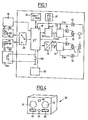
- FIG. 1 shows the essential components for realizing a control and Control device for controlling the exposure and transport speed of a motion picture film in a motion picture camera.
- a film transport motor 26 controlled by an amplifier 24 is provided for transporting the motion picture film, which is connected to a corresponding gripper switching mechanism via a gear.
- the drive shaft of the film transport motor 26 is fixedly connected to an angle encoder disc 27, so that the rotational speed or frequency and, if appropriate, the exact position of the film transport motor 26 can be detected by means of an opto-electronic position sensing device and can be passed on to a speed controller 23 via an amplifier 25.
- the actual value f is the transport speed is fed to both the speed controller 23 and a central processor 16.
- the speed controller 23 is additionally f with a target value of the transport speed is applied.
- This setpoint value is output by a synthesizer 22, the inputs of which are connected both to an oscillator 21, which outputs a reference frequency f ref to the synthesizer 22, and to an output of the central processor 16.
- the reference frequency f to the transport speed is also fed back to an input of the central processor sixteenth
- the speed controller 23 performs both a speed control depending on that emitted by the synthesizer Control value and a phase comparison between the actual value and the target value of the phase angle by.
- a setpoint value of the aperture opening angle V soll is output by the central processor 16 via a digital / analog converter 14 to a position controller 13 which is additionally acted upon by an actual value Vactual of the aperture opening angle.
- the position controller controls a diaphragm adjustment motor 3, which is preferably connected to the circulating diaphragm shaft, rotates with the circulating diaphragm and, with appropriate control by the position controller, causes a relative movement of the diaphragm adjusting wing with respect to the rotating circulating diaphragm.
- the diaphragm adjustment vane is connected to a potentiometer 6, which outputs a signal corresponding to the position of the diaphragm adjustment vane with respect to the rotating diaphragm, both at standstill and during operation, to the position controller 13 via a second amplifier 12.
- an optical sensor 20 can be arranged in the area of the adjustable orifice plate, which detects the respective aperture opening angle in the course of the adjustable orifice plate, i.e. the opening time of the orifice plate is detected and passed on to a further input of the central processor 16, so that system tolerances are eliminated and an additional comparison input in digital form to the central processor 16 is accomplished.
- the central processor 16 is connected to a memory 29, which preferably consists of a read-only memory and a There is random access memory.
- An additional input of the central processor 16 is via a multiplexer 28 with an external remote control unit 30; 181, 182, 183, via which set values for the transport speed and the aperture opening angle can be set, which are triggered by means of a program button 33 on the remote control unit or a program button 185 on the motion picture camera.
- the central processor 16 can be connected to a programming device 19 via a serial or parallel interface, with which setpoints of the transport speed and the aperture opening angle can be preprogrammed.
- the preprogrammed data preferably contain start and end values of the transport speed and the aperture opening angle as well as the time within which the change is to take place.
- the data entered by means of the programming device 19 are stored in the memory 29 and triggered with the program button 185 on the motion picture camera or the program button 33 on the remote control unit as a sequence of program steps of different transport speeds and different aperture angles.
- both the aperture angle and the transport speed can be changed.
- the at the power sources of the remote control unit 30; Values set to 181, 182, 183 are sent to the central processor via an analog / digital converter 16 emitted, which forwards the digital value of the aperture angle to the digital / analog converter 14 for regulating the aperture angle.
- the central processor 16 likewise receives a value of the transport speed via analog / digital converters, with which it sets the downstream synthesizer 22 in a stable manner with a fixed digital value.
- the synthesizer 22 is a controller which is supplied with a quartz-stable reference frequency output by the oscillator 21 and which thus regulates the transport speed. As a result of a manual adjustment of the transport speed, the current intensity emitted by the current source of the external remote control unit is converted into digital values, so that quartz-stable regulation via the synthesizer 22 is possible.
- a voltage / frequency converter can of course also be used.
- the respective aperture opening angle can be calculated in the central processor 16 by the values of each speed detected by the optical sensor, so that the aperture opening angle can also be checked and, if necessary, corrected during the run-up phase.
- FIG. 2 shows an example of a program sequence with different transport speeds and different diaphragm opening angles as a function of a predefined setpoint change.
- the program step shown in Figure 2 shows the time t0 to an initial set value of the shutter aperture angle of V to eg. 90 ° and an initial target value of the transport speed of f to example. 25 frames per second.
- a change in the transport speed and the shutter aperture is triggered t0 at the time that in an end setpoint should of eg. 180 ° for the set value of the shutter aperture V and f a target value of the transport speed is of, for example, 50 frames per second, opens, at the time t1 is reached.
- the predetermined time period ⁇ t for changing the transport speed and the aperture opening angle is, for example, 20 seconds.
- further program steps can be triggered, for example a further increase in the transport speed with an increased increase in the transport speed with an enlarged aperture opening angle or a reduction in the transport speed and aperture aperture angle also below the initial setpoint value shown in FIG. 2 of, for example, 90 ° Aperture angle and 25 frames per second transport speed.
- a setting of default values for any can be made regardless of the transport speed Aperture opening angles take place, for example when special effects are to be achieved or when the recording objects are filmed with different light sources.
- Figure 3 shows a schematic perspective view of the adjustable orifice plate, which consists of a one-piece orifice mirror plate 2, which is fixedly connected to the orifice plate shaft 1, and an adjustable orifice plate 4, which is connected via an adjustment axis 30 to an adjusting motor connected to the orifice plate shaft 1 3 is coupled.
- the circulating diaphragm shaft 1 has five slip ring contacts 10, which are used to transmit the voltage supply to the adjusting motor 3 and to transmit a measured value representing the position of the diaphragm adjusting vane 4 in relation to the circulating diaphragm 2.
- the adjustment motor 3 To adjust the aperture or the aperture adjustment sector of the motion picture camera, the adjustment motor 3 must bring about a relative movement between the peripheral aperture 2 and the aperture adjustment wing 4. This is achieved in that the adjusting motor 3 is supplied with a corresponding voltage driving it via the slip ring contacts 10, the polarity of which specifies the direction of the adjustment of the diaphragm adjustment wing to a larger or smaller diaphragm opening.
- Two of the five slip ring contacts are connected to the adjusting motor 3 and to the output of a first amplifier 11, the input of which is connected to the central processor 16 via a PID controller 13 and a digital / analog converter 14.
- the three remaining slip ring contacts 10 are connected on the one hand to a detection device for detecting the aperture opening angle, and on the other hand to the input aperture angle and on the other hand to the input of a second amplifier 12, the output of which is connected both to an analog / digital converter 15 and to the PID controller 13 connected is.
- An analog control device 18 is connected to the analog / digital converter 15.
- the output of the analog / digital converter 15 is connected to an input of the central processor 16, which is connected via further inputs to the programming device 19 and to a light barrier 20 which is arranged in the region of the adjustable orifice plate 2, 4.
- Another output of the central processor 16 is connected to a display device 17.
- a corresponding value is set on the analog control device 18 or specified via the programming device 19, which, for example, specifies a change in the aperture depending on the transport speed of the motion picture camera in the form of a ramp-shaped adjustment curve.
- the predetermined setpoint is output via the digital / analog converter 14 and the PID controller 13 and the first amplifier 11 to the slip ring contacts 10 connected to the adjusting motor 3, so that a corresponding change in the voltage supply to the adjusting motor 3 compares a relative movement of the diaphragm adjustment wing 4 the Circulating aperture 2 causes.
- the adjusting motor 3 executes a relative movement to the rotating circulating diaphragm shaft 1 and thereby moves the diaphragm adjusting wing 4 in the direction of a larger or smaller sector and thus in the direction of a larger or smaller diaphragm opening.
- a detection device coupled to the orifice plate 2 and the orifice plate 4 gives a signal corresponding to the respective position of the orifice plate 4 in relation to the orifice plate 2 via three of the five slip ring contacts 10 to the second amplifier 12 and to the analog / digital converter 15 at an input of the central processor 16, which on the one hand displays the respective angular position of the diaphragm adjustment wing 4 on the display device 17 or, in conjunction with the default value given by the analog operating device 18 or the programming device 19, feeds the target / actual value comparison.
- the additional arrangement of a light barrier in the area of the orifice plate 2 causes a measurement of the opening time of the orifice plate 2 during its run by the central processor 16 and an additional target / actual value comparison, so that a fine correction is made, which leads to the accuracy of the aperture adjustment is ensured regardless of any system tolerances.
- the aperture of the motion picture camera can be adjusted manually, automatically in conjunction with, for example Exposure meter or programmed according to a predetermined sequence program. In this way it is possible to adapt the aperture to the respective lighting conditions, to achieve certain desired effects or to adapt the aperture and thus the exposure time of the motion picture film to the respective film speed.
- FIG. 4 shows a remote control unit for connection to a motion picture camera for setting default values for the transport speed and the aperture opening angle, and for triggering predetermined and stored program steps.
- the remote control unit 30 shown schematically in perspective in FIG. 4 is connected to a motion picture camera via a connecting cable (not shown in more detail) or via an infrared ultrasound or radio transmitter and receiver.
- the remote control unit 30 can also be part of a motion picture camera or can be used as a module in a motion picture camera or can be connected to a motion picture camera.
- the remote control unit 30 is used to set default values for the transport speed and the aperture opening angle, and optionally to trigger predetermined and stored program steps.
- the remote control unit 30 contains two control buttons 31, 32, which have rotary potentiometers for setting a preset value for the transport speed and the aperture opening angle are connected, which control the current sources 38, 39 shown in Figure 1, so that different default values of the transport speed and the aperture angle are given as current values.
- a program key 33, 185 which can also be arranged on the programming device 19, is used to activate a stored program when the motion picture camera is not in the recording mode or to delete a stored program when it is pressed twice.
- the program key 33 is used to activate a predetermined program step, so that, for example, a switchover is made from the initial target values for the transport speed and the aperture opening angle to a subsequent final value within a predetermined change of the default values.
- the next program step is triggered by pressing the program button 33 again.
- An activation button 34 is used to bring the motion picture camera from a standstill into the film recording mode, so that either the preset values of the transport speed or the aperture angle set on the control buttons 31, 32 are set or a program step is triggered.
- An intermediate wheel arranged between the two control buttons 31, 32 for setting the transport speed and the aperture angle serves for the mechanical coupling of the two control buttons 31, 32, so that when the intermediate wheel is actuated, both control buttons are adjusted uniformly synchronously. In this way, a forced coupling is brought about, in which the default values for the transport speed and the aperture opening angle are changed at the same time. This ensures a constant exposure over the entire speed range of the motion picture camera and at the same time enables simplified operation, in which only one control element, namely either the idler gear or one of the two control buttons 31, 32, is to be operated in order to change the transport speed or the aperture opening angle bring about.
- the intermediate wheel is axially displaceable so that in a lower position only a common adjustment of the control buttons 31, 32 for setting the default values for the transport speed and the aperture opening angle is possible via suitable rotary potentiometers connected to the control buttons 31, 32, while in an upper one Position in which the idler gear axially from the surface of the remote control unit 30 is removed, the control buttons 31, 32 are released, so that a separate adjustment of the default values for the transport speed and the aperture angle is possible.
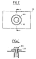
- FIG. 5 shows a plan view of a coaxial arrangement of two control buttons 31, 32 connected with rotary potentiometers
- FIG. 6 a section along the line AA according to FIG. 5 shows the embodiment with the coaxial control buttons 31, 32 in which the connection of both control buttons and thus the coupling of both potentiometers connected to the control buttons 31, 32 is carried out by lifting the upper control button 31, so that the lower control button 32 is coupled to the upper control button 31 by a force-locking connection and, when the upper control button 31 is rotated, the lower control button 32 is forced to Performs rotary motion.
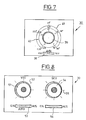
- Figure 7 shows a plan view of a remote control unit 30 with an electrical or electronic coupling of the actuators for setting the default values of the transport speed and the aperture angle.
- control button 39 is provided, with which the setpoint for the transport speed and the aperture opening angle can be adjusted either separately or synchronously.
- An additional switch 38 arranged on the user interface of the remote control unit 30 is designed as a three-pole switch and, depending on the switch position, enables the adjustment of the default values for the transport speed VSU, the change of the default value of the aperture angle SCU and the common adjustment of both default values AUTO for setting a constant exposure time.
- two scales 40, 41 are arranged around the operating button 39, which have values for the transport speed and the aperture opening angle.
- one or the other scale 40, 41 for displaying and setting the desired transport speed or the desired aperture opening angle applies when the switch 38 is in a corresponding position.
- the values for the transport speed and the aperture opening angle can be adjusted in such a way that the operating button 39 engages at predetermined values, so that special setting values are specified at these points. In the case of a continuous adjustment, the values in between can be adjusted without latching elements, so that any value setting between the minimum and maximum transport speed and the minimum and maximum aperture opening angle is possible.
- FIG. 8 shows a top view of an alternative embodiment of the electrical or electronic coupling of the potentiometers.
- two separate potentiometers with adjusting buttons 51, 54 for the transport speed VSU and the aperture opening angle SCU as well as two switches 53, 56 assigned to the two potentiometers are provided, of which one switch 53, assigned to the potentiometer for the transport speed VSU, as a three-pole Switch is executed, while the other switch 56 assigned to the potentiometer for the aperture angle SCU is a two-pole on and off switch.
Abstract
Description
Die Erfindung betrifft eine Steuer- und Regeleinrichtung für die Transportgeschwindigkeit eines Films sowie für den Blendenöffnungswinkel einer Umlaufblende gemäß dem Oberbegriff des Anspruchs 1.The invention relates to a control and regulating device for the transport speed of a film and for the aperture angle of a rotating aperture according to the preamble of
Aus der DE-C-28 48 676 ist eine Laufbildkamera bekannt, bei der die Bildfolgefrequenz bzw. Transportgeschwindigkeit des Laufbildfilms frei wählbar oder vorprogrammierbar ist sind und die Blendeneinstellung der Laufbildkamera bei einer Änderung der Einstellung der Bildfolgefrequenz zur Anpassung der Belichtung des Laufbildfilms nachgeführt wird. Zu diesem Zweck sind die Motorsteuerung der Laufbildkamera und eine mit dem Blendenverstellmotor verbundene Schaltung mit dem Ausgang einer Steuerschaltung verbunden, die wiederum mit einer Generatorschaltung verbunden ist, in die die gewünschte Bildfolgefrequenz und zusätzlich eine Übergangszeit von einer Bildfolgefrequenz zur anderen eingebbar ist.From DE-C-28 48 676 a motion picture camera is known in which the frame rate or transport speed of the motion picture film can be freely selected or preprogrammed and the aperture setting of the motion picture camera is tracked when the setting of the frame rate is changed to adjust the exposure of the motion picture film. For this purpose, the motor controller of the motion picture camera and a circuit connected to the aperture adjustment motor are connected to the output of a control circuit, which in turn is connected to a generator circuit into which the desired frame rate and additionally a transition time from one frame rate to another can be entered.
Die bekannte Steuerschaltung gibt innerhalb der gewählten Übergangszeit ein der gewählten Bildfolgefrequenz entsprechendes Signal an die mit dem Blendenverstellmotor gekoppelte Schaltung zur entsprechenden Änderung der Kamerablende ab. Somit ist bei dieser Steuerschaltung sowohl die Transportgeschwindigkeit programmierbar als auch die übergangszeit zwischen vorwählbaren Bildfolgefrequenzen unter Berücksichtigung der Blendenanpassung wählbar.The known control circuit gives a signal corresponding to the selected frame rate to the circuit coupled to the aperture adjustment motor for the corresponding change of the camera aperture within the selected transition time from. With this control circuit, both the transport speed can be programmed and the transition time between preselectable frame rates can be selected, taking the aperture adjustment into account.
Neben einer konstanten Filmbelichtung und einer frei wählbaren Übergangszeit von einer Bildfolgefrequenz oder Filmtransportgeschwindigkeit zur anderen ist es in vielen Anwendungsfällen jedoch üblich, aufeinanderfolgende Filmsequenzen vor der Aufnahme festzulegen und demzufolge erwünscht, diese festgelegten Aufnahmesequenzen nacheinander abrufen zu können, ohne die einzelnen Änderungen an der Laufbildkamera einstellen zu müssen.In addition to a constant film exposure and a freely selectable transition time from one frame rate or film transport speed to another, it is common in many applications to define successive film sequences before recording and, consequently, to be able to call up these defined recording sequences one after the other without having to make the individual changes to the motion picture camera to have to.
Aus der DE-A-28 50 065 ist eine Filmaufnahmekamera bekannt, die ein Greiferwerk, eine rotierende Blende und eine Stachelwalze aufweist, die mit jeweils einem gesonderten Antriebsmotor verbunden sind, wobei die Antriebsmotore über eine Steueranordnung untereinander gekoppelt sind. Bei der bekannten Filmaufnahmekamera ist die Bildfrequenz der Kamera frei wählbar, während die Blendeneinstellung an der Filmkamera in Abhängigkeit von den frei gewählten Bildfolgefrequenzen erfolgt.From DE-A-28 50 065 a film recording camera is known which has a gripper mechanism, a rotating diaphragm and a spiked roller which are each connected to a separate drive motor, the drive motors being coupled to one another via a control arrangement. In the known film recording camera, the frame rate of the camera is freely selectable, while the aperture setting on the film camera is dependent on the freely selected frame rate.
Durch den mechanisch unabhängig voneinander erfolgenden Antrieb des Greiferwerks mit einem Greifermotor, der verstellbaren Umlaufblende mit einem Sektorblendenmotor und der Filmwickeleinrichtungen mittels eines Stachelwalzenmotors werden die Betriebsgeräusche herabgesetzt und eine möglichst exakte Regelung der Filmtransportgeschwindigkeit, des Blendenverstellsektors und der Filmwickeleinheit angestrebt. Zu diesem Zweck sind die Antriebsmotore mit Istwert-Erfassungseinrichtungen in Form von fotoelektrischen Sensoren gekoppelt, die ein entsprechendes Istwertsignal an Komparatoren abgeben, die zusätzlich mit den jeweils eingestellten Sollwerten beaufschlagt sind.Due to the mechanically independent drive of the gripper mechanism with a gripper motor, the adjustable orifice plate with a sector diaphragm motor and the film winding device by means of a spiked roller motor, the operating noise is reduced and the most exact possible regulation of the film transport speed, the diaphragm adjustment sector and the film winding unit sought. For this purpose, the drive motors are coupled to actual value detection devices in the form of photoelectric sensors, which emit a corresponding actual value signal to comparators which are additionally acted upon by the respectively set target values.
Aus der DE-A-28 32 033 ist ein Steuersystem für eine Laufbildkamera bekannt, das einen programmierbaren Mikrocomputer enthält, der die verschiedenen Kamera-Baugruppen entsprechend den gewünschten Ablauffunktionen wie Normallauf mit Ton- oder Stummkassette, Einzelbildlauf, Timerfunktion, Uberblendung oder Ab- und Aufblendung ansteuert. Dadurch wird eine bedienerfreundliche Kamera geschaffen, die Fehlbedienungen verhindern und eine Vielzahl von Steuerfunktionen ermöglichen soll.From DE-A-28 32 033 a control system for a motion picture camera is known, which contains a programmable microcomputer, which the various camera modules according to the desired sequence functions such as normal running with sound or silent cassette, single scrolling, timer function, fade or fade and Activation fade. This creates a user-friendly camera that should prevent incorrect operation and enable a variety of control functions.
Beim professionellen Einsatz von Laufbildkameras wird häufig gefordert, die Belichtungszeit des Laufbildfilmes bei unterschiedlichen Filmtransportgeschwindigkeiten im Filmaufnahmebetrieb innerhalb vorgegebener Grenzen konstant zu halten, so daß bspw. auch bei einer Erhöhung der Filmtransportgeschwindigkeit für Zeitlupeneffekte eine ausreichende Belichtung des Laufbildfilmes sichergestellt ist. Erforderlich hierfür ist eine motorisch verstellbare Umlaufblende, die im Filmaufnahmebetrieb eine Veränderung des Blendenöffnungswinkels gestattet, so daß eine ausreichende Belichtungszeit für jedes Filmbild des Laufbildfilmes sichergestellt ist.In professional use of motion picture cameras, it is often required to keep the exposure time of the motion picture film at different film transport speeds in the film recording operation constant within predetermined limits, so that, for example, an adequate exposure of the motion picture film is ensured for slow motion effects even when the film transport speed is increased. This requires a motor-adjustable revolving diaphragm, which allows the aperture opening angle to be changed in film recording mode, so that a sufficient exposure time is ensured for each film image of the motion picture film.
In vielen Anwendungsfällen wird zusätzlich gewünscht, eine ausreichende Belichtungszeit des Laufbildfilmes im Filmaufnahmebetrieb, deren obere und untere Grenze für künstlerische Gestaltungszwecke ausgenutzt wird, bei vorgegebenen Szenenfrequenzen nach einem bestimmten Programm ablaufen zu lassen, so daß bspw. bei einem Schwenken der Kamera und unterschiedlicher Ausleuchtung des Aufnahmeobjekts oder bei einem Wechsel der Filmtransportgeschwindigkeit eine in Grenzen konstante Belichtungszeit gewährleistet ist.In many applications, it is additionally desired to have a sufficient exposure time of the motion picture film in the film recording operation, the upper and lower limits of which are used for artistic design purposes, to run at a given program at specified scene frequencies, so that, for example, when the camera is pivoted and the illumination of the subject is different or when the film transport speed changes, a constant exposure time is guaranteed.
Aufgabe der vorliegenden Erfindung ist es, eine Steuerund Regeleinrichtung für eine Laufbildkamera zu schaffen, die im Filmaufnahmebetrieb eine vorgegebene Belichtungszeit bei unterschiedlichen Filmtransportgeschwindigkeiten oder variierenden Lichtverhältnissen gewährleistet, vorgebbare Übergangszeiten von einer Filmtransportgeschwindigkeit zur anderen ermöglicht und zur Durchführung festgelegter Bildaufnahmesequenzen ein Maximum an Bedienungsfreundlichkeit sicherstellt.The object of the present invention is to provide a control and regulating device for a motion picture camera, which ensures a predetermined exposure time at different film transport speeds or varying lighting conditions in film recording operation, enables predeterminable transition times from one film transport speed to another and ensures maximum ease of use for carrying out defined picture recording sequences.
Diese Aufgabe wird durch das kennzeichnende Merkmal des Anspruchs 1 gelöst.This object is achieved by the characterizing feature of
Die erfindungsgemäße Lösung stellt sicher, daß im Filmaufnahmebetrieb die Belichtungszeit des Laufbildf ilmes bei veränderlichen Laufgeschwindigkeiten oder unterschiedlichen Belichtungsverhältnissen in vorgegebenen Grenzen konstant gehalten wird, so daß bspw. bei einer Erhöhung der Filmtransportgeschwindigkeit für Zeitlupeneffekte oder bei einem Schwenken der Laufbildkamera mit unterschiedlicher Belichtung des Aufnahmeobjekts eine ausreichende Belichtung des Laufbildfilms gewährleistet und die Möglichkeit zusätzlicher Effekte geschaffen wird.The solution according to the invention ensures that in film recording operation the exposure time of the motion picture film is kept constant within predetermined limits at variable running speeds or different exposure conditions, so that, for example, when increasing the film transport speed for slow motion effects or when the motion picture camera is pivoted with different exposure of the recording object Sufficient exposure of the motion picture film is guaranteed and the possibility of additional effects is created.
Die erfindungsgemäße Lösung ermöglicht alternativ eine variable oder eine konstante Belichtung des Laufbildfilms durch gemeinsame oder getrennte Vorgabewerte für die Filmtransportgeschwindigkeit und den Blendenöffnungswinkel über den gesamten Geschwindigkeitsbereich der Laufbildkamera.The solution according to the invention alternatively enables variable or constant exposure of the motion picture film by means of common or separate default values for the film transport speed and the aperture opening angle over the entire speed range of the motion picture camera.
Darüberhinaus stellt die erfindungsgemäße Steuer- und Regeleinrichtung ein hohes Maß an Bedienungsfreundlichkeit sicher, da sowohl die Transportgeschwindigkeit als auch der Blendenöffnungswinkel vorprogrammiert und gespeichert werden können, so daß bestimmte, vorgegebene Bildaufnahmesequenzen vor der Aufnahme eingegeben und im Filmaufnahmebetrieb sequentiell als Abfolge von Programmschritten unterschiedlicher Filmtransportgeschwindigkeit und Blendenöffnungswinkel abgerufen werden können. Damit hat der Kameramann die freie Wahl einer gewünschten Belichtungsfunktion, ohne daß er sich auf die Einstellung der gewünschten Belichtungsfunktion konzentrieren muß und somit von der Beobachtung des Motivs durch den Kamerasucher abgelenkt wird.In addition, the control and regulating device according to the invention ensures a high degree of user-friendliness, since both the transport speed and the aperture opening angle can be pre-programmed and stored, so that specific, predetermined image recording sequences can be entered before the recording and sequentially in the film recording mode as a sequence of program steps of different film transport speed and Aperture angle can be obtained. The cameraman thus has the free choice of a desired exposure function without having to concentrate on the setting of the desired exposure function and is thus distracted from the observation of the subject by the camera viewfinder.
Vorteilhafte Ausgestaltungen der erfindungsgemäßen Lösung sind den Unteransprüchen zu entnehmen.Advantageous embodiments of the solution according to the invention can be found in the subclaims.
Anhand eines in der Zeichnung dargestellten Ausführungsbeispieles soll der der Erfindung zugrundeliegende Gedanke näher erläutert werden. Es zeigen:
Figur 1- ein Blockschaltbild einer Anordnung zur Steuerung der Belichtung und Transportgeschwindigkeit eines Laufbildfilms;
Figur 2- eine zeitliche Darstellung eines Ablaufprogramms für verschiedene Transportgeschwindigkeiten und Blendenöffnungswinkel;
Figur 3- eine schematisch-perspektivische Darstellung einer verstellbaren Umlaufblende mit zugehöriger Steuerung und
Figur 4- eine perspektivische Darstellung des Bedienungsteils einer Fernbedienungseinheit.
- Figur 5
- eine Draufsicht auf eine Fernbedienungseinheit mit koaxialen Potentiometern;
Figur 6- einen Schnitt durch die Fernbedienungseinheit gemäß
Figur 3 entlang der Linie A-A; - Figur 7
- eine Draufsicht auf eine erste Fernbedienungseinheit mit elektrischer bzw. elektronischer Kopplung der Stellglieder für Vorgabewerte der Transportgeschwindigkeit und des Blendenöffnungswinkels und
- Figur 8
- eine Draufsicht auf eine zweite Fernbedienungseinheit mit elektrischer bzw. elektronischer Kopplung der Stellglieder für die Vorgabewerte der Transportgeschwindigkeit und des Blendenöffnungswinkels.
- Figure 1
- a block diagram of an arrangement for controlling the exposure and transport speed of a motion picture film;
- Figure 2
- a temporal representation of a sequence program for different transport speeds and aperture angles;
- Figure 3
- a schematic perspective view of an adjustable orifice plate with associated control and
- Figure 4
- a perspective view of the operating part of a remote control unit.
- Figure 5
- a plan view of a remote control unit with coaxial potentiometers;
- Figure 6
- a section through the remote control unit according to Figure 3 along the line AA;
- Figure 7
- a plan view of a first remote control unit with electrical or electronic coupling of the actuators for default values of the transport speed and the aperture angle and
- Figure 8
- a plan view of a second remote control unit with electrical or electronic coupling of the actuators for the default values of the transport speed and the aperture angle.
Das in Figur 1 dargestellte Blockschaltbild zeigt die wesentlichen Bausteine zur Realisierung einer Steuer- und Regeleinrichtung für die Steuerung der Belichtung und Transportgeschwindigkeit eines Laufbildfilms in einer Laufbildkamera.The block diagram shown in Figure 1 shows the essential components for realizing a control and Control device for controlling the exposure and transport speed of a motion picture film in a motion picture camera.
In der in Figur 1 dargestellten Anordnung ist ein von einem Verstärker 24 angesteuerter Filmtransportmotor 26 zum Transport des Laufbildfilmes vorgesehen, der über ein Getriebe mit einem entsprechenden Greiferschaltwerk verbunden ist. Zusätzlich ist die Antriebswelle des Filmtransportmotors 26 fest mit einer Winkelgeberscheibe 27 verbunden, so daß mittels einer opto-elektronischen PositionsAbtasteinrichtung die Rotationsgeschwindigkeit bzw. -frequenz und gegebenenfalls die exakte Stellung des Filmtransportmotors 26 erfasst und über einen Vertärker 25 an einen Drehzahlregler 23 weitergeleitet werden kann.In the arrangement shown in FIG. 1, a
Der Istwert fist der Transportgeschwindigkeit wird sowohl dem Drehzahlregler 23 als auch einem Zentralprozessor 16 zugeführt. Der Drehzahlregler 23 ist zusätzlich mit einem Sollwert der Transportgeschwindigkeit fsoll beaufschlagt. Dieser Sollwert wird von einem Syntheziser 22 abgegeben, dessen Eingänge sowohl mit einem Oszillator 21, der eine Referenzfrequenz fref an den Synthesizer 22 abgibt als auch mit einem Ausgang des Zentralprozessors 16 verbunden.The actual value f is the transport speed is fed to both the
Die Sollfrequenz fsoll der Transportgeschwindigkeit wird zusätzlich auf einen Eingang des Zentralprozessors 16 zurückgekoppelt.The reference frequency f to the transport speed is also fed back to an input of the central processor sixteenth
Der Drehzahlregler 23 führt sowohl eine Geschwindigkeitsregelung in Abhängigkeit von dem vom Synthesizer abgebenen Stellwert als auch einen Phasenvergleich zwischen dem Istwert und dem Sollwert des Phasenwinkels durch.The
Ein Sollwert des Blendenöffnungswinkels Vsoll wird von dem Zentralprozessor 16 über einen Digital/AnalogWandler 14 an einen Positionsregler 13 abgegeben, der zusätzlich mit einem Istwert Vist des Blendenöffnungswinkels beaufschlagt ist. Über einen Verstärker 11 steuert der Positionsregler einen Blendenverstellmotor 3 an, der vorzugsweise mit der Umlaufblendenwelle verbunden ist, mit der Umlaufblende rotiert und bei entsprechender Ansteuerung durch den Positionsregler eine Relativbewegung des Blendenverstellflügels in Bezug auf die rotierende Umlaufblende bewirkt.A setpoint value of the aperture opening angle V soll is output by the
Der Blendenverstellflügel ist mit einem Potentiometer 6 verbunden, das ein der Stellung des Blendenverstellflügels in Bezug auf die Umlaufblende entsprechendes Signal sowohl im Stillstand als auch im Lauf über einen zweiten Verstärker 12 an den Positionsregler 13 abgibt.The diaphragm adjustment vane is connected to a
Zusätzlich kann im Bereich der verstellbaren Umlaufblende ein optischer Sensor 20 angeordnet werden, der im Lauf der verstellbaren Umlaufblende den jeweiligen Blendenöffnungswinkel, d.h. die öffnungszeit der Umlaufblende erfaßt und an eine weiteren Eingang des Zentralprozessors 16 abgibt, so daß Systemtoleranzen eliminiert werden und eine zusätzliche Vergleichseingabe in digitaler Form an den Zentralprozessor 16 bewerkstelligt wird.In addition, an
Der Zentralprozessor 16 ist mit einem Speicher 29 verbunden, der vorzugsweise aus einem Festwertspeicher und einem Speicher mit wahlfreiem Zugriff besteht. Ein zusätzlicher Eingang des Zentralprozessors 16 ist über einen Multiplexer 28 mit einer externen Fernbedienungseinheit 30; 181, 182, 183 verbunden, über die Sollwerte für die Transportgeschwindigkeit und den Blendenöffnungswinkel eingestellt werden können, die mittels einer Programmtaste 33 an der Fernbedienungseinheit bzw. einer Programmtaste 185 an der Laufbildkamera ausgelöst werden.The
Über eine serielle oder parallele Schnittstelle ist der Zentralprozessor 16 mit einem Programmiergerät 19 verbindbar, mit dem Sollwerte der Transportgeschwindigkeit und des Blendenöffnungswinkels vorprogrammierbar sind.The
Die vorprogrammierten Daten enthalten vorzugsweise Anfangs- und Endwerte der Transportgeschwindigkeit und des Blendenöffnungswinkels sowie der Zeit, innerhalb der die Änderung erfolgen soll. Die mittels des Programmiergerätes 19 eingegebenen Daten werden im Speicher 29 gespeichert und mit der Programmtaste 185 an der Laufbildkamera bzw. der Programmtaste 33 an der Fernbedienungseinheit als Abfolge von Programmschritten unterschiedlicher Transportgeschwindigkeit und unterschiedlichen Blendenöffnungswinkels ausgelöst.The preprogrammed data preferably contain start and end values of the transport speed and the aperture opening angle as well as the time within which the change is to take place. The data entered by means of the
Über die Fernbedienungseinheit 30; 181, 182, 183 oder über ein mit der Laufbildkamera verbindbares Modul können sowohl der Blendenöffnungswinkel als auch die Transportgeschwindigkeit verändert werden. Die an den Stromquellen der Fernbedienungseinheit 30; 181, 182, 183 eingestellten Werte werden über einen Analog/Digital-Wandler an den Zentralprozessor 16 abgegeben, der den digitalen Wert des Blendenöffnungswinkels an den Digital/Analog-Wandler 14 für die Regelung des Blendenöffnungswinkels weiterleitet.Via the
Ebenfalls über Analog/Digital-Wandler erhält der Zentralprozessor 16 einen Wert der Transportgeschwindigkeit, mit dem er den nachgeschalteten Synthesizer 22 mit einem festen digitalen Wert stabil einstellt.The
Bei dem Synthesizer 22 handelt es sich um einen Regler, der mit einer von dem Oszillator 21 abgegebenen quarzstabilen Referenzfrequenz beaufschlagt ist und der somit die Transportgeschwindigkeit regelt. Infolge einer manuellen Verstellung der Transportgeschwindigkeit wird die von der Stromquelle der externen Fernbedienungseinheit abgegebene Stromstärke in digitale Werte umgewandelt, so daß eine quarzstabile Regelung über den Synthesizer 22 möglich ist.The synthesizer 22 is a controller which is supplied with a quartz-stable reference frequency output by the
Anstelle einer Analog/Digital-Umwandlung kann selbstverständlich auch ein Spannungs/Frequenz-Wandler verwendet werden.Instead of an analog / digital conversion, a voltage / frequency converter can of course also be used.
Mit der Eingabe des Istwertes der Transportgeschwindigkeit in den Zentralprozessor 16 besteht eine einfache Möglichkeit, den jeweiligen Blendenöffnungswinkel zu ermitteln. Durch die Kenntnis der momentanen Transportgeschwindigkeit kann im Zentralprozessor 16 der jeweilige Blendenöffnungswinkel durch die über den optischen Sensor erfassten Werte jeder Geschwindigkeit ausgerechnet werden, so daß der Blendenöffnungswinkel z.B. auch in der Hochlaufphase überprüft und gegebenenfalls korrigiert werden kann.By entering the actual value of the transport speed in the
Figur 2 zeigt ein Beispiel eines Programmablaufs mit unterschiedlichen Transportgeschwindigkeit und unterschiedlichen Blendenöffnungswinkeln in Abhängigkeit von einer vorgegebenen Sollwertänderung.FIG. 2 shows an example of a program sequence with different transport speeds and different diaphragm opening angles as a function of a predefined setpoint change.
Der in Figur 2 dargestellte Programmschritt zeigt bis zum Zeitpunkt t₀ einen Anfangs-Sollwert des Blendenöffnungswinkels Vsoll von bspw. 90° sowie einen Anfangs-Sollwert der Transportgeschwindigkeit fsoll von bspw. 25 Bildern pro Sekunde. Zum Zeitpunkt t₀ wird eine Änderung der Transportgeschwindigkeit und des Blendenöffnungswinkels ausgelöst, die in einen End-Sollwert von bspw. 180° für den Sollwert des Blendenöffnungswinkels Vsoll sowie einen Sollwert der Transportgeschwindigkeit fsoll von bspw. 50 Bildern pro Sekunde einmündet, die zum Zeitpunkt t₁ erreicht ist. Die vorgegebene Zeitspanne Δ t zur Änderung der Transportgeschwindigkeit und des Blendenöffnungswinkels beträgt bspw. 20 Sekunden.The program step shown in Figure 2 shows the time t₀ to an initial set value of the shutter aperture angle of V to eg. 90 ° and an initial target value of the transport speed of f to example. 25 frames per second. A change in the transport speed and the shutter aperture is triggered t₀ at the time that in an end setpoint should of eg. 180 ° for the set value of the shutter aperture V and f a target value of the transport speed is of, for example, 50 frames per second, opens, at the time t₁ is reached. The predetermined time period Δ t for changing the transport speed and the aperture opening angle is, for example, 20 seconds.
Zusätzlich zu diesem einen Programmschritt können weitere Programmschritte ausgelöst werden, bspw. eine weitere Steigerung der Transportgeschwindigkeit bei vergrößertem Steigerung der Transportgeschwindigkeit bei vergrößertem Blendenöffnungswinkel bzw. eine Verringerung der Transportgeschwindigkeit und des Blendenöffnungswinkels auch unter den in Figur 2 dargestellten Anfangs-Sollwert von bspw. 90° Blendenöffnungswinkel und 25 Bildern pro Sekunde Transportgeschwindigkeit.In addition to this one program step, further program steps can be triggered, for example a further increase in the transport speed with an increased increase in the transport speed with an enlarged aperture opening angle or a reduction in the transport speed and aperture aperture angle also below the initial setpoint value shown in FIG. 2 of, for example, 90 ° Aperture angle and 25 frames per second transport speed.
Neben einem Programm zur Einhaltung einer konstanten Belichtungszeit kann unabhängig von der Transportgeschwindigkeit eine Einstellung von Vorgabewerten für beliebige Blendenöffnungswinkel erfolgen, bspw. wenn spezielle Effekte erzielt werden sollen oder wenn die Aufnahmeobjekte mit unterschiedlichen Lichtquellen gefilmt werden.In addition to a program for maintaining a constant exposure time, a setting of default values for any can be made regardless of the transport speed Aperture opening angles take place, for example when special effects are to be achieved or when the recording objects are filmed with different light sources.
Figur 3 zeigt in schematisch-perspektivischer Darstellung die verstellbare Umlaufblende, die aus einer einteiligen Umlauf-Spiegelblende 2, die fest mit der Umlaufblendenwelle 1 verbunden ist, und einem verstellbaren Blendenverstellflügel 4 besteht, der über eine Verstellachse 30 mit einem mit der Umlaufblendenwelle 1 verbundenen Verstellmotor 3 gekoppelt ist. Die Umlaufblendenwelle 1 weist fünf Schleifringkontakte 10 auf, die zur Übertragung der Spannungsversorgung des Verstellmotors 3 sowie zur Übertragung eines die Stellung des Blendenverstellflügels 4 in Bezug auf die Umlaufblende 2 wiedergebenden Meßwertes dienen.Figure 3 shows a schematic perspective view of the adjustable orifice plate, which consists of a one-piece
Zur Verstellung der Blendenöffnung bzw. des Blendenverstellsektors der Laufbildkamera muß der Verstellmotor 3 eine Relativbewegung zwischen der Umlaufblende 2 und dem Blendenverstellflügel 4 bewirken. Dies wird dadurch erreicht, daß der Verstellmotor 3 über die Schleifringkontakte 10 mit einer entsprechenden, ihn antreibenden Spannung versorgt wird, deren Polarität die Richtung der Verstellung des Blendenverstellflügels auf eine größere oder kleinere Blendenöffnung vorgibt.To adjust the aperture or the aperture adjustment sector of the motion picture camera, the
Zwei der fünf Schleifringkontakte sind mit dem Verstellmotor 3 sowie mit dem Ausgang eines ersten Verstärkers 11 verbunden, dessen Eingang über einen PID-Regler 13 und einen Digital/Analog-Wandler 14 an den Zentralprozessor 16 angeschlossen ist.Two of the five slip ring contacts are connected to the adjusting
Die drei verbleibenden Schleifringkontakte 10 sind einerseits mit einer Erfassungseinrichtung zur Erfassung des Blendenöffnungswinkels und andererseits mit dem Eingang Blendenöffnungswinkels und andererseits mit dem Eingang eines zweiten Verstärkers 12 verbunden, dessen Ausgang sowohl mit einem Analog/Digital-Wandler 15 als auch mit dem PID-Regler 13 verbunden ist.The three remaining
An den Analog/Digital-Wandler 15 ist ein analoges Bedienungsgerät 18 angeschlossen. Der Ausgang des Analog/Digital-Wandlers 15 ist mit einem Eingang des Zentralprozessors 16 verbunden, der über weitere Eingänge mit dem Programmiergerät 19 sowie einer Lichtschranke 20 verbunden ist, die im Bereich der verstellbaren Umlaufblende 2, 4 angeordnet ist.An analog control device 18 is connected to the analog /
Ein weiterer Ausgang des Zentralprozessors 16 ist an eine Anzeigeeinrichtung 17 angeschlossen.Another output of the
Zum Verstellen der Blendenöffnung der Laufbildkamera wird ein entsprechender Wert an dem analogen Bedienungsgerät 18 eingestellt oder über das Programmiergerät 19 vorgegeben, die beispielsweise eine Änderung der Blendenöffnung in Abhängigkeit von der Transportgeschwindigkeit der Laufbildkamera in Form einer rampenförmigen Verstellkurve vorgibt.To adjust the aperture of the motion picture camera, a corresponding value is set on the analog control device 18 or specified via the
Der vorgegebene Sollwert wird über den Digital/Analog-Wandler 14 und den PID-Regler 13 sowie den ersten Verstärker 11 an die mit dem Verstellmotor 3 verbundenen Schleifringkontakte 10 abgegeben, so daß eine entsprechende Änderung der Spannungsversorgung des Verstellmotors 3 eine Relativbewegung des Blendenverstellflügels 4 gegenüber der Umlaufblende 2 bewirkt. Entsprechend dem jeweils eingestellten Wert führt der Verstellmotor 3 eine Relativbewegung zur rotierenden Umlaufblendenwelle 1 aus und bewegt dabei den Blendenverstellflügel 4 in Richtung auf einen größeren oder kleineren Sektor und damit in Richtung auf eine größere oder kleinere Blendenöffnung.The predetermined setpoint is output via the digital /
Eine mit der Umlaufblende 2 und dem Blendenverstellflügel 4 gekoppelte Erfassungseinrichtung gibt ein der jeweiligen Stellung des Blendenverstellflügels 4 in Bezug auf die Umlaufblende 2 entsprechendes Signal über drei der fünf Schleifringkontakte 10 an den zweiten Verstärker 12 und an den Analog/Digital-Wandler 15 an einen Eingang des Zentralprozessor 16 ab, der zum einen die jeweilige Winkelstellung des Blendenverstellflügels 4 auf der Anzeigeeinrichtung 17 zur Anzeige bringt bzw. in Verbindung mit dem vom analogen Bedienungsgerät 18 bzw. dem Programmiergerät 19 abgegebenen Vorgabewert dem Soll/Istwert-Vergleich zuführt.A detection device coupled to the
Die zusätzliche Anordnung einer Lichtschranke im Bereich der Umlaufblende 2 bewirkt eine Messung der öffnungszeit der Umlaufblende 2 während deren Lauf durch den Zentralprozessor 16 und einen zusätzlichen Soll/Istwert-Vergleich, so daß eine Feinkorrektur vorgenommen wird, was dazu führt, daß die Genauigkeit der Blendenverstellung unabhängig von eventuellen Systemtoleranzen sichergestellt wird.The additional arrangement of a light barrier in the area of the
Die Verstellung der Blendenöffnung der Laufbildkamera kann wahlweise manuell, automatisch in Verbindung bspw. mit einem Belichtungsmesser oder programmiert entsprechend einem vorgegebenen Ablaufprogramm erfolgen. Auf diese Weise ist es möglich, die Blendenöffnung den jeweiligen Lichtverhältnissen anzupassen, bestimmte gewünschte Effekte zu erzielen oder die Blendenöffnung und damit die Belichtungszeit des Laufbildfilmes der jeweiligen Filmgeschwindigkeit anzupassen.The aperture of the motion picture camera can be adjusted manually, automatically in conjunction with, for example Exposure meter or programmed according to a predetermined sequence program. In this way it is possible to adapt the aperture to the respective lighting conditions, to achieve certain desired effects or to adapt the aperture and thus the exposure time of the motion picture film to the respective film speed.
Figur 4 zeigt eine Fernbedienungseinheit zur Verbindung mit einer Laufbildkamera zur Einstellung von Vorgabewerten der Transportgeschwindigkeit und des Blendenöffnungswinkels sowie zur Auslösung vorgegebener und gespeicherter Programmschritte.FIG. 4 shows a remote control unit for connection to a motion picture camera for setting default values for the transport speed and the aperture opening angle, and for triggering predetermined and stored program steps.
Die in Figur 4 schematisch-perspektivisch dargestellte Fernbedienungseinheit 30 ist über ein nicht näher dargestelltes Verbindungskabel oder über einen InfrarotUltraschall- oder Funksender und -empfänger mit einer Laufbildkamera verbunden.The
Selbstverständlich kann die Fernbedienungseinheit 30 auch Teil einer Laufbildkamera sein bzw. als Modul in eine Laufbildkamera einsetzbar oder mit einer Laufbildkamera verbindbar sein. Die Fernbedienungseinheit 30 dient zur Einstellung von Vorgabewerten der Transportgeschwindigkeit und des Blendenöffnungswinkels sowie wahlweise zur Auslösung vorgegebener und gespeicherter Programmschritte.Of course, the
Die Fernbedienungseinheit 30 enthält zwei Bedienungsknöpfe 31, 32, die mit Drehpotentiometern zur Einstellung eines Vorgabewertes der Transportgeschwindigkeit und des Blendenöffnungswinkels verbunden sind, die die in Figur 1 dargestellten Stromquellen 38, 39 steuern, so daß unterschiedliche Vorgabewerte der Transportgeschwindigkeit und des Blendenöffnungswinkels als Stromwerte vorgegeben werden. Eine Programmtaste 33, 185, die auch am Programmiergerät 19 angeordnet sein kann, dient dazu, bei nicht im Aufnahmebetrieb befindlicher Laufbildkamera ein gespeichertes Programm zu aktivieren bzw. bei zweifacher Betätigung ein gespeichertes Programm zu löschen.The
Im Filmaufnahmebetrieb dient die Programmtaste 33 zur Aktivierung eines vorgegebenen Programmschrittes, so daß bspw. von Anfangs-Sollwerten der Transportgeschwindigkeit und des Blendenöffnungswinkels auf einen nachfolgenden Endwert innerhalb einer vorgegebenen Vorgabewerte-Änderungszeit umgeschaltet wird. Durch erneutes Betätigen der Programmtaste 33 wird der nächste Programmschritt ausgelöst usw..In film recording mode, the
Eine Aktivierungstaste 34 dient dazu, die Laufbildkamera aus dem Stillstand in den Filmaufnahmebetrieb zu bringen, so daß entweder der an den Bedienungsknöpfen 31, 32 eingestellte Vorgabewerte der Transportgeschwindigkeit oder des Blendenöffnungswinkels eingestellt oder ein Programmschritt ausgelöst wird.An
Mittels zweier Umschalter 35, 36 besteht die Möglichkeit, eine interne Einstellung der Transportgeschwindigkeit und des Blendenöffnungswinkels bzw. eine externe Einstellung an der Fernbedienungseinheit 30 vorzugeben. Je nach Stellung der Umschalter 35, 36 wird somit eine programmgesteuerte Veränderung der Transportgeschwindigkeit oder des Blendenöffnungswinkels durchgeführt bzw. der an der Fernbedienungseinheit 30 mittels der Bedienungsknöpfe 310, 320 eingestellte Sollwert der Transportgeschwindigkeit bzw. des Blendenöffnungswinkels weitergeleitet und entsprechend eingestellt.By means of two changeover switches 35, 36 there is the possibility of specifying an internal setting of the transport speed and the aperture opening angle or an external setting on the
Ein zwischen den beiden Bedienungsknöpfen 31, 32 zur Einstellung der Transportgeschwindigkeit und des Blendenöffnungswinkels angeordnetes Zwischenrad dient zur mechanischen Kopplung der beiden Bedienungsknöpfe 31, 32, so daß bei einer Betätigung des Zwischenrades beide Bedienungsknöpfe gleichmäßig synchron verstellt werden. Auf diese Weise wird eine Zwangskopplung herbeigeführt, bei der die Vorgabewerte für die Transportgeschwindigkeit und den Blendenöffnungswinkel zeitgleich verändert werden. Dadurch wird eine konstante Belichtung über den gesamten Geschwindigkeitsbereich der Laufbildkamera sichergestellt und gleichzeitig eine vereinfachte Bedienung ermöglicht, bei der nur ein Bedienungselement, nämlich entweder das Zwischenrad oder einer der beiden Bedienungsknöpfe 31, 32 zu betätigen ist, um eine Veränderung der Transportgeschwindigkeit bzw. des Blendenöffnungswinkels herbeizuführen.An intermediate wheel arranged between the two
Das Zwischenrad ist axial verschiebbar so angeordnet, daß in einer unteren Stellung nur eine gemeinsame Verstellung der Bedienungsknöpfe 31, 32 zur Einstellung der Vorgabewerte für die Transportgeschwindigkeit und den Blendenöffnungswinkel über geeignete, mit den Bedienungsknöpfen 31, 32 verbundene Drehpotentiometer möglich ist, während in einer oberen Stellung, bei der das Zwischenrad axial von der Oberfläche der Fernbedienungseinheit 30 entfernt wird, die Bedienungsknöpfe 31, 32 freigegeben werden, so daß eine getrennte Verstellung der Vorgabewerte für die Transportgeschwindigkeit und den Blendenöffnungswinkel möglich ist.The intermediate wheel is axially displaceable so that in a lower position only a common adjustment of the
Figur 5 zeigt eine Draufsicht auf eine koaxiale Anordung zweier mit Drehpotentiometern verbundener Bedienungsknöpfe 31, 32, während in Figur 6 ein Schnitt entlang der Linie A-A gemäß Figur 5 die Ausführungsform mit den koaxialen Bedienungsknöpfen 31, 32 darstellt, bei der die Verbindung beider Bedienungsknöpfe und damit die Kopplung beider mit den Bedienungsknöpfen 31, 32 verbundener Potentiometer durch Anheben des oberen Bedienungsknopfes 31 erfolgt, so daß durch kraftschlüssige Verbindung der untere Bedienungsknopf 32 mit dem oberen Bedienungsknopf 31 gekoppelt wird und bei einer Drehbewegung des oberen Bedienungsknopfes 31 der untere Bedienungsknopf 32 eine Zwangs-Drehbewegung durchführt.FIG. 5 shows a plan view of a coaxial arrangement of two
Durch Herunterdrücken des oberen Bedienungsknopfes 31 wird die kraftschlüssige Zwangskopplung gelöst und damit eine getrennte Bedienung beider Bedienungsknöpfe 31, 32 ermöglicht, so daß eine getrennte Verstellung der Vorgabewerte der Transportgeschwindigkeit und des Blendenöffnungswinkels erfolgen kann.By pressing down the
Neben der kraftschlüssigen Kopplung beider Bedienungsknöpfe bzw. damit verbundener Potentiometer ist selbstverständlich auch eine formschlüssige Kopplung durch Einrasten der Bedienungsknöpfe in einer angehobenen oder eingedrückten Stellung eines der beiden Bedienungsknöpfe 31, 32 gemäß Figur 6 möglich.In addition to the non-positive coupling of both control buttons or the associated potentiometer, there is of course also a positive coupling by latching the control buttons in a raised or depressed position Position of one of the two
Figur 7 zeigt eine Draufsicht auf eine Fernbedienungseinheit 30 mit einer elektrischen bzw. elektronischen Kopplung der Stellglieder für die Einstellung der Vorgabewerte der Transportgeschwindigkeit und des Blendenöffnungswinkels.Figure 7 shows a plan view of a
In dieser Ausführungsform ist lediglich ein Bedienungsknopf 39 vorgesehen, mit dem wahlweise getrennt oder synchron der Sollwert für die Transportgeschwindigkeit und den Blendenöffnungswinkel verstellt werden kann.In this embodiment, only one
Ein zusätzlich auf der Bedienungsoberfläche der Fernbedienungseinheit 30 angeordneter Umschalter 38 ist als dreipoliger Schalter ausgeführt und ermöglicht je nach Schalterstellung die Verstellung der Vorgabewerte für die Transportgeschwindigkeit VSU, die Veränderung des Vorgabewertes des Blendenöffnungswinkels SCU und die gemeinsame Verstellung beider Vorgabewerte AUTO zur Einstellung einer konstanten Belichtungszeit.An
Wie der Darstellung gemäß Figur 7 zu entnehmen ist, sind um den Bedienungsknopf 39 zwei Skalen 40, 41 angeordnet, die Werte für die Transportgeschwindigkeit und den Blendenöffnungswinkel aufweisen.As can be seen from the illustration in FIG. 7, two
Infolge der Kopplung der Transportgeschwindigkeit und des Blendenöffnungswinkels zur Sicherung einer ausreichenden Belichtungszeit für den Laufbildfilm sind spezielle Wertepaare beider Skalen 40, 41 einander zugeordnet, so daß bei einer gemeinsamen Verstellung der Vorgabewerte für die Transportgeschwindigkeit und den Blendenöffnungswinkel entsprechende Wertepaare abzulesen sind.As a result of the coupling of the transport speed and the aperture opening angle in order to ensure a sufficient exposure time for the motion picture film, special value pairs are Both
Bei einer getrennten Verstellung der Vorgabewerte für die Transportgeschwindigkeit und den Blendenöffnungswinkel gilt bei einer entsprechenden Stellung des Umschalters 38 die eine oder andere Skala 40, 41 zur Anzeige und Einstellung der gewünschten Transportgeschwindigkeit bzw. des gewünschten Blendenöffnungswinkels. Die Verstellung der Werte für die Transportgeschwindigkeit und den Blendenöffnungswinkel kann so erfolgen, daß bei vorgegebenen Werten ein Einrasten des Bedienungsknopfes 39 erfolgt, so daß an diesen Stellen spezielle Einstellwerte vorgegeben sind. Bei einer stufenlosen Verstellung sind die dazwischenliegenden Werte ohne Einrastelemente einstellbar, so daß eine beliebige Werteeinstellung zwischen der minimalen und maximalen Transportgeschwindigkeit und dem minimalen und maximalen Blendenöffnungswinkel möglich ist.If the default values for the transport speed and the aperture opening angle are adjusted separately, one or the
Figur 8 zeigt eine Draufsicht auf eine alternative Ausführungsform der elektrischen bzw. elektronischen Kopplung der Potentiometer.FIG. 8 shows a top view of an alternative embodiment of the electrical or electronic coupling of the potentiometers.
Bei dieser Variante sind zwei getrennte Potentiometer mit Verstellknöpfen 51, 54 für die Transportgeschwindigkeit VSU und den Blendenöffnungswinkel SCU sowie zwei den beiden Potentiometern zugeordnete Schalter 53, 56 vorgesehen, von denen der eine, dem Potentiometer für die Transportgeschwindigkeit VSU zugeordnete Schalter 53 als dreipoliger Schalter ausgeführt ist, während der andere, dem Potentiometer für den Blendenöffnungswinkel SCU zugeordnete Schalter 56 ein zweipoliger Ein- und Ausschalter ist.In this variant, two separate potentiometers with adjusting
Diese Kombination ermöglicht folgende Betriebsarten:
- 1. VSU-
Schalter 53 EIN, SCU-Schalter 56 EIN
Getrennte Einstellung von Transportgeschwindigkeit und Blendenöffnungswinkel anhand der Skalen 52, 55 - 2. VSU-
Schalter 53 EIN, SCU-Schalter 56 AUS
Einstellung der Transportgeschwindigkeit und des Blendenöffnungswinkel bleibt konstant eingestellt - 3. VSU-
Schalter 53 AUS, SCU-Schalter 56 EIN
Einstellung des Blendenöffnungswinkels, fest eingestellte Transportgeschwindigkeit - - 4. VSU-
Schalter 53 AUTO, SCU-Schalter 56 EIN oder AUS
Unabhängig von der Stellung des SCU-Schalters 56 und der Einstellung des SCU-Potentiometers 54 wird in Abhängigkeit von der Stellung des VSU-Verstellknopfes 51 und damit des VSU-Potentiometers der Blendenöffnungswinkel so eingestellt, daß eine konstante Filmbelichtung erfolgt, d.h. die Belichtungszeit wird konstant gehalten.
- 1.
VSU switch 53 ON, SCU switch 56 ON
Separate setting of transport speed and apertureangle using scales - 2.
VSU switch 53 ON, SCU switch 56 OFF
The setting of the transport speed and the aperture opening angle remains constant - 3.
VSU switch 53 OFF, SCU switch 56 ON
Setting the aperture opening angle, fixed transport speed - - 4.
VSU switch 53 AUTO, SCU switch 56 ON or OFF
Regardless of the position of theSCU switch 56 and the setting of theSCU potentiometer 54, the aperture opening angle is set in dependence on the position of theVSU adjusting knob 51 and thus the VSU potentiometer so that a constant film exposure takes place, ie the exposure time becomes constant held.
Claims (12)
- Control and regulator device for the transport speed of a film as well as for the shutter aperture angle of a rotary shutter (2) in a motion film camera, with a device (19) for the input and storage of data for programming a picture taking sequence wherein the data comprise the starting and end value of the transport speed, the transition time from the starting to the end value, as well as the shutter aperture angle and wherein the shutter aperture angle can be matched for maintaining constant exposure during the picture taking sequence,
characterised in that the device (19) is designed for programming several picture taking sequences, that a central processor (16) is provided for carrying out the following operations of the camera:(a) taking pictures with variable independent adjustment of the shutter aperture angle and transport speed;(b) taking pictures with variable transport speed and constant shutter aperture angle;(c) taking pictures with constant transport speed and variable shutter aperture angle;(d) taking pictures with variable transport speed and with matching of the shutter aperture angle to maintain constant exposure,and that means (29, 33) are provided for the selection of at least one of the operations, as well as means (181, 182) for feeding in the shutter aperture angle and transport speed when different from the programmed picture taking sequences. - Control and regulator device according to claim 1 characterised in that the programming device is designed as an external programming apparatus (19).
- Control and regulator device according to claim 2, characterised in that either a button (185) is provided on the motion picture camera or a remote control unit (30; 183) connectable with the motion picture camera is provided for selecting a stored picture taking sequence.
- Control and regulator unit according to one of the preceding claims, characterised in that means are provided for triggering several successive picture taking sequences.
- Control and regulator unit according to one of the preceding claims, characterised in that an ideal value (Vsoll) for the shutter aperture angle is sent to a position regulator (13), and an ideal value (fsoll) for the transport speed is sent to a speed regulator (23) in dependence on preset values supplied to the central processor (16) for the transport speed and shutter aperture angle.
- Control and regulator device according to claim 5, characterised in that the position regulator (13) is biased with an actual value (Vist) detected at the rotary shutter and in dependence on the regulating difference sends a setting signal to the adjustment motor (3) controlling the rotary shutter (2), and that the speed regulator (23) is biased with an actual value signal (fist) of the transport speed and in dependence on the regulating difference sends a setting signal to the film transport motor (26).
- Control and regulator device according to claim 6, characterised in that a synthesizer (22) is biased both with the actual value signal (fist) of the transport speed and with the ideal value (fsoll) of the transport speed delivered from the central processor (16) and with a reference frequency (fref) delivered by an oscillator (21) and regulates the transport speed through sending an ideal value (fsoll) to the speed regulator (23).
- Control and regulator device according to one of claims 2, 5 or 7, characterised in that the external programming apparatus (19) is connectable by an interface with the central processor (16) which stores the data of the picture taking sequences in a memory (29) and during operation of a shutter release button sends the data to the synthesizer (22) or through a digital/analog converter (14) to the position regulator (13).
- Control and regulator device according to one of claims 3 to 8 characterised in that the remote control unit (30; 181 to 183) is connected to the motion film camera via a connecting cable or an infrared, ultrasonic or radio transmitter/receiver unit and has at least one converter switch (35, 36) for selecting the program sequence of the motion film camera, a program button (33) for releasing a stored program sequence or preset value for the transport speed and shutter aperture angle fed into the remote control unit (30; 181, 182, 183), as well as setting members (31, 32) as means for feeding in the shutter aperture angle and transport speed when different from the selected program sequence.
- Control and regulator unit according to claim 9, characterised in that the setting members (31, 32) consist of potentiometers mounted side by side or coaxial.
- Control and regulator unit according to claim 10, characterised in that the remote control unit (30; 181 to 183) has switches associated with the potentiometers, of which a first switch (53) is tri-polar and in a first position inactivates the one potentiometer, in a second position activates the one potentiometer and in a third position produces an electric coupling of the two setting members in order to set a constant exposure time, whilst a second switch (56) associated with the other potentiometer is bi-polar and in a first position inactivates the associated potentiometer and in a second position activates the potentiometer.
- Control and regulator according to claim 11 characterised in that the remote control unit (30; 181 to 183) has switches associated with the potentiometers of which a further switch (38) is tri-polar wherein in a first position of the switch (38) the ideal value of the transport speed (VSU), in a second position of the switch (38) the ideal value of the shutter aperture angle (SCU) and in a third position (AUTO) of the switch (38) the ideal value of the transport speed (VSU) and of the shutter aperture angle (SCU) are adjustable in synchronization.
Priority Applications (1)
| Application Number | Priority Date | Filing Date | Title |
|---|---|---|---|
| AT90901754T ATE95320T1 (en) | 1989-02-08 | 1990-01-24 | CONTROL DEVICE FOR THE EXPOSURE AND TRANSPORT SPEED OF A MOTION FILM IN A MOTION CAMERA. |
Applications Claiming Priority (4)
| Application Number | Priority Date | Filing Date | Title |
|---|---|---|---|
| DE3903625 | 1989-02-08 | ||
| DE19893903625 DE3903625A1 (en) | 1989-02-08 | 1989-02-08 | Method and arrangement for the exposure control of a motion picture camera |
| DE3940408A DE3940408A1 (en) | 1989-02-08 | 1989-12-04 | DEVICE FOR EXPOSURE CONTROL OF A RUNNING CAMERA |
| DE3940408 | 1989-12-04 |
Publications (2)
| Publication Number | Publication Date |
|---|---|
| EP0457770A1 EP0457770A1 (en) | 1991-11-27 |
| EP0457770B1 true EP0457770B1 (en) | 1993-09-29 |
Family
ID=25877541
Family Applications (1)
| Application Number | Title | Priority Date | Filing Date |
|---|---|---|---|
| EP90901754A Expired - Lifetime EP0457770B1 (en) | 1989-02-08 | 1990-01-24 | Device for controlling and regulating the illumination and feed speed of a motion picture film in a motion picture camera |
Country Status (4)
| Country | Link |
|---|---|
| US (1) | US5223867A (en) |
| EP (1) | EP0457770B1 (en) |
| DE (2) | DE3940408A1 (en) |
| WO (1) | WO1990009618A1 (en) |
Families Citing this family (8)
| Publication number | Priority date | Publication date | Assignee | Title |
|---|---|---|---|---|
| DE4219331A1 (en) * | 1992-06-10 | 1993-12-16 | Arnold & Richter Kg | Control system for a camera |
| DE19629484A1 (en) * | 1996-07-12 | 1998-01-15 | Arnold & Richter Kg | Device for controlling, regulating and checking a motion picture camera |
| WO2001086348A1 (en) * | 2000-05-09 | 2001-11-15 | Jon Oshima | Multiplexed motion picture camera |
| US6724429B2 (en) | 2001-04-23 | 2004-04-20 | Panavision, Inc. | System for sensing and displaying lens data for high performance film and video cameras and lenses |
| US6819867B2 (en) | 2001-05-30 | 2004-11-16 | Panavision, Inc. | Hand-held remote control and display system for film and video cameras and lenses |
| DE102004004806B4 (en) * | 2004-01-30 | 2012-04-19 | Arnold & Richter Cine Technik Gmbh & Co. Betriebs Kg | Electronic motion picture camera |
| JP4541723B2 (en) * | 2004-02-27 | 2010-09-08 | 株式会社リコー | Motor drive device, digital camera, and motor control method |
| US7619047B2 (en) * | 2006-02-22 | 2009-11-17 | Chevron Phillips Chemical Company, Lp | Dual metallocene catalysts for polymerization of bimodal polymers |
Family Cites Families (12)
| Publication number | Priority date | Publication date | Assignee | Title |
|---|---|---|---|---|
| DE2213837C3 (en) * | 1972-03-22 | 1982-03-11 | Robert Bosch Gmbh, 7000 Stuttgart | Motion picture camera with a drive motor that can be adjusted to different running speeds during operation |
| JPS50119628A (en) * | 1974-03-01 | 1975-09-19 | ||
| US4046464A (en) * | 1974-06-25 | 1977-09-06 | Canon Kabushiki Kaisha | Exposure control system and a motion picture camera using the same |
| AT347258B (en) * | 1975-01-24 | 1978-12-27 | Eumig | MOVEMENT CAMERA |
| AT353098B (en) * | 1977-11-25 | 1979-10-25 | Moviecam Kinematograph | FILM RECORDING CAMERA |
| JPS54108631A (en) * | 1978-02-14 | 1979-08-25 | Canon Inc | Cine camera |
| DE2832033A1 (en) * | 1978-07-21 | 1980-01-31 | Braun Ag | CONTROL SYSTEM FOR A MOTORCYCLE CAMERA, IN PARTICULAR A SOUND FILM CAMERA |
| DE2848676A1 (en) * | 1978-11-09 | 1980-05-22 | Moviecam Kinematograph | Variable speed cine camera control - provides automatic exposure correction using central clocking circuit |
| DE2947333A1 (en) * | 1979-11-23 | 1981-06-04 | Arnold & Richter Cine Technik GmbH & Co Betriebs KG, 8000 München | Variable exposure shutter for cine camera - has variable shutter blade rotating with main blade and set by separate motor |
| US4405217A (en) * | 1981-09-01 | 1983-09-20 | Redlake Corporation | Film speed control systems for high speed motion picture cameras |
| US4458992A (en) * | 1982-09-29 | 1984-07-10 | Preston Howard J | Automatic exposure correction system |
| US4702577A (en) * | 1984-08-17 | 1987-10-27 | Dedo Weigert Film Gmbh | Film transport device |
-
1989
- 1989-12-04 DE DE3940408A patent/DE3940408A1/en active Granted
-
1990
- 1990-01-24 WO PCT/DE1990/000047 patent/WO1990009618A1/en active IP Right Grant
- 1990-01-24 DE DE90901754T patent/DE59002950D1/en not_active Expired - Lifetime
- 1990-01-24 EP EP90901754A patent/EP0457770B1/en not_active Expired - Lifetime
-
1991
- 1991-10-08 US US07/773,045 patent/US5223867A/en not_active Expired - Lifetime
Also Published As
| Publication number | Publication date |
|---|---|
| EP0457770A1 (en) | 1991-11-27 |
| US5223867A (en) | 1993-06-29 |
| DE59002950D1 (en) | 1993-11-04 |
| DE3940408A1 (en) | 1991-06-13 |
| WO1990009618A1 (en) | 1990-08-23 |
Similar Documents
| Publication | Publication Date | Title |
|---|---|---|
| EP0574105A1 (en) | Modular control system for camera | |
| EP1733554A1 (en) | Method and device for adjusting the picture definition on the camera objective of a motion-picture camera | |
| DE3147427A1 (en) | SCANNER DEVICE FOR PHOTOCOPYER | |
| DE2630135B2 (en) | Device for producing X-ray slices of curved surfaces | |
| EP0457770B1 (en) | Device for controlling and regulating the illumination and feed speed of a motion picture film in a motion picture camera | |
| CH654674A5 (en) | DEVICE FOR FOCUSING THE LENS OF A FILM CAMERA. | |
| EP0229971A1 (en) | Diagnostic dental X-ray apparatus for carrying out panoramic tomography of a patient's jaw | |
| DE3220929C2 (en) | ||
| DE3107075A1 (en) | Method and device for automatic focusing in a projection system having a continuously variable linear image scale | |
| DE3503465C2 (en) | ||
| DE4213312A1 (en) | Surgical operation microscope with motorised zoom adjustment - uses detected zoom adjustment to control corresp. adjustment of focus and=or coordinate position using position or velocity sensing potentiometer or pulse counter with Hall or optical transducer. | |
| EP0141385A2 (en) | Device for taking panorama pictures with a normal photo apparatus | |
| DE3828284C2 (en) | Focusing device for a camera and a method for operating this device | |
| CH654673A5 (en) | DEVICE FOR FOCUSING THE LENS OF A FILM CAMERA. | |
| DE2359572B2 (en) | DEVICE FOR THE CONTROL OF A DRIVE MECHANISM FOR THE SETTING OF A RECORDING PARAMETER ON A PHOTOGRAPHIC CAMERA | |
| DE3903625C2 (en) | ||
| DE3010798C2 (en) | Device for controlling the transport speed of the X-ray film in a dental X-ray facility | |
| DE2947333C2 (en) | ||
| EP0394364A1 (en) | Film-strip feed device | |
| DE69936276T2 (en) | Optical device | |
| DE3436866A1 (en) | Diaphragm for X-ray diagnosis equipment | |
| DE2451676C3 (en) | Exposure control device for a camera | |
| DE3010799C2 (en) | Dental X-ray device for taking X-rays of the entire jaw | |
| DE2528408C3 (en) | Motion picture camera for normal and long-term recordings with an exposure control that is dependent on the long-term exposure | |
| DE3844149A1 (en) | ROLLER FEEDING DEVICE |
Legal Events
| Date | Code | Title | Description |
|---|---|---|---|
| PUAI | Public reference made under article 153(3) epc to a published international application that has entered the european phase |
Free format text: ORIGINAL CODE: 0009012 |
|
| 17P | Request for examination filed |
Effective date: 19910807 |
|
| AK | Designated contracting states |
Kind code of ref document: A1 Designated state(s): AT CH DE FR GB IT LI |
|
| 17Q | First examination report despatched |
Effective date: 19921123 |
|
| GRAA | (expected) grant |
Free format text: ORIGINAL CODE: 0009210 |
|
| AK | Designated contracting states |
Kind code of ref document: B1 Designated state(s): AT CH DE FR GB IT LI |
|
| REF | Corresponds to: |
Ref document number: 95320 Country of ref document: AT Date of ref document: 19931015 Kind code of ref document: T |
|
| REF | Corresponds to: |
Ref document number: 59002950 Country of ref document: DE Date of ref document: 19931104 |
|
| GBT | Gb: translation of ep patent filed (gb section 77(6)(a)/1977) |
Effective date: 19931115 |
|
| ITF | It: translation for a ep patent filed |
Owner name: MODIANO & ASSOCIATI S.R |
|
| ET | Fr: translation filed | ||
| PLBE | No opposition filed within time limit |
Free format text: ORIGINAL CODE: 0009261 |
|
| STAA | Information on the status of an ep patent application or granted ep patent |
Free format text: STATUS: NO OPPOSITION FILED WITHIN TIME LIMIT |
|
| 26N | No opposition filed | ||
| PGFP | Annual fee paid to national office [announced via postgrant information from national office to epo] |
Ref country code: CH Payment date: 20000119 Year of fee payment: 11 |
|
| PG25 | Lapsed in a contracting state [announced via postgrant information from national office to epo] |
Ref country code: LI Free format text: LAPSE BECAUSE OF NON-PAYMENT OF DUE FEES Effective date: 20010131 Ref country code: CH Free format text: LAPSE BECAUSE OF NON-PAYMENT OF DUE FEES Effective date: 20010131 |
|
| REG | Reference to a national code |
Ref country code: CH Ref legal event code: PL |
|
| PGFP | Annual fee paid to national office [announced via postgrant information from national office to epo] |
Ref country code: AT Payment date: 20011221 Year of fee payment: 13 |
|
| REG | Reference to a national code |
Ref country code: GB Ref legal event code: IF02 |
|
| PGFP | Annual fee paid to national office [announced via postgrant information from national office to epo] |
Ref country code: FR Payment date: 20020129 Year of fee payment: 13 |
|
| PG25 | Lapsed in a contracting state [announced via postgrant information from national office to epo] |
Ref country code: AT Free format text: LAPSE BECAUSE OF NON-PAYMENT OF DUE FEES Effective date: 20030124 |
|
| PG25 | Lapsed in a contracting state [announced via postgrant information from national office to epo] |
Ref country code: FR Free format text: LAPSE BECAUSE OF NON-PAYMENT OF DUE FEES Effective date: 20030930 |
|
| REG | Reference to a national code |
Ref country code: FR Ref legal event code: ST |
|
| PG25 | Lapsed in a contracting state [announced via postgrant information from national office to epo] |
Ref country code: IT Free format text: LAPSE BECAUSE OF NON-PAYMENT OF DUE FEES;WARNING: LAPSES OF ITALIAN PATENTS WITH EFFECTIVE DATE BEFORE 2007 MAY HAVE OCCURRED AT ANY TIME BEFORE 2007. THE CORRECT EFFECTIVE DATE MAY BE DIFFERENT FROM THE ONE RECORDED. Effective date: 20050124 |
|
| PGFP | Annual fee paid to national office [announced via postgrant information from national office to epo] |
Ref country code: DE Payment date: 20081128 Year of fee payment: 20 |
|
| PGFP | Annual fee paid to national office [announced via postgrant information from national office to epo] |
Ref country code: GB Payment date: 20090123 Year of fee payment: 20 |
|
| REG | Reference to a national code |
Ref country code: GB Ref legal event code: PE20 Expiry date: 20100123 |
|
| PG25 | Lapsed in a contracting state [announced via postgrant information from national office to epo] |
Ref country code: GB Free format text: LAPSE BECAUSE OF EXPIRATION OF PROTECTION Effective date: 20100123 |
|
| PG25 | Lapsed in a contracting state [announced via postgrant information from national office to epo] |
Ref country code: DE Free format text: LAPSE BECAUSE OF EXPIRATION OF PROTECTION Effective date: 20100124 |