EP0457742A1 - Method and arrangement for automatic switching on/off of the power transmission of a driving front axle of a tractor or working machine - Google Patents
Method and arrangement for automatic switching on/off of the power transmission of a driving front axle of a tractor or working machine Download PDFInfo
- Publication number
- EP0457742A1 EP0457742A1 EP91850119A EP91850119A EP0457742A1 EP 0457742 A1 EP0457742 A1 EP 0457742A1 EP 91850119 A EP91850119 A EP 91850119A EP 91850119 A EP91850119 A EP 91850119A EP 0457742 A1 EP0457742 A1 EP 0457742A1
- Authority
- EP
- European Patent Office
- Prior art keywords
- axle
- speed
- front axle
- power transmission
- tractor
- Prior art date
- Legal status (The legal status is an assumption and is not a legal conclusion. Google has not performed a legal analysis and makes no representation as to the accuracy of the status listed.)
- Granted
Links
Images
Classifications
-
- B—PERFORMING OPERATIONS; TRANSPORTING
- B60—VEHICLES IN GENERAL
- B60K—ARRANGEMENT OR MOUNTING OF PROPULSION UNITS OR OF TRANSMISSIONS IN VEHICLES; ARRANGEMENT OR MOUNTING OF PLURAL DIVERSE PRIME-MOVERS IN VEHICLES; AUXILIARY DRIVES FOR VEHICLES; INSTRUMENTATION OR DASHBOARDS FOR VEHICLES; ARRANGEMENTS IN CONNECTION WITH COOLING, AIR INTAKE, GAS EXHAUST OR FUEL SUPPLY OF PROPULSION UNITS IN VEHICLES
- B60K23/00—Arrangement or mounting of control devices for vehicle transmissions, or parts thereof, not otherwise provided for
- B60K23/08—Arrangement or mounting of control devices for vehicle transmissions, or parts thereof, not otherwise provided for for changing number of driven wheels, for switching from driving one axle to driving two or more axles
Abstract
Description
- The invention concerns a method for automatic switching on/off of the power transmission of a driving front axle of a tractor or of a corresponding working machine in a tractor or in a corresponding working machine which is provided with a power transmission system that includes an engine, a driving clutch, a gearbox, and a hydraulic pump, as well as a driving rear axle mechanically operated by means of the gearbox as well as a transmission of the front axle to be coupled by means of a hydraulic coupling.
- The invention further concerns a control system for automatic switching on/off of the power transmission of a driving front axle of a tractor or of a corresponding working machine in a tractor or in a corresponding working machine which is provided with a power transmission system that includes an engine, a driving clutch, a gearbox, and a hydraulic pump, as well as a driving rear axle mechanically operated by means of the gearbox as well as a transmission of the front axle to be coupled by means of a hydraulic coupling.
- In tractors, in particular in farm tractors, the normal power transmission construction has been arranged so that the power is transmitted from the gearbox to the rear wheels of the tractor through the differential gear permanently. Traditionally, the front axle has not been a driving axle, but in recent years almost all new farm tractors have been provided with a mechanically driving front axle. The driving front axle receives its power conventionally from the gearbox by the intermediate of a cardan shaft. The coupling to the transmission of the front axle is normally arranged by means of a mechanical tooth coupling, by means of a hydraulic multi-disk clutch, or by means of some other, corresponding system.
- The transmission of the front axle requires a separate coupling, because, in order that a good steering quality could be maintained, the design speed of the front axle is about 1... 3 % higher than the speed of the rear axle. Owing to this difference in speed, in operation on the road, a problem is caused by undue strain on the transmission and by unnecessary wear of the tires if the transmission of the front axle cannot be switched off when it is not needed necessarily. Also, in view of the efficiency of the transmission of the tractor, it is preferable that the transmission of the front axle can be switched off when it is not needed.
- A coupling of the front axle which is arranged mechanically by means of a toothed coupling is frequently quite inconvenient in operation, for switching-on of the transmission is very difficult when the tractor does not move and, on the other hand, switching-off of the transmission during driving with power is almost impossible because of the load applied to the system. This is why ever increasing use has been made of a front-axle transmission coupled by means of a hydraulic multi-disk clutch. A hydraulically coupled coupling of the transmission can be controlled by means of an electrically controlled solenoid valve, in which case the operation itself can be controlled simply by means of a press knob or some other, equivalent switch.
- Even though the switching on/off of the transmission of the front axle has become easier, the four-wheel drive is, however, frequently in operation even if it were not actually needed for the working. Also, when a farm tractor works in a field, it would be advantageous if the four-wheel drive were switched off when rear-wheel drive alone is adequate, i.e. when the transmission of the front axle is not needed. In operation on the road this is also noticed more readily, but it is often quite difficult for the driver to notice the necessity of four-wheel drive when driving on a field or in corresponding working duties.
- The object of the present invention is to provide fully automatic switching on/off of the transmission of the front axle of a tractor or of a corresponding working machine so that the operator of the machine does not have to take care of this switching. In view of achieving this, the method in accordance with the invention is mainly characterized in that, in the method, the rear-axle speed, the front-axle speed, and the factual travel speed of the tractor or equivalent are measured constantly and a braking process is sensed, that the measured values and the point of time of the braking are compared with values and ranges of operation programmed in advance in the central unit of the system, and that, when the measured values and the braking process are in a pre-determined relationship to the pre-programmed values and ranges of operation, depending on the situation, the transmission of the front axle is switched on/off automatically.
- On the other hand, the arrangement in accordance with the invention is mainly characterized in that the control system comprises a central unit, preferably of the microprocessor type, means for constant measurement of the factual rear-axle speed, front-axle speed and travel speed of the tractor or working machine, as well as a detector device for observation of a braking process, said means and devices being arranged to feed the signals corresponding to the measured data to the central unit, in which unit limit-value ranges have been programmed in advance for the measured quantities, the central unit being arranged to compare the measured data with the data pre-programmed in the central unit so that, when the measurement data are in a predetermined relationship to the pre-programmed limit-value ranges, depending on the situation, the central unit has been arranged to switch on/off the transmission of the front axle automatically.
- By means of the invention, a number of remarkable advantages are obtained over the prior-art solutions, of which advantages, e.g., the following should be stated in this connection. The method and the arrangement of the invention keep the transmission of the front axle of the tractor or working machine in engagement only when it is necessary because of the situation, thus, optimizing the efficiency and the operability of the working machine. Additionally, the solution in accordance with the invention utilizes the transmission of the front axle to a greater extent than would even be possible by means of manual control without automation. The system also protects the multi-disk clutch of the front-wheel drive from excessive strains. Further, by means of the solution in accordance with the invention, the advantage is obtained that, when a solution in accordance with the invention is used, during braking with the tractor, a "four-wheel brake" is obtained for the tractor, because the system is programmed so that, on braking, it switches on the four-wheel drive, whereby the grip of the front wheels is utilized by the intermediate of the rear brakes. Normally, of course, the front wheels of a tractor have no brakes at all. Further, on braking, the system prevents locking of the front wheels, whereby, by means of the system, non-locking brakes are obtained for the front wheels of the tractor. The further advantages and characteristic features of the invention come out from the following detailed description of the invention.
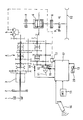
- Next, the invention will be described by means of an exemplifying embodiment with reference to the accompanying drawing. The only figure in the drawing is a fully schematic illustration of the power transmission system of a tractor or of a corresponding working machine, wherein the automatic system in accordance with the invention is employed for switching on/off of the transmission of the driving front axle.
- In the figure in the drawing, the engine of the tractor is denoted with the
reference numeral 1, the driving clutch with thereference numeral 2, and the gearbox generally with thereference numeral 4. Moreover, in the figure, it is indicated by means of thereference numeral 3 and the dashed-dotted line that, between the drivingclutch 2 and thegearbox 4, a so-called instant gearbox is provided, which has, as a rule, 2 to 4 different speed ranges. In the figure, the reference numeral 5 denotes the hydraulic pump, which is connected to a shaft which passes through thegearbox 4 and which is connected rigidly to theengine 1 of the tractor and which, thus, always revolves when theengine 1 runs. - From the
gearbox 4 the power is transmitted conventionally to the differential gear 6 of the rear axle, through the gear transmission in the gearbox on the drive-wheel shaft 7 of the rear axle. As is shown in the figure in the drawing, in the conventional way, the rear axle is provided withbrakes 8 as well as with a hub gear 9, e.g., of the planetary gear type. The figure shows one of therear wheels 10 only. Further, from thegearbox 4 the power is transmitted conventionally to thedrivewheel shaft 11 of the front axle and from there to the differential gear (not shown) of the front axle. Between the drive-wheel shaft 11 of the front axle and thegearbox 4, amulti-disk clutch 12 is fitted, by whose means the power transmission of the front axle can be switched on when required. Themulti-disk clutch 12 of the front axle is a hydraulically operated clutch, which is switched on and off, in accordance with the figure in the drawing, by means of the pressure supplied by the hydraulic pump 5 by the intermediate of thesolenoid valve 13. - The automatic arrangement in accordance with the invention for the transmission of the front axle includes a detector system, by whose means the control system in accordance with the invention judges the requirement of four-wheel drive in each particular situation. Firstly, the system includes a
speed detector 14, which measures the speed of rotation at the rear axle. In the figure in the drawing, saidspeed detector 14 for the rear axle is fitted in connection with thegearbox 4 to measure the speed of rotation of the drive-wheel shaft 7 of the rear axle so that the speed range of thegearbox 4 that is used does not affect the measurement result. Thespeed detector 14 of the rear axle may, however, be fitted in the system at any such point from which it is possible to measure either the speed of rotation of the rear axle directly or a speed of rotation that is proportional to the speed of the rear axle. Thus, the theoretical speed of the tractor is obtained as a measurement result given by thespeed detector 14 of the rear axle. Secondly, the system includes adetector 15 that indicates the speed of rotation of the transmission of the front axle, i.e. the speed detector of the front axle. Saidspeed detector 15 of the front axle is connected to the transmission so that it measures the speed at the front axle irrespective of whether the power transmission of the front axle is engaged or not. Further, the system includes aground speed detector 16, which indicates the ground speed and is based on microwaves, said detector measuring the factual travel speed of the tractor. Also, abraking detector 20 is connected to thebrake pedal 19 of the tractor, said detector indicating when the brake of the tractor is applied. - All of the
above detectors central unit 17 of the microprocessor type so that the detectors transmit the signals corresponding to the measurement data to saidcentral unit 17. Thesolenoid valve 13 that operates themulti-disk clutch 12 of the front axle is also connected to thecentral unit 17 so that thesolenoid valve 13 operates as controlled by thecentral unit 17. Thecentral unit 17 further includes a device by whose means the operator of the tractor can program the desired operation parameter for the control of the system. - The arrangement in accordance with the invention further includes an
operation switch device 18 for the driver, by whose means the mode of operation of the system can be selected. Theoperation switch device 18 includes switches by whose means it is chosen whether the driver wishes to use a fully manually controlled front-wheel drive or if a fully automatic operation is chosen. Positive control, i.e. manual control of the front-wheel drive, is needed when it is, out of some reason, desirable to force the front-wheel drive on or off irrespective of the automatic system. Thus, the manual-operation switch is an on-off switch, by whose means the front-wheel drive can be selected on or off. Thus, the switches of theoperation switch device 18 operate so that by means of one of the switches automatic/manual operation is chosen, whereas the other switch is for manual operation only, on and off. - For the
central unit 17 of the system, the operator programs the operation parameter that acts as the criterion for automatic switching-on of the power transmission for the front axle. This parameter is a simple percentage, which states the difference in speed between the front axle (drive-wheel shaft 11 of the front axle) and the rear axle (drive-wheel shaft 7 of the rear axle) as a percentage. When the power transmission of the front axle is engaged, this percentage is 0, and when therear wheels 10 revolve while the tractor does not move, this percentage is 100. Front-wheel drive is needed when, during operation, the percentage is higher than 10, inpractice 10...40, depending on the driving situation. - When the automatic operation has been switched on, the
central unit 17 starts calculating the corresponding factual percentage value and compares said value constantly with the desired reading. The factual value needed by the central unit is obtained by means of the signals given by thespeed detectors 
- The parameter P obtained from the formula given above states when the power transmission of the front axle must be switched on.
- In the following, the control algorithm present in the
central unit 17 will be described with the aid of an example: - When the tractor starts moving and after the automatic operation has been switched on by means of the
operation switch device 18, the control system has switched off the power transmission of the front axle. After this, themulti-disk clutch 12, which operates as the power transmission clutch of the front axle, is switched on as soon as the programmed operation parameter is exceeded, i.e. if the front-axle speed reported by thespeed detector 15 of the front axle is by a certain amount lower than the speed reported by thespeed detector 14 of the rear axle and if, at the same time, the ground speed reported by the ground-speed detector 16 is not excessively high. In such a case, the sign of the result of calculation is also taken into account, for, e.g., in a braking situation, the difference in speed may also be of opposite sign. In this way the system immediately notices if the slippage of the rear wheels becomes excessively high, in which case the system switches on the transmission of the front axle as an aid. The data on the factual speed of the tractor, provided by the ground-speed detector 16, are needed in order that thecentral unit 17 could tell whether the tractor is operating, e.g., on the road or on the field. If the factual speed is, for example, higher than 15 km per hour, the tractor is being operated on the road, and in such a case the front-wheel drive is not switched on at all. - Moreover, the system switches on the transmission of the front axle as soon as the brake pedal is pressed if the speed of the front axle is, at the same time, higher than 0 km per hour. The
braking detector 20 reports the depressing of thebrake pedal 19 to thecentral unit 17. By means of this switching, the braking is intensified, for normally the front wheels do not have brakes, and when the four-wheel drive is switched on, the grip of the front wheels can be utilized by means of the rear brakes. - The transmission of the front axle is switched off hereafter when the
brake pedal 19 is no longer depressed and when the factual speed of the tractor, reported by the ground-speed detector 16, is the same as the speed reported by thespeed detector 14 of the rear axle for a sufficiently long time (time constant programmed in the central unit 17) or when the factual speed of the tractor is excessively high (more than 15 km per hour) or when the speed reported by thespeed detector 14 of the rear axle is 0 km per hour, in which case the tractor has stopped or the rear wheels have been locked on braking. Further, the system switches off the transmission of the front axle when the ground speed, i.e. the factual speed, of the tractor is lower than a predetermined speed (15 km per hour) during braking when, during depression of thebrake pedal 19, the front-wheel drive was not engaged. - With the setting of conditions stated above, it is achieved that the transmission of the front axle is switched off as soon as the factual speed, i.e. the ground speed, of the tractor and the theoretical speed of the rear axle have been the same for a certain time, i.e. in a situation in which the wheels of the tractor do not slip and four-wheel drive is not needed. Further, according to the setting of conditions, if the speed of the tractor is increased beyond the permitted limit, the transmission of the front-wheel drive is switched off. The case is the same if the tractor stops or if, during braking, the speed has become lower than 15 km per hour and the four-wheel drive was not engaged before the braking speed. In the contrary case, of course, the automation will switch on the four-wheel drive automatically when the
brake pedal 19 is depressed. - Further, the transmission of the front axle is switched off if the
brake pedal 19 is depressed while, at the same time, the speed indicated by thespeed detector 14 of the rear axle is 0 km per hour and the ground speed is higher than 0 km per hour. This means that, on braking, the wheels of the tractor have been locked and steering of the tractor is impossible if the four-wheel drive is engaged. Now the system notices this and releases the transmission of the front axle as soon as locking occurs. The switching algorithm also immediately notices when the grip of the tires is restored and re-engages the transmission of the front axle. This property is also operative when manual control has been switched on. - The power transmission of the front axle is also switched off when it has been originally switched on and when the difference in speed between the speed reported by the
speed detector 15 of the front axle and the speed reported by thespeed detector 14 of the rear axle is higher than 0 for a certain time programmed in thecentral unit 17. By means of this switching, themulti-disk clutch 12 of the front axle is protected from failure, for, if slippage can occur in said clutch 12, it is destroyed very soon. When the coupling of the transmission of the front wheel is disengaged in such a case, the service life of the tractor is improved. The system operates in the same way both during braking and during acceleration. The operation is restored to normal after a certain delay programmed in the central unit. - Above, the invention has been described by way of example with reference to the exemplifying embodiment illustrated in the figure in the accompanying drawing. The invention is, however, not confined to the exemplifying embodiment illustrated in the figure alone, but different embodiments of the invention may show variation within the scope of the inventive idea defined in the accompanying claims.
Claims (12)
- Method for automatic switching on/off of the power transmission of a driving front axle of a tractor or of a corresponding working machine in a tractor or in a corresponding working machine which is provided with a power transmission system that includes an engine (1), a driving clutch (2), a gearbox (4), and a hydraulic pump (5), as well as a driving rear axle mechanically operated by means of the gearbox (4) as well as a transmission of the front axle to be coupled by means of a hydraulic coupling (12), characterized in that, in the method, the rear-axle speed, the front-axle speed, and the factual travel speed of the tractor or equivalent are measured constantly and a braking process is sensed, that the measured values and the point of time of the braking are compared with values and ranges of operation programmed in advance in the central unit (17) of the system, and that, when the measured values and the braking process are in a pre-determined relationship to the pre-programmed values and ranges of operation, depending on the situation, the transmission of the front axle is switched on/off automatically.
- Method as claimed in claim 1, characterized in that, in the method, from the measured axle speeds, the percentage ratio of the difference between the rear-axle speed and the front-axle speed to the measured rear-axle speed is calculated, that the calculated ratio is compared with a pre-programmed range of operation, and that the factual travel speed is compared with a pre-programmed speed value, the power transmission of the front axle being switched on when said percentage ratio exceeds the programmed value of range of operation while the factual travel speed is, at the same time, lower than the programmed value of travel speed.
- Method as claimed in claim 2, characterized in that the power transmission of the front axle is switched on when said percentage ratio of axle speeds is higher than the preset value and when the factual travel speed is at the maximum equal to the preset value.
- Method as claimed in claim 1, characterized in that the power transmission of the front axle is switched on during braking if the measured front-axle speed is higher than 0 km per hour.
- Method as claimed in claim 1 or 2, characterized in that the power transmission of the front axle is switched off if the factual travel speed and the measured rear-axle speed are equally high for a pre-determined period of time, unless braking occurs at the same time.
- Method as claimed in any of the claims 1 to 3, characterized in that the power transmission of the front axle is switched off if the factual travel speed is higher than a pre-programmed value of travel speed, unless braking occurs at the same time.
- Method as claimed in claim 6, characterized in that the power transmission of the front axle is switched off if the factual travel speed is higher than a preset value.
- Method as claimed in claim 1 or 4, characterized in that the power transmission of the front axle is switched off on braking if the measured front-axle speed is 0 km per hour and the ground speed is higher than 0 km per hour.
- Control system for automatic switching on/off of the power transmission of a driving front axle of a tractor or of a corresponding working machine in a tractor or in a corresponding working machine which is provided with a power transmission system that includes an engine (1), a driving clutch (2), a gearbox (4), and a hydraulic pump (5), as well as a driving rear axle mechanically operated by means of the gearbox (4) as well as a transmission of the front axle to be coupled by means of a hydraulic coupling (12), characterized in that the control system comprises a central unit (17), preferably of the microprocessor type, means (14,15,16) for constant measurement of the factual rear-axle speed, front-axle speed and travel speed of the tractor or working machine, as well as a detector device (20) for observation of a braking process, said means and devices (14,15,16,20) being arranged to feed the signals corresponding to the measured data to the central unit (17), in which unit limit-value ranges have been programmed in advance for the measured quantities, the central unit (17) being arranged to compare the measured data with the data pre-programmed in the central unit (17) so that, when the measurement data are in a predetermined relationship to the pre-programmed limit-value ranges, depending on the situation, the central unit (17) has been arranged to switch on/off the transmission of the front axle automatically.
- Control system as claimed in claim 9, characterized in that, based on the measured axle speeds, the central unit (17) is arranged to calculate the percentage ratio of the difference between the rear-axle speed and the front-axle speed to the measured rear-axle speed and to compare said calculated ratio with a pre-programmed value of operation range as well as to compare the factual travel speed with a pre-programmed speed value, the central unit (17) being arranged to switch on the power transmission of the front axle when said percentage ratio exceeds the programmed value of operation range while the factual travel speed is, at the same time, lower than the programmed value of travel speed.
- Control system as claimed in claim 9 or 10, characterized in that the control system further includes an operation switch device (18), by whose means the automatic control system can be switched on or, if necessary, by-passed.
- Control system as claimed in any of the claims 9 to 11, characterized in that the means (14,15) for measurement of the axle speeds comprise speed detectors, and that the device (20) for detection of the braking process comprises a switch detector of the on-off type, said detectors being arranged to feed the signals corresponding to the measurement data to the central unit (17).
Applications Claiming Priority (2)
| Application Number | Priority Date | Filing Date | Title |
|---|---|---|---|
| FI902397A FI90219C (en) | 1990-05-14 | 1990-05-14 | Method and system for automatically engaging / disengaging the transmission of the front axle of a tractor or implement |
| FI902397 | 1990-05-14 |
Publications (2)
| Publication Number | Publication Date |
|---|---|
| EP0457742A1 true EP0457742A1 (en) | 1991-11-21 |
| EP0457742B1 EP0457742B1 (en) | 1994-03-09 |
Family
ID=8530434
Family Applications (1)
| Application Number | Title | Priority Date | Filing Date |
|---|---|---|---|
| EP91850119A Expired - Lifetime EP0457742B1 (en) | 1990-05-14 | 1991-05-10 | Method and arrangement for automatic switching on/off of the power transmission of a driving front axle of a tractor or working machine |
Country Status (7)
| Country | Link |
|---|---|
| EP (1) | EP0457742B1 (en) |
| DE (1) | DE69101336T2 (en) |
| DK (1) | DK0457742T3 (en) |
| ES (1) | ES2050523T3 (en) |
| FI (1) | FI90219C (en) |
| NO (1) | NO300202B1 (en) |
| PT (1) | PT97618B (en) |
Cited By (4)
| Publication number | Priority date | Publication date | Assignee | Title |
|---|---|---|---|---|
| EP0510676A1 (en) * | 1991-04-26 | 1992-10-28 | Motor Sport Developments Ltd | Motor vehicle transmission control |
| EP0703109A1 (en) * | 1994-09-23 | 1996-03-27 | New Holland U.K. Limited | Modulated FWD clutch for tractor braking |
| WO2010118877A1 (en) * | 2009-04-17 | 2010-10-21 | Knorr-Bremse Systeme für Nutzfahrzeuge GmbH | Method for controlling a vehicle having only a braked rear axle and brake slip control |
| CN108466547A (en) * | 2018-05-25 | 2018-08-31 | 中联重机浙江有限公司 | A kind of tractor of stable transmission |
Families Citing this family (1)
| Publication number | Priority date | Publication date | Assignee | Title |
|---|---|---|---|---|
| DE102009053817C5 (en) † | 2009-11-18 | 2016-07-07 | Knorr-Bremse Systeme für Nutzfahrzeuge GmbH | Vehicle with braking torque from rear wheels to the front wheels transmitting brake device with brake slip control |
Citations (5)
| Publication number | Priority date | Publication date | Assignee | Title |
|---|---|---|---|---|
| DE3636260A1 (en) * | 1986-10-24 | 1988-05-05 | Opel Adam Ag | Motor vehicle with at least one permanently driven axle and an axle with engageable drive |
| EP0295738A1 (en) * | 1987-06-18 | 1988-12-21 | FIAT AUTO S.p.A. | A method for controlling the engagement and disengagement of an all-wheel drive in a vehicle |
| DE8813401U1 (en) * | 1987-10-26 | 1989-01-05 | Same S. P. A., Treviglio, It | |
| EP0315200A1 (en) * | 1987-11-05 | 1989-05-10 | Viscodrive Japan Ltd | Power transmission apparatus |
| EP0329045A2 (en) * | 1988-02-16 | 1989-08-23 | Deere & Company | Propulsion and braking device for a motor vehicle |
Family Cites Families (1)
| Publication number | Priority date | Publication date | Assignee | Title |
|---|---|---|---|---|
| IT1185865B (en) * | 1985-08-06 | 1987-11-18 | Alfa Romeo Auto Spa | CONTROL DEVICE FOR AN INTEGRAL DETACHABLE VEHICLE |
-
1990
- 1990-05-14 FI FI902397A patent/FI90219C/en active IP Right Grant
-
1991
- 1991-04-17 NO NO911504A patent/NO300202B1/en not_active IP Right Cessation
- 1991-05-09 PT PT97618A patent/PT97618B/en not_active IP Right Cessation
- 1991-05-10 EP EP91850119A patent/EP0457742B1/en not_active Expired - Lifetime
- 1991-05-10 DK DK91850119.8T patent/DK0457742T3/en active
- 1991-05-10 DE DE69101336T patent/DE69101336T2/en not_active Expired - Lifetime
- 1991-05-10 ES ES91850119T patent/ES2050523T3/en not_active Expired - Lifetime
Patent Citations (5)
| Publication number | Priority date | Publication date | Assignee | Title |
|---|---|---|---|---|
| DE3636260A1 (en) * | 1986-10-24 | 1988-05-05 | Opel Adam Ag | Motor vehicle with at least one permanently driven axle and an axle with engageable drive |
| EP0295738A1 (en) * | 1987-06-18 | 1988-12-21 | FIAT AUTO S.p.A. | A method for controlling the engagement and disengagement of an all-wheel drive in a vehicle |
| DE8813401U1 (en) * | 1987-10-26 | 1989-01-05 | Same S. P. A., Treviglio, It | |
| EP0315200A1 (en) * | 1987-11-05 | 1989-05-10 | Viscodrive Japan Ltd | Power transmission apparatus |
| EP0329045A2 (en) * | 1988-02-16 | 1989-08-23 | Deere & Company | Propulsion and braking device for a motor vehicle |
Cited By (6)
| Publication number | Priority date | Publication date | Assignee | Title |
|---|---|---|---|---|
| EP0510676A1 (en) * | 1991-04-26 | 1992-10-28 | Motor Sport Developments Ltd | Motor vehicle transmission control |
| EP0703109A1 (en) * | 1994-09-23 | 1996-03-27 | New Holland U.K. Limited | Modulated FWD clutch for tractor braking |
| WO2010118877A1 (en) * | 2009-04-17 | 2010-10-21 | Knorr-Bremse Systeme für Nutzfahrzeuge GmbH | Method for controlling a vehicle having only a braked rear axle and brake slip control |
| US8838356B2 (en) | 2009-04-17 | 2014-09-16 | Knorr-Bremse Systeme Fuer Nutzfahrzeuge Gmbh | Method for controlling a vehicle having only a braked rear axle and brake slip control |
| CN108466547A (en) * | 2018-05-25 | 2018-08-31 | 中联重机浙江有限公司 | A kind of tractor of stable transmission |
| CN108466547B (en) * | 2018-05-25 | 2024-02-23 | 中联重机浙江有限公司 | Tractor with stable transmission |
Also Published As
| Publication number | Publication date |
|---|---|
| NO911504D0 (en) | 1991-04-17 |
| PT97618B (en) | 1998-11-30 |
| DK0457742T3 (en) | 1994-06-27 |
| DE69101336T2 (en) | 1994-06-16 |
| FI902397A0 (en) | 1990-05-14 |
| EP0457742B1 (en) | 1994-03-09 |
| FI90219B (en) | 1993-09-30 |
| NO300202B1 (en) | 1997-04-28 |
| NO911504L (en) | 1991-11-15 |
| FI902397A (en) | 1991-11-15 |
| PT97618A (en) | 1993-05-31 |
| DE69101336D1 (en) | 1994-04-14 |
| ES2050523T3 (en) | 1994-05-16 |
| FI90219C (en) | 1994-01-10 |
Similar Documents
| Publication | Publication Date | Title |
|---|---|---|
| US5363938A (en) | Power transfer system for a four-wheel drive vehicle | |
| US5332060A (en) | Linear actuation mechanism for electronically-controlled torque modulated transfer case | |
| US5679085A (en) | Vehicle propulsion unit and method for controlling same | |
| US5655986A (en) | Full-time transfer case with synchronized single planetary gear reduction unit | |
| US5651749A (en) | Full-time transfer case with synchronized dual planetary gear reduction unit | |
| US5411110A (en) | Power transfer system for a four-wheel drive vehicle | |
| US4605087A (en) | All-wheel drive system for vehicles | |
| US4280583A (en) | Automatic differential control apparatus | |
| US5330030A (en) | Two-speed transfer case with electronic torque modulation | |
| US5582263A (en) | Full-time four wheel drive transfer case | |
| US20050217261A1 (en) | Drive system of a working vehicle | |
| US5655618A (en) | Torque modulated transfer case | |
| JPH07205674A (en) | Four wheel vehicle driving device and method of controlling delivery of torque in said device | |
| GB2167718A (en) | Improvements in or relating to transmission control arrangements of multiple axle driven vehicles | |
| EP0394390B1 (en) | Vehicle with multiple driven axles | |
| US4714127A (en) | Control apparatus for a vehicle with disengageable four-wheel drive | |
| US5247443A (en) | Electronic control for vehicle four wheel drive system | |
| US4773517A (en) | Torque control system for vehicles | |
| US6071207A (en) | Full-time transfer case with mode shift arrangement | |
| EP0212721B1 (en) | Control device for a vehicle with disengageable four-wheel drive | |
| US5695022A (en) | Double offset transfer case with electronically-controlled torque modulation | |
| US4890686A (en) | Drive mode selecting system for four-wheel-drive motor vehicle | |
| US5044458A (en) | Drive engagement for a selectively engageable wheelset | |
| EP0457742B1 (en) | Method and arrangement for automatic switching on/off of the power transmission of a driving front axle of a tractor or working machine | |
| US6644428B2 (en) | Automatic axle traction control |
Legal Events
| Date | Code | Title | Description |
|---|---|---|---|
| PUAI | Public reference made under article 153(3) epc to a published international application that has entered the european phase |
Free format text: ORIGINAL CODE: 0009012 |
|
| AK | Designated contracting states |
Kind code of ref document: A1 Designated state(s): DE DK ES FR GB IT SE |
|
| 17P | Request for examination filed |
Effective date: 19911016 |
|
| 17Q | First examination report despatched |
Effective date: 19920326 |
|
| GRAA | (expected) grant |
Free format text: ORIGINAL CODE: 0009210 |
|
| AK | Designated contracting states |
Kind code of ref document: B1 Designated state(s): DE DK ES FR GB IT SE |
|
| PG25 | Lapsed in a contracting state [announced via postgrant information from national office to epo] |
Ref country code: IT Free format text: LAPSE BECAUSE OF FAILURE TO SUBMIT A TRANSLATION OF THE DESCRIPTION OR TO PAY THE FEE WITHIN THE PRESCRIBED TIME-LIMIT;WARNING: LAPSES OF ITALIAN PATENTS WITH EFFECTIVE DATE BEFORE 2007 MAY HAVE OCCURRED AT ANY TIME BEFORE 2007. THE CORRECT EFFECTIVE DATE MAY BE DIFFERENT FROM THE ONE RECORDED. Effective date: 19940309 |
|
| REF | Corresponds to: |
Ref document number: 69101336 Country of ref document: DE Date of ref document: 19940414 |
|
| REG | Reference to a national code |
Ref country code: DK Ref legal event code: T3 |
|
| ET | Fr: translation filed | ||
| RAP2 | Party data changed (patent owner data changed or rights of a patent transferred) |
Owner name: VALMET TRAKTORI OY |
|
| REG | Reference to a national code |
Ref country code: GB Ref legal event code: 732E |
|
| REG | Reference to a national code |
Ref country code: ES Ref legal event code: PC2A Owner name: VALMET TRAKTORI OY |
|
| REG | Reference to a national code |
Ref country code: FR Ref legal event code: TP |
|
| PLBE | No opposition filed within time limit |
Free format text: ORIGINAL CODE: 0009261 |
|
| STAA | Information on the status of an ep patent application or granted ep patent |
Free format text: STATUS: NO OPPOSITION FILED WITHIN TIME LIMIT |
|
| EAL | Se: european patent in force in sweden |
Ref document number: 91850119.8 |
|
| 26N | No opposition filed | ||
| REG | Reference to a national code |
Ref country code: FR Ref legal event code: CA Ref country code: FR Ref legal event code: CD |
|
| REG | Reference to a national code |
Ref country code: ES Ref legal event code: PC2A |
|
| REG | Reference to a national code |
Ref country code: GB Ref legal event code: IF02 |
|
| REG | Reference to a national code |
Ref country code: GB Ref legal event code: 732E |
|
| REG | Reference to a national code |
Ref country code: FR Ref legal event code: CA Ref country code: FR Ref legal event code: TP Ref country code: FR Ref legal event code: CD |
|
| REG | Reference to a national code |
Ref country code: ES Ref legal event code: PC2A |
|
| PGFP | Annual fee paid to national office [announced via postgrant information from national office to epo] |
Ref country code: GB Payment date: 20100329 Year of fee payment: 20 |
|
| PGFP | Annual fee paid to national office [announced via postgrant information from national office to epo] |
Ref country code: ES Payment date: 20100503 Year of fee payment: 20 Ref country code: FR Payment date: 20100414 Year of fee payment: 20 |
|
| PGFP | Annual fee paid to national office [announced via postgrant information from national office to epo] |
Ref country code: DE Payment date: 20100520 Year of fee payment: 20 |
|
| PGFP | Annual fee paid to national office [announced via postgrant information from national office to epo] |
Ref country code: SE Payment date: 20100518 Year of fee payment: 20 |
|
| PGFP | Annual fee paid to national office [announced via postgrant information from national office to epo] |
Ref country code: DK Payment date: 20100825 Year of fee payment: 20 |
|
| REG | Reference to a national code |
Ref country code: DE Ref legal event code: R071 Ref document number: 69101336 Country of ref document: DE |
|
| REG | Reference to a national code |
Ref country code: DK Ref legal event code: EUP |
|
| REG | Reference to a national code |
Ref country code: GB Ref legal event code: PE20 Expiry date: 20110509 |
|
| REG | Reference to a national code |
Ref country code: SE Ref legal event code: EUG |
|
| PG25 | Lapsed in a contracting state [announced via postgrant information from national office to epo] |
Ref country code: GB Free format text: LAPSE BECAUSE OF EXPIRATION OF PROTECTION Effective date: 20110509 |
|
| REG | Reference to a national code |
Ref country code: ES Ref legal event code: FD2A Effective date: 20120220 |
|
| PG25 | Lapsed in a contracting state [announced via postgrant information from national office to epo] |
Ref country code: ES Free format text: LAPSE BECAUSE OF EXPIRATION OF PROTECTION Effective date: 20110511 |
|
| PG25 | Lapsed in a contracting state [announced via postgrant information from national office to epo] |
Ref country code: DE Free format text: LAPSE BECAUSE OF EXPIRATION OF PROTECTION Effective date: 20110510 |