EP0457540B1 - FCCU regenerator catalyst distribution system - Google Patents
FCCU regenerator catalyst distribution system Download PDFInfo
- Publication number
- EP0457540B1 EP0457540B1 EP91304293A EP91304293A EP0457540B1 EP 0457540 B1 EP0457540 B1 EP 0457540B1 EP 91304293 A EP91304293 A EP 91304293A EP 91304293 A EP91304293 A EP 91304293A EP 0457540 B1 EP0457540 B1 EP 0457540B1
- Authority
- EP
- European Patent Office
- Prior art keywords
- catalyst
- bed
- distribution system
- distributor
- spent catalyst
- Prior art date
- Legal status (The legal status is an assumption and is not a legal conclusion. Google has not performed a legal analysis and makes no representation as to the accuracy of the status listed.)
- Expired - Lifetime
Links
- 239000003054 catalyst Substances 0.000 title claims description 226
- 238000009826 distribution Methods 0.000 title claims description 39
- 230000008929 regeneration Effects 0.000 claims description 72
- 238000011069 regeneration method Methods 0.000 claims description 72
- 238000004231 fluid catalytic cracking Methods 0.000 claims description 10
- 238000007599 discharging Methods 0.000 claims description 4
- 230000003467 diminishing effect Effects 0.000 claims description 3
- 239000007789 gas Substances 0.000 description 55
- 238000006243 chemical reaction Methods 0.000 description 31
- 229930195733 hydrocarbon Natural products 0.000 description 17
- 150000002430 hydrocarbons Chemical class 0.000 description 17
- UGFAIRIUMAVXCW-UHFFFAOYSA-N Carbon monoxide Chemical compound [O+]#[C-] UGFAIRIUMAVXCW-UHFFFAOYSA-N 0.000 description 14
- 239000004215 Carbon black (E152) Substances 0.000 description 11
- QVGXLLKOCUKJST-UHFFFAOYSA-N atomic oxygen Chemical compound [O] QVGXLLKOCUKJST-UHFFFAOYSA-N 0.000 description 11
- 239000000571 coke Substances 0.000 description 11
- 239000003546 flue gas Substances 0.000 description 11
- 239000001301 oxygen Substances 0.000 description 11
- 229910052760 oxygen Inorganic materials 0.000 description 11
- 239000002245 particle Substances 0.000 description 11
- 239000007787 solid Substances 0.000 description 11
- 229910052799 carbon Inorganic materials 0.000 description 8
- 238000000034 method Methods 0.000 description 8
- 239000003921 oil Substances 0.000 description 8
- 238000004523 catalytic cracking Methods 0.000 description 7
- 238000005336 cracking Methods 0.000 description 7
- 230000000694 effects Effects 0.000 description 7
- 230000008569 process Effects 0.000 description 7
- OKTJSMMVPCPJKN-UHFFFAOYSA-N Carbon Chemical compound [C] OKTJSMMVPCPJKN-UHFFFAOYSA-N 0.000 description 5
- 238000002485 combustion reaction Methods 0.000 description 5
- 239000000203 mixture Substances 0.000 description 5
- 238000012546 transfer Methods 0.000 description 5
- IJGRMHOSHXDMSA-UHFFFAOYSA-N Atomic nitrogen Chemical compound N#N IJGRMHOSHXDMSA-UHFFFAOYSA-N 0.000 description 4
- 229910002091 carbon monoxide Inorganic materials 0.000 description 4
- 238000013461 design Methods 0.000 description 4
- 230000003628 erosive effect Effects 0.000 description 3
- 239000012530 fluid Substances 0.000 description 3
- JTJMJGYZQZDUJJ-UHFFFAOYSA-N phencyclidine Chemical class C1CCCCN1C1(C=2C=CC=CC=2)CCCCC1 JTJMJGYZQZDUJJ-UHFFFAOYSA-N 0.000 description 3
- CURLTUGMZLYLDI-UHFFFAOYSA-N Carbon dioxide Chemical compound O=C=O CURLTUGMZLYLDI-UHFFFAOYSA-N 0.000 description 2
- 238000010276 construction Methods 0.000 description 2
- 230000009849 deactivation Effects 0.000 description 2
- 238000010586 diagram Methods 0.000 description 2
- 239000003502 gasoline Substances 0.000 description 2
- 239000003701 inert diluent Substances 0.000 description 2
- 239000011261 inert gas Substances 0.000 description 2
- 239000007788 liquid Substances 0.000 description 2
- 229910052757 nitrogen Inorganic materials 0.000 description 2
- 238000012545 processing Methods 0.000 description 2
- 208000024891 symptom Diseases 0.000 description 2
- 230000032258 transport Effects 0.000 description 2
- MYMOFIZGZYHOMD-UHFFFAOYSA-N Dioxygen Chemical compound O=O MYMOFIZGZYHOMD-UHFFFAOYSA-N 0.000 description 1
- 241000282326 Felis catus Species 0.000 description 1
- UFHFLCQGNIYNRP-UHFFFAOYSA-N Hydrogen Chemical compound [H][H] UFHFLCQGNIYNRP-UHFFFAOYSA-N 0.000 description 1
- 239000000956 alloy Substances 0.000 description 1
- 229910045601 alloy Inorganic materials 0.000 description 1
- 239000010426 asphalt Substances 0.000 description 1
- 230000008901 benefit Effects 0.000 description 1
- 238000009835 boiling Methods 0.000 description 1
- 229910002092 carbon dioxide Inorganic materials 0.000 description 1
- 239000001569 carbon dioxide Substances 0.000 description 1
- 239000003575 carbonaceous material Substances 0.000 description 1
- 230000003197 catalytic effect Effects 0.000 description 1
- 239000000919 ceramic Substances 0.000 description 1
- 239000003245 coal Substances 0.000 description 1
- 239000000567 combustion gas Substances 0.000 description 1
- 239000010779 crude oil Substances 0.000 description 1
- 230000007423 decrease Effects 0.000 description 1
- 230000008021 deposition Effects 0.000 description 1
- 239000003085 diluting agent Substances 0.000 description 1
- 229910001882 dioxygen Inorganic materials 0.000 description 1
- 239000006185 dispersion Substances 0.000 description 1
- 238000005243 fluidization Methods 0.000 description 1
- 239000000446 fuel Substances 0.000 description 1
- 238000010438 heat treatment Methods 0.000 description 1
- 239000001257 hydrogen Substances 0.000 description 1
- 229910052739 hydrogen Inorganic materials 0.000 description 1
- 238000005984 hydrogenation reaction Methods 0.000 description 1
- 238000012423 maintenance Methods 0.000 description 1
- 239000000463 material Substances 0.000 description 1
- 229910052751 metal Inorganic materials 0.000 description 1
- 239000002184 metal Substances 0.000 description 1
- 150000002739 metals Chemical class 0.000 description 1
- 238000002156 mixing Methods 0.000 description 1
- 238000012986 modification Methods 0.000 description 1
- 230000004048 modification Effects 0.000 description 1
- 230000001737 promoting effect Effects 0.000 description 1
- 230000009467 reduction Effects 0.000 description 1
- 230000001172 regenerating effect Effects 0.000 description 1
- 230000000630 rising effect Effects 0.000 description 1
- 239000003079 shale oil Substances 0.000 description 1
- 239000011949 solid catalyst Substances 0.000 description 1
- 238000003466 welding Methods 0.000 description 1
Images


Classifications
-
- C—CHEMISTRY; METALLURGY
- C10—PETROLEUM, GAS OR COKE INDUSTRIES; TECHNICAL GASES CONTAINING CARBON MONOXIDE; FUELS; LUBRICANTS; PEAT
- C10G—CRACKING HYDROCARBON OILS; PRODUCTION OF LIQUID HYDROCARBON MIXTURES, e.g. BY DESTRUCTIVE HYDROGENATION, OLIGOMERISATION, POLYMERISATION; RECOVERY OF HYDROCARBON OILS FROM OIL-SHALE, OIL-SAND, OR GASES; REFINING MIXTURES MAINLY CONSISTING OF HYDROCARBONS; REFORMING OF NAPHTHA; MINERAL WAXES
- C10G11/00—Catalytic cracking, in the absence of hydrogen, of hydrocarbon oils
- C10G11/14—Catalytic cracking, in the absence of hydrogen, of hydrocarbon oils with preheated moving solid catalysts
- C10G11/18—Catalytic cracking, in the absence of hydrogen, of hydrocarbon oils with preheated moving solid catalysts according to the "fluidised-bed" technique
- C10G11/182—Regeneration
-
- B—PERFORMING OPERATIONS; TRANSPORTING
- B01—PHYSICAL OR CHEMICAL PROCESSES OR APPARATUS IN GENERAL
- B01J—CHEMICAL OR PHYSICAL PROCESSES, e.g. CATALYSIS OR COLLOID CHEMISTRY; THEIR RELEVANT APPARATUS
- B01J8/00—Chemical or physical processes in general, conducted in the presence of fluids and solid particles; Apparatus for such processes
- B01J8/0015—Feeding of the particles in the reactor; Evacuation of the particles out of the reactor
Definitions
- the present invention relates to the regeneration of catalysts employed in a fluid catalytic cracking process. More particularly, this invention relates to the introduction of spent catalyst into a regeneration zone by means of a catalyst distribution system comprising stationary distributor arms. A further aspect of the invention relates to the discharge of regenerated catalyst from the regeneration zone by means of a collection system comprising a shrouded catalyst outlet.
- the fluidized catalytic cracking of hydrocarbons is well known in the prior art and may be accomplished by a variety of processes which employ fluidized solid techniques. Normally in such processes, preheated, relatively high molecular weight hydrocarbon liquids and/or vapors are contacted with hot, finely-divided, solid catalyst particles either in a fluidized bed reaction zone or in an elongated riser reaction zone. The mixture of hydrocarbons and catalyst is maintained at an elevated temperature in a fluidized state for a period of time sufficient to effect the desired degree of cracking to lower molecular weight hydrocarbons typical of those present in motor gasolines and distillate fuels.
- a typical regeneration zone comprises a large vertical substantially cylindrical vessel wherein the spent catalyst is maintained as a fluidized bed by the upward passage of an oxygen-containing regeneration gas such as air.
- the fluidized catalyst forms a dense phase catalyst bed in the lower portion of the vessel and a dilute catalyst phase containing entrained catalyst particles above, with an interface existing between the two phases.
- the catalyst is contacted with the oxygen-containing regeneration gas under conditions sufficient to burn at least a portion, preferably a major portion, of the coke from the catalyst.
- Flue gas which normally comprises gases arising from the combustion of the coke on the spent catalyst, inert gases such as nitrogen from air, any unconverted oxygen, and entrained catalyst particles, are then passed from the dilute catalyst phase into solid-gas separators within the regeneration zone (e.g., cyclone separators) to prevent excessive losses of the entrained catalyst particles.
- the catalyst particles separated from the flue gas are returned to the dense phase catalyst bed.
- the regenerated catalyst is subsequently withdrawn from the regeneration zone and re-introduced into the reaction zone for reaction with additional hydrocarbon feed.
- spent catalyst typically enters the regenerator vessel through a riser, or vertical conduit, which terminates just above a grid. It is known to deflect the incoming catalyst flow by means of a flat plate above the riser outlet. However, there is usually no positive distribution of the incoming catalyst throughout the bed. As a result of incomplete distribution, concentration gradients of the gases leaving the regenerator bed are produced and localized afterburning, in the cyclones above the riser or above the overflow well, may occur.
- an overflow well to collect regenerated catalyst from the regenerator bed for return to the reaction zone.
- Such an overflow well also provides for control of bed height, particularly if gas/solids in-flow perturbations occur.
- the conventional overflow well is subject to certain problems. Typically, in a fluidized bed such as in the regenerator, both dense phase solids and also regions of lower density "bubbles" rise through the bed, with phase disengagement occurring at the top of the bed. It is known that the bubbles rising through the regenerator bed, 95% of gas flow, have a particle wake and tend to drag catalyst to the top of the bed very quickly. The catalyst particles then gradually migrate downward in the bed.
- a conventional overflow well can be fed by high-carbon spent catalyst that has been brought to the top by the bubbles. It is known to shield the overflow well or catalyst outlet from the top of the bed by a shroud, so to prevent somewhat this bypassing.
- the entry to the space above the overflow well is selected to provide the lowest-carbon catalyst, and the top of the shroud is restricted to reduce the amount of entrained catalyst entering.
- Prior art shrouds are shown in commonly assigned U.S. patents 3,902,990 and 3,958,953.
- Solids distributors have been used outside the field of the invention.
- U.S. patent 3,784,108 discloses the use of equal rotating radial arms for distributing solids in a fluid bed combustor.
- U.S. patent teaches a rotating radial arm feed device. These prior art devices have arms that rotate, whereas the subject invention employs a plurality of stationary arms.
- the Kellogg Company is believed to employ spent catalyst distributors in their catalytic cracking units, although the specific details are not public to applicant's knowledge.
- An object of the present invention is therefore to provide an apparatus for maximizing the dispersion and distribution of the catalyst in the regeneration zone of a fluid catalytic cracking unit, so to prevent both catalyst dead spots and by-passing of the bed, and to thereby achieve sufficient residence time for the desired regeneration of spent catalyst.
- AU-B-511,590 describes a spent catalyst regenerator fitted with a catalyst distributing means in the form of a well pipe surrounding a central stand pipe.
- Distributor arms of U cross-section extend from notches in the well pipe in an upper region of the bed or above its normal level and are downwardly directed with open ends.
- Steam conduits extending along the arms direct steam upwardly through nozzles to at least partially fluidize the catalyst in the arms so that at least part of the catalyst is expelled at various points along each of the arms.
- EP-A-0 289 991 describes a regenerator with a catalyst distributing means of generally similar construction with downwardly extending troughs surrounding a lift well. However it appears that although fluidising air is injected into the troughs, the fluidised catalyst flows out at the ends of the troughs.
- the invention provides a spent catalyst distribution system for a fluid catalytic cracking regeneration vessel having a bed of spent catalyst and a grid positioned below the spent catalyst bed for distributing gas which fluidises and regenerates the spent catalyst, said distribution system being arranged for distributing spent catalyst into the regeneration vessel, characterised in that said distribution system comprises at least one elongated distributor means having a proximal end connected to a spent catalyst inlet conduit and a distal end, said at least one distributor means introducing and evenly distributing catalyst and admixed gas into the regeneration vessel, wherein said at least one distributor means comprises a respective bottom piece extending from said proximal end to said distal end thereby defining at least one channel having at least one elongated slot, said at least one channel restricting the catalyst and admixed gas discharge and forcing flow out through at least one said elongated slot and towards the distal end of the at least one distributor means, each distal end having means to block the further flow of spent catalyst and admitted gas.
- said distribution system comprises at least one
- the invention is inclusive of fluid catalytic cracking regeneration vessel having a bed of spent catalyst, a grid positioned below the spent catalyst bed for distributing gas which fluidises and regenerates the spent catalyst, and a spent catalyst distribution system as described above arranged for distributing spent catalyst into the regeneration vessel.
- the regeneration vessel includes a regenerator catalyst collection system comprising a substantially cylindrical shroud concentrically surrounding a top portion (e.g. in the form of a funnel-shaped overflow well) of a vertical regenerated catalyst outlet conduit, wherein said shroud is disposed in relation to said conduit so as to form an essentially downwardly facing annular slot between the outlet conduit and the shroud through which the regenerated catalyst exits the bed, in operation, and further comprising a substantially circular opening at the top portion of the shroud to permit the level of the bed to remain uniform.
- a regenerator catalyst collection system comprising a substantially cylindrical shroud concentrically surrounding a top portion (e.g. in the form of a funnel-shaped overflow well) of a vertical regenerated catalyst outlet conduit, wherein said shroud is disposed in relation to said conduit so as to form an essentially downwardly facing annular slot between the outlet conduit and the shroud through which the regenerated catalyst exits the bed, in operation, and further comprising a substantially circular opening at the
- the regeneration vessel further comprises a plurality of openings circumferentially formed along the sides of the shroud beneath the level of said bed so that in operation the regenerated catalyst in the regenerator bed exits via either said openings or via said annular slot, between the outlet conduit and said shroud.
- the mechanical devices disclosed herein contribute to optimal catalyst distribution in the regenerator bed and avoid catalyst short-circuiting or dead spots. They also permit more even distribution of the regeneration gas (preventing afterburning) and minimize entrainment of unreacted catalyst.
- FIGS. 1 and 2 first illustrate typical prior art fluid catalytic cracking units to which the present invention is applicable.
- Various items such as valves, pumps, compressors, steam lines, instrumentation and other process equipment and control means have been omitted from the figures for the sake of simplicity.
- Hydrocarbon feedstocks that can be suitably employed in a fluid catalytic cracking process include naphthas, light gas oils, heavy gas oils, wide-cut gas oils, vacuum gas oils, kerosenes, decanted oils, residual fractions, reduced crude oils, cycle oils derived from any of these, as well as suitable fractions derived from shale oil kerogen, tar sands bitumen processing, synthetic oils, coal hydrogenation, and the like.
- Such feedstocks may be employed singly, separately in parallel reaction zones, or in any desired combination.
- Hydrocarbon gas and vapors passing through fluid bed 12 maintain the bed in a dense turbulent fluidized condition having the appearance of a boiling liquid.
- the hydrocarbon product After passing through cyclones 48, wherein entrained catalyst particles are returned to the bed via diplegs 50, the hydrocarbon product, in vapor or gas form, exits the reactor through conduit 52.
- the cracking catalyst becomes spent during contact with the hydrocarbon feedstock due to the deposition of coke thereon.
- the terms "spent” or “coke-contaminated” catalyst as used herein generally refer to catalyst which has passed through a reaction zone and which contains a sufficient quantity of coke thereon to cause activity loss to an extent requiring regeneration.
- the coke content of spent catalyst can vary anywhere from about 0.5 to about 5 wt. % or more.
- spent catalyst coke content varies from about 0.5 to about 1.5 wt. %.
- the spent catalyst Prior to actual regeneration, the spent catalyst is usually passed from the reaction zone into a stripping zone 18 and contacted therein with a stripping gas, which is introduced into the lower portion of zone 18 via line 20.
- the stripping gas serves to remove most of the volatile hydrocarbons from the spent catalyst.
- a preferred stripping gas is steam, although nitrogen, other inert gases or flue gas may be employed.
- Stripped spent catalyst from which most of the volatile hydrocarbons have been stripped is then passed from the bottom of stripping zone 18, through a spent catalyst transfer line, such as U-bend 22 and interconnected vertical riser 24, which extends into the lower portion of a regeneration zone 26.
- a spent catalyst transfer line such as U-bend 22 and interconnected vertical riser 24, which extends into the lower portion of a regeneration zone 26.
- Riser 24 is shown entering regeneration zone 26 off-center to avoid interference with the auxiliary heating air from section 31 of the regeneration zone. Air is added to riser 24 through line 41 and line 28 in an amount sufficient to reduce the density of the catalyst flowing therein, thus causing the catalyst to flow upward into the regeneration zone 26 by simple hydraulic balance.
- the regeneration zone is in a separate vessel (arranged at approximately the same level as reaction zone 10) containing a dense phase catalyst bed 30 having a level indicated at 32, above which is a dilute catalyst phase 34.
- the catalyst in the dense phase catalyst bed 30 undergoes regeneration to burn off coke deposits formed in the reaction zone during the cracking reaction.
- An oxygen-containing regeneration gas enters the lower portion of regeneration zone 26 via line 36 and passes up through a grid 38 and the dense phase catalyst bed 30, maintaining said bed in a turbulent fluidized condition similar to that present in reaction zone 10.
- the regenerator shown in FIG. 1 is improved by the present invention, as will be discussed in more detail hereinbelow.
- the present invention resides in modifying the regenerator portion of the catalytic cracking system of FIG. 1 by passing the spent catalyst entering the regenerator through a distribution system comprising at least one distributor arm and also passing the regenerated catalyst through a collection system prior to exiting the regenerator.
- flue gases formed in regeneration zone 26 during regeneration of the spent catalyst pass from the dense phase catalyst bed 30 into the dilute catalyst phase 34 along with entrained catalyst particles.
- the catalyst particles are separated from the flue gas by a suitable gas-solid separators 54 and returned to the dense phase catalyst bed 30 via diplegs 56.
- the substantially catalyst-free flue gas then passes into a plenum chamber 58 prior to discharge from the regeneration zone 26 through line 60.
- the flue gas will contain less than about 0.2, preferably less than 0.1, and more preferably less than 0.05 volume % carbon monoxide. However, in partial combustion operation, the carbon monoxide content may increase to about 8 to 13 percent.
- the oxygen content will vary from about 0.4 to about 7 vol. %, preferably from about 0.8 to about 5 vol. %, more preferably from about 1 to about 3 vol. %, most preferably from about 1.0 to about 2 vol. %.
- the regenerated catalyst is returned to the reactor via line 42.
- Oxygen-containing regeneration gases which may be employed in the process of the present invention are those gases which contain molecular oxygen in admixture with a substantial portion of an inert diluent gas.
- Air is a particularly suitable regeneration gas.
- air enriched with oxygen may be employed.
- steam may be added to the dense phase bed along with the regeneration gas or separately therefrom to provide additional inert diluents and/or fluidization gas.
- the specific vapor velocity of the regeneration gas will be in the range of from 0.24 to 1.83 m/s (0.8 to 6.0 feet/sec), preferably from 0.4 to to 1.22 m/s (1.5 to 4 feet/sec).
- a riser reaction zone 110 comprises a tubular, vertically extending vessel having a relatively large height in relation to its diameter.
- Reaction zone 110 communicates with a disengagement zone 120, shown located a substantial height above a regeneration zone 150.
- the catalyst circulation rate is controlled by a valve means, such as slide valve 180, located in spent catalyst transfer line 142 extending between disengagement zone 120 and regeneration zone 150.
- hydrocarbon feedstock is injected through line 112 into riser reaction zone 110 having a fluidized bed of catalyst to catalytically crack the feedstock.
- Steam may be injected through line 160 into return line 158 extending between regeneration zone 150 and reaction zone 110 to serve as a diluent, to provide a motive force for moving the hydrocarbon feedstock upwardly and for keeping the catalyst in a fluidized condition.
- the vaporized, cracked feedstock products pass upwardly into disengagement zone 120 where a substantial portion of the entrained catalyst is separated.
- the gaseous stream then passes through a gas-solid separator, such as two stage cyclone 122, which further separates out entrained catalyst and returns it to the disengagement zone through diplegs 124 and 126.
- the gaseous stream passes into plenum chamber 132 and exits through line 130 for further processing (not shown).
- the upwardly moving catalyst in reaction zone 110 gradually becomes coated with carbonaceous material which decreases its catalytic activity.
- reaction zone 110 When the catalyst reaches the top of reaction zone 110, it is redirected by grid 128 into stripping zone 140 and subsequently into spent catalyst transfer line 142, where it is contacted by a stripping gas, such as steam, entering through line 144, to partially remove the remaining volatile hydrocarbons from the spent catalyst.
- the spent catalyst then passes through spent catalyst transfer line 192 into dense phase catalyst bed 162 of regeneration zone 150.
- Oxygen containing regeneration gas enters dense phase catalyst bed 162 through line 164 to maintain the bed in a turbulent fluidized condition, similar to that in riser reaction zone 110.
- Regenerated catalyst gradually moves upwardly through dense phase catalyst bed 162, eventually flowing into a conventional overflow well 156 communicating with return line 158.
- Return line 158 is shown exiting through the center of dense phase catalyst bed 162, and communicating with riser reaction zone 110.
- Flue gas formed during the regeneration of the spent catalyst passes from the dense phase catalyst bed 152 into dilute catalyst phase 154.
- the flue gas then passes through cyclone 170 into plenum chamber 172 prior to discharge through line 174.
- Catalyst entrained in the flue gas is removed by cyclone 170 and is returned to catalyst bed 162 through diplegs 176, 178.
- the regeneration zone normally comprises a vertical generally cylindrical vessel wherein the catalyst to be regenerated is maintained as a fluidized bed by the upward passage of the oxygen-containing regeneration gas thereby forming, as mentioned above, a dense phase catalyst bed and a dilute catalyst phase with an interface in-between.
- the dense phase bed which is usually located in the lower portion of the regeneration zone, is maintained at a temperature in the range of from 621 to 760°C (1150° to 1400° F), preferably from 677 to 716°C (1250° to 1320° F).
- the density of the dense phase bed may suitably range from 128 to 480 kg/m3 (8 to 30 lb/ft3).
- the construction of the regeneration zone equipment described herein can be made with any material sufficiently able to withstand the relatively high temperatures involved if afterburning is encountered within the vessel and the high attrition conditions which are inherent in systems wherein fluidized catalyst is regenerated and transported.
- metals are contemplated which may or may not be lined.
- ceramic liners are contemplated within any and all portions of the regeneration zone together with alloy use and structural designs in order to withstand the erosive conditions and temperatures of about 760°C (1400° F) and, for reasonably short periods of time, temperatures which may be as high as 982°C (1800° F).
- the pressure in the regeneration zone is usually maintained in a range from about atmospheric to about 0.345 MPa (50 psig), preferably from 0.069 to 0.345 MPa (10 to 50 psig). It is preferred, however, to design the regeneration zone to withstand pressures of up to about 0.69 MPa (100 psig). Operation of the regeneration zone at increased pressure has the effect of promoting the conversion of carbon monoxide to carbon dioxide and reducing the temperature level within the dense bed phase at which the substantially complete combustion of carbon monoxide can be accomplished. The higher pressure also lowers the equilibrium level of carbon on regenerated catalyst at a given regeneration temperature.
- the residence time of the spent catalyst in the regeneration zone suitably can vary from about 1 to about 6 minutes; typically, from about 2 to about 4 minutes.
- the residence time of the flue gas may vary from about 10 to about 60 seconds in the regeneration zone and from about 2 to about 15 seconds in the dense phase bed.
- FIG. 3 showing in detail a portion of a regenerator 62 within a regenerator shell or wall 100.
- Spent catalyst from a stripping zone (not shown) is introduced via inlet riser conduit 70 into a dense phase catalyst bed 61, having a bed level 63.
- Regenerated catalyst from the dense phase catalyst bed 61 flows downward through a standpipe 86.
- regenerated catalyst is meant catalyst leaving the regeneration zone which has contacted an oxygen-containing gas causing at least a portion, preferably a substantial portion, of the coke present on the catalyst to be removed. More specifically, the carbon content of the regenerated catalyst can vary anywhere from about 0.01 to about 0.5 wt. %, but preferably is from about 0.01 to about 0.1 wt. percent.
- the spent catalyst is evenly introduced into the regenerator bed through a cap 68, suitably frusto conical in shape, which covers the spent catalyst riser outlet near grid 90 at the bottom of the regenerator bed.
- This grid 90 typically has an even hole distribuiton.
- the cap 68 has several arm-like extensions 64, 65, and 66, hereafter referred to as distributor arms, which duct the incoming spent catalyst and evenly discharge it through the bed.
- the bottom of each of the arms are provided with one or more inverted open channels which restrict the catalyst discharge and force flow to the end of each arm.
- a distributor arm 64 is shown in side-view.
- a proximate end portion 67 is shown connected to the cap 68 covering the inlet riser conduit 70, which conduit in operation transports spent catalyst into the regenerator 62.
- a vapor stop 72 blocks further flow of catalyst.
- the bottom edge 74 of the distributor arm 64 is shown toothed or serrated along its length to assist in the more even discharge of catalyst and gas at a range of inflowing rates.
- the distributor arm is seen to have a triangular cross-section with sides 76 and 78. This shape prevents dead catalyst zones from forming above the arms, which can result in catalyst deactivation.
- cracking catalysts typically have an angle of repose of about 78 degrees.
- a bottom piece 80 extends along a length of the arm and defines a continuous channel connected to elongated outlet slots 82 and 84 for discharge of catalyst and admixed gases. As evident, the slots face downward and are dimensioned to ensure that the gas is propelled out, but not so high that erosion occurs.
- a slot and/or channel may be wider at its end and narrower at its beginning to take into account the diminishing velocity of the gas as it escapes through the outlet slot.
- the toothed or serrated notched edge produces a uniform weir effect, wherein the gas flows out the riser conduit at a sufficiently high velocity.
- the velocity of the gas, entering the regenerator admixed with catalyst is about 3.05 m/s (10 ft/sec).
- the density of the solids stream is 160 to 400 kg/m3 (10 to 25 lb/ft3). In strictly dense phase flow, the density would be close to 720 kg/m3 (45 lb/ft3). This density range is the reason the present does not require a rotating means. There is enough gas admixed with the solids to insure distribution through the apparatus.
- a regenerator catalyst collection system is also shown, wherein a regenerated catalyst outlet conduit 86 is concentrically surrounded and partially covered by a substantially cylindrical baffle or shroud generally designated 88.
- the shroud can be supported by posts (not shown) connected to the grid, outlet conduit and/or wall of the regenerator.
- a number of catalyst entry holes 91 are shown on the side of the shroud.
- the catalyst in the regenerator bed can also exit via a downwardly facing annular aperature or slot 92 surrounding a funnel shaped extension of the outlet conduit 86.
- a substantially circular opening 94 at the top portion of the shroud 88 permits the level of the bed 63 to remain uniform.
- FIG. 4 shows the regenerator 62 of FIG. 3 in plan-view. Illustrative grid holes 96 are shown, which distribute the incoming regeneration air.
- a plurality of spent catalyst distributor arms 64, 65 and 66 are seen to radiate from the conical cap 68.
- each of the arms is in the form of a blade extending from the conical cap 68 and having an elongated channel extending longitudinally of the arm, as discussed with regard to FIGS. 3 and 6.
- Two elongated outlet slots may be co-extensive with said channel or there may be a series of shorter slots for the discharge of the catalyst and affixed gas.
- Each arm may extend radially of the conical cap perpendicularly to the axis thereof.
- each arm may radiate from the axis of the cap at an angle thereto.
- a downwardly sloping distributor arm prevents solids from settling out within the arm. It is also possible to have a ring section (not shown) connecting a plurality of arms.
- each of the above-mentioned catalyst distributor arms are attached to the conical cap in a moving or sliding joint connected by a flange.
- This is preferable to a mechanical design involving welding, since mechanical forces can cause cracks which shorten run lengths. If there is no reason to join or weld an edge, then flexibiltiy and simplicity of design are preferred.
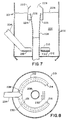
- FIG. 7 shows application of the present invention to the type of catalytic cracking unit in FIG. 2.
- a regenerator zone 201 within a regenerator wall 202 has a dense phase fluidized bed 200 of level 206.
- Spent catalyst from a stripping zone (not shown) is introduced into the dense phase catalyst bed 200 of the regeneration zone via inlet conduit 204, which is shown entering the left side of the regenerator wall 202.
- Regenerated catalyst from the dense phase catalyst bed 200 of regeneration zone 201 flows downward through a central standpipe 208.
- the spent catalyst is evenly introduced into the bed through a split annular ring 210 which partially surrounds the central regenerated catalyst standpipe 208 transversing grid 212 at the bottom of the regenerator bed.
- This part-annular ring 210 forms one or more part-annular ducts for transporting and evenly discharging the incoming spent catalyst through the bed.
- the bottom of the distributor ring is provided with at least one inverted channel for restricting the catalyst discharge and forcing flow to the two ends of the ring.
- the bottom edges 218 of the sides of the ring may be provided with notches to assist in the more even discharge of catalyst and gas at lower inflowing rates.
- the distributor ring 210 is shown connected at proximal ends 209 to the inlet conduit 204, which in operation transports spent catalyst into the regenerator bed 200.
- FIG. 8 shows the regenerator zone 201 of FIG. 7 in plan view. Illustrative grid holes 230 can be seen, which distribute the incoming regeneration air.
- the catalyst distribution ring 210 can be seen to extend from the inlet conduit 204.
- the ring 210 defines at least one open channel, which extends longitudinally the length of each side of the ring 210, which channel communicates with elongated apertures or outlet slots 230 and 231 which are at least partially co-extensive with the channel.
- the ring 210 may have a series of shorter slots for the discharge of the catalyst and air.
- the channel is preferably closed at the bottom.
- the two distal ends of the distributor ring 210 have vapor stops 214 and 216 to block further flow.
- the bottom edge 218 of the distributor ring may be toothed along its length.
- the ring distributor may have a triangular cross-section to prevent dead catalyst zones from forming above the ring.
- a bottom piece 232 may also extend along the length of the ring to define two slots for discharge of catalyst and air or other gas. The slots face downward and are dimensioned to ensure that the gas is propelled out, but not so high that erosion occurs.
- the channel and/or slots may be wider at the ends of the ring channel and narrower at the beginning of the channel to take into account the diminishing velocity of the gas as it escapes through the outlet slots.
- a regenerator catalyst collection system is also shown in FIG. 7, wherein a regenerated catalyst outlet conduit 208 is surrounded and partially covered by a substantially cylindrical shroud generally designated 222.
- the catalyst in the regenerator bed may exit via an annular space 224 and 225 surrounding the outlet funnel shaped portion 226 of the outlet conduit 208.
- a substantially circular opening 228 at the top portion of the shroud permits the level of the bed to remain uniform.
- the present invention can provide a significant reduction of carbon on regenerated catalyst. Since every 0.1 wt. % carbon on catalyst is equal to a gasoline yield loss of about 1 vol. % on feed, there is considerable potential for improved regenerator operation by means of the present invention.
- the present invention also permits reduced regenerator holdup. This will result in lower catalyst costs due to better activity maintenance, as well as increased unit capacity due to lower bed pressure drop which adds to blower capacity.
- a further advantage of the invention is that the gas which is admixed with the spent catalyst is more evenly distributed into the bottom of the bed, which prevents afterburning.
- This gas has a small quantity of hydrocarbon which has a high hydrogen content.
- the combustion gases leaving the bed would have different compositions in different areas. If these compositions were such that there were excess oxygen in one zone and excess CO in other zones, these gases would mix in the dilute phase and afterburning would result. This afterburning would result in excessive temperatures, as there is little catalyst to absorb the heat release.
- the present invention may be applied beneficially to a variety of types of fluid cat cracking units with little or no modifications and without limitations as to the spatial arrangement of the reaction, stripping, and regeneration zones thereof.
- the regeneration zone of a catalytic cracking unit can be designed independently from the reaction zone, since the regeneration zone merely receives spent catalyst, oxidizes the coke thereon to regenerate the catalyst, and returns the regenerated catalyst to the reaction zone. Therefore, the reaction zone can be a pure transfer line, i.e., one in which the reaction occurs in a single pipe type vessel directly terminating in a rough cut cyclone or cyclones as in Fig. 2, a conventional dilute riser/dense bed combination as in Fig. 1, or a dense bed alone.
Landscapes
- Chemical & Material Sciences (AREA)
- Organic Chemistry (AREA)
- Chemical Kinetics & Catalysis (AREA)
- Oil, Petroleum & Natural Gas (AREA)
- Engineering & Computer Science (AREA)
- General Chemical & Material Sciences (AREA)
- Production Of Liquid Hydrocarbon Mixture For Refining Petroleum (AREA)
- Devices And Processes Conducted In The Presence Of Fluids And Solid Particles (AREA)
- Catalysts (AREA)
Description
- The present invention relates to the regeneration of catalysts employed in a fluid catalytic cracking process. More particularly, this invention relates to the introduction of spent catalyst into a regeneration zone by means of a catalyst distribution system comprising stationary distributor arms. A further aspect of the invention relates to the discharge of regenerated catalyst from the regeneration zone by means of a collection system comprising a shrouded catalyst outlet.
- The fluidized catalytic cracking of hydrocarbons is well known in the prior art and may be accomplished by a variety of processes which employ fluidized solid techniques. Normally in such processes, preheated, relatively high molecular weight hydrocarbon liquids and/or vapors are contacted with hot, finely-divided, solid catalyst particles either in a fluidized bed reaction zone or in an elongated riser reaction zone. The mixture of hydrocarbons and catalyst is maintained at an elevated temperature in a fluidized state for a period of time sufficient to effect the desired degree of cracking to lower molecular weight hydrocarbons typical of those present in motor gasolines and distillate fuels.
- During the cracking reaction, coke is deposited on the catalyst particles in the reaction zone, thereby reducing the activity of the catalyst for cracking and the selectivity of the catalyst for producing gasoline blending stock. In order to restore a portion, preferably a major portion, of the activity to the coke contaminated or spent catalyst, the catalyst is transferred from the reaction zone into a regeneration zone. A typical regeneration zone comprises a large vertical substantially cylindrical vessel wherein the spent catalyst is maintained as a fluidized bed by the upward passage of an oxygen-containing regeneration gas such as air. The fluidized catalyst forms a dense phase catalyst bed in the lower portion of the vessel and a dilute catalyst phase containing entrained catalyst particles above, with an interface existing between the two phases. The catalyst is contacted with the oxygen-containing regeneration gas under conditions sufficient to burn at least a portion, preferably a major portion, of the coke from the catalyst. Flue gas, which normally comprises gases arising from the combustion of the coke on the spent catalyst, inert gases such as nitrogen from air, any unconverted oxygen, and entrained catalyst particles, are then passed from the dilute catalyst phase into solid-gas separators within the regeneration zone (e.g., cyclone separators) to prevent excessive losses of the entrained catalyst particles. The catalyst particles separated from the flue gas are returned to the dense phase catalyst bed. The regenerated catalyst is subsequently withdrawn from the regeneration zone and re-introduced into the reaction zone for reaction with additional hydrocarbon feed.
- For maximum process efficiency, it is important that there should be uniform dispersal and distribution of the spent catalyst entering the fluidized bed of the FCCU regenerator. For example, dead catalyst zones will cause deactivation of the catalyst. On the other hand, if the catalyst exits the regenerator by a shortcut before being adequately dispersed, it will experience incomplete regeneration. It has been estimated that several percent, for example 2 to 5 percent, of the catalyst typically short-circuits the regenerator bed and is therefore not sufficiently regenerated.
- In the prior art, spent catalyst typically enters the regenerator vessel through a riser, or vertical conduit, which terminates just above a grid. It is known to deflect the incoming catalyst flow by means of a flat plate above the riser outlet. However, there is usually no positive distribution of the incoming catalyst throughout the bed. As a result of incomplete distribution, concentration gradients of the gases leaving the regenerator bed are produced and localized afterburning, in the cyclones above the riser or above the overflow well, may occur.
- It has been the practice to merely correct the symptom of afterburning, by providing more holes in the regenerator grid near the spent catalyst entrance. In some units 55% of the regenerator grid holes are in the side of the grid near the riser. However, this unequal hole distribution results in bed velocities much higher in this area, particularly when taking into account the 10% regenerator air entering with the spent catalyst. These high gas velocities cause shorter gas residence time in the bed in this area. They also cause pronounced gulfstreaming of the catalyst in the bed, which brings high-carbon partially regenerated catalyst to the top of the bed where it can short-circuit to the overflow well outlet. The high gas velocities also increase entrainment in that area of the regenerator vessel. This is a particular debit to a unit running at maximum velocity as limited by entrainment. Thus, there would be a capacity credit for even distribution. Of course, if there is uniform gas composition leaving the dense phase fluidized bed, then there would be a much reduced chance for afterburning, thus correcting the cause of the problem rather than the symptom.
- It is also conventional to employ an overflow well to collect regenerated catalyst from the regenerator bed for return to the reaction zone. Such an overflow well also provides for control of bed height, particularly if gas/solids in-flow perturbations occur. However, the conventional overflow well is subject to certain problems. Typically, in a fluidized bed such as in the regenerator, both dense phase solids and also regions of lower density "bubbles" rise through the bed, with phase disengagement occurring at the top of the bed. It is known that the bubbles rising through the regenerator bed, 95% of gas flow, have a particle wake and tend to drag catalyst to the top of the bed very quickly. The catalyst particles then gradually migrate downward in the bed. Thus, a conventional overflow well can be fed by high-carbon spent catalyst that has been brought to the top by the bubbles. It is known to shield the overflow well or catalyst outlet from the top of the bed by a shroud, so to prevent somewhat this bypassing. Preferably, the entry to the space above the overflow well is selected to provide the lowest-carbon catalyst, and the top of the shroud is restricted to reduce the amount of entrained catalyst entering. Prior art shrouds are shown in commonly assigned U.S. patents 3,902,990 and 3,958,953.
- Solids distributors have been used outside the field of the invention. For example, U.S. patent 3,784,108 discloses the use of equal rotating radial arms for distributing solids in a fluid bed combustor. Similarly, U.S. patent teaches a rotating radial arm feed device. These prior art devices have arms that rotate, whereas the subject invention employs a plurality of stationary arms. The Kellogg Company is believed to employ spent catalyst distributors in their catalytic cracking units, although the specific details are not public to applicant's knowledge.
- An object of the present invention is therefore to provide an apparatus for maximizing the dispersion and distribution of the catalyst in the regeneration zone of a fluid catalytic cracking unit, so to prevent both catalyst dead spots and by-passing of the bed, and to thereby achieve sufficient residence time for the desired regeneration of spent catalyst.
- AU-B-511,590 describes a spent catalyst regenerator fitted with a catalyst distributing means in the form of a well pipe surrounding a central stand pipe. Distributor arms of U cross-section extend from notches in the well pipe in an upper region of the bed or above its normal level and are downwardly directed with open ends. Steam conduits extending along the arms direct steam upwardly through nozzles to at least partially fluidize the catalyst in the arms so that at least part of the catalyst is expelled at various points along each of the arms.
- EP-A-0 289 991 describes a regenerator with a catalyst distributing means of generally similar construction with downwardly extending troughs surrounding a lift well. However it appears that although fluidising air is injected into the troughs, the fluidised catalyst flows out at the ends of the troughs.
- Oil and Gas Journal, vol. 83 (17), pages 71-79 (1985) describes various catalyst distributor means for regenerating vessels, including a perforated dome distributor extending over an inverted cone shaped floor, and a pipe distributor in which spent catalyst and air is directed upwards through an array of pipes extending from a central manifold in the floor of an inverted cone shaped vessel.
- According to one aspect the invention provides a spent catalyst distribution system for a fluid catalytic cracking regeneration vessel having a bed of spent catalyst and a grid positioned below the spent catalyst bed for distributing gas which fluidises and regenerates the spent catalyst, said distribution system being arranged for distributing spent catalyst into the regeneration vessel, characterised in that
said distribution system comprises at least one elongated distributor means having a proximal end connected to a spent catalyst inlet conduit and a distal end, said at least one distributor means introducing and evenly distributing catalyst and admixed gas into the regeneration vessel,
wherein said at least one distributor means comprises a respective bottom piece extending from said proximal end to said distal end thereby defining at least one channel having at least one elongated slot,
said at least one channel restricting the catalyst and admixed gas discharge and forcing flow out through at least one said elongated slot and towards the distal end of the at least one distributor means,
each distal end having means to block the further flow of spent catalyst and admitted gas. - The invention is inclusive of fluid catalytic cracking regeneration vessel having a bed of spent catalyst, a grid positioned below the spent catalyst bed for distributing gas which fluidises and regenerates the spent catalyst, and a spent catalyst distribution system as described above arranged for distributing spent catalyst into the regeneration vessel.
- Preferably the regeneration vessel includes a regenerator catalyst collection system comprising a substantially cylindrical shroud concentrically surrounding a top portion (e.g. in the form of a funnel-shaped overflow well) of a vertical regenerated catalyst outlet conduit,
wherein said shroud is disposed in relation to said conduit so as to form an essentially downwardly facing annular slot between the outlet conduit and the shroud through which the regenerated catalyst exits the bed, in operation,
and further comprising a substantially circular opening at the top portion of the shroud to permit the level of the bed to remain uniform. - Preferably also the regeneration vessel further comprises a plurality of openings circumferentially formed along the sides of the shroud beneath the level of said bed so that in operation the regenerated catalyst in the regenerator bed exits via either said openings or via said annular slot, between the outlet conduit and said shroud.
- The mechanical devices disclosed herein contribute to optimal catalyst distribution in the regenerator bed and avoid catalyst short-circuiting or dead spots. They also permit more even distribution of the regeneration gas (preventing afterburning) and minimize entrainment of unreacted catalyst.
- The invention will be more clearly understood upon reference to the detailed discussion below in conjunction with the drawings wherein:
- FIG. 1 shows a diagram of a first type of prior art fluid catalytic cracking apparatus to which the present invention is applicable.
- FIG. 2 shows a diagram of a second type of prior art fluid catalytic cracking apparatus to which the present invention is applicable.
- FIG. 3 shows a bottom portion of a regenerator in elevational cross-section, wherein a first embodiment of the invention comprises, at the inlet, a spent catalyst distribution system and, at the outlet, a regenerated catalyst collection system.
- FIG. 4 shows the apparatus of FIG. 3 in plan-view, looking down from the top of the regenerator, wherein it is seen that the spent catalyst distribution system comprises a plurality of radial distributor arms, and the regenerated catalyst collection system comprises a substantially concentric shroud surrounding a catalyst outlet conduit.
- FIG. 5 showns a distributor arm of the spent catalyst distribution system of FIGS. 3 and 4 in side view.
- FIG. 6 shows a distributor arm of the spent catalyst distribution system of FIG. 5 in transverse end-view.
- FIG. 7 shows a bottom portion of a regenerator in elevational cross-section, wherein a second embodiment of the invention comprises, at the inlet, a spent catalyst distribution system entering from the left side of the regenerator and, at the center of the regenerator, a regenerated catalyst collection system.
- FIG. 8 shows the apparatus of FIG. 7 in plan-view, looking down from the top of the regenerator, wherein it is seen that the spent catalyst distribution system comprises a split annular ring.
- Having thus described the invention in general terms, reference is now made to the drawings, which illustrate various embodiments of the present invention. FIGS. 1 and 2 first illustrate typical prior art fluid catalytic cracking units to which the present invention is applicable. Various items such as valves, pumps, compressors, steam lines, instrumentation and other process equipment and control means have been omitted from the figures for the sake of simplicity.
- Referring now to Fig. 1, there is shown a vertically arranged
cylindrical reaction zone 10 containing afluidized bed 12 of catalyst having a level indicated at 14 in which a hydrocarbon feedstock introduced at line 16 is undergoing catalytic cracking. Hydrocarbon feedstocks that can be suitably employed in a fluid catalytic cracking process include naphthas, light gas oils, heavy gas oils, wide-cut gas oils, vacuum gas oils, kerosenes, decanted oils, residual fractions, reduced crude oils, cycle oils derived from any of these, as well as suitable fractions derived from shale oil kerogen, tar sands bitumen processing, synthetic oils, coal hydrogenation, and the like. Such feedstocks may be employed singly, separately in parallel reaction zones, or in any desired combination. Hydrocarbon gas and vapors passing throughfluid bed 12 maintain the bed in a dense turbulent fluidized condition having the appearance of a boiling liquid. After passing throughcyclones 48, wherein entrained catalyst particles are returned to the bed viadiplegs 50, the hydrocarbon product, in vapor or gas form, exits the reactor throughconduit 52. - In
reaction zone 10, the cracking catalyst becomes spent during contact with the hydrocarbon feedstock due to the deposition of coke thereon. Thus, the terms "spent" or "coke-contaminated" catalyst as used herein generally refer to catalyst which has passed through a reaction zone and which contains a sufficient quantity of coke thereon to cause activity loss to an extent requiring regeneration. Generally, the coke content of spent catalyst can vary anywhere from about 0.5 to about 5 wt. % or more. Typically, spent catalyst coke content varies from about 0.5 to about 1.5 wt. %. - Prior to actual regeneration, the spent catalyst is usually passed from the reaction zone into a stripping
zone 18 and contacted therein with a stripping gas, which is introduced into the lower portion ofzone 18 vialine 20. The stripping gas serves to remove most of the volatile hydrocarbons from the spent catalyst. A preferred stripping gas is steam, although nitrogen, other inert gases or flue gas may be employed. - Stripped spent catalyst from which most of the volatile hydrocarbons have been stripped, is then passed from the bottom of stripping
zone 18, through a spent catalyst transfer line, such as U-bend 22 and interconnectedvertical riser 24, which extends into the lower portion of a regeneration zone 26. -
Riser 24 is shown entering regeneration zone 26 off-center to avoid interference with the auxiliary heating air from section 31 of the regeneration zone. Air is added toriser 24 throughline 41 andline 28 in an amount sufficient to reduce the density of the catalyst flowing therein, thus causing the catalyst to flow upward into the regeneration zone 26 by simple hydraulic balance. - In the particular configuration shown in Fig. 1, the regeneration zone is in a separate vessel (arranged at approximately the same level as reaction zone 10) containing a dense
phase catalyst bed 30 having a level indicated at 32, above which is adilute catalyst phase 34. The catalyst in the densephase catalyst bed 30 undergoes regeneration to burn off coke deposits formed in the reaction zone during the cracking reaction. An oxygen-containing regeneration gas enters the lower portion of regeneration zone 26 vialine 36 and passes up through agrid 38 and the densephase catalyst bed 30, maintaining said bed in a turbulent fluidized condition similar to that present inreaction zone 10. The regenerator shown in FIG. 1 is improved by the present invention, as will be discussed in more detail hereinbelow. The present invention resides in modifying the regenerator portion of the catalytic cracking system of FIG. 1 by passing the spent catalyst entering the regenerator through a distribution system comprising at least one distributor arm and also passing the regenerated catalyst through a collection system prior to exiting the regenerator. - As is conventional, flue gases formed in regeneration zone 26 during regeneration of the spent catalyst pass from the dense
phase catalyst bed 30 into thedilute catalyst phase 34 along with entrained catalyst particles. The catalyst particles are separated from the flue gas by a suitable gas-solid separators 54 and returned to the densephase catalyst bed 30 viadiplegs 56. The substantially catalyst-free flue gas then passes into aplenum chamber 58 prior to discharge from the regeneration zone 26 through line 60. Typically, the flue gas will contain less than about 0.2, preferably less than 0.1, and more preferably less than 0.05 volume % carbon monoxide. However, in partial combustion operation, the carbon monoxide content may increase to about 8 to 13 percent. Typically, the oxygen content will vary from about 0.4 to about 7 vol. %, preferably from about 0.8 to about 5 vol. %, more preferably from about 1 to about 3 vol. %, most preferably from about 1.0 to about 2 vol. %. The regenerated catalyst is returned to the reactor via line 42. - Oxygen-containing regeneration gases which may be employed in the process of the present invention are those gases which contain molecular oxygen in admixture with a substantial portion of an inert diluent gas. Air is a particularly suitable regeneration gas. Alternatively, air enriched with oxygen may be employed. Additionally, if desired, steam may be added to the dense phase bed along with the regeneration gas or separately therefrom to provide additional inert diluents and/or fluidization gas. Typically, the specific vapor velocity of the regeneration gas will be in the range of from 0.24 to 1.83 m/s (0.8 to 6.0 feet/sec), preferably from 0.4 to to 1.22 m/s (1.5 to 4 feet/sec).
- Referring to Fig. 2, an alternate embodiment of a catalytic cracking unit to which the subject invention is applicable is shown. The operation of this embodiment is generally similar to that previously described in FIG. 1. In this embodiment, however, a
riser reaction zone 110 comprises a tubular, vertically extending vessel having a relatively large height in relation to its diameter.Reaction zone 110 communicates with a disengagement zone 120, shown located a substantial height above aregeneration zone 150. The catalyst circulation rate is controlled by a valve means, such asslide valve 180, located in spentcatalyst transfer line 142 extending between disengagement zone 120 andregeneration zone 150. In this embodiment hydrocarbon feedstock is injected throughline 112 intoriser reaction zone 110 having a fluidized bed of catalyst to catalytically crack the feedstock. Steam may be injected throughline 160 intoreturn line 158 extending betweenregeneration zone 150 andreaction zone 110 to serve as a diluent, to provide a motive force for moving the hydrocarbon feedstock upwardly and for keeping the catalyst in a fluidized condition. - The vaporized, cracked feedstock products pass upwardly into disengagement zone 120 where a substantial portion of the entrained catalyst is separated. The gaseous stream then passes through a gas-solid separator, such as two
stage cyclone 122, which further separates out entrained catalyst and returns it to the disengagement zone throughdiplegs plenum chamber 132 and exits throughline 130 for further processing (not shown). The upwardly moving catalyst inreaction zone 110 gradually becomes coated with carbonaceous material which decreases its catalytic activity. When the catalyst reaches the top ofreaction zone 110, it is redirected bygrid 128 into strippingzone 140 and subsequently into spentcatalyst transfer line 142, where it is contacted by a stripping gas, such as steam, entering throughline 144, to partially remove the remaining volatile hydrocarbons from the spent catalyst. The spent catalyst then passes through spentcatalyst transfer line 192 into densephase catalyst bed 162 ofregeneration zone 150. Oxygen containing regeneration gas enters densephase catalyst bed 162 throughline 164 to maintain the bed in a turbulent fluidized condition, similar to that inriser reaction zone 110. Regenerated catalyst gradually moves upwardly through densephase catalyst bed 162, eventually flowing into a conventional overflow well 156 communicating withreturn line 158.Return line 158 is shown exiting through the center of densephase catalyst bed 162, and communicating withriser reaction zone 110. - Flue gas formed during the regeneration of the spent catalyst passes from the dense phase catalyst bed 152 into
dilute catalyst phase 154. The flue gas then passes throughcyclone 170 intoplenum chamber 172 prior to discharge through line 174. Catalyst entrained in the flue gas is removed bycyclone 170 and is returned tocatalyst bed 162 throughdiplegs - The regeneration zone normally comprises a vertical generally cylindrical vessel wherein the catalyst to be regenerated is maintained as a fluidized bed by the upward passage of the oxygen-containing regeneration gas thereby forming, as mentioned above, a dense phase catalyst bed and a dilute catalyst phase with an interface in-between. The dense phase bed, which is usually located in the lower portion of the regeneration zone, is maintained at a temperature in the range of from 621 to 760°C (1150° to 1400° F), preferably from 677 to 716°C (1250° to 1320° F). The density of the dense phase bed may suitably range from 128 to 480 kg/m³ (8 to 30 lb/ft3).
- The construction of the regeneration zone equipment described herein can be made with any material sufficiently able to withstand the relatively high temperatures involved if afterburning is encountered within the vessel and the high attrition conditions which are inherent in systems wherein fluidized catalyst is regenerated and transported. Specifically, metals are contemplated which may or may not be lined. More preferably, ceramic liners are contemplated within any and all portions of the regeneration zone together with alloy use and structural designs in order to withstand the erosive conditions and temperatures of about 760°C (1400° F) and, for reasonably short periods of time, temperatures which may be as high as 982°C (1800° F).
- The pressure in the regeneration zone is usually maintained in a range from about atmospheric to about 0.345 MPa (50 psig), preferably from 0.069 to 0.345 MPa (10 to 50 psig). It is preferred, however, to design the regeneration zone to withstand pressures of up to about 0.69 MPa (100 psig). Operation of the regeneration zone at increased pressure has the effect of promoting the conversion of carbon monoxide to carbon dioxide and reducing the temperature level within the dense bed phase at which the substantially complete combustion of carbon monoxide can be accomplished. The higher pressure also lowers the equilibrium level of carbon on regenerated catalyst at a given regeneration temperature.
- The residence time of the spent catalyst in the regeneration zone suitably can vary from about 1 to about 6 minutes; typically, from about 2 to about 4 minutes. The residence time of the flue gas may vary from about 10 to about 60 seconds in the regeneration zone and from about 2 to about 15 seconds in the dense phase bed.
- A better understanding of the present invention may be obtained by reference to FIG. 3 showing in detail a portion of a
regenerator 62 within a regenerator shell orwall 100. Spent catalyst from a stripping zone (not shown) is introduced viainlet riser conduit 70 into a densephase catalyst bed 61, having abed level 63. Regenerated catalyst from the densephase catalyst bed 61 flows downward through astandpipe 86. By the term "regenerated catalyst" is meant catalyst leaving the regeneration zone which has contacted an oxygen-containing gas causing at least a portion, preferably a substantial portion, of the coke present on the catalyst to be removed. More specifically, the carbon content of the regenerated catalyst can vary anywhere from about 0.01 to about 0.5 wt. %, but preferably is from about 0.01 to about 0.1 wt. percent. - In FIG. 3, the spent catalyst is evenly introduced into the regenerator bed through a
cap 68, suitably frusto conical in shape, which covers the spent catalyst riser outlet neargrid 90 at the bottom of the regenerator bed. Thisgrid 90 typically has an even hole distribuiton. Thecap 68 has several arm-like extensions - Referring to both FIGS. 3 and 5, a
distributor arm 64 is shown in side-view. Aproximate end portion 67 is shown connected to thecap 68 covering theinlet riser conduit 70, which conduit in operation transports spent catalyst into theregenerator 62. At the distal end of thedistributor arm 64, avapor stop 72 blocks further flow of catalyst. Thebottom edge 74 of thedistributor arm 64 is shown toothed or serrated along its length to assist in the more even discharge of catalyst and gas at a range of inflowing rates. In FIG. 6, the distributor arm is seen to have a triangular cross-section withsides 76 and 78. This shape prevents dead catalyst zones from forming above the arms, which can result in catalyst deactivation. Typically, cracking catalysts have an angle of repose of about 78 degrees. A bottom piece 80 extends along a length of the arm and defines a continuous channel connected toelongated outlet slots - In the subject invention, the velocity of the gas, entering the regenerator admixed with catalyst, is about 3.05 m/s (10 ft/sec). Thus the catalyst solids are not in a dense phase flow regime, but rather in a semi- dilute phase flow. The density of the solids stream is 160 to 400 kg/m³ (10 to 25 lb/ft³). In strictly dense phase flow, the density would be close to 720 kg/m³ (45 lb/ft³). This density range is the reason the present does not require a rotating means. There is enough gas admixed with the solids to insure distribution through the apparatus.
- Referring again to FIG. 3, a regenerator catalyst collection system is also shown, wherein a regenerated
catalyst outlet conduit 86 is concentrically surrounded and partially covered by a substantially cylindrical baffle or shroud generally designated 88. The shroud can be supported by posts (not shown) connected to the grid, outlet conduit and/or wall of the regenerator. A number of catalyst entry holes 91 are shown on the side of the shroud. The catalyst in the regenerator bed can also exit via a downwardly facing annular aperature orslot 92 surrounding a funnel shaped extension of theoutlet conduit 86. A substantiallycircular opening 94 at the top portion of theshroud 88 permits the level of thebed 63 to remain uniform. - FIG. 4 shows the
regenerator 62 of FIG. 3 in plan-view. Illustrative grid holes 96 are shown, which distribute the incoming regeneration air. A plurality of spentcatalyst distributor arms conical cap 68. Preferably each of the arms is in the form of a blade extending from theconical cap 68 and having an elongated channel extending longitudinally of the arm, as discussed with regard to FIGS. 3 and 6. Two elongated outlet slots may be co-extensive with said channel or there may be a series of shorter slots for the discharge of the catalyst and affixed gas. Each arm may extend radially of the conical cap perpendicularly to the axis thereof. Alternatively, each arm may radiate from the axis of the cap at an angle thereto. A downwardly sloping distributor arm prevents solids from settling out within the arm. It is also possible to have a ring section (not shown) connecting a plurality of arms. - Suitably each of the above-mentioned catalyst distributor arms are attached to the conical cap in a moving or sliding joint connected by a flange. This is preferable to a mechanical design involving welding, since mechanical forces can cause cracks which shorten run lengths. If there is no reason to join or weld an edge, then flexibiltiy and simplicity of design are preferred.
- FIG. 7 shows application of the present invention to the type of catalytic cracking unit in FIG. 2. A
regenerator zone 201 within aregenerator wall 202 has a dense phasefluidized bed 200 oflevel 206. Spent catalyst from a stripping zone (not shown) is introduced into the densephase catalyst bed 200 of the regeneration zone viainlet conduit 204, which is shown entering the left side of theregenerator wall 202. Regenerated catalyst from the densephase catalyst bed 200 ofregeneration zone 201 flows downward through acentral standpipe 208. - In FIG. 7, the spent catalyst is evenly introduced into the bed through a split
annular ring 210 which partially surrounds the central regeneratedcatalyst standpipe 208 transversing grid 212 at the bottom of the regenerator bed. This part-annular ring 210 forms one or more part-annular ducts for transporting and evenly discharging the incoming spent catalyst through the bed. The bottom of the distributor ring is provided with at least one inverted channel for restricting the catalyst discharge and forcing flow to the two ends of the ring. Thebottom edges 218 of the sides of the ring may be provided with notches to assist in the more even discharge of catalyst and gas at lower inflowing rates. Thedistributor ring 210 is shown connected at proximal ends 209 to theinlet conduit 204, which in operation transports spent catalyst into theregenerator bed 200. - FIG. 8 shows the
regenerator zone 201 of FIG. 7 in plan view. Illustrative grid holes 230 can be seen, which distribute the incoming regeneration air. Thecatalyst distribution ring 210 can be seen to extend from theinlet conduit 204. In this embodiment, thering 210 defines at least one open channel, which extends longitudinally the length of each side of thering 210, which channel communicates with elongated apertures oroutlet slots ring 210 may have a series of shorter slots for the discharge of the catalyst and air. - As shown in FIG. 8, near the
juncture 209 of theinlet conduit 204 and thedistributor ring 210, the channel is preferably closed at the bottom. The two distal ends of thedistributor ring 210 have vapor stops 214 and 216 to block further flow. As mentioned above, thebottom edge 218 of the distributor ring may be toothed along its length. Similar to the distributor arm shown in FIGS. 5 and 6, the ring distributor may have a triangular cross-section to prevent dead catalyst zones from forming above the ring. A bottom piece 232 may also extend along the length of the ring to define two slots for discharge of catalyst and air or other gas. The slots face downward and are dimensioned to ensure that the gas is propelled out, but not so high that erosion occurs. The channel and/or slots may be wider at the ends of the ring channel and narrower at the beginning of the channel to take into account the diminishing velocity of the gas as it escapes through the outlet slots. - A regenerator catalyst collection system is also shown in FIG. 7, wherein a regenerated
catalyst outlet conduit 208 is surrounded and partially covered by a substantially cylindrical shroud generally designated 222. The catalyst in the regenerator bed may exit via anannular space portion 226 of theoutlet conduit 208. A substantiallycircular opening 228 at the top portion of the shroud permits the level of the bed to remain uniform. - The present invention can provide a significant reduction of carbon on regenerated catalyst. Since every 0.1 wt. % carbon on catalyst is equal to a gasoline yield loss of about 1 vol. % on feed, there is considerable potential for improved regenerator operation by means of the present invention. The present invention also permits reduced regenerator holdup. This will result in lower catalyst costs due to better activity maintenance, as well as increased unit capacity due to lower bed pressure drop which adds to blower capacity.
- A further advantage of the invention is that the gas which is admixed with the spent catalyst is more evenly distributed into the bottom of the bed, which prevents afterburning. This gas has a small quantity of hydrocarbon which has a high hydrogen content. Thus, if it were released in a concentrated area, there would be preferential combustion of this gas as opposed to the combustion of the carbon on the catalyst. This would result in unequal burning in the bed compared to locations where this hydrocarbon were not present. Thus, the combustion gases leaving the bed would have different compositions in different areas. If these compositions were such that there were excess oxygen in one zone and excess CO in other zones, these gases would mix in the dilute phase and afterburning would result. This afterburning would result in excessive temperatures, as there is little catalyst to absorb the heat release.
- The present invention may be applied beneficially to a variety of types of fluid cat cracking units with little or no modifications and without limitations as to the spatial arrangement of the reaction, stripping, and regeneration zones thereof. Generally, the regeneration zone of a catalytic cracking unit can be designed independently from the reaction zone, since the regeneration zone merely receives spent catalyst, oxidizes the coke thereon to regenerate the catalyst, and returns the regenerated catalyst to the reaction zone. Therefore, the reaction zone can be a pure transfer line, i.e., one in which the reaction occurs in a single pipe type vessel directly terminating in a rough cut cyclone or cyclones as in Fig. 2, a conventional dilute riser/dense bed combination as in Fig. 1, or a dense bed alone.
Claims (16)
- A spent catalyst distribution system for a fluid catalytic cracking regeneration vessel (62, 201) having a bed of spent catalyst (61, 200) and a grid (90, 212) positioned below the spent catalyst bed for distributing gas which fluidises and regenerates the spent catalyst, said distribution system being arranged for distributing spent catalyst into the regeneration vessel, characterised in that
said distribution system comprises at least one elongated distributor means (64-66, 210) having a proximal end connected to a spent catalyst inlet conduit (70, 204) and a distal end, said at least one distributor means introducing and evenly distributing catalyst and admixed gas into the regeneration vessel,
wherein said at least one distributor means comprises a respective bottom piece (80, 232) extending from said proximal end to said distal end thereby defining at least one channel having at least one elongated slot (82, 84, 230, 231)
said at least one channel restricting the catalyst and admixed gas discharge and forcing flow out through at least one said elongated slot and towards the distal end of the at least one distributor means,
each distal end having means (72, 214, 216) to block the further flow of spent catalyst and admixed gas. - The distribution system of claim 1 further comprising a cap (68) for diverting spent catalyst and admixed gas entering the regeneration vessel through said inlet conduit (70) into said at least one distributor means, each of said distributor means comprising a substantially straight distributor arm (64-66) located within the catalyst bed substantially parallel to the grid (90).
- The distribution system of claim 2 including a plurality of distributor arms (64-66) extending radially from said cap (68).
- The distribution system of claim 2 or claim 3 wherein said cap (68) is substantially frustoconical in shape.
- The distribution system of any of claims 2 to 4 wherein each said distributor arm (64-66) has a triangular cross-section with two downsloping sides (76, 78) to prevent dead catalyst zones from forming above the arm.
- The distribution system of claim 5, wherein the sides of said distributor arms toothed along their edges (74) to assist in more even discharge of catalyst and admixed gas from said distributor means.
- The distribution system of any of claims 2 to 6 wherein each said bottom piece (80) extends along a length of a respective said distributor arm to define a said at least one elongated slot (82, 84) extending longitudinally of the arm, wherein the slots face downward for the downward discharge of catalyst and admixed gas.
- The distribution system of claim 7 wherein said slots (82, 84) are wider at their distal ends than at their proximal ends to take into account the diminishing velocity of the gas as it escapes through the slots.
- The distribution system of claim 2 wherein each distributor arm radiates from a vertical axis of the cap (68) at an angle thereto.
- The distribution system of claim 2 wherein said at least one distributor means comprises a part-annular ring (210) forming one or more part-annular ducts for transporting and evenly discharging the incoming spent catalyst through the bed (200).
- The distribution system of claim 1 wherein said regeneration vessel (201) is fitted with a central regenerated catalyst outlet standpipe (208), and said elongated distributor means comprises a split annular distributor ring (210),
said ring (204) being connected to an inlet conduit (204) of said regeneration vessel (201) and at least partially surrounding said central standpipe,
said ring having two proximal ends (209) connected to said inlet conduit and two closed distal ends (214, 216),
said ring (210) comprising a bottom piece (232) extending from said proximal ends to said distal ends thereby defining two part-annular channels for transporting and evenly discharging the incoming spent catalyst through the bed (200), each said part-annular channel having an elongated part-annular slot (230, 231),
said two channels restricting the catalyst and admixed gas discharge and forcing flow out through said slots and towards the two distal ends of the ring (210). - The distribution system of claim 11 wherein the edges (218) of the sides of the distributor ring (210) are provided with notches to assist in more evenly discharging the catalyst and admitted gas.
- The distribution system of claim 11 or 12 wherein the split distributor ring (210) has a triangular cross-section to prevent dead catalyst zones from forming above the ring.
- A fluid catalytic cracking regeneration vessel (62, 201) having a bed of spent catalyst (61, 200), a grid ((90, 212) positioned below the spent catalyst bed for distributing gas which fluidises and regenerates the spent catalyst, and a spent catalyst distribution system according to any of claims 1 to 13 arranged for distributing spent catalyst into the regeneration vessel.
- A regeneration vessel according to claim 14 including a regenerator catalyst collection system comprising a substantially cylindrical shroud (88, 222) concentrically surrounding a top portion (e.g. in the form of a funnel-shaped overflow well (226)) of a vertical regenerated catalyst outlet conduit (86, 208),
wherein said shroud is disposed in relation to said conduit so as to form an essentially downwardly facing annular slot (92, 224) between the outlet conduit and the shroud through which the regenerated catalyst exits the bed (61, 200) in operation,
and further comprising a substantially circular opening (94, 228) at the top portion of the shroud to permit the level of the bed to remain uniform. - A regeneration vessel according to claim 15 further comprising a plurality of openings (91) circumferentially formed along the sides of the shroud beneath the level of said bed so that in operation the regenerated catalyst in the regenerator bed exits via either said openings (91) or via said annular slot (92, 224) between the outlet conduit and said shroud.
Applications Claiming Priority (2)
| Application Number | Priority Date | Filing Date | Title |
|---|---|---|---|
| US523518 | 1990-05-15 | ||
| US07/523,518 US5156817A (en) | 1990-05-15 | 1990-05-15 | Fccu regenerator catalyst distribution system |
Publications (2)
| Publication Number | Publication Date |
|---|---|
| EP0457540A1 EP0457540A1 (en) | 1991-11-21 |
| EP0457540B1 true EP0457540B1 (en) | 1995-06-14 |
Family
ID=24085362
Family Applications (1)
| Application Number | Title | Priority Date | Filing Date |
|---|---|---|---|
| EP91304293A Expired - Lifetime EP0457540B1 (en) | 1990-05-15 | 1991-05-14 | FCCU regenerator catalyst distribution system |
Country Status (6)
| Country | Link |
|---|---|
| US (1) | US5156817A (en) |
| EP (1) | EP0457540B1 (en) |
| JP (1) | JPH04227857A (en) |
| AR (1) | AR248227A1 (en) |
| CA (1) | CA2041476C (en) |
| DE (1) | DE69110349T2 (en) |
Cited By (1)
| Publication number | Priority date | Publication date | Assignee | Title |
|---|---|---|---|---|
| CN100574861C (en) * | 1999-02-22 | 2009-12-30 | 国际壳牌研究有限公司 | A kind of method and apparatus that fine-particle solid is transported to the fluid bed outside |
Families Citing this family (29)
| Publication number | Priority date | Publication date | Assignee | Title |
|---|---|---|---|---|
| TW351683B (en) | 1993-04-21 | 1999-02-01 | Shell Int Research | Process for radially distributing a dispersion of particles in a fluid into a mass of particles dispersed in a fluid |
| US5635140A (en) * | 1995-11-13 | 1997-06-03 | The M. W. Kellogg Company | Self-aerating spent catalyst distributor |
| US6503460B1 (en) | 1999-03-17 | 2003-01-07 | Kellogg Brown & Root, Inc. | Staged catalyst regeneration in a baffled fluidized bed |
| US6776607B2 (en) * | 2000-06-26 | 2004-08-17 | Exxonmobil Research And Engineering Company | Process for minimizing afterburn in a FCC regenerator |
| CA2418216A1 (en) | 2000-07-21 | 2002-01-31 | Shell Internationale Research Maatschappij B.V. | Regenerator |
| US6809054B1 (en) * | 2000-11-21 | 2004-10-26 | Uop Llc | FCC spent catalyst distributor |
| US6797239B1 (en) | 2000-11-22 | 2004-09-28 | Shell Oil Company | Spent catalyst distributor |
| US7582203B2 (en) * | 2004-08-10 | 2009-09-01 | Shell Oil Company | Hydrocarbon cracking process for converting gas oil preferentially to middle distillate and lower olefins |
| CA2576329A1 (en) * | 2004-08-10 | 2006-02-23 | Shell Internationale Research Maatschappij B.V. | Method and apparatus for making a middle distillate product and lower olefins from a hydrocarbon feedstock |
| US7758820B2 (en) * | 2006-12-21 | 2010-07-20 | Uop Llc | Apparatus and process for regenerator mixing |
| US7745365B2 (en) * | 2007-03-09 | 2010-06-29 | Stone & Webster Process Technology, Inc. | Bathtub-type spent catalyst distributor for effective counter-current regeneration in fluid catalytic cracking units |
| US8920630B2 (en) * | 2007-04-13 | 2014-12-30 | Shell Oil Company | Systems and methods for making a middle distillate product and lower olefins from a hydrocarbon feedstock |
| RU2463335C2 (en) * | 2007-04-30 | 2012-10-10 | Шелл Интернэшнл Рисерч Маатсхаппий Б.В. | Apparatus and method of producing middle distillates and lower olefins from hydrocarbon material |
| WO2009048920A1 (en) * | 2007-10-10 | 2009-04-16 | Shell Oil Company | Systems and methods for making a middle distillate product and lower olefins from a hydrocarbon feedstock |
| US8173567B2 (en) * | 2008-12-16 | 2012-05-08 | Uop Llc | Process for regenerating catalyst |
| US7947230B2 (en) * | 2008-12-16 | 2011-05-24 | Uop Llc | Apparatus for regenerating catalyst |
| US9433912B2 (en) * | 2010-03-31 | 2016-09-06 | Indian Oil Corporation Limited | Process for simultaneous cracking of lighter and heavier hydrocarbon feed and system for the same |
| US8618012B2 (en) | 2010-04-09 | 2013-12-31 | Kellogg Brown & Root Llc | Systems and methods for regenerating a spent catalyst |
| US8618011B2 (en) | 2010-04-09 | 2013-12-31 | Kellogg Brown & Root Llc | Systems and methods for regenerating a spent catalyst |
| US8728302B2 (en) * | 2010-06-25 | 2014-05-20 | Exxonmobil Research And Engineering Company | Spent catalyst riser distributor |
| US8282885B2 (en) | 2010-06-29 | 2012-10-09 | Uop Llc | Recessed gas feed distributor apparatus for FCC riser |
| US9309468B2 (en) | 2010-06-29 | 2016-04-12 | Uop Llc | Recessed gas feed distributor process for FCC riser |
| US8877668B2 (en) | 2011-06-30 | 2014-11-04 | Uop Llc | Process to reduce catalyst fluidization in regeneration units |
| US8888899B2 (en) * | 2012-04-12 | 2014-11-18 | Kellogg Brown & Root Llc | Transfer line for the primary cyclone of a gasifier |
| CN104607114B (en) * | 2014-07-01 | 2017-02-15 | 新疆兵团现代绿色氯碱化工工程研究中心(有限公司) | Apparatus and process for producing chlorinated high polymer |
| FR3082125B1 (en) | 2018-06-06 | 2021-05-21 | Ifp Energies Now | POLYPHASIC MIXING DISTRIBUTION DEVICE IN AN ENCLOSURE CONTAINING A FLUIDIZED MEDIUM |
| US20220168699A1 (en) * | 2019-03-18 | 2022-06-02 | Shanghai Supezet Engineering Technology Co., Ltd. | Alkane catalytic dehydrogenation reaction device and catalyst regeneration device |
| CA3222997A1 (en) * | 2021-06-30 | 2023-01-05 | Matthew T. Pretz | Chemical processing vessels having plate grid distributors and methods of operating the same |
| FR3144024A1 (en) | 2022-12-22 | 2024-06-28 | IFP Energies Nouvelles | Distributor for fluidized bed |
Family Cites Families (9)
| Publication number | Priority date | Publication date | Assignee | Title |
|---|---|---|---|---|
| US2412212A (en) * | 1944-09-22 | 1946-12-10 | Erving F Gerlat | Vibrato producing means for musical instruments |
| US2948671A (en) * | 1955-11-14 | 1960-08-09 | Exxon Research Engineering Co | Fluid hydroformer reactor distributor |
| NL137126C (en) * | 1961-09-28 | |||
| US3902990A (en) * | 1974-03-18 | 1975-09-02 | Exxon Research Engineering Co | Catalyst regeneration process and apparatus |
| US3974091A (en) * | 1974-08-29 | 1976-08-10 | Shell Oil Company | Fluidized bed regeneration of carbon-contaminated catalysts using gas discharge nozzles of specific dimensions |
| US4086064A (en) * | 1976-12-06 | 1978-04-25 | Texaco Inc. | Apparatus for fluidized catalytic cracking |
| AU511590B2 (en) * | 1977-11-08 | 1980-08-28 | Pullman Inc. | Fluid bed submerged decoking of catalyst |
| US4849091A (en) * | 1986-09-17 | 1989-07-18 | Uop | Partial CO combustion with staged regeneration of catalyst |
| EP0289991A3 (en) * | 1987-05-07 | 1990-01-17 | Air Products And Chemicals, Inc. | Fluid catalytic cracking unit catalyst transfer and distribution system and process |
-
1990
- 1990-05-15 US US07/523,518 patent/US5156817A/en not_active Expired - Lifetime
-
1991
- 1991-04-30 CA CA002041476A patent/CA2041476C/en not_active Expired - Fee Related
- 1991-05-14 DE DE69110349T patent/DE69110349T2/en not_active Expired - Fee Related
- 1991-05-14 AR AR91319692A patent/AR248227A1/en active
- 1991-05-14 EP EP91304293A patent/EP0457540B1/en not_active Expired - Lifetime
- 1991-05-14 JP JP3109143A patent/JPH04227857A/en active Pending
Cited By (1)
| Publication number | Priority date | Publication date | Assignee | Title |
|---|---|---|---|---|
| CN100574861C (en) * | 1999-02-22 | 2009-12-30 | 国际壳牌研究有限公司 | A kind of method and apparatus that fine-particle solid is transported to the fluid bed outside |
Also Published As
| Publication number | Publication date |
|---|---|
| AR248227A1 (en) | 1995-07-12 |
| US5156817A (en) | 1992-10-20 |
| CA2041476C (en) | 2001-04-24 |
| CA2041476A1 (en) | 1991-11-16 |
| DE69110349T2 (en) | 1995-10-12 |
| DE69110349D1 (en) | 1995-07-20 |
| JPH04227857A (en) | 1992-08-17 |
| EP0457540A1 (en) | 1991-11-21 |
Similar Documents
| Publication | Publication Date | Title |
|---|---|---|
| EP0457540B1 (en) | FCCU regenerator catalyst distribution system | |
| US7368090B2 (en) | FCC spent catalyst distributor | |
| CA1293219C (en) | Downflow fluidized catalytic cracking reactor process and apparatus with quick catalyst separation means in the bottom thereof | |
| CA1190500A (en) | Fluidized catalytic cracking | |
| US4219407A (en) | Fluid cracking process and the method for separating a suspension discharged from a riser cracking zone | |
| US5589139A (en) | Downflow FCC reaction arrangement with upflow regeneration | |
| US8226818B2 (en) | FCC process with spent catalyst recycle | |
| CN101395252A (en) | Apparatus and method for catalyst regeneration | |
| EP1352038B1 (en) | Spent catalyst distributor | |
| US3964876A (en) | Method and apparatus for catalytically cracking hydrocarbons | |
| JPH10503545A (en) | FCC catalyst stripper | |
| US7077997B1 (en) | Stripping apparatus | |
| US9005431B2 (en) | Process and apparatus for distributing hydrocarbon feed to a catalyst stream | |
| US20020008052A1 (en) | Stripping process with fully distributed openings on baffles | |
| US4026789A (en) | Method for catalytically cracking hydrocarbons | |
| US4444722A (en) | System for regenerating fluidizable catalyst particles | |
| US5158669A (en) | Disengager stripper | |
| US8911673B2 (en) | Process and apparatus for distributing hydrocarbon feed to a catalyst stream | |
| US7022221B1 (en) | Stripping apparatus and process | |
| US5449498A (en) | FCC stripper with multiple integrated disengager | |
| US5316662A (en) | Integrated disengager stripper and its use in fluidized catalytic cracking process | |
| US5314611A (en) | External integrated disengager stripper and its use in fluidized catalytic cracking process | |
| EP0490453A1 (en) | Process and apparatus for removal of carbonaceous materials from particles containing such materials | |
| US6139720A (en) | FCC process with carbon monoxide management and hot stripping | |
| US4927606A (en) | FCC Stripping apparatus |
Legal Events
| Date | Code | Title | Description |
|---|---|---|---|
| PUAI | Public reference made under article 153(3) epc to a published international application that has entered the european phase |
Free format text: ORIGINAL CODE: 0009012 |
|
| AK | Designated contracting states |
Kind code of ref document: A1 Designated state(s): BE DE FR GB IT NL |
|
| 17P | Request for examination filed |
Effective date: 19920408 |
|
| 17Q | First examination report despatched |
Effective date: 19921203 |
|
| GRAA | (expected) grant |
Free format text: ORIGINAL CODE: 0009210 |
|
| AK | Designated contracting states |
Kind code of ref document: B1 Designated state(s): BE DE FR GB IT NL |
|
| REF | Corresponds to: |
Ref document number: 69110349 Country of ref document: DE Date of ref document: 19950720 |
|
| ET | Fr: translation filed | ||
| ITF | It: translation for a ep patent filed | ||
| PLBE | No opposition filed within time limit |
Free format text: ORIGINAL CODE: 0009261 |
|
| STAA | Information on the status of an ep patent application or granted ep patent |
Free format text: STATUS: NO OPPOSITION FILED WITHIN TIME LIMIT |
|
| 26N | No opposition filed | ||
| REG | Reference to a national code |
Ref country code: GB Ref legal event code: IF02 |
|
| PGFP | Annual fee paid to national office [announced via postgrant information from national office to epo] |
Ref country code: NL Payment date: 20070412 Year of fee payment: 17 |
|
| PGFP | Annual fee paid to national office [announced via postgrant information from national office to epo] |
Ref country code: BE Payment date: 20070531 Year of fee payment: 17 Ref country code: DE Payment date: 20070531 Year of fee payment: 17 |
|
| PGFP | Annual fee paid to national office [announced via postgrant information from national office to epo] |
Ref country code: GB Payment date: 20070410 Year of fee payment: 17 |
|
| PGFP | Annual fee paid to national office [announced via postgrant information from national office to epo] |
Ref country code: IT Payment date: 20070519 Year of fee payment: 17 |
|
| PGFP | Annual fee paid to national office [announced via postgrant information from national office to epo] |
Ref country code: FR Payment date: 20070503 Year of fee payment: 17 |
|
| BERE | Be: lapsed |
Owner name: *EXXON RESEARCH AND ENGINEERING CY Effective date: 20080531 |
|
| GBPC | Gb: european patent ceased through non-payment of renewal fee |
Effective date: 20080514 |
|
| PG25 | Lapsed in a contracting state [announced via postgrant information from national office to epo] |
Ref country code: NL Free format text: LAPSE BECAUSE OF NON-PAYMENT OF DUE FEES Effective date: 20081201 |
|
| REG | Reference to a national code |
Ref country code: FR Ref legal event code: ST Effective date: 20090119 |
|
| PG25 | Lapsed in a contracting state [announced via postgrant information from national office to epo] |
Ref country code: BE Free format text: LAPSE BECAUSE OF NON-PAYMENT OF DUE FEES Effective date: 20080531 |
|
| PG25 | Lapsed in a contracting state [announced via postgrant information from national office to epo] |
Ref country code: FR Free format text: LAPSE BECAUSE OF NON-PAYMENT OF DUE FEES Effective date: 20080602 Ref country code: DE Free format text: LAPSE BECAUSE OF NON-PAYMENT OF DUE FEES Effective date: 20081202 |
|
| PG25 | Lapsed in a contracting state [announced via postgrant information from national office to epo] |
Ref country code: GB Free format text: LAPSE BECAUSE OF NON-PAYMENT OF DUE FEES Effective date: 20080514 |
|
| PG25 | Lapsed in a contracting state [announced via postgrant information from national office to epo] |
Ref country code: IT Free format text: LAPSE BECAUSE OF NON-PAYMENT OF DUE FEES Effective date: 20080514 |