EP0457420A1 - Push out device - Google Patents
Push out device Download PDFInfo
- Publication number
- EP0457420A1 EP0457420A1 EP91302008A EP91302008A EP0457420A1 EP 0457420 A1 EP0457420 A1 EP 0457420A1 EP 91302008 A EP91302008 A EP 91302008A EP 91302008 A EP91302008 A EP 91302008A EP 0457420 A1 EP0457420 A1 EP 0457420A1
- Authority
- EP
- European Patent Office
- Prior art keywords
- containers
- pusher
- conveyor
- dead plate
- spacing
- Prior art date
- Legal status (The legal status is an assumption and is not a legal conclusion. Google has not performed a legal analysis and makes no representation as to the accuracy of the status listed.)
- Granted
Links
- 125000006850 spacer group Chemical group 0.000 description 3
- 238000000137 annealing Methods 0.000 description 1
- 239000011521 glass Substances 0.000 description 1
- 238000007689 inspection Methods 0.000 description 1
- 238000012986 modification Methods 0.000 description 1
- 230000004048 modification Effects 0.000 description 1
- 239000006060 molten glass Substances 0.000 description 1
- 238000012856 packing Methods 0.000 description 1
Images

Classifications
-
- B—PERFORMING OPERATIONS; TRANSPORTING
- B65—CONVEYING; PACKING; STORING; HANDLING THIN OR FILAMENTARY MATERIAL
- B65G—TRANSPORT OR STORAGE DEVICES, e.g. CONVEYORS FOR LOADING OR TIPPING, SHOP CONVEYOR SYSTEMS OR PNEUMATIC TUBE CONVEYORS
- B65G47/00—Article or material-handling devices associated with conveyors; Methods employing such devices
- B65G47/74—Feeding, transfer, or discharging devices of particular kinds or types
- B65G47/82—Rotary or reciprocating members for direct action on articles or materials, e.g. pushers, rakes, shovels
-
- C—CHEMISTRY; METALLURGY
- C03—GLASS; MINERAL OR SLAG WOOL
- C03B—MANUFACTURE, SHAPING, OR SUPPLEMENTARY PROCESSES
- C03B9/00—Blowing glass; Production of hollow glass articles
- C03B9/30—Details of blowing glass; Use of materials for the moulds
- C03B9/44—Means for discharging combined with glass-blowing machines, e.g. take-outs
- C03B9/453—Means for pushing newly formed glass articles onto a conveyor, e.g. sweep-out mechanisms; Dead-plate mechanisms
Landscapes
- Engineering & Computer Science (AREA)
- Chemical & Material Sciences (AREA)
- Manufacturing & Machinery (AREA)
- Materials Engineering (AREA)
- Organic Chemistry (AREA)
- Mechanical Engineering (AREA)
- Special Conveying (AREA)
- Re-Forming, After-Treatment, Cutting And Transporting Of Glass Products (AREA)
- Attitude Control For Articles On Conveyors (AREA)
Abstract
Description
- This invention is concerned with improvements in push out devices for use with glassware forming machines.
- In a conventional type of glassware forming machine known as an 'I.S. machine', several identical sections, usually eight to ten, but sometimes as many as 16, are mounted side by side and operate, cyclically but in off set timed relationship to make glass containers. Each section normally contains more than one mould for the making of such containers, usually two or three but increasingly commonly four: the machines are consequently described as double-, triple or quadruple- gob machines. In the operation of each section the requisite number of gobs of molten glass are provided to a set of parison moulds, in each of which a parison is formed, and the set of parisons is transferred to a set of blow moulds in which they are blown to the required shape. When the containers have been formed they are removed from the blow moulds by a take out mechanism, which picks up the containers and transfers them, usually to a dead plate on which they are cooled, and from which they are pushed out onto a conveyor by a push out device.
- A typical push out device to remove moulded containers from a dead plate of a glassware forming machine a conveyor is shown in US A 4771878 and comprises two pusher fingers which are mounted for a movement between an operative, extended, position and a retracted position by means of a pusher head, provided by a piston and cylinder device, and a rotary motor on which the pusher head is mounted and which is arranged to rotate the pusher head through approximately 90° from an orientation in which it faces the dead plate to an orientation in which it faces the conveyor.
- Conventional push out mechanism pushing the moulded articles onto a conveyor from the dead plate may, by appropriate spacing of the pusher fingers, alter the spacing of the moulded articles on the conveyor from that on the dead plate, but the amount by which this can be done is severely restricted by size and spacing of the containers and the need to position the fingers between the containers; the constraint is greater in a three or four gob machine than with a double gob machine. Also if an attempt is made to make a substantial change to the spacing one at least of the pusher fingers will necessarily be moving quite fast when it first contacts the appropriate container, thus risking damaging the container.
- With increasing use of multi gob machines and efforts to increase the rate of operation of the glassware forming machines, conveyor speeds also have to increase; it is however desirable to have the conveyor speed as low as possible, partly for economy of operation, but also because with increasing conveyor speeds problems of instability of containers on the conveyor increase. For this reason it is often desirable to obtain a spacing of containers on the conveyor which is less that the spacing on the dead plate.
- With certain machines, the widths of a section of the machine is in fact greater than the distance necessary to accommodate the containers removed from the section. In these cases it is sometimes desirable to ensure that the containers are placed on the conveyor with a spacing which is more than the spacing on the dead plate, to ensure that the containers on the conveyor are all equally spaced, thus to provide for uniformity of conditions of the containers on the conveyor and for ease of handing in subsequent operations.
- It is one of the objects of the present invention to provide a push out device which enables the spacing of containers on the conveyor to be varied from the spacing of containers on the dead plate.
- A push out device adapted for use with a multi gob glassware forming machine to remove moulded containers from a dead plate of the machine to a conveyor, comprising at least two pusher fingers which are mounted for movement between an operative, extended position and a retracted position by means of a pusher head, and rotary means on which the pusher head is mounted and which is arranged to rotate the pusher head from an orientation in which it faces the dead plate to an orientation in which it faces the conveyor, characterized in that the pusher fingers are mounted for relative movement in the direction of the line of the containers and the device comprising means for so moving the pusher fingers between contacting the containers on the dead plate and releasing them on the conveyor that the spacing of the containers on the conveyor is varied from the spacing of the containers on the dead plate.
- In the accompanying drawings
- Figure 1 shows a push out device with containers on a dead plate of the glassware forming machine
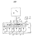
- Figure 2 shows the push out device with the containers on a conveyor of the glassware forming machine.
- The push out device is adapted for use with a multi gob glassware forming machine, as shown, with a triple gob machine. The device is arranged to remove moulded containers B1, B2, B3 from a dead plate 4 of the machine to a
conveyor 6 by which the containers are carried away from the machine for a further operations - e.g. for annealing, inspection and packing. - The push out device comprises a
pusher head 8 which comprises a piston andcylinder arrangement 10 from which extends apiston rod 12 which supports ahead frame 14. - The
frame 14 comprises asupport bar 16, fixed to therod 12, and across bar 18. Threepusher fingers first finger 22 is fixed to thecross bar 18, while the second andthird pusher fingers bar 18. Preferably thebar 18 is of non-circular cross section to maintain thefingers - Mounted on the
cross bar 18 are twoadjustable stops spacer 30. Thestops bar 18, thespacer 30 is slidable on the bar. Secured to one of twoside plates bars cylinder device 34 comprising apiston rod 36. Alug 38 on thepusher finger 24 is attached to an end portion of the rod 36: asupport 40 through which the rod may freely move is secured to thesupport bar 16 and alug 42 secured to thefinger 22 supports asleeve 44 which slides on thepiston rod 36. Aspring 46 extends between thesleeve 44 and the piston andcylinder device 34
In the operation of the push out device, thepusher head 8 is in a retracted position (not shown) when moulded containers B removed from the forming machine are positioned on the dead plate 4 by a take out mechanism of the machine, and is in an orientation in which thehead 8 faces the dead plate. Thepusher head 8 is then extended to bring thepusher fingers conveyor 6, thus to sweep the containers B off the dead plate onto theconveyor 6. Thepusher head 8 is then moved into its retracted position by operative of the piston andcylinder arrangement 10, thus to clear the containers B to be carried off by the conveyor. - The containers B1, B2, B3 when placed on the dead plate 4 are in the same spacing as that of the moulds of the forming machine, Y in Figure 1. As the push out device rotates to sweep the containers from the dead plate onto the conveyor the piston and
cylinder device 34 is operated to draw in thepiston rod 36. This drawing in movement moves thepusher finger 24 on thebar 18 until it contacts thespacer 30, which contacts thepusher finger 22 which is moved until it contacts thestop 26. The containers B3 and B2 in contact with thepusher finger - On the return of the pusher head into its orientation facing the dead plate the
device 34 is operated to move thepiston rod 36 outwardly. This returns thepusher finger 24 to its original position determined by thestop 28, while thespring 46 asserts itself to return thefinger 22 to its original position determined by abutment of thesleeve 44 against thesupport 40. - It will be understood that by simple modifications of the above described push out device, it can be arranged that the spacing between the containers is increased as they are swept off the dead plate onto the conveyor.
Claims (4)
- A push out device adapted for use with a multi gob glassware forming machine to remove moulded containers from a dead plate (4) of the machine to a conveyor (6), comprising at least two pusher fingers (20,22,24) which are mounted for movement between an operative, extended position and a retracted position by means of a pusher head, (8) and rotary means on which the pusher head is mounted and which is arranged to rotate the pusher head from an orientation in which it faces the dead plate to an orientation in which it faces the conveyor, characterized in that the pusher fingers (20,22,24) are mounted for relative movement in the direction of the line of the containers and the device comprising means (34,36) for so moving the pusher fingers between contacting the containers on the dead plate (4) and releasing them on the conveyor (6) that the spacing of the containers on the conveyor (6) is varied from the spacing of the containers on the dead plate (4).
- A push out device according to claim 1 characterized in that the pusher fingers are moved together between contacting the containers on the dead plate and releasing them on the conveyor so that the spacing of the containers on the conveyor is less than that on the dead plate
- A push out device according to claim 2 characterized in that the pusher fingers (20,22,24) are mounted on a cross bar (18), the leading pusher finger (20) being fixed to the cross bar and the other pusher finger(s) (22,24) being slidably mounted on the cross bar (18), the moving means (34,36) being arranged to move the slidably mounted pusher finger(s) between a wider spacing and a closer spacing.
- A push out device according to claim 3 characterized in that it comprises a fixed leading pusher finger (20) and two movable pusher fingers (22,24).
Applications Claiming Priority (2)
| Application Number | Priority Date | Filing Date | Title |
|---|---|---|---|
| GB9007853 | 1990-04-06 | ||
| GB909007853A GB9007853D0 (en) | 1990-04-06 | 1990-04-06 | Push out device |
Publications (2)
| Publication Number | Publication Date |
|---|---|
| EP0457420A1 true EP0457420A1 (en) | 1991-11-21 |
| EP0457420B1 EP0457420B1 (en) | 1993-09-22 |
Family
ID=10674024
Family Applications (1)
| Application Number | Title | Priority Date | Filing Date |
|---|---|---|---|
| EP91302008A Expired - Lifetime EP0457420B1 (en) | 1990-04-06 | 1991-03-11 | Push out device |
Country Status (6)
| Country | Link |
|---|---|
| US (1) | US5056648A (en) |
| EP (1) | EP0457420B1 (en) |
| JP (1) | JPH04223925A (en) |
| AU (1) | AU634362B2 (en) |
| DE (1) | DE69100393T2 (en) |
| GB (1) | GB9007853D0 (en) |
Cited By (8)
| Publication number | Priority date | Publication date | Assignee | Title |
|---|---|---|---|---|
| US6935693B2 (en) | 2002-03-22 | 2005-08-30 | Milsco Manufacturing, A Unit Of Jason Incorporated | Seat suspension |
| DE102004007507A1 (en) * | 2004-02-13 | 2005-09-08 | Ernst Pennekamp Gmbh & Co. Ohg | Mechanical handling system for glass bottles or glass jars has control mechanism for non-linear inputs |
| EP1627859A1 (en) * | 2004-08-18 | 2006-02-22 | BOTTERO S.p.A. | Transfer apparatus for transferring glass articles |
| EP1627858A1 (en) * | 2004-08-18 | 2006-02-22 | BOTTERO S.p.A. | Transfer apparatus for transferring glass articles |
| CN102381557A (en) * | 2010-08-30 | 2012-03-21 | 鸿富锦精密工业(深圳)有限公司 | Device for separating and merging articles |
| DE102012205060A1 (en) * | 2012-03-29 | 2013-10-02 | Robert Bosch Gmbh | Sliding device, transport arrangement and packaging arrangement |
| CN103922118A (en) * | 2014-04-24 | 2014-07-16 | 哈尔滨三联药业股份有限公司 | Bottle arranging mechanism of bottle blowing machine |
| CN105173692A (en) * | 2015-08-21 | 2015-12-23 | 苏州博众精工科技有限公司 | Fixed-distance transferring mechanism |
Families Citing this family (11)
| Publication number | Priority date | Publication date | Assignee | Title |
|---|---|---|---|---|
| GB9023103D0 (en) * | 1990-10-24 | 1990-12-05 | Emhart Ind | Push out device for a glassware forming machine |
| US5061309A (en) * | 1991-02-06 | 1991-10-29 | Emhart Industries, Inc. | Multiple row pusher system for glass forming machine |
| JP3546217B2 (en) * | 1997-11-21 | 2004-07-21 | 株式会社ダイフク | Article transfer equipment |
| DE29902149U1 (en) | 1999-02-06 | 1999-08-05 | Fa. Hermann Heye, 31683 Obernkirchen | Device for pushing hollow glass objects onto a conveyor belt |
| DE19957079B4 (en) | 1999-11-26 | 2004-03-11 | Heye International Gmbh | Device for pushing glass objects |
| DE102004023473B4 (en) * | 2004-05-12 | 2006-05-24 | Multivac Sepp Haggenmüller Gmbh & Co. Kg | Packaging machine and method for feeding containers in a packaging machine |
| US8250955B2 (en) * | 2007-10-22 | 2012-08-28 | Formax, Inc. | Food article transfer mechanism for a food article slicing machine |
| CN103723490B (en) * | 2013-12-31 | 2015-09-09 | 吴江区铜罗新世纪包装厂 | A kind of for carrying the conveying mechanism of the steel wire after putting on and handle |
| CN205892038U (en) * | 2015-12-28 | 2017-01-18 | 深圳市步先包装机械有限公司 | Divide bucket mechanism and cask flushing device |
| CN109399186B (en) * | 2018-12-29 | 2024-02-06 | 都江堰宁江宗汇精密小型蜗杆有限责任公司 | Automatic discharging mechanism for worm blank |
| US20230125230A1 (en) * | 2021-10-25 | 2023-04-27 | Provisur Technologies, Inc. | Pivoting loading tray assembly for food product slicing apparatus and method of use |
Citations (2)
| Publication number | Priority date | Publication date | Assignee | Title |
|---|---|---|---|---|
| GB1355271A (en) * | 1971-10-13 | 1974-06-05 | Maul Bros Inc | Glass container handling apparatus |
| US4771878A (en) * | 1983-08-12 | 1988-09-20 | Emhart Industries, Inc. | Pusher cylinder |
Family Cites Families (9)
| Publication number | Priority date | Publication date | Assignee | Title |
|---|---|---|---|---|
| US3249201A (en) * | 1964-11-24 | 1966-05-03 | Emhart Corp | Apparatus for moving newly formed glassware articles of unstable configuration onto a conveyor |
| US3318433A (en) * | 1965-11-05 | 1967-05-09 | Emhart Corp | Apparatus for moving glass containers onto a moving conveyor |
| US3400802A (en) * | 1966-12-29 | 1968-09-10 | Emhart Corp | Apparatus for moving newly formed glassware articles onto a continuously moving conveyor |
| US3595365A (en) * | 1970-03-18 | 1971-07-27 | C S S Machine & Tool Co | Gear drive for 90 degree push-out for glassware forming apparatus |
| US3679041A (en) * | 1971-01-06 | 1972-07-25 | Dart Ind Inc | Apparatus for the transfer of articles |
| US3764284A (en) * | 1971-12-20 | 1973-10-09 | Emhart Corp | Method and apparatus for treating newly formed ware |
| DE2746675C2 (en) * | 1977-10-18 | 1979-10-04 | Hermann Heye, 3063 Obernkirchen | Glass forming machine with several stations |
| US4340413A (en) * | 1980-09-27 | 1982-07-20 | E. R. Lattimer Limited | Transfer mechanism in a glassware forming machine |
| US4462519A (en) * | 1982-08-03 | 1984-07-31 | Maul Technology Corporation | Glass container pusher |
-
1990
- 1990-04-06 GB GB909007853A patent/GB9007853D0/en active Pending
-
1991
- 1991-03-11 DE DE91302008T patent/DE69100393T2/en not_active Expired - Fee Related
- 1991-03-11 EP EP91302008A patent/EP0457420B1/en not_active Expired - Lifetime
- 1991-03-26 US US07/675,308 patent/US5056648A/en not_active Expired - Fee Related
- 1991-04-04 AU AU74110/91A patent/AU634362B2/en not_active Ceased
- 1991-04-05 JP JP3073103A patent/JPH04223925A/en active Pending
Patent Citations (2)
| Publication number | Priority date | Publication date | Assignee | Title |
|---|---|---|---|---|
| GB1355271A (en) * | 1971-10-13 | 1974-06-05 | Maul Bros Inc | Glass container handling apparatus |
| US4771878A (en) * | 1983-08-12 | 1988-09-20 | Emhart Industries, Inc. | Pusher cylinder |
Cited By (12)
| Publication number | Priority date | Publication date | Assignee | Title |
|---|---|---|---|---|
| US6935693B2 (en) | 2002-03-22 | 2005-08-30 | Milsco Manufacturing, A Unit Of Jason Incorporated | Seat suspension |
| DE102004007507A1 (en) * | 2004-02-13 | 2005-09-08 | Ernst Pennekamp Gmbh & Co. Ohg | Mechanical handling system for glass bottles or glass jars has control mechanism for non-linear inputs |
| DE102004007507B4 (en) * | 2004-02-13 | 2008-01-24 | Ernst Pennekamp Gmbh & Co. Ohg | Device for moving glassware |
| EP1627859A1 (en) * | 2004-08-18 | 2006-02-22 | BOTTERO S.p.A. | Transfer apparatus for transferring glass articles |
| EP1627858A1 (en) * | 2004-08-18 | 2006-02-22 | BOTTERO S.p.A. | Transfer apparatus for transferring glass articles |
| US7325668B2 (en) | 2004-08-18 | 2008-02-05 | Bottero S.P.A. | Transfer unit for transferring glass articles |
| CN102381557A (en) * | 2010-08-30 | 2012-03-21 | 鸿富锦精密工业(深圳)有限公司 | Device for separating and merging articles |
| CN102381557B (en) * | 2010-08-30 | 2013-08-28 | 鸿富锦精密工业(深圳)有限公司 | Device for separating and merging articles |
| DE102012205060A1 (en) * | 2012-03-29 | 2013-10-02 | Robert Bosch Gmbh | Sliding device, transport arrangement and packaging arrangement |
| CN103922118A (en) * | 2014-04-24 | 2014-07-16 | 哈尔滨三联药业股份有限公司 | Bottle arranging mechanism of bottle blowing machine |
| CN103922118B (en) * | 2014-04-24 | 2016-02-17 | 哈尔滨三联药业股份有限公司 | The bottle body of bottle blowing machine |
| CN105173692A (en) * | 2015-08-21 | 2015-12-23 | 苏州博众精工科技有限公司 | Fixed-distance transferring mechanism |
Also Published As
| Publication number | Publication date |
|---|---|
| DE69100393T2 (en) | 1994-03-03 |
| JPH04223925A (en) | 1992-08-13 |
| US5056648A (en) | 1991-10-15 |
| AU634362B2 (en) | 1993-02-18 |
| AU7411091A (en) | 1991-10-10 |
| DE69100393D1 (en) | 1993-10-28 |
| EP0457420B1 (en) | 1993-09-22 |
| GB9007853D0 (en) | 1990-06-06 |
Similar Documents
| Publication | Publication Date | Title |
|---|---|---|
| EP0457420B1 (en) | Push out device | |
| CN110546111B (en) | Takeout mechanism of machine for forming glass articles | |
| US6993935B2 (en) | Method for blowing and removing glass containers | |
| AU611347B2 (en) | Dual injection mold preform transfer assembly | |
| US4636241A (en) | Take-out mechanism for removing containers from a mould of a glassware forming machine | |
| US6722488B2 (en) | Method and apparatus for transferring articles in unison | |
| US4162911A (en) | Plural glass forming machines with lehr conveyor | |
| US3043447A (en) | Article take-out mechanism | |
| US3549191A (en) | Take-out mechanism for glassware forming machine | |
| EP0694505A2 (en) | Method and apparatus for forming wide mouth glassware | |
| US3759686A (en) | Neck ring arms for glassware forming machine | |
| EP0455331A1 (en) | Take out device | |
| EP0693042A1 (en) | Mold clamping mechanism for glass container forming machine | |
| US3528796A (en) | Mold locking mechanism for glassware forming machine | |
| US2925183A (en) | Pneumatic take-out apparatus for glassware | |
| US4062668A (en) | Apparatus for arc movement of the parison | |
| EP0136046A1 (en) | Take-out mechanism for a glassware forming machine | |
| EP0554620B1 (en) | Takeout device | |
| US4276076A (en) | Transfer means of glassware forming machines | |
| US3223511A (en) | Glassware forming machine | |
| JPH06305737A (en) | Parison carrying mechanism | |
| US2474708A (en) | Apparatus for forming glass articles | |
| EP0148574A1 (en) | Removing containers from a mould of a glassware forming machine | |
| CS203838B1 (en) | Device for transporting glass semiproducts from conveyer into vertical lathe | |
| EP0771312A1 (en) | Formation of glass articles |
Legal Events
| Date | Code | Title | Description |
|---|---|---|---|
| PUAI | Public reference made under article 153(3) epc to a published international application that has entered the european phase |
Free format text: ORIGINAL CODE: 0009012 |
|
| AK | Designated contracting states |
Kind code of ref document: A1 Designated state(s): DE FR GB IT |
|
| 17P | Request for examination filed |
Effective date: 19911203 |
|
| 17Q | First examination report despatched |
Effective date: 19921127 |
|
| RAP1 | Party data changed (applicant data changed or rights of an application transferred) |
Owner name: EMHART GLASS MACHINERY INVESTMENTS INC. |
|
| GRAA | (expected) grant |
Free format text: ORIGINAL CODE: 0009210 |
|
| AK | Designated contracting states |
Kind code of ref document: B1 Designated state(s): DE FR GB IT |
|
| REF | Corresponds to: |
Ref document number: 69100393 Country of ref document: DE Date of ref document: 19931028 |
|
| ET | Fr: translation filed | ||
| ITF | It: translation for a ep patent filed | ||
| PLBE | No opposition filed within time limit |
Free format text: ORIGINAL CODE: 0009261 |
|
| STAA | Information on the status of an ep patent application or granted ep patent |
Free format text: STATUS: NO OPPOSITION FILED WITHIN TIME LIMIT |
|
| 26N | No opposition filed | ||
| PGFP | Annual fee paid to national office [announced via postgrant information from national office to epo] |
Ref country code: GB Payment date: 19980219 Year of fee payment: 8 |
|
| PGFP | Annual fee paid to national office [announced via postgrant information from national office to epo] |
Ref country code: FR Payment date: 19980221 Year of fee payment: 8 |
|
| PGFP | Annual fee paid to national office [announced via postgrant information from national office to epo] |
Ref country code: DE Payment date: 19980223 Year of fee payment: 8 |
|
| PG25 | Lapsed in a contracting state [announced via postgrant information from national office to epo] |
Ref country code: GB Free format text: LAPSE BECAUSE OF NON-PAYMENT OF DUE FEES Effective date: 19990311 |
|
| GBPC | Gb: european patent ceased through non-payment of renewal fee |
Effective date: 19990311 |
|
| PG25 | Lapsed in a contracting state [announced via postgrant information from national office to epo] |
Ref country code: FR Free format text: LAPSE BECAUSE OF NON-PAYMENT OF DUE FEES Effective date: 19991130 |
|
| REG | Reference to a national code |
Ref country code: FR Ref legal event code: ST |
|
| PG25 | Lapsed in a contracting state [announced via postgrant information from national office to epo] |
Ref country code: DE Free format text: LAPSE BECAUSE OF NON-PAYMENT OF DUE FEES Effective date: 20000101 |
|
| PG25 | Lapsed in a contracting state [announced via postgrant information from national office to epo] |
Ref country code: IT Free format text: LAPSE BECAUSE OF NON-PAYMENT OF DUE FEES;WARNING: LAPSES OF ITALIAN PATENTS WITH EFFECTIVE DATE BEFORE 2007 MAY HAVE OCCURRED AT ANY TIME BEFORE 2007. THE CORRECT EFFECTIVE DATE MAY BE DIFFERENT FROM THE ONE RECORDED. Effective date: 20050311 |