EP0457383A2 - Spark plug ignition system - Google Patents
Spark plug ignition system Download PDFInfo
- Publication number
- EP0457383A2 EP0457383A2 EP91200968A EP91200968A EP0457383A2 EP 0457383 A2 EP0457383 A2 EP 0457383A2 EP 91200968 A EP91200968 A EP 91200968A EP 91200968 A EP91200968 A EP 91200968A EP 0457383 A2 EP0457383 A2 EP 0457383A2
- Authority
- EP
- European Patent Office
- Prior art keywords
- current
- ignition system
- arc
- primary winding
- spark plug
- Prior art date
- Legal status (The legal status is an assumption and is not a legal conclusion. Google has not performed a legal analysis and makes no representation as to the accuracy of the status listed.)
- Granted
Links
Images


Classifications
-
- F—MECHANICAL ENGINEERING; LIGHTING; HEATING; WEAPONS; BLASTING
- F02—COMBUSTION ENGINES; HOT-GAS OR COMBUSTION-PRODUCT ENGINE PLANTS
- F02P—IGNITION, OTHER THAN COMPRESSION IGNITION, FOR INTERNAL-COMBUSTION ENGINES; TESTING OF IGNITION TIMING IN COMPRESSION-IGNITION ENGINES
- F02P3/00—Other installations
- F02P3/02—Other installations having inductive energy storage, e.g. arrangements of induction coils
- F02P3/04—Layout of circuits
- F02P3/045—Layout of circuits for control of the dwell or anti dwell time
- F02P3/0453—Opening or closing the primary coil circuit with semiconductor devices
- F02P3/0456—Opening or closing the primary coil circuit with semiconductor devices using digital techniques
-
- F—MECHANICAL ENGINEERING; LIGHTING; HEATING; WEAPONS; BLASTING
- F02—COMBUSTION ENGINES; HOT-GAS OR COMBUSTION-PRODUCT ENGINE PLANTS
- F02P—IGNITION, OTHER THAN COMPRESSION IGNITION, FOR INTERNAL-COMBUSTION ENGINES; TESTING OF IGNITION TIMING IN COMPRESSION-IGNITION ENGINES
- F02P15/00—Electric spark ignition having characteristics not provided for in, or of interest apart from, groups F02P1/00 - F02P13/00 and combined with layout of ignition circuits
- F02P15/10—Electric spark ignition having characteristics not provided for in, or of interest apart from, groups F02P1/00 - F02P13/00 and combined with layout of ignition circuits having continuous electric sparks
-
- F—MECHANICAL ENGINEERING; LIGHTING; HEATING; WEAPONS; BLASTING
- F02—COMBUSTION ENGINES; HOT-GAS OR COMBUSTION-PRODUCT ENGINE PLANTS
- F02P—IGNITION, OTHER THAN COMPRESSION IGNITION, FOR INTERNAL-COMBUSTION ENGINES; TESTING OF IGNITION TIMING IN COMPRESSION-IGNITION ENGINES
- F02P3/00—Other installations
- F02P3/005—Other installations having inductive-capacitance energy storage
-
- F—MECHANICAL ENGINEERING; LIGHTING; HEATING; WEAPONS; BLASTING
- F02—COMBUSTION ENGINES; HOT-GAS OR COMBUSTION-PRODUCT ENGINE PLANTS
- F02P—IGNITION, OTHER THAN COMPRESSION IGNITION, FOR INTERNAL-COMBUSTION ENGINES; TESTING OF IGNITION TIMING IN COMPRESSION-IGNITION ENGINES
- F02P3/00—Other installations
- F02P3/01—Electric spark ignition installations without subsequent energy storage, i.e. energy supplied by an electrical oscillator
-
- F—MECHANICAL ENGINEERING; LIGHTING; HEATING; WEAPONS; BLASTING
- F02—COMBUSTION ENGINES; HOT-GAS OR COMBUSTION-PRODUCT ENGINE PLANTS
- F02P—IGNITION, OTHER THAN COMPRESSION IGNITION, FOR INTERNAL-COMBUSTION ENGINES; TESTING OF IGNITION TIMING IN COMPRESSION-IGNITION ENGINES
- F02P9/00—Electric spark ignition control, not otherwise provided for
- F02P9/002—Control of spark intensity, intensifying, lengthening, suppression
Definitions
- This invention relates to an ignition system for igniting a spark plug of an internal combustion engine and more particularly to an ignition system which can develop an alternating current which is applied to the spark plug of the engine.
- One of the objects of this invention is to provide an ignition system which can deliver alternating current to the spark plug for a length of time after initiation of the spark plug arc.
- Another object of this invention is to provide an alternating current ignition system where the magnitude of arc current can be controlled as well as the duration of the arc.
- an ignition system for igniting a spark plug of an internal combustion engine as defined in claim 1.
- the ignition system utililizes a transformer that has a centre tapped primary winding and a secondary winding which is connected to the spark plug.
- This embodiment has a capacitor which is charged by a capacitor charging circuit powered from a low voltage direct voltage source, such as the 12 volt battery of the motor vehicle.
- the charging circuit is a controlled current source and includes an inductor.
- the capacitor is discharged through one-half of the primary winding and thereafter the battery supplies current to the primary windings in opposite directions through a pair of switches to cause an alternating current to be applied to the spark plug to maintain the arc initiated by discharge of the capacitor.
- the embodiment separates the two basic tasks of an ignition system, namely, the initiation of the arc and the delivery of energy to maintain the established arc.
- the transformer instead of having a centre-tapped primary winding, has a single primary winding.
- the capacitor is discharged through the single primary winding and the secondary winding develops a voltage high enough to initiate a spark plug arc. Thereafter, the single primary winding is energized by a full bridge inverter powered by the battery to maintain the spark plug arc.
- the ignition system can be arranged such that it does not use a capacitor but rather uses the inductor of the controlled current source to initiate the spark plug arc.
- the inductive system does not perform as well as the embodiment which uses the capacitor when firing fouled spark plugs or where the engine is supplied with methanol fuels.
- the embodiment that uses the discharge of a capacitor to initiate the spark plug arc is, accordingly, the preferred embodiment.
- plug erosion with the system of this invention is expected to be less than a multi-strike system.
- FIG. 1 a generalized circuit diagram is illustrated of an embodiment of alternating current ignition system which utilizes the discharge of a capacitor to initiate a spark plug arc.
- the circuit of Figure 3 shows specific components of the circuit of Figure 1.
- the ignition system of Figure 1 supplies a spark firing voltage to a spark plug 10 associated with the cylinder of a spark ignited internal combustion engine.
- the spark plug 10 which has a capacitance denoted as CSP, is supplied with a spark firing voltage VS by the secondary winding 12 of a transformer 14; specifically, opposite ends of the secondary winding are connected respectively to the electrodes of the spark plug 10.
- the transformer has a centre-tapped primary winding 16 comprising primary winding portions 16A and 16B which have an equal number of turns.
- the turns ratio N between a winding portion, for example, winding portion 16A and secondary winding 12 is preferably about 100 (that is, there are preferably about 100 turns on secondary winding 12 for each turn of primary winding portion 16A).
- the centre tap 18 of the primary winding is connected to a conductor 20.
- One side of winding portion 16A is connected to one side of switch S1 through line 22.
- the opposite side of switch S1 is connected to conductor 24.
- one side of primary winding portion 16B is connected to one side of switch S2 through line 25 and the opposite side of switch S2 is connected to conductor 24.
- the transformer 14 and switches S1 and S2 form a current source DC-to-AC inverter which has been designated as 26.
- Lines 20 and 24 form the input to the inventer and are connected to a circuit 28 which functions as a controlled current source and a capacitor charging circuit.
- Circuit 28 comprises a direct voltage source 29, shown as a battery and which may be the 12 volt storage battery of a motor vehicle.
- the positive terminal of voltage source 29 is connected to one side of switch S3 and its negative terminal is connected to conductor 24.
- a capacitor C which may have a capacitance of about 0.1 microfarad is connected between node X on line 20 and line 24.
- a small inductor 31 of about 0.5mH is connected between nodes Y and X.
- a diode D is connected between node Y and line 24.
- the circuit of Figure 1 has a constant current controller 30 which controls the opening and closing of switch S3 and which senses the current IL through inductor 31 by means of current sensing resistor 32.
- the inductor current IL is compared to reference currents IH or IM provided respectively by circuits 34 and 35, as is described in further detail below.
- the circuit further comprises an inverter control circuit 36 which controls the on-off switching of switches S1 and S2.
- the circuit 28 and the controller 30 operate as a constant-off, time pulse-width-modulation (PWM) type current controller adapted to maintain the inductor current IL approximately constant.
- PWM time pulse-width-modulation
- the capacitor C is charged to a high voltage level of about 400 volts and is used to initiate the spark.
- Switches S1 and S2 alternately switch the inductor current IL between the two primary windings 16A and 16B of the centre-tapped transformer 14 to produce an alternating spark current in the secondary winding 12.
- the circuit of Figure 1 separates the two basic tasks of the ignition system, namely, to initiate the spark plug arc and to deliver energy to the established arc.
- the capacitor C stores just enough energy to initiate an arc and once the arc is established, it plays no further part in the circuit operation.
- the arc is maintained for any length of time by continuously passing an alternating current to spark plug 10.
- the energy delivered to the arc comes directly from the battery 29 without any intermediate storage stage.
- the direction of the two primary currents IP1 and IP2 is such that the magnetic flux produced by one half of the primary winding 16 cancels the flux produced by the other half, and there is no net change of flux associated with the primary winding 16. This causes the voltage VP1 across primary winding portion 16A and the voltage VP2 across primary winding portion 16B to be equal to zero and therefore, the voltage across the entire primary winding 16, i.e. the voltage between lines 22 and 25, is also to be zero.
- the capacitor voltage VC (which is equal to voltage at node X) is also equal to zero.
- the inductor current IL rises with a slope of VB/L where VB is the voltage of source 29 and L is the inductance of inductor 31. Some time before time T1, the inductor current IL equals the reference value IH. Thereafter, the current controller 30 turns the switch S3 on or off, as needed, so that the inductor current IL remains between IH and (IH- ⁇ I). The operation of the current controller will be described in more detail later.
- the switches S1 and S2 are turned off. Since the magnetic flux in the inductor 31 can not change instantaneously, the inductor 31 produces a voltage burst retarding the drop in current IL as is well known, which charges the capacitor C and thereby causes the inductor 31 to transfer some of its stored energy to the capacitor C. As a result, the capacitor voltage VC at node X increases.
- the capacitor voltage VC is equal to VH (in practice about 400 V) and the switch S1 is turned on to connect the capacitor C across the primary winding portion 16A.
- the secondary voltage VS of secondary winding 12 rises extremely fast to a very large value as a result of the large turns ratio N of the transformer 14 and by time T3 an arc is established at spark plug 10.
- the arc at spark plug 10 starts when the voltage VS exceeds the breakdown voltage of the spark plug which may be about 25 KV. During the very short period between times T2 and T3, the capacitor voltage VC drops rapidly and the primary and secondary currents are of a pulsed nature.
- the voltage VSP is lower than the break down voltage of the spark plug and is a voltage that will maintain the spark plug arc, once the arc has been initiated by the higher secondary voltage VS caused by the discharge of capacitor C on the primary side. In practice, the voltage VSP may be about 800 volts.
- the switch S1 When the switch S1 is on, i.e. when the secondary voltage is VSP, the voltage VX at node X is equal to VSP/N. Similarly, when the switch S2 is on, i.e. when the secondary voltage is -VSP, the voltage VX is also VSP/N.
- switch S1 is turned on again and S2 is turned off to establish a positive polarity arc current. This process is continued to produce an alternating spark current for any desired length of time. To terminate the arc, the battery supply is cutoff by turning the switch S3 off.
- the switch S3 is turned on and off, as needed, to maintain an approximately constant inductor current through inductor 31, equal to the reference currents IH or IM as the case may be.
- a reference circuit IH is used to charge the capacitor C while a reference current level IM is used to maintain the arc.
- the switch S3 is turned on.
- the voltage across the inductor L is (VB-VX) and the current starts increasing with a slope of (VB-VX)/L.
- the switch S3 is turned off for a fixed duration TOFF.
- the diode D turns on and the current IL flows through the diode D.
- the voltage across the inductor L is (-VX) and the current IL starts reducing at a rate of VX/L for a fixed duration of TOFF. Therefore, the drop in the inductor current ⁇ I is equal to (TOFF)*(VX)/L.
- This method of obtaining a controlled current source is called constant off-time, pulse width modulation. It can be appreciated that an average current IO is developed.
- the arc at spark plug 10 represents an electrical load which consumes the electrical power to produce heat.
- the circuit continuously supplies the arc with an alternating current by switching the DC inductor current IL through the primary winding portions 16A and 16B using the switches S1 and S2.
- the inductor current is maintained at the average level IO by connecting the battery to the input side of the inductor L through the switch S3, as needed. While the arc is maintained, there is a continuous energy flow from the battery to the arc without any intermediate energy storage stage. Thus, while the arc is being maintained, there is a balance between the average power drawn from the battery and the power delivered to the arc.
- FIG. 3 an ignition circuit is shown that performs the same functions as the circuit of Figure 1.
- Figure 3 the same reference numerals have been used as were used in Figure 1 to identify corresponding circuit elements.
- Figure 3 illustrates specific circuit components of an embodiment which performs the functions of the system shown in Figure 1.
- switches S2 and S1 take the form of n-type insulated gate bipolar transistors 42 and 44 (which may be type IXGH 20N100A transistors from the IXYS Corp).
- Diodes D1 and D2 are respectively connected across transistors 44 and 42, each having its anode connected to the emitter of its respective transistor and its cathode connected to the collector of its respective transistor. These diodes are provided to protect transistors 44 and 42 from reverse current caused by leakage inductance and magnetizing inductance of transformer 14.
- Switch S3 is provided by a metal oxide field-effect transistor 46 (which may be a type SMP50N06 Silconix Inc.).
- the sensing of the inductor current is accomplished by means of a small resistor 48 connected in series with the battery 29 and the inductor 31.
- the voltage across resistor 48 is a function of inductor current IL.
- the spark plug 10 is connected to secondary winding 12 through a 1K ohm resistor 50 which serves as an EMI suppressor.
- the bases of transistors 42 and 44 are connected to a gate driver circuit (which may be a Teledyne type TSC427 gate driver). Circuit 52 biases transistors 42 and 44 on and off in response to input signals, as is described below.
- the on/off signals for transistors 42 and 44 are generated by a look-up table by using an EPROM (Erasable Programmable Read Only Memory) 54 and counters 56 and 58.
- the EPROM 54 may be a type 27128 EPROM from the Intel Corporation and counters 56 and 58 may each be RCA CD4040, 12 bit counters.
- Outputs Q2 and Q1 of EPROM 54 are connected to driver 52. Output Q3 is connected to a line 60.
- Counter 56 is connected to a square wave oscillator or clock pulse source 62 which has a frequency of 1 MHz. The pulse train developed by oscillator 62 is used as a timing clock.
- the two cascaded counters 56 and 58 form a 14-bit counter and count the clock pulses from source 62.
- the Q1 to Q12 outputs of counter 56 are connected respectively to the A0 to A11 inputs of EPROM 54.
- the Q1 and Q2 outputs of counter 58 are connected respectively to the A12 and A13 inputs of EPROM 54.
- the EPROM's address increments and a set of outputs appear at the outputs Q1, Q2 and Q3 of the EPROM.
- the outputs Q1 and Q2 control on or off conditions of the transistors 42 and 44 respectively.
- the output Q3, which is applied to line 60, controls the SPDT (Single Pole Double Throw) analog switch 64 (which may be an RCA type CD4053 analog switch).
- the counter increments every 1 ⁇ s, and accordingly every increment in the EPROM's address is a 1 ⁇ s increment in time.
- the circuit of Figure 3 has a constant off time, pulse width modulated controller 66 (which may be a Unitrode UC3846 controller). It comprises an amplifier 66A, a comparator 66B and a monostable multivibrator 66C.
- the multivibrator 66C has an off-time of 5 microseconds in duration, and has its output connected to a high side gate driver 68 (which may be an International Rectifier type IR2110 gate driver).
- Driver 68 is connected to the gate of field effect transistor 46.
- the fixed off-time pulse width modulated control of the inductor current is achieved by using MOSFET 46 as the switch S3 together with the pulse width modulation controller 66.
- the inductor current IL (IL is same as the MOSFET current when it is on) is measured as a voltage drop across resistor 48. This voltage, representing the inductor current IL, is amplified and compared with a voltage representing a reference current.
- High side gate driver 68 provides the necessary gate voltage required to turn on the MOSFET 46.
- Two reference signals, IH and IM are generated by a resistive potential divider R1 and R2 connected across 5 volt voltage source.
- the reference current level IM can be changed by adjusting the variable resistor R2.
- the analog switch 64 selects one of the two reference signals IM or IH under the control of a signal on line 60 from EPROM 54.
- the system of Figure 3 has a crankshaft position sensor 70 which is driven by the crankshaft 72 of an engine 74.
- the sensor 70 develops a signal when the piston of the engine is in a predetermined position at which the spark plug 10 should be fired.
- the output of sensor 70 is connected to a variable pulse-width monostable multivibrator 76.
- the pulse-width can be adjusted by varying variable resistor R3.
- the output of multivibrator 76 is connected to lines 78 and 80.
- This output is a square-wave 82 which has been labelled "spark duration" since the pulse-width of this square-wave corresponds to the time period that an arc is maintained across spark plug 10.
- the square-wave 82 is initiated when monostable 76 receives a timing signal from sensor 70.
- the square-wave 82 enables controller 66 and counters 56 and 58.
- the transistors 42 and 44 are turned on and the inductor current equal to IH is demanded from the pulse width modulation controller 66. Since the inductor current was previously zero, the pulse width modulation controller 66 turns the MOSFET 46 on. This condition is maintained for 1000 ⁇ s (1 ms) allowing sufficient time for the inductor current to rise from 0 to IH. In case the inductor current reaches the reference level IH early, the pulse width modulation current controller 66 keeps the inductor current within ⁇ I of IH by turning the MOSFET 46 on and off as needed.
- the transistors 42 and 44 are turned off for 4 ⁇ s so that the inductor current can charge the capacitor C.
- the transistor 44 is turned on to discharge the capacitor through primary winding 16A to initiate the arc.
- the transistor 44 remains on for the next 25 ⁇ s to drive a positive half cycle of the arc current.
- the reference current fed to the pulse width modulation controller 66 is then changed from IH to IM by the change of signal on line 60 from Q3.
- transistor 44 is turned off and transistor 42 is turned on for the next 25 ⁇ s duration to provide the negative half cycle of the arc current.
- variable pulse width monostable pulse 82 terminates.
- the pulse width mnodulation controller 66 and the counters 56 and 58 are disabled, the two transistors 42 and 44 and the MOSFET 46 are turned off and the arc is terminated.
- Figure 4 shows a modified alternating current ignition circuit that differs from the embodiments of Figures 1 and 3 in that the capacitor C is not used and the timing sequence of the switches S1 and S2 is modified. Further, the embodiment of Figure 4 uses only one reference current namely reference current IM. The arc is initiated by energy stored in inductor 31 and it is maintained for a predetermined duration by passing an alternating current to spark plug 10.
- the current IL is forced through the primary winding portion 16A, which results in a secondary current IS equal to IL/N.
- This secondary current starts charging the spark plug capacitance CSP and the secondary voltage VS starts to increase very rapidly and at time T2, it equals the break down voltage of the spark plug and an arc is established across spark plug 10. Now, the secondary current IS starts flowing through the arc and the secondary voltage falls to VSP.
- the switch S1 is turned off and simultaneously the switch S2 is turned on so that the secondary (arc) current reverses its polarity and the secondary voltage becomes -VSP.
- switch S1 is turned on again and S2 is turned off to establish a positive polarity arc current. This process is continually repeated to produce an alternating spark current for any desired length of time.
- the battery supply is cutoff by turning the switch S3 off.
- This circuit of Figure 4 differs from the circuits of Figures 1 and 3 in the way an arc is established. Once the arc is established, the circuit operation and the energy and power relationships are identical to the circuit of Figures 1 and 3.
- the circuit of Figure 4 can be implemented in a manner shown in Figure 3 by eliminating the capacitor C the current reference IH and appropriate change in the data stored in the EPROM to modify the switching sequence of S1 and S2.
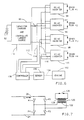
- Figure 6 illustrates an embodiment for use with a multi-cylinder engine and specifically a four cylinder engine.
- reference numeral 90 designates a capacitor charger and controlled current source powered by battery 92.
- Circuit 90 is of the type shown in Figures 1, 3 or 4.
- Circuit 90 feeds four DC to AC inverters, 94, 96, 98 and 100 which are respectively connected to a spark plug.
- Each inverter is of the type shown in Figures 1 or 3.
- an engine 102 has a crankshaft 104 connected to a crankshaft position sensor 106.
- This sensor supplies electrical signals to an electronic controller 108.
- Controller 108 supplies a signal to line 110 which controls circuit 90 in the same manner as the output signal of sensor 70 in Figure 3.
- Controller 108 also develops sequential control signals on lines 112, 114, 116 and 118 for sequentially enabling the inverters 94, 96, 98 and 100 at predetermined crankshaft positions.
- the signals on lines 112-118 are cylinder selector signals for selecting the proper cylinder to be fired. This is a so-called distributorless system.
Abstract
Alternatively, the energy stored in an inductor (31) can be supplied to a primary winding portion (16A, 16B) to initiate an arc. The ignition system is powered by a controlled current source (28) that receives input power from a source of direct voltage (29) such as a battery on a motor vehicle.
Description
- This invention relates to an ignition system for igniting a spark plug of an internal combustion engine and more particularly to an ignition system which can develop an alternating current which is applied to the spark plug of the engine.
- One of the objects of this invention is to provide an ignition system which can deliver alternating current to the spark plug for a length of time after initiation of the spark plug arc.
- Another object of this invention is to provide an alternating current ignition system where the magnitude of arc current can be controlled as well as the duration of the arc.
- According to an aspect of the present invention, there is provided an ignition system for igniting a spark plug of an internal combustion engine as defined in
claim 1. - In an embodiment, the ignition system utililizes a transformer that has a centre tapped primary winding and a secondary winding which is connected to the spark plug. This embodiment has a capacitor which is charged by a capacitor charging circuit powered from a low voltage direct voltage source, such as the 12 volt battery of the motor vehicle. The charging circuit is a controlled current source and includes an inductor. To initiate an arc at the spark plug, the capacitor is discharged through one-half of the primary winding and thereafter the battery supplies current to the primary windings in opposite directions through a pair of switches to cause an alternating current to be applied to the spark plug to maintain the arc initiated by discharge of the capacitor. The embodiment separates the two basic tasks of an ignition system, namely, the initiation of the arc and the delivery of energy to maintain the established arc.
- In another embodiment, the transformer, instead of having a centre-tapped primary winding, has a single primary winding. The capacitor is discharged through the single primary winding and the secondary winding develops a voltage high enough to initiate a spark plug arc. Thereafter, the single primary winding is energized by a full bridge inverter powered by the battery to maintain the spark plug arc.
- In an alternative embodiment, the ignition system can be arranged such that it does not use a capacitor but rather uses the inductor of the controlled current source to initiate the spark plug arc. The inductive system does not perform as well as the embodiment which uses the capacitor when firing fouled spark plugs or where the engine is supplied with methanol fuels. The embodiment that uses the discharge of a capacitor to initiate the spark plug arc is, accordingly, the preferred embodiment.
- Thus, plug erosion with the system of this invention is expected to be less than a multi-strike system.
- An embodiment of the present invention is described below, by way of illustration only, with reference to the accompanying drawings in which:
- Figure 1 is a circuit diagram of an embodiment of alternating current ignition system which utilizes a capacitor for spark plug arc initiation;
- Figure 2 illustrates waveforms related to the operation of the circuit shown in Figure 1;
- Figure 3 is a circuit diagram illustrating in greater detail the circuit components of the embodiment of ignition system shown in Figure 1;
- Figure 4 is a circuit diagram of another embodiment of alternating current ignition system which utilizes an inductor for spark plug arc initiation;
- Figure 5 illustrates waveforms related to the operation of the circuit shown in Figure 4;
- Figure 6 is an embodiment of ignition system for use with a multi-cylinder internal combustion engine;
- Figure 7 shows a full bridge inverter which could be utilized in the embodiment of ignition system of Figures 1, 4 or 6.
- Referring now to Figure 1, a generalized circuit diagram is illustrated of an embodiment of alternating current ignition system which utilizes the discharge of a capacitor to initiate a spark plug arc. The circuit of Figure 3 shows specific components of the circuit of Figure 1.
- The ignition system of Figure 1 supplies a spark firing voltage to a
spark plug 10 associated with the cylinder of a spark ignited internal combustion engine. Thespark plug 10, which has a capacitance denoted as CSP, is supplied with a spark firing voltage VS by thesecondary winding 12 of atransformer 14; specifically, opposite ends of the secondary winding are connected respectively to the electrodes of thespark plug 10. The transformer has a centre-tappedprimary winding 16 comprisingprimary winding portions portion 16A andsecondary winding 12 is preferably about 100 (that is, there are preferably about 100 turns onsecondary winding 12 for each turn ofprimary winding portion 16A). - The
centre tap 18 of the primary winding is connected to aconductor 20. One side of windingportion 16A is connected to one side of switch S1 throughline 22. The opposite side of switch S1 is connected toconductor 24. In a similar fashion, one side ofprimary winding portion 16B is connected to one side of switch S2 throughline 25 and the opposite side of switch S2 is connected toconductor 24. Thetransformer 14 and switches S1 and S2 form a current source DC-to-AC inverter which has been designated as 26.Lines circuit 28 which functions as a controlled current source and a capacitor charging circuit. -
Circuit 28 comprises adirect voltage source 29, shown as a battery and which may be the 12 volt storage battery of a motor vehicle. The positive terminal ofvoltage source 29 is connected to one side of switch S3 and its negative terminal is connected toconductor 24. A capacitor C, which may have a capacitance of about 0.1 microfarad is connected between node X online 20 andline 24. Asmall inductor 31 of about 0.5mH is connected between nodes Y and X. A diode D is connected between node Y andline 24. - The circuit of Figure 1 has a constant
current controller 30 which controls the opening and closing of switch S3 and which senses the current IL throughinductor 31 by means ofcurrent sensing resistor 32. The inductor current IL is compared to reference currents IH or IM provided respectively bycircuits - The circuit further comprises an
inverter control circuit 36 which controls the on-off switching of switches S1 and S2. - The
circuit 28 and thecontroller 30 operate as a constant-off, time pulse-width-modulation (PWM) type current controller adapted to maintain the inductor current IL approximately constant. The capacitor C is charged to a high voltage level of about 400 volts and is used to initiate the spark. Switches S1 and S2 alternately switch the inductor current IL between the twoprimary windings transformer 14 to produce an alternating spark current in thesecondary winding 12. - The circuit of Figure 1 separates the two basic tasks of the ignition system, namely, to initiate the spark plug arc and to deliver energy to the established arc. The capacitor C stores just enough energy to initiate an arc and once the arc is established, it plays no further part in the circuit operation. The arc is maintained for any length of time by continuously passing an alternating current to spark
plug 10. The energy delivered to the arc comes directly from thebattery 29 without any intermediate storage stage. - The operation of the circuit of Figure 1 will now be described with the aid of the waveforms shown in Figure 2. The waveforms shown in Figure 2 are plotted against elapsed time and where possible the waveforms use the symbols shown in Figure 1.
These waveforms are not to scale and are not intended to illustrate actual voltage, current or power values. - At time T0, all three switches S1, S2, and S3 are closed, or in other words turned on. The inductor current IL splits equally into two primary winding currents IP1 and IP2 such that IP1 = IP2 = IL/2. The direction of the two primary currents IP1 and IP2 is such that the magnetic flux produced by one half of the
primary winding 16 cancels the flux produced by the other half, and there is no net change of flux associated with theprimary winding 16. This causes the voltage VP1 acrossprimary winding portion 16A and the voltage VP2 acrossprimary winding portion 16B to be equal to zero and therefore, the voltage across the entireprimary winding 16, i.e. the voltage betweenlines source 29 and L is the inductance ofinductor 31. Some time before time T1, the inductor current IL equals the reference value IH. Thereafter, thecurrent controller 30 turns the switch S3 on or off, as needed, so that the inductor current IL remains between IH and (IH-ΔI). The operation of the current controller will be described in more detail later. - At time T1, the switches S1 and S2 are turned off. Since the magnetic flux in the
inductor 31 can not change instantaneously, theinductor 31 produces a voltage burst retarding the drop in current IL as is well known, which charges the capacitor C and thereby causes theinductor 31 to transfer some of its stored energy to the capacitor C. As a result, the capacitor voltage VC at node X increases. At time T2, the capacitor voltage VC is equal to VH (in practice about 400 V) and the switch S1 is turned on to connect the capacitor C across the primary windingportion 16A. The secondary voltage VS of secondary winding 12 rises extremely fast to a very large value as a result of the large turns ratio N of thetransformer 14 and by time T3 an arc is established atspark plug 10. The arc atspark plug 10 starts when the voltage VS exceeds the breakdown voltage of the spark plug which may be about 25 KV. During the very short period between times T2 and T3, the capacitor voltage VC drops rapidly and the primary and secondary currents are of a pulsed nature. - At time T3, the capacitor is practically discharged and the inductor current IL flows through the primary winding
portion 16A (IP1 = IL) and because of the transformer action the secondary current IS, equal to IL/N, starts flowing through the arc and the secondary voltage falls to VSP. The voltage VSP is lower than the break down voltage of the spark plug and is a voltage that will maintain the spark plug arc, once the arc has been initiated by the higher secondary voltage VS caused by the discharge of capacitor C on the primary side. In practice, the voltage VSP may be about 800 volts. - At time T4, the switch S1 is turned off and simultaneously the switch S2 is turned on so that the inductor current IL flows through the primary winding
portion 16B (IP2 = IL) in an opposite sense or opposite direction. As a result of the transformer action, the secondary (arc) current IS reverses its polarity (IS = -IL/N) and the secondary voltage becomes -VSP. - When the switch S1 is on, i.e. when the secondary voltage is VSP, the voltage VX at node X is equal to VSP/N. Similarly, when the switch S2 is on, i.e. when the secondary voltage is -VSP, the voltage VX is also VSP/N.
- At time T5, switch S1 is turned on again and S2 is turned off to establish a positive polarity arc current. This process is continued to produce an alternating spark current for any desired length of time. To terminate the arc, the battery supply is cutoff by turning the switch S3 off.
- Further, with regard to the operation of controlled
current source 28, the switch S3 is turned on and off, as needed, to maintain an approximately constant inductor current throughinductor 31, equal to the reference currents IH or IM as the case may be. A reference circuit IH is used to charge the capacitor C while a reference current level IM is used to maintain the arc. When the current IL is less than the reference value IM, the switch S3 is turned on. The voltage across the inductor L is (VB-VX) and the current starts increasing with a slope of (VB-VX)/L. When the current reaches the level IM, the switch S3 is turned off for a fixed duration TOFF. The diode D turns on and the current IL flows through the diode D. The voltage across the inductor L is (-VX) and the current IL starts reducing at a rate of VX/L for a fixed duration of TOFF. Therefore, the drop in the inductor current ΔI is equal to (TOFF)*(VX)/L. This method of obtaining a controlled current source is called constant off-time, pulse width modulation. It can be appreciated that an average current IO is developed. - The arc at
spark plug 10 represents an electrical load which consumes the electrical power to produce heat. The circuit continuously supplies the arc with an alternating current by switching the DC inductor current IL through the primary windingportions - Referring now to Figure 3, an ignition circuit is shown that performs the same functions as the circuit of Figure 1. In Figure 3, the same reference numerals have been used as were used in Figure 1 to identify corresponding circuit elements. Figure 3 illustrates specific circuit components of an embodiment which performs the functions of the system shown in Figure 1.
- In Figure 3, switches S2 and S1 take the form of n-type insulated gate
bipolar transistors 42 and 44 (which may be type IXGH 20N100A transistors from the IXYS Corp). Diodes D1 and D2 are respectively connected acrosstransistors transistors transformer 14. Switch S3 is provided by a metal oxide field-effect transistor 46 (which may be a type SMP50N06 Silconix Inc.). - The sensing of the inductor current is accomplished by means of a
small resistor 48 connected in series with thebattery 29 and theinductor 31. The voltage acrossresistor 48 is a function of inductor current IL. - The
spark plug 10 is connected to secondary winding 12 through a1K ohm resistor 50 which serves as an EMI suppressor. The bases oftransistors Circuit 52biases transistors - The on/off signals for
transistors EPROM 54 may be a type 27128 EPROM from the Intel Corporation and counters 56 and 58 may each be RCA CD4040, 12 bit counters. - Outputs Q2 and Q1 of
EPROM 54 are connected todriver 52. Output Q3 is connected to aline 60.Counter 56 is connected to a square wave oscillator orclock pulse source 62 which has a frequency of 1 MHz. The pulse train developed byoscillator 62 is used as a timing clock. The two cascadedcounters source 62. The Q1 to Q12 outputs ofcounter 56 are connected respectively to the A0 to A11 inputs ofEPROM 54. The Q1 and Q2 outputs ofcounter 58 are connected respectively to the A12 and A13 inputs ofEPROM 54. As the counters count up, the EPROM's address increments and a set of outputs appear at the outputs Q1, Q2 and Q3 of the EPROM. The outputs Q1 and Q2 control on or off conditions of thetransistors line 60, controls the SPDT (Single Pole Double Throw) analog switch 64 (which may be an RCA type CD4053 analog switch). The counter increments every 1 µs, and accordingly every increment in the EPROM's address is a 1 µs increment in time. - The circuit of Figure 3 has a constant off time, pulse width modulated controller 66 (which may be a Unitrode UC3846 controller). It comprises an
amplifier 66A, acomparator 66B and amonostable multivibrator 66C. Themultivibrator 66C, has an off-time of 5 microseconds in duration, and has its output connected to a high side gate driver 68 (which may be an International Rectifier type IR2110 gate driver).Driver 68 is connected to the gate offield effect transistor 46. - The fixed off-time pulse width modulated control of the inductor current is achieved by using
MOSFET 46 as the switch S3 together with the pulsewidth modulation controller 66. The inductor current IL (IL is same as the MOSFET current when it is on) is measured as a voltage drop acrossresistor 48. This voltage, representing the inductor current IL, is amplified and compared with a voltage representing a reference current. When the inductor current signal exceeds a reference value which is applied to acomparator 66B, the monostable 66C triggers and turns off theMOSFET 46 for a fixed duration of TOFF (=5µs). Highside gate driver 68 provides the necessary gate voltage required to turn on theMOSFET 46. - Two reference signals, IH and IM, are generated by a resistive potential divider R1 and R2 connected across 5 volt voltage source. The reference current level IM can be changed by adjusting the variable resistor R2. The
analog switch 64 selects one of the two reference signals IM or IH under the control of a signal online 60 fromEPROM 54. - To provide proper spark timing, the system of Figure 3 has a
crankshaft position sensor 70 which is driven by thecrankshaft 72 of anengine 74. Thesensor 70 develops a signal when the piston of the engine is in a predetermined position at which thespark plug 10 should be fired. The output ofsensor 70 is connected to a variable pulse-width monostable multivibrator 76. The pulse-width can be adjusted by varying variable resistor R3. - The output of
multivibrator 76 is connected tolines wave 82 which has been labelled "spark duration" since the pulse-width of this square-wave corresponds to the time period that an arc is maintained acrossspark plug 10. The square-wave 82 is initiated when monostable 76 receives a timing signal fromsensor 70. The square-wave 82 enablescontroller 66 and counters 56 and 58. - When the
counters source 62 and the counters sequentiallyaddress EPROM 54 to change sequentially the output status ofEPROM 54. The following table illustrates the sequence of events that occur ascounters 
- At time t=1 µs, that is one microsecond after the beginning of square-
wave 82, thetransistors width modulation controller 66. Since the inductor current was previously zero, the pulsewidth modulation controller 66 turns theMOSFET 46 on. This condition is maintained for 1000 µs (1 ms) allowing sufficient time for the inductor current to rise from 0 to IH. In case the inductor current reaches the reference level IH early, the pulse width modulationcurrent controller 66 keeps the inductor current within ΔI of IH by turning theMOSFET 46 on and off as needed. - At time t=1001 µs, the
transistors - At time t=1005 µs, the
transistor 44 is turned on to discharge the capacitor through primary winding 16A to initiate the arc. Thetransistor 44 remains on for the next 25 µs to drive a positive half cycle of the arc current. The reference current fed to the pulsewidth modulation controller 66 is then changed from IH to IM by the change of signal online 60 from Q3. - At time T=1030 µs the
transistor 44 is turned off andtransistor 42 is turned on for the next 25 µs duration to provide the negative half cycle of the arc current. - This process is repeated until the variable pulse width
monostable pulse 82 terminates. At the end of thepulse 82, the pulsewidth mnodulation controller 66 and thecounters transistors MOSFET 46 are turned off and the arc is terminated. - Figure 4 shows a modified alternating current ignition circuit that differs from the embodiments of Figures 1 and 3 in that the capacitor C is not used and the timing sequence of the switches S1 and S2 is modified. Further, the embodiment of Figure 4 uses only one reference current namely reference current IM. The arc is initiated by energy stored in
inductor 31 and it is maintained for a predetermined duration by passing an alternating current to sparkplug 10. - The operation of the circuit is described with the aid of Figures 4 and 5 where Figure 5 illustrates waveforms associated with Figure 4. At time T0, all three switches S1, S2 and S3 are turned on. the inductor current IL splits equally (IP1 = IP2 = IL/2) in the two primary winding
portions transformer 14. The direction of the two primary currents is such that the magnetic flux produced by each half of the primary winding cancels each other out, so that VP1 = VP2 = 0. The inductor current rises with an initial slope of VB/L. At time T1, IL equals the reference value IM and the switch S2 is turned off. Since the magnetic flux in theinductor 31 can not change instantaneously, the current IL is forced through the primary windingportion 16A, which results in a secondary current IS equal to IL/N. This secondary current starts charging the spark plug capacitance CSP and the secondary voltage VS starts to increase very rapidly and at time T2, it equals the break down voltage of the spark plug and an arc is established acrossspark plug 10. Now, the secondary current IS starts flowing through the arc and the secondary voltage falls to VSP. - At time T3, the switch S1 is turned off and simultaneously the switch S2 is turned on so that the secondary (arc) current reverses its polarity and the secondary voltage becomes -VSP. At time T4, switch S1 is turned on again and S2 is turned off to establish a positive polarity arc current. This process is continually repeated to produce an alternating spark current for any desired length of time. To terminate the arc, the battery supply is cutoff by turning the switch S3 off.
- This circuit of Figure 4 differs from the circuits of Figures 1 and 3 in the way an arc is established. Once the arc is established, the circuit operation and the energy and power relationships are identical to the circuit of Figures 1 and 3.
- The circuit of Figure 4 can be implemented in a manner shown in Figure 3 by eliminating the capacitor C the current reference IH and appropriate change in the data stored in the EPROM to modify the switching sequence of S1 and S2.
- Figure 6 illustrates an embodiment for use with a multi-cylinder engine and specifically a four cylinder engine.
- In Figure 6,
reference numeral 90 designates a capacitor charger and controlled current source powered bybattery 92.Circuit 90 is of the type shown in Figures 1, 3 or 4.Circuit 90 feeds four DC to AC inverters, 94, 96, 98 and 100 which are respectively connected to a spark plug. Each inverter is of the type shown in Figures 1 or 3. - In Figure 6, an
engine 102 has acrankshaft 104 connected to acrankshaft position sensor 106. This sensor supplies electrical signals to anelectronic controller 108.Controller 108 supplies a signal toline 110 which controlscircuit 90 in the same manner as the output signal ofsensor 70 in Figure 3.Controller 108 also develops sequential control signals onlines inverters - It should be appreciated, however, that the system could be used with a distributor, which would sequentially connect the system to the spark plugs. Thus, the secondary winding 12 of Figures 1 and 3 could be connected to a distributor which would sequentially connect secondary winding 12 to a plurality of spark plugs.
In Summary: - 1. The embodiments described can maintain a continuous arc by passing an alternating current to the spark plug for any desired length of time. The energy to the arc is delivered directly from the battery without any intermediate energy storage stage. The arc is supplied with a constant power equal to VSP*I0/N. In a case where VSP = 800 V, IO = 10 Amps and N = 100, the power is 80 W. The energy delivered to arc over a 4 ms duration would thus be 320 mJ (80W*4ms=320 mJ), more than 10 times that of a conventional inductive system.
The magnitude of the arc current can easily be controlled in the described embodiments by adjusting the reference level to that supplied to the pulsewidth modulation controller 66. The duration of the arc can also be controlled by adjusting the pulse-width of the variablepulse width monostable 76. Such a programmable ignition system can provide a right kind of arc and arc duration for an optimum engine performance at all engine operating conditions. - 2. The CD (capacitor discharge) type of arc initiation (Figures 1 and 3) is preferable to the inductive type shown in Figure 4. It performs much better with fouled plugs and with methanol fuels. The embodiments shown in Figures 1 and 3 use capacitor discharge type arc initiation with high arc currents, but of much shorter duration. Also, this high current pulse occurs at the beginning of the arc and only once per combustion event. In a multi-strike capacitor discharge system, a high current pulse occurs every time an arc is produced.
- 3. The
inductor 31 in the embodiments of Figures 1 and 3 serves two functions. It charges the capacitor C for a capacitor discharge spark initiation and then serves as a current smoothing choke in a constant current controller. The size of theinductor 31 depends only upon the energy required to store enough charge on the capacitor C to initiate the arc and not on the total amount of energy delivered to the arc. - 4. The system has a built-in arc re-strike capability in case the arc is extinguished by turbulent air in an engine cylinder. As mentioned in the previous paragraph, after the arc initiation the
inductor 31 is serving as a current smoothing choke and still has some energy stored in it. If the arc fails, the inductor current charges the capacitor C to a high voltage level and when S1 or S2 are turned on, a high voltage is applied to the spark gap to re-establish the arc. In other words, upon failure of the arc, the circuit follows the steps taken during interval T1 to T3. The built-in re-strike capability of the described embodiments can also be used to turn the arc off deliberately and re-strike the arc again after some suitable delay. To turn the arc off, the two switches S1 and S2 are turned on simultaneously. This causes a short circuit across the primary winding, the arc current goes to zero and the arc terminates. The situation is the same as during Time TO to T1. The constant current controller (the pulsewidth modulation controller 66, in Figure 3) maintains a constant current level IL through the inductor by pulse width modulated action of the switch S3. When the arc needs to be initiated, the switches S1 and S2 are controlled exactly in the same manner as described in Figures 2 and 4 after Time T1. - 5. The size of the capacitor C in the embodiments of Figures 1 and 3 can be very small, about 15% of the size of capacitors used in conventional capacitor discharge systems, because it stores just enough energy to initiate the arc and not the total amount of energy delivered to the arc.
- 6. The multi-strike capacitor discharge or the dual action (inductive with a capacitor discharge start) ignition systems can have separate electronic (transformers, transistors etc.) circuits to charge a capacitor to a high voltage level. Also, a separate winding and a switch may be used to discharge the capacitor to initiate the spark. In the embodiments of circuit described, a novel switching sequence of switches S1 and S2 during time period T0 to T3 is used first to transfer the energy from the battery to the
inductor 31 and then frominductor 31 to capacitor C. (No additional switch is required). Also, the same switch (S1 or S2) is used to discharge the capacitor C and to initiate the arc. - 7. A combination of a centre-tapped primary winding and two switches S1 and S2 in the described embodiments convert the DC inductor current IL into an alternating current. The choice of centre-tapped primary winding has the advantage that only two switches are required to produce AC output from a DC input. The switches S1 and S2 transfer the energy from the battery to the
inductor 31 by effectively short-circuiting the two primary winding sections. Also, no additional winding is required to discharge the capacitor C to initiate the arc.
In an alternative embodiment, the transformer has a single primary winding instead of the centre-tapped primary winding shown in Figures 1, 3 and 4. This is described in further detail with reference to Figure 7. - 8. The
transformer 14 in theinverter section 26 of the described embodiments receives energy from the current source and delivers it to a plug without any supplementary energy storage stage. Thus, the size and cost of thetransformer 14 depends only upon its power level and the frequency of operation. With the availability of fast semiconductor switches and low loss ferrite transformer cores, the switching rate of the switches S1 and S2 can be increased up to 20 kHz and beyond. The higher the operating frequency of theinverter section 26, the smaller thetransformer 14 has to be and the easier it is to mount thetransformer 14 on a plug for Coil-Near-Plug designs. In the embodiment of Figure 3, the size of the ferrite core transformer is about 16 cemtimetres cubed.
Figure 7 illustrates an embodiment of inverter which can be used instead of theinverter 26 shown in Figures 1 and 4. The inverter shown in Figure 7 is a full bridge DC-AC inverter and comprises switches P1, P2, P3 and P4. Instead of using a centre-tapped primary winding, the embodiment of Figure 7 uses atransformer 120 having a single primary winding 122 and a secondary winding 124 connected to aspark plug 126.
The operation of the circuits shown in Figures 1, 3 and 4 is unchanged with such an inventer except for the following modification. Switches P1 and P2 (together) take the place of the switch S1, while switches P3 and P4 (together) take the place of switch S2. In other words, when the switch S1 is to turn on or off, the switch pair P1 and P2 is turned on or off and similarly, when the switch S2 is to turn on or off, the switch pair P3 and P4 is turned on or off. The operation of the switch S3 in the current controller section remains unaffected.
Claims (15)
- An ignition system for igniting a spark plug of an internal combustion engine, comprising a transformer (14) which includes a primary winding (16) and a secondary winding (12); coupling means for coupling the secondary winding to the spark plug; energy storage means (C,31) chargeable from a d.c. voltage source; discharge means (S1,S2,36) for discharging energy stored in the energy storage means through the primary winding, thereby to develop a voltage in the secondary winding for initiating an arc at electrodes of the spark plug; and control means (31,S1,S2,36) operative after initiation of the arc for developing an alternating current in the secondary winding adapted to maintain the arc.
- An ignition system according to claim 1, comprising a timer (76) adapted to control the time during which an alternating current is produced in the secondary winding.
- An ignition system according to claim 1 or 2, wherein the discharge means (S1,S2,36) comprises first and second switching means (S1,S2;P1-P4) connected to the primary winding (16).
- An ignition system according to claim 3, wherein the discharge means (S1,S2,36) comprises a switch controller (36) adapted to set the first and second switching means (S1,S2;P1-P4) in an off state for charging the energy storage means (C,31).
- An ignition system according to claim 4, wherein the switch controller (36) is adapted to set one of the first and second switching means (S1,S2;P1-P4) in an on state to discharge the energy storage means (C,31).
- An ignition system according to claim 4 or 5, wherein the switch controller (36) is adapted to connect the primary winding (16) to a d.c. current source through the first and second switching means (S1,S2) sequentially in cyclic manner so as to develop an alternating current in the secondary winding (12).
- An ignition system according to any preceding claim, comprising a current controller (30,31,34,35,S3) adapted to control the magnitude of the alternating current (IS) produced in the secondary winding (12).
- An ignition system according to claim 7, wherein the current controller comprises an inductor (31) for use in producing the alternating current in the secondary winding; and third switching means (S3) adapted to connect and disconnect the inductor from said d.c. voltage source.
- An ignition system according to claim 8, wherein the current controller comprises a current sensor (48) for sensing the current through the inductor and for controlling the third switching means in response to the sensed current.
- An ignition system according to any preceding claim, wherein the primary winding (16) is a centre-tapped primary winding, comprising first and second primary winding portions (16A,16B).
- An ignition system according to claim 10, wherein the discharge means (S1,S2) is adapted to discharge the energy storage means (C,31) through one of the primary winding portions (16A,16B).
- An ignition system according to claim 10 or 11, wherein the control means (31,S1,S2,36) is adapted to connect the primary winding portions (16A,16B) sequentially to said d.c. voltage source.
- An ignition system according to any one of claims 1 to 9, wherein the primary winding (16) is a single primary winding.
- An ignition system according to any preceding claim, wherein the energy storage means is a capacitor (C).
- An ignition system according to any one of claims 1 to 13, wherein the energy storage means is an inductor (31).
Applications Claiming Priority (4)
| Application Number | Priority Date | Filing Date | Title |
|---|---|---|---|
| US52270690A | 1990-05-14 | 1990-05-14 | |
| US522706 | 1990-05-14 | ||
| US533329 | 1990-06-05 | ||
| US07/533,329 US4998526A (en) | 1990-05-14 | 1990-06-05 | Alternating current ignition system |
Publications (3)
| Publication Number | Publication Date |
|---|---|
| EP0457383A2 true EP0457383A2 (en) | 1991-11-21 |
| EP0457383A3 EP0457383A3 (en) | 1992-02-05 |
| EP0457383B1 EP0457383B1 (en) | 1995-03-15 |
Family
ID=27060911
Family Applications (1)
| Application Number | Title | Priority Date | Filing Date |
|---|---|---|---|
| EP91200968A Expired - Lifetime EP0457383B1 (en) | 1990-05-14 | 1991-04-22 | Spark plug ignition system |
Country Status (3)
| Country | Link |
|---|---|
| US (1) | US4998526A (en) |
| EP (1) | EP0457383B1 (en) |
| DE (1) | DE69108094T2 (en) |
Cited By (2)
| Publication number | Priority date | Publication date | Assignee | Title |
|---|---|---|---|---|
| EP0596471A2 (en) * | 1992-11-04 | 1994-05-11 | VOGT electronic AG | Alternative current ignition system for combustion engines with control of the ignition energy |
| FR2777607A1 (en) * | 1998-04-20 | 1999-10-22 | Cummins Engine Co Inc | CONTROLLED ENERGY IGNITION SYSTEM FOR AN INTERNAL COMBUSTION ENGINE |
Families Citing this family (47)
| Publication number | Priority date | Publication date | Assignee | Title |
|---|---|---|---|---|
| FR2649759B1 (en) * | 1989-07-13 | 1994-06-10 | Siemens Bendix Automotive Elec | IGNITION DEVICE FOR INTERNAL COMBUSTION ENGINE |
| US5131376A (en) * | 1991-04-12 | 1992-07-21 | Combustion Electronics, Inc. | Distributorless capacitive discharge ignition system |
| DE4114087A1 (en) * | 1991-04-30 | 1992-11-05 | Vogt Electronic Ag | IGNITION SYSTEM FOR INTERNAL COMBUSTION ENGINES |
| US5471362A (en) * | 1993-02-26 | 1995-11-28 | Frederick Cowan & Company, Inc. | Corona arc circuit |
| DE4328524A1 (en) * | 1993-08-25 | 1995-03-02 | Volkswagen Ag | Controllable ignition system |
| US5519312A (en) * | 1993-11-29 | 1996-05-21 | Alfred University | Hybrid system of fuel cell and superconducting magnetic energy storage device |
| US5568801A (en) * | 1994-05-20 | 1996-10-29 | Ortech Corporation | Plasma arc ignition system |
| US5806504A (en) * | 1995-07-25 | 1998-09-15 | Outboard Marine Corporation | Hybrid ignition circuit for an internal combustion engine |
| DE69936340T2 (en) * | 1998-04-13 | 2008-08-21 | Woodward Governor Co., Rockford | METHOD AND DEVICE FOR CONTROLLING THE IGNITION TIME IN A COMBUSTION ENGINE |
| DE19816642C1 (en) * | 1998-04-15 | 1999-09-16 | Daimler Chrysler Ag | Electronic ignition circuit for i.c. engine |
| DE19840765C2 (en) | 1998-09-07 | 2003-03-06 | Daimler Chrysler Ag | Method and integrated ignition unit for the ignition of an internal combustion engine |
| US6135099A (en) * | 1999-02-26 | 2000-10-24 | Thomas C. Marrs | Ignition system for an internal combustion engine |
| US6112730A (en) * | 1999-02-26 | 2000-09-05 | Thomas C. Marrs | Ignition system with clamping circuit for use in an internal combustion engine |
| US6328025B1 (en) | 2000-06-19 | 2001-12-11 | Thomas C. Marrs | Ignition coil with driver |
| AT409406B (en) * | 2000-10-16 | 2002-08-26 | Jenbacher Ag | IGNITION SYSTEM WITH AN IGNITION COIL |
| US6377034B1 (en) * | 2000-12-11 | 2002-04-23 | Texas Instruments Incorporated | Method and circuits for inductor current measurement in MOS switching regulators |
| US6899092B2 (en) * | 2002-07-27 | 2005-05-31 | Ulf Arens | System and method for increasing spark current to spark plugs |
| US6883507B2 (en) | 2003-01-06 | 2005-04-26 | Etatech, Inc. | System and method for generating and sustaining a corona electric discharge for igniting a combustible gaseous mixture |
| JP4439979B2 (en) * | 2003-09-17 | 2010-03-24 | 太陽誘電株式会社 | Power supply |
| JP4497027B2 (en) * | 2004-07-30 | 2010-07-07 | 株式会社デンソー | Engine ignition device |
| DE102005043972A1 (en) * | 2005-09-15 | 2007-03-29 | Multitorch Gmbh | Method and device for igniting a combustible gas mixture in an internal combustion engine |
| US7543578B2 (en) * | 2007-05-08 | 2009-06-09 | Continental Automotive Systems Us, Inc. | High frequency ignition assembly |
| US20090126710A1 (en) * | 2007-11-21 | 2009-05-21 | Southwest Research Institute | Dual coil ignition circuit for spark ignited engine |
| EP2141352A1 (en) * | 2008-07-02 | 2010-01-06 | Delphi Technologies, Inc. | Ignition system |
| US8276564B2 (en) * | 2009-08-18 | 2012-10-02 | Woodward, Inc. | Multiplexing drive circuit for an AC ignition system |
| US8931457B2 (en) | 2009-08-18 | 2015-01-13 | Woodward, Inc. | Multiplexing drive circuit for an AC ignition system with current mode control and fault tolerance detection |
| EP2534369A2 (en) * | 2010-02-12 | 2012-12-19 | Federal-Mogul Ignition Company | Intentional arcing of a corona igniter |
| DE102010015998A1 (en) * | 2010-03-17 | 2011-09-22 | Motortech Gmbh | Ignition and ignition system for it |
| JP5685025B2 (en) | 2010-07-22 | 2015-03-18 | ダイヤモンド電機株式会社 | Control system for internal combustion engine |
| DE102010045174B4 (en) | 2010-09-04 | 2012-06-21 | Borgwarner Beru Systems Gmbh | Circuit arrangement for an HF ignition of internal combustion engines |
| CN102454529B (en) * | 2010-10-20 | 2013-09-11 | 黄志民 | High-energy monomode plasma ignition system capable of detecting ionization |
| DE102012218698B3 (en) * | 2012-10-15 | 2014-02-27 | Continental Automotive Gmbh | Device and method for igniting a spark plug of a motor vehicle |
| DE102012218710B4 (en) | 2012-10-15 | 2016-08-04 | Continental Automotive Gmbh | Device for comparing the current through the main inductance of a transformer with a comparison value and two-position controller with such a device |
| DE102012218705B4 (en) | 2012-10-15 | 2016-04-28 | Continental Automotive Gmbh | Device and method for igniting a spark plug of a motor vehicle |
| JP6330366B2 (en) | 2013-04-11 | 2018-05-30 | 株式会社デンソー | Ignition device |
| EP2985448B1 (en) * | 2013-04-11 | 2019-10-30 | Denso Corporation | Ignition control device for internal combustion engine |
| EP3199797B1 (en) * | 2013-05-24 | 2023-05-10 | Denso Corporation | Ignition control apparatus |
| ITMI20131189A1 (en) * | 2013-07-16 | 2015-01-17 | Eldor Corp Spa | ELECTRONIC IGNITION SYSTEM FOR AN ENDOTHERMAL ENGINE |
| JP6536209B2 (en) * | 2014-09-01 | 2019-07-03 | 株式会社デンソー | Ignition device for internal combustion engine |
| JP6643144B2 (en) * | 2016-02-29 | 2020-02-12 | 株式会社Soken | Ignition circuit failure diagnostic device |
| US9784232B1 (en) * | 2016-04-01 | 2017-10-10 | Marshall Electric Corp. | Forced frequency ignition system for an internal combustion engine |
| US10082123B2 (en) * | 2017-01-30 | 2018-09-25 | Marshall Electric Corp. | Electronic spark timing control system for an AC ignition system |
| US10066593B2 (en) * | 2017-01-30 | 2018-09-04 | Marshall Electric Corp. | Electronic spark timing control system for an AC ignition system |
| JP2018178997A (en) * | 2017-04-20 | 2018-11-15 | 株式会社デンソー | Ignition system for internal combustion engine |
| JP6919346B2 (en) * | 2017-06-07 | 2021-08-18 | 株式会社デンソー | Ignition system |
| JP6708188B2 (en) | 2017-08-31 | 2020-06-10 | 株式会社デンソー | Ignition device |
| US10385819B2 (en) | 2017-10-27 | 2019-08-20 | Marshall Electric Corp. | Multi-strike ignition system for an internal combustion engine |
Citations (2)
| Publication number | Priority date | Publication date | Assignee | Title |
|---|---|---|---|---|
| FR2359287A1 (en) * | 1976-07-24 | 1978-02-17 | Lucas Industries Ltd | SPARK IGNITION SYSTEMS FOR INTERNAL COMBUSTION ENGINES |
| EP0066749A1 (en) * | 1981-06-01 | 1982-12-15 | Aisin Seiki Kabushiki Kaisha | Ignition system for internal-combustion engines |
Family Cites Families (6)
| Publication number | Priority date | Publication date | Assignee | Title |
|---|---|---|---|---|
| US3921606A (en) * | 1972-11-27 | 1975-11-25 | Ducellier & Cie | Ignition device for an internal combustion engine |
| US4327701A (en) * | 1980-01-16 | 1982-05-04 | Gerry Martin E | Alternating current energized ignition system |
| US4493306A (en) * | 1982-12-20 | 1985-01-15 | Ford Motor Company | Enhanced spark energy distributorless ignition system (B) |
| US4562823A (en) * | 1983-07-15 | 1986-01-07 | Nippon Soken, Inc. | Ignition device for internal combustion engine |
| US4677960A (en) * | 1984-12-31 | 1987-07-07 | Combustion Electromagnetics, Inc. | High efficiency voltage doubling ignition coil for CD system producing pulsed plasma type ignition |
| JPH01310169A (en) * | 1988-02-18 | 1989-12-14 | Nippon Denso Co Ltd | Ignition device |
-
1990
- 1990-06-05 US US07/533,329 patent/US4998526A/en not_active Expired - Fee Related
-
1991
- 1991-04-22 DE DE69108094T patent/DE69108094T2/en not_active Expired - Fee Related
- 1991-04-22 EP EP91200968A patent/EP0457383B1/en not_active Expired - Lifetime
Patent Citations (2)
| Publication number | Priority date | Publication date | Assignee | Title |
|---|---|---|---|---|
| FR2359287A1 (en) * | 1976-07-24 | 1978-02-17 | Lucas Industries Ltd | SPARK IGNITION SYSTEMS FOR INTERNAL COMBUSTION ENGINES |
| EP0066749A1 (en) * | 1981-06-01 | 1982-12-15 | Aisin Seiki Kabushiki Kaisha | Ignition system for internal-combustion engines |
Non-Patent Citations (4)
| Title |
|---|
| * idem * * |
| PATENT ABSTRACTS OF JAPAN vol. 11, no. 120 (M-580)(2567) 15 July 1987 & JP-A-61 261 664 ( HANSHIN ELECTRIC CO. LTD. ) 19 November 1986 * |
| PATENT ABSTRACTS OF JAPAN vol. 11, no. 120 (M-580)(2567) 15 July 1987 & JP-A-61 261 665 ( HITACHI LTD. ) 19 November 1986 * |
| PATENT ABSTRACTS OF JAPAN vol. 13, no. 559 (M-905)(3907) 12 December 1989 & JP-A-1 232 171 ( FUJITSU TEN LTD. ) 18 September 1989 * |
Cited By (7)
| Publication number | Priority date | Publication date | Assignee | Title |
|---|---|---|---|---|
| EP0596471A2 (en) * | 1992-11-04 | 1994-05-11 | VOGT electronic AG | Alternative current ignition system for combustion engines with control of the ignition energy |
| EP0596471A3 (en) * | 1992-11-04 | 1995-02-22 | Vogt Electronic Ag | Alternative current ignition system for combustion engines with control of the ignition energy. |
| US5505175A (en) * | 1992-11-04 | 1996-04-09 | Vogt Electronic Ag | Ignition system for internal combustion engine |
| FR2777607A1 (en) * | 1998-04-20 | 1999-10-22 | Cummins Engine Co Inc | CONTROLLED ENERGY IGNITION SYSTEM FOR AN INTERNAL COMBUSTION ENGINE |
| GB2336629A (en) * | 1998-04-20 | 1999-10-27 | Cummins Engine Co Inc | Controlled energy ignition system for an i.c. engine |
| US6035838A (en) * | 1998-04-20 | 2000-03-14 | Cummins Engine Company, Inc. | Controlled energy ignition system for an internal combustion engine |
| GB2336629B (en) * | 1998-04-20 | 2001-05-16 | Cummins Engine Co Inc | Controlled energy ignition system for an internal combustion engine |
Also Published As
| Publication number | Publication date |
|---|---|
| US4998526A (en) | 1991-03-12 |
| DE69108094T2 (en) | 1995-07-20 |
| DE69108094D1 (en) | 1995-04-20 |
| EP0457383B1 (en) | 1995-03-15 |
| EP0457383A3 (en) | 1992-02-05 |
Similar Documents
| Publication | Publication Date | Title |
|---|---|---|
| EP0457383B1 (en) | Spark plug ignition system | |
| US4240009A (en) | Electronic ballast | |
| US5207208A (en) | Integrated converter high power CD ignition | |
| US5456241A (en) | Optimized high power high energy ignition system | |
| JP3783062B2 (en) | Circuit device for supplying power to a pulse output stage | |
| US6034483A (en) | Method for generating and controlling spark plume characteristics | |
| EP0297584B1 (en) | Ignition system for internal combustion engine | |
| US6104143A (en) | Exciter circuit with solid switch device separated from discharge path | |
| GB2085523A (en) | Plasma ignition system | |
| US6305365B1 (en) | Ignition apparatus | |
| EP0190156A1 (en) | Flash strobe power supply | |
| US4947821A (en) | Ignition system | |
| US5163411A (en) | Capacitor discharge ignition apparatus for an internal combustion engine | |
| US4478200A (en) | Electronic ignition system for internal combustion engine capable of supplying electric power to auxiliary unit | |
| EP0297459A2 (en) | Discharge load driving circuit | |
| GB2073313A (en) | Plasma jet ignition system | |
| US4938200A (en) | Ignition device | |
| US6373199B1 (en) | Reducing stress on ignitor circuitry for gaseous discharge lamps | |
| JPH0291477A (en) | Engine igniter | |
| JPH0344228B2 (en) | ||
| JPH11153079A (en) | Igniter | |
| US3961617A (en) | Ignition device for an internal combustion engine | |
| JPH0529087A (en) | Discharge lamp lighting device | |
| JP2927128B2 (en) | Ignition system for condenser discharge type multi-cylinder internal combustion engine | |
| JP3555635B2 (en) | Ignition device for internal combustion engine |
Legal Events
| Date | Code | Title | Description |
|---|---|---|---|
| PUAI | Public reference made under article 153(3) epc to a published international application that has entered the european phase |
Free format text: ORIGINAL CODE: 0009012 |
|
| AK | Designated contracting states |
Kind code of ref document: A2 Designated state(s): DE FR GB IT |
|
| PUAL | Search report despatched |
Free format text: ORIGINAL CODE: 0009013 |
|
| AK | Designated contracting states |
Kind code of ref document: A3 Designated state(s): DE FR GB IT |
|
| 17P | Request for examination filed |
Effective date: 19920407 |
|
| 17Q | First examination report despatched |
Effective date: 19931203 |
|
| GRAA | (expected) grant |
Free format text: ORIGINAL CODE: 0009210 |
|
| ITF | It: translation for a ep patent filed |
Owner name: BARZANO' E ZANARDO ROMA S.P.A. |
|
| AK | Designated contracting states |
Kind code of ref document: B1 Designated state(s): DE FR GB IT |
|
| REF | Corresponds to: |
Ref document number: 69108094 Country of ref document: DE Date of ref document: 19950420 |
|
| ET | Fr: translation filed | ||
| PLBE | No opposition filed within time limit |
Free format text: ORIGINAL CODE: 0009261 |
|
| STAA | Information on the status of an ep patent application or granted ep patent |
Free format text: STATUS: NO OPPOSITION FILED WITHIN TIME LIMIT |
|
| 26N | No opposition filed | ||
| PGFP | Annual fee paid to national office [announced via postgrant information from national office to epo] |
Ref country code: GB Payment date: 19980323 Year of fee payment: 8 |
|
| PGFP | Annual fee paid to national office [announced via postgrant information from national office to epo] |
Ref country code: FR Payment date: 19980428 Year of fee payment: 8 |
|
| PGFP | Annual fee paid to national office [announced via postgrant information from national office to epo] |
Ref country code: DE Payment date: 19980616 Year of fee payment: 8 |
|
| PG25 | Lapsed in a contracting state [announced via postgrant information from national office to epo] |
Ref country code: GB Free format text: LAPSE BECAUSE OF NON-PAYMENT OF DUE FEES Effective date: 19990422 |
|
| GBPC | Gb: european patent ceased through non-payment of renewal fee |
Effective date: 19990422 |
|
| PG25 | Lapsed in a contracting state [announced via postgrant information from national office to epo] |
Ref country code: FR Free format text: LAPSE BECAUSE OF NON-PAYMENT OF DUE FEES Effective date: 19991231 |
|
| REG | Reference to a national code |
Ref country code: FR Ref legal event code: ST |
|
| PG25 | Lapsed in a contracting state [announced via postgrant information from national office to epo] |
Ref country code: DE Free format text: LAPSE BECAUSE OF NON-PAYMENT OF DUE FEES Effective date: 20000201 |
|
| PG25 | Lapsed in a contracting state [announced via postgrant information from national office to epo] |
Ref country code: IT Free format text: LAPSE BECAUSE OF NON-PAYMENT OF DUE FEES Effective date: 20050422 |