EP0457218A2 - Wireless coordinate reading system - Google Patents
Wireless coordinate reading system Download PDFInfo
- Publication number
- EP0457218A2 EP0457218A2 EP91107644A EP91107644A EP0457218A2 EP 0457218 A2 EP0457218 A2 EP 0457218A2 EP 91107644 A EP91107644 A EP 91107644A EP 91107644 A EP91107644 A EP 91107644A EP 0457218 A2 EP0457218 A2 EP 0457218A2
- Authority
- EP
- European Patent Office
- Prior art keywords
- excitation
- line
- signal
- circuit
- sense
- Prior art date
- Legal status (The legal status is an assumption and is not a legal conclusion. Google has not performed a legal analysis and makes no representation as to the accuracy of the status listed.)
- Withdrawn
Links
Images

Classifications
-
- G—PHYSICS
- G06—COMPUTING OR CALCULATING; COUNTING
- G06F—ELECTRIC DIGITAL DATA PROCESSING
- G06F3/00—Input arrangements for transferring data to be processed into a form capable of being handled by the computer; Output arrangements for transferring data from processing unit to output unit, e.g. interface arrangements
- G06F3/01—Input arrangements or combined input and output arrangements for interaction between user and computer
- G06F3/03—Arrangements for converting the position or the displacement of a member into a coded form
- G06F3/041—Digitisers, e.g. for touch screens or touch pads, characterised by the transducing means
- G06F3/046—Digitisers, e.g. for touch screens or touch pads, characterised by the transducing means by electromagnetic means
Definitions
- the present invention relates to a coordinate reading system for inputting coordinates to an external device such as a computer and, more particularly, to an electromagnetic induction type coordinate system applying the electromagnetic induction phenomenon.
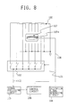
- Fig. 8 is a diagram showing the structure of the coordinate reading system of the prior art.
- a tablet acting as a coordinate reading plate there are laid a plurality of sense line groups 101 which have loop shapes.
- the tablet is not explicitly shown in Fig. 8.
- the sense line groups are selected one by one by a scanning circuit 102.
- This scanning circuit 102 has its output connected with a signal processing circuit 105, the output of which in turn is connected with a control circuit 106.
- This control circuit 106 feeds a scanning signal s101 to select the aforementioned scanning circuit 102 sequentially.
- a coordinate indicator 107 has a coil 107a packaged therein and is connected through an excitation signal line 108 with an excitation signal generating circuit 104 which is packaged in the tablet.
- the coordinate indicator 107 is placed on the sense line groups 101 and generates an AC magnetic field at all times in response to the signal of the excitation signal generating circuit 104.
- the control circuit 106 feeds the scanning signal s101 to select the scanning circuit 102 sequentially. Since an indication current according to the position of the coordinate indicator 107, an induction signal s102 for each sense line is sequentially inputted to the signal processing circuit 105 by selecting the sense line groups 101 with the scanning circuit 102.
- the signal processing circuit 105 generates an enveloping waveform of those induction signals.
- the control circuit 106 determines the coordinate values by inputting the amplitudes of the induction signals for the individual sense lines from the enveloping waveform and by comparing the amplitudes arithmetically.
- the AC signal has to be fed to the coordinate indicator so as to generate the magnetic field from the coordinate indicator.
- the tablet and the coordinate indicator have to be connected through a signal line.
- the present invention has been solved to solve the aforementioned problems in the coordinate reading system of the prior art and has an object to provide a wireless coordinate reading system which need not have its coordinate indicator and tablet connected through the signal line.
- the coordinate reading system is constructed to have the following structure.
- a wireless coordinate reading system comprising: a plurality of sense line groups laid at an equal distance from and in parallel with one another in a direction to detect coordinates; a first excitation line having zigzag connected conductor groups laid at an equal distance from and in parallel with one another in a direction to intersect said sense line groups at a right angle; a second excitation line made similar to said first excitation line and having conductors laid with a displacement of one half of the distance of the conductors of said first excitation line; an excitation signal generating circuit for feeding said first excitation line and said second excitation line with an AC signal; an excitation selecting circuit for selecting one of said first excitation line and said second excitation line to connect said excitation line with said excitation signal generating circuit; a scanning circuit for selecting one sense line from said sense line groups; a coordinate indicator including: a coil placed on said sense line groups and adapted to be electromagnetically coupled with said first and second excitation lines and said sense line groups; and
- the two excitation lines, the sense line groups, the excitation selecting circuit and the scanning circuit in the first structure are provided in each of the X- and Y-directions of the orthogonal X-Y coordinate system, and the control circuit is constructed in each of the X- and Y-directions.
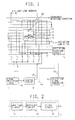
- Fig. 1 is a diagram showing the structure of the first embodiment of the coordinate reading system according to the present invention
- Fig. 2 is a diagram showing the structure of the signal processing circuit
- Fig. 3 is a diagram illustrating the distribution of the induction signal
- Fig. 4 is a diagram showing the induction signal
- Fig. 5 is a diagram showing the enveloping line signal
- Figs. 6(a) to 6(c) are diagrams showing the distributions of the induction signals against the coil position
- Fig. 7 is a diagram showing the value Q against the coil position
- Fig. 8 is a diagram showing the structure of the coordinate reading system of the prior art.
- the control circuit feeds the scanning signals to the excitation selecting circuit and the scanning circuit. As a result, one of the two excitation lines and one sense line are selected. One of the excitation lines thus selected is connected with the excitation signal generating circuit to generate the AC magnetic field, whereas the sense line is connected with the signal processing circuit.
- the coordinate indicator is placed on the sense line so as to indicate the position. If this coordinate indicator is placed in the vicinity of the two sense lines selected as above, a induction signal is generated in the selected sense line by the electromagnetically couplings between the excitation line and the coil in the coordinate indicator and between the coil and the sense line, because this coordinate indicator is made resonant with the excitation signal.
- the control circuit selects the two excitation lines alternately by a method according to the necessity, and selects the sense lines sequentially. Since the sense line generates the induction signal according to the position of the coordinate indicator, the induction signals for the individual sense lines are sequentially inputted to the signal processing circuit. This signal processing circuit generates the enveloping waveform according to the amplitudes of those induction signals. The control circuit determined the coordinate values by inputting the amplitudes of the induction signals for the individual sense lines from the enveloping waveform and by comparing the amplitudes arithmetically.
- FIG. 1 A first embodiment of the present invention will be described in the following with reference to Figs. 1 to 7.
- This structure is directed to a coordinate reading system for achieving the one-dimensional coordinate values.
- the coordinate reading system is roughly divided into a coordinate reading plate called the "tablet" and a coordinate indicator.
- This coordinate indicator can be freely moved on the tablet and used to indicate the position, the coordinate values of which are to be read out.
- FIGs. 1 and 2 are diagrams showing the structure of the coordinate reading system according to the present invention.
- reference numeral 1 designates sense line groups.
- the individual sense lines are laid in the tablet at an equal distance from and in parallel with one another.
- the distance between the sense lines is a sense line pitch ps.
- the individual sense lines have their one-side ends connected with one another and grounded to the earth. The other ends are individually connected with a scanning circuit 4.
- Numeral 2 designates a first excitation line
- numeral 3 designates a second excitation line.
- These excitation lines are also laid on the tablet and have a plurality of zigzag connected conductors which are laid at an equal distance from and in parallel with one another in the direction perpendicular to the coordinate detecting direction. If the distance of the conductors is designated at an excitation line pitch pd, the first and second excitation lines are laid at a distance of pd/2.
- the excitation lines have their one-side ends grounded to the earth and their other ends connected with the excitation selecting circuit 5.
- the scanning circuit 4 and the excitation selecting circuit 5 are composed of a plurality of electronic switch elements such as analog switches, the one-side ends of which are connected with one another to provide a common terminal. In response to a selection signal, one of the switch elements is closed to connect the one-side ends with the common terminal.
- the scanning circuit 4 has its individual terminals connected with the individual sense lines of the aforementioned sense line groups 1. Moreover, the common terminal of the scanning circuit 4 is connected with the input of a signal processing circuit 7.
- the structure of the signal processing circuit 7 is shown in Fig. 2.
- This signal processing circuit 7 is composed of an amplifier circuit 71, a rectifier circuit 72 and a filter circuit 73.
- the signal processing circuit 5 functionally generates the enveloping line of the input signals and can have a structure different from that shown in Fig. 2. It is conceivable to change the arrangement of the amplifier circuit or to provide a plurality of amplifier circuits by considering the S/N ratios, for example, but the structure is essentially identical to that of Fig. 2.
- the excitation selecting circuit 5 has its common terminal connected with an excitation signal generating circuit 6. This circuit 6 feeds an excitation signal s2 or an AC signal to the excitation line which is selected by the excitation selecting circuit 5.
- the excitation signal s2 is an AC signal of about 614.4 KHz, for example. However, this signal should not have its frequency restricted to that value but may basically generate an electromagnetic induction between the excitation lines and the sense lines and a later-described coil.
- a control circuit 8 is connected with the scanning circuit 4 and the excitation selecting circuit 3 so as to feed them with selection signals.
- the selection signal to be fed to the scanning circuit 4 is the "sense address s3", and the selection signal to be fed to the excitation selecting circuit 5 is called the "drive address s4".
- the control circuit 8 outputs the sense address s3 and the drive address s4. Specifically, one sense line is connected with the signal processing circuit 7 whereas the other is connected with the excitation signal generating circuit 6.
- the control circuit 8 is further fed with an enveloping line signal s5 from the signal processing circuit 7.
- This input unit is an A/D converter for reading the voltage value of the enveloping line signal s5 as a digital quantity.
- a coordinate indicator 9 is composed of a coil 91 and a capacitor 92 to constitute a parallel resonant circuit.
- the resonant frequency is equal to that of the excitation signal s2 which is generated by the excitation signal generating circuit 6.
- the control circuit 8 feeds the excitation selecting circuit 5 with the drive address s4 and connects one of the excitation line groups with the excitation signal generating circuit 6. After this, the control circuit 8 feeds the scanning circuit 4 with the sense address s3 to connect one of the sense line groups 1 with the signal processing circuit 7.
- Fig. 3 shows the amplitude of the induction signal which is induced in the sense line corresponding to the position of the coil 91 when the coil 91 moves along the coordinate detecting direction.
- the following description is directed to the case in which the coil 91 is between the parallel conductors of the first excitation line 2 selected, i.e., a line y1 in Fig. 3. Now, let the case be considered, in which the coil 91 is placed in the vicinity of the selected sense line.
- the first excitation line 2 is connected with the excitation signal generating circuit 6 by the excitation selecting circuit 5 to generate an AC magnetic field.
- the coil 91 generates the induction signal by the electromagnetic coupling with the first excitation line 2, and the selected sense line 1s generates the induction with by the electromagnetic coupling with the coil 91.
- FIG. 3 illustrates that the induction signal takes an amplitude Vx when the coil 91 is in a position x.
- the coil 91 In case the coil 91 is on the conductor of the first excitation line 2 selected, it does not generate the induction signal. This is because the coil has the same areas of the two regions to be divided by the conductors of the excitation line so that the inductions are canceled by the magnetic fluxes passing through the two regions and having the opposite phases. As a result, no induction signal is also generated on the sense line.
- the two excitation lines i.e., the first and second excitation lines are provided and are alternately selected by the excitation selecting circuit 5 so that the induction signal is generated even in an arbitrary position in the coil 91.
- the induction signal is generated on the sense line by selecting the excitation line and the sense line.
- the amplitude of this induction signal contains the information concerning the position, in which the coil 91 is placed. This information is utilized to determine the position by the present coordinate reading system.
- the control circuit 8 selects the excitation lines alternately and selects the sense lines sequentially each time it selects one excitation line. Usually, the control circuit 6 selects them sequentially one by one in the coordinate detecting direction or in the opposite direction. However, this selecting sequence is not an essential problem. The sequence need not be orderly but may be random. The following description resorts the orderly sequence in the coordinate detecting direction.
- one excitation sense line By one selecting operation, one excitation sense line. Since the detection sense line generates an induction signal depending upon the positional relation to the coil 91, as has been described hereinbefore, the induction signal s1 is sequentially inputted to the signal processing circuit 7 by selecting the sense lines sequentially.
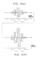
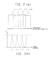
- the induction signal s1 to be inputted to the signal processing circuit 7 is illustrated in Fig. 4.
- the coil 91 is present in the vicinity of the sense line of the sense address Lx.
- the signal to be induced in the sense line is higher when the second excitation line 3 than that when the first excitation line 2 is excited. This is because of the positional relation between the coil 91 and the two excitation lines.
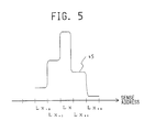
- the induction signal s1 is amplified and detected and is converted into an enveloping line by the signal processing circuit 7.
- the signal processing circuit 7 is a traditional AM detecting circuit.
- the induction signal s1, as shown in Fig. 4, is converted into the enveloping line signal s5 shown in Fig. 5.
- the method of calculating the coordinates from the enveloping line of the induction signal can be realized by the coordinate reading system of the prior art, such as the method disclosed in Japanese Patent Laid-Open No. 96411/1980, as will be briefly described in the following.
- the control circuit 8 receives the enveloping line signal s5 from the signal processing circuit 7 each time the sense line groups 1 are sequentially selected.
- the input circuit of the control circuit 8 is the A/D converter, as has been described hereinbefore, and the magnitude of the enveloping line signal s5 is inputted in terms of a digital quantity.
- the control circuit 8 detects the maximum signal and the signals of the two adjacent sense lines from the enveloping line signals s5 which are sequentially inputted.
- the individual signals are coded in the following manner.
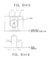
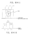
- the coil is placed at a point a, i.e, at the center of the sense line Lj, as shown in Fig. 6(a).
- letter L* designates a sense address.
- the maximum induction signal is generated during the scanning on the detection sense line Lj, and the peak signal Vp is inputted to the control circuit 8.
- the sense line Li is selected.
- a signal lower than Vp is induced in the loop line Li, and the signal Vp1 is inputted to the control circuit 8.
- a loop line Lk is selected, and the signal Vph is inputted to the control circuit 8.
- the value is determined from Equation 1 by exchanging the signals Vph and Vp1.
- the changing tendency of the value Q is also identical in this case.
- the value Q is between 1 to 0 for each one half pitch of the sense line and corresponds one-to-one to the detailed position between the sense lines. If the characteristics of the value Q are experimentally determined in advance, the detailed position between the sense lines can be determined by determining the value Q from the induction signal.
- the coordinate value is determined by adding and subtracting the rough position at the peak address and the detailed position determined herein.
- the codes will be explained again:
- the maximum signal during the scanning is adopted as the signal Vp.
- the maximum signals Vp1 and Vp2 for the individual two excitation lines are detected, when the sense line is selected for each of the two excitation lines, so that the larger one of the two is adopted.
- the coordinate values can be likewise determined if the signals Vp, Vp1 and Vph are defined, as follows:
- the scanning follows the procedure, in which the sense line is selected after one excitation line.
- the selecting procedures of the excitation line and the sense line may be such that two excitation lines are sequentially selected after the sense lines.
- the control circuit 8 outputs the sense address s3 and the drive address s4 by itself so that the correspondence of the induction signal s1 to the sense line is achieved without any trouble.
- the sequence of selecting the excitation lines and the sense lines is not an essential problem in the present invention.
- the two-dimensional coordinate reading system can be constructed.
- the X sense line group, the first X excitation line, the second X excitation line, the X scanning circuit, and the X excitation selecting circuit; and the Y sense line group, the first Y excitation line, the second Y excitation line, the Y scanning circuit and the Y excitation selecting circuit are provided and constructed likewise the first embodiment in the X and Y directions and are arranged at a right angle, although their operations will be omitted.
- two sets of zigzag excitation lines are provided and are alternately excited to determine the position of the coil from the induction signals coming from the electromagnetic couplings between the excitation line and the coil and between the coil and the sense line. Since no signal is fed to the coil packaged in the coordinate indicator unlike the coordinate reading system of the prior art, it is possible to realize a wireless coordinate reading system which need not connect the coordinate indicator and the tablet through the signal lines.
Landscapes
- Engineering & Computer Science (AREA)
- Physics & Mathematics (AREA)
- General Engineering & Computer Science (AREA)
- Theoretical Computer Science (AREA)
- Electromagnetism (AREA)
- Human Computer Interaction (AREA)
- General Physics & Mathematics (AREA)
- Measurement Of Length, Angles, Or The Like Using Electric Or Magnetic Means (AREA)
Abstract
An electromagnetic wireless induction type coordinate reading system for inputting coordinates to an external device such as a computer comprises a coil which is electromagnetically coupled with loop line groups. A resonator is adapted to resonate with the AC signal generated by an excitation signal generating circuit. The position of the coil is determined by controlling the loop line groups sequentially in order to select one of two adjacent loop lines whereas the other loop line is temporarily selected by a detection scanning circuit. The amplitudes of the signals induced on the individual loop lines are processed arithmetically.
There are two sets of zigzag excitation lines which are alternately excited to determine the position of the coil.
Description
- The present invention relates to a coordinate reading system for inputting coordinates to an external device such as a computer and, more particularly, to an electromagnetic induction type coordinate system applying the electromagnetic induction phenomenon.
- The coordinate reading system of the prior art is exemplified by our Japanese Patent Laid-Opens Nos. 96825/1977 and 96411/1980.
- These coordinate reading systems will be briefly described in the following.
- Fig. 8 is a diagram showing the structure of the coordinate reading system of the prior art. In a tablet acting as a coordinate reading plate, there are laid a plurality of
sense line groups 101 which have loop shapes. The tablet is not explicitly shown in Fig. 8. The sense line groups are selected one by one by ascanning circuit 102. Thisscanning circuit 102 has its output connected with asignal processing circuit 105, the output of which in turn is connected with acontrol circuit 106. Thiscontrol circuit 106 feeds a scanning signal s101 to select theaforementioned scanning circuit 102 sequentially. On the other hand, acoordinate indicator 107 has a coil 107a packaged therein and is connected through anexcitation signal line 108 with an excitationsignal generating circuit 104 which is packaged in the tablet. - With the structure thus made, the coordinate values are calculated in the following manner. The
coordinate indicator 107 is placed on thesense line groups 101 and generates an AC magnetic field at all times in response to the signal of the excitationsignal generating circuit 104. Thecontrol circuit 106 feeds the scanning signal s101 to select thescanning circuit 102 sequentially. Since an indication current according to the position of thecoordinate indicator 107, an induction signal s102 for each sense line is sequentially inputted to thesignal processing circuit 105 by selecting thesense line groups 101 with thescanning circuit 102. Thesignal processing circuit 105 generates an enveloping waveform of those induction signals. Thecontrol circuit 106 determines the coordinate values by inputting the amplitudes of the induction signals for the individual sense lines from the enveloping waveform and by comparing the amplitudes arithmetically. - In this coordinate reading system of the prior art, however, the AC signal has to be fed to the coordinate indicator so as to generate the magnetic field from the coordinate indicator. For this necessity, the tablet and the coordinate indicator have to be connected through a signal line.
- The present invention has been solved to solve the aforementioned problems in the coordinate reading system of the prior art and has an object to provide a wireless coordinate reading system which need not have its coordinate indicator and tablet connected through the signal line.
- In order to solve the aforementioned problems, according to the present invention, the coordinate reading system is constructed to have the following structure.
- In order to a first structure for achieving one dimensional coordinate values, there is provided a wireless coordinate reading system comprising: a plurality of sense line groups laid at an equal distance from and in parallel with one another in a direction to detect coordinates; a first excitation line having zigzag connected conductor groups laid at an equal distance from and in parallel with one another in a direction to intersect said sense line groups at a right angle; a second excitation line made similar to said first excitation line and having conductors laid with a displacement of one half of the distance of the conductors of said first excitation line; an excitation signal generating circuit for feeding said first excitation line and said second excitation line with an AC signal; an excitation selecting circuit for selecting one of said first excitation line and said second excitation line to connect said excitation line with said excitation signal generating circuit; a scanning circuit for selecting one sense line from said sense line groups; a coordinate indicator including: a coil placed on said sense line groups and adapted to be electromagnetically coupled with said first and second excitation lines and said sense line groups; and a resonator adapted to resonate with the AC signal generated by said excitation signal generating circuit; a signal processing circuit connected with said circuit for processing an induced signal which is induced in said sense line groups by an electromagnetic coupling with said coordinate indicator; and a control circuit for determining the coordinates of the position, in which said coordinate indicator is placed, by performing such controls that one of said first excitation line and said second excitation line is selected by said excitation selecting circuit whereas said sense lines are sequentially selected by said scanning circuit, and by inputting the induced signals, which are induced on the individual sense lines, sequentially from said signal processing circuit to process the amplitudes of said induced signals arithmetically.
- According to a second structure for achieving two-dimensional coordinate values, the two excitation lines, the sense line groups, the excitation selecting circuit and the scanning circuit in the first structure are provided in each of the X- and Y-directions of the orthogonal X-Y coordinate system, and the control circuit is constructed in each of the X- and Y-directions.
- Fig. 1 is a diagram showing the structure of the first embodiment of the coordinate reading system according to the present invention; Fig. 2 is a diagram showing the structure of the signal processing circuit; Fig. 3 is a diagram illustrating the distribution of the induction signal; Fig. 4 is a diagram showing the induction signal; Fig. 5 is a diagram showing the enveloping line signal; Figs. 6(a) to 6(c) are diagrams showing the distributions of the induction signals against the coil position; Fig. 7 is a diagram showing the value Q against the coil position; and Fig. 8 is a diagram showing the structure of the coordinate reading system of the prior art.
- The operations of the first structure will be described in the following.
- The control circuit feeds the scanning signals to the excitation selecting circuit and the scanning circuit. As a result, one of the two excitation lines and one sense line are selected. One of the excitation lines thus selected is connected with the excitation signal generating circuit to generate the AC magnetic field, whereas the sense line is connected with the signal processing circuit.
- On the other hand, the coordinate indicator is placed on the sense line so as to indicate the position. If this coordinate indicator is placed in the vicinity of the two sense lines selected as above, a induction signal is generated in the selected sense line by the electromagnetically couplings between the excitation line and the coil in the coordinate indicator and between the coil and the sense line, because this coordinate indicator is made resonant with the excitation signal.
- The control circuit selects the two excitation lines alternately by a method according to the necessity, and selects the sense lines sequentially. Since the sense line generates the induction signal according to the position of the coordinate indicator, the induction signals for the individual sense lines are sequentially inputted to the signal processing circuit. This signal processing circuit generates the enveloping waveform according to the amplitudes of those induction signals. The control circuit determined the coordinate values by inputting the amplitudes of the induction signals for the individual sense lines from the enveloping waveform and by comparing the amplitudes arithmetically.
- A first embodiment of the present invention will be described in the following with reference to Figs. 1 to 7. This structure is directed to a coordinate reading system for achieving the one-dimensional coordinate values.
- Although not explicitly shown, the coordinate reading system is roughly divided into a coordinate reading plate called the "tablet" and a coordinate indicator. This coordinate indicator can be freely moved on the tablet and used to indicate the position, the coordinate values of which are to be read out.
- First of all, the structure will be described in the following. Figs. 1 and 2 are diagrams showing the structure of the coordinate reading system according to the present invention.
- As shown,
reference numeral 1 designates sense line groups. The individual sense lines are laid in the tablet at an equal distance from and in parallel with one another. The distance between the sense lines is a sense line pitch ps. The individual sense lines have their one-side ends connected with one another and grounded to the earth. The other ends are individually connected with ascanning circuit 4. -
Numeral 2 designates a first excitation line, and numeral 3 designates a second excitation line. These excitation lines are also laid on the tablet and have a plurality of zigzag connected conductors which are laid at an equal distance from and in parallel with one another in the direction perpendicular to the coordinate detecting direction. If the distance of the conductors is designated at an excitation line pitch pd, the first and second excitation lines are laid at a distance of pd/2. The excitation lines have their one-side ends grounded to the earth and their other ends connected with theexcitation selecting circuit 5. - The
scanning circuit 4 and theexcitation selecting circuit 5 are composed of a plurality of electronic switch elements such as analog switches, the one-side ends of which are connected with one another to provide a common terminal. In response to a selection signal, one of the switch elements is closed to connect the one-side ends with the common terminal. - The
scanning circuit 4 has its individual terminals connected with the individual sense lines of the aforementionedsense line groups 1. Moreover, the common terminal of thescanning circuit 4 is connected with the input of asignal processing circuit 7. - The structure of the
signal processing circuit 7 is shown in Fig. 2. Thissignal processing circuit 7 is composed of anamplifier circuit 71, arectifier circuit 72 and afilter circuit 73. Thesignal processing circuit 5 functionally generates the enveloping line of the input signals and can have a structure different from that shown in Fig. 2. It is conceivable to change the arrangement of the amplifier circuit or to provide a plurality of amplifier circuits by considering the S/N ratios, for example, but the structure is essentially identical to that of Fig. 2. - The
excitation selecting circuit 5 has its common terminal connected with an excitationsignal generating circuit 6. Thiscircuit 6 feeds an excitation signal s2 or an AC signal to the excitation line which is selected by theexcitation selecting circuit 5. The excitation signal s2 is an AC signal of about 614.4 KHz, for example. However, this signal should not have its frequency restricted to that value but may basically generate an electromagnetic induction between the excitation lines and the sense lines and a later-described coil. - A
control circuit 8 is connected with thescanning circuit 4 and the excitation selecting circuit 3 so as to feed them with selection signals. The selection signal to be fed to thescanning circuit 4 is the "sense address s3", and the selection signal to be fed to theexcitation selecting circuit 5 is called the "drive address s4". Thecontrol circuit 8 outputs the sense address s3 and the drive address s4. Specifically, one sense line is connected with thesignal processing circuit 7 whereas the other is connected with the excitationsignal generating circuit 6. - The
control circuit 8 is further fed with an enveloping line signal s5 from thesignal processing circuit 7. This input unit is an A/D converter for reading the voltage value of the enveloping line signal s5 as a digital quantity. - A coordinate indicator 9 is composed of a
coil 91 and acapacitor 92 to constitute a parallel resonant circuit. The resonant frequency is equal to that of the excitation signal s2 which is generated by the excitationsignal generating circuit 6. - Next, the operations will be described in the following.
- The
control circuit 8 feeds theexcitation selecting circuit 5 with the drive address s4 and connects one of the excitation line groups with the excitationsignal generating circuit 6. After this, thecontrol circuit 8 feeds thescanning circuit 4 with the sense address s3 to connect one of thesense line groups 1 with thesignal processing circuit 7. - Here, when the coordinate indicator 9 comes close to the selected sense line, the properties of the induction signal to be induced by the sense line will be described with reference to Fig. 3. The magnitude of the induction signal is a function of the position of the coil in the coordinate detecting direction and the position at a right angle with respect to the former. Fig. 3 shows the amplitude of the induction signal which is induced in the sense line corresponding to the position of the
coil 91 when thecoil 91 moves along the coordinate detecting direction. - First of all, the following description is directed to the case in which the
coil 91 is between the parallel conductors of thefirst excitation line 2 selected, i.e., a line y1 in Fig. 3. Now, let the case be considered, in which thecoil 91 is placed in the vicinity of the selected sense line. Thefirst excitation line 2 is connected with the excitationsignal generating circuit 6 by theexcitation selecting circuit 5 to generate an AC magnetic field. Thecoil 91 generates the induction signal by the electromagnetic coupling with thefirst excitation line 2, and the selectedsense line 1s generates the induction with by the electromagnetic coupling with thecoil 91. - As the
coil 91 goes apart from the selectedsense line 1s, the induction signal to be induced on thesense line 1s has its amplitude reduced. Fig. 3 illustrates that the induction signal takes an amplitude Vx when thecoil 91 is in a position x. - In case the
coil 91 is on the conductor of thefirst excitation line 2 selected, it does not generate the induction signal. This is because the coil has the same areas of the two regions to be divided by the conductors of the excitation line so that the inductions are canceled by the magnetic fluxes passing through the two regions and having the opposite phases. As a result, no induction signal is also generated on the sense line. In the coordinate reading system according to the present invention, the two excitation lines, i.e., the first and second excitation lines are provided and are alternately selected by theexcitation selecting circuit 5 so that the induction signal is generated even in an arbitrary position in thecoil 91. - Thus, the induction signal is generated on the sense line by selecting the excitation line and the sense line. The amplitude of this induction signal contains the information concerning the position, in which the
coil 91 is placed. This information is utilized to determine the position by the present coordinate reading system. - The
control circuit 8 selects the excitation lines alternately and selects the sense lines sequentially each time it selects one excitation line. Usually, thecontrol circuit 6 selects them sequentially one by one in the coordinate detecting direction or in the opposite direction. However, this selecting sequence is not an essential problem. The sequence need not be orderly but may be random. The following description resorts the orderly sequence in the coordinate detecting direction. - By one selecting operation, one excitation sense line. Since the detection sense line generates an induction signal depending upon the positional relation to the
coil 91, as has been described hereinbefore, the induction signal s1 is sequentially inputted to thesignal processing circuit 7 by selecting the sense lines sequentially. - The induction signal s1 to be inputted to the
signal processing circuit 7 is illustrated in Fig. 4. In this example, it is indicated that thecoil 91 is present in the vicinity of the sense line of the sense address Lx. The signal to be induced in the sense line is higher when the second excitation line 3 than that when thefirst excitation line 2 is excited. This is because of the positional relation between thecoil 91 and the two excitation lines. - The induction signal s1 is amplified and detected and is converted into an enveloping line by the
signal processing circuit 7. As has been described hereinbefore, thesignal processing circuit 7 is a traditional AM detecting circuit. The induction signal s1, as shown in Fig. 4, is converted into the enveloping line signal s5 shown in Fig. 5. - The method of calculating the coordinates from the enveloping line of the induction signal can be realized by the coordinate reading system of the prior art, such as the method disclosed in Japanese Patent Laid-Open No. 96411/1980, as will be briefly described in the following.
- The
control circuit 8 receives the enveloping line signal s5 from thesignal processing circuit 7 each time thesense line groups 1 are sequentially selected. The input circuit of thecontrol circuit 8 is the A/D converter, as has been described hereinbefore, and the magnitude of the enveloping line signal s5 is inputted in terms of a digital quantity. - The
control circuit 8 detects the maximum signal and the signals of the two adjacent sense lines from the enveloping line signals s5 which are sequentially inputted. The individual signals are coded in the following manner. - Vp - - -
- the maximum signal called the "peak signal";
- Vph - - -
- the signal on the sense line which is adjacent in the coordinate detecting direction to the sense line having generated the maximum signal; and
- Vp1 - - -
- the signal on the sense line which is inversely adjacent in the coordinate detecting direction to the sense line having generated the maximum signal.
- For this determination, the following value Q is calculated:

wherein Vph > Vp1.
This value Q has the following properties. - Let it be considered that the coil is placed at a point a, i.e, at the center of the sense line Lj, as shown in Fig. 6(a). Here, letter L* designates a sense address. At this time, the maximum induction signal is generated during the scanning on the detection sense line Lj, and the peak signal Vp is inputted to the
control circuit 8. The peak address takes Padrs = Lk. In the selection of one time before, the sense line Li is selected. In this case, a signal lower than Vp is induced in the loop line Li, and the signal Vp1 is inputted to thecontrol circuit 8. In the selection of one time after, a loop line Lk is selected, and the signal Vph is inputted to thecontrol circuit 8. In the selections of one time before and after, the effects of the electromagnetic couplings are equal, i.e., Vph = Vp1, although the detail will be omitted. As a result, Q = 1 is obtained fromEquation 1. - If the coil moves in the coordinate detecting direction, as shown in Fig. 6(b), the couplings of Li and Lj are reduced in accordance with the scanning sequence, but the coupling of Lk is increased. As a result, the signals Vp and Vp1 are reduced whereas the signal Vph is increased, so that the value Q of
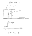
Equation 1 takes a value smaller than 1. - When the coil moves more to the position of Fig. 6(c), i.e., one half of the sense line pitch ps from the position of Fig. 6(a), the value Q takes the minimum. At this time, the effects of the couplings of Lj and Lk are equalized so that Vp = Vph and Q = 0.
- In case of further leftward movement from the position of Fig. 6(a), the value is determined from
Equation 1 by exchanging the signals Vph and Vp1. The changing tendency of the value Q is also identical in this case. - The value Q is between 1 to 0 for each one half pitch of the sense line and corresponds one-to-one to the detailed position between the sense lines. If the characteristics of the value Q are experimentally determined in advance, the detailed position between the sense lines can be determined by determining the value Q from the induction signal.
- The coordinate value is determined by adding and subtracting the rough position at the peak address and the detailed position determined herein. The following
Equation 2 calculates the coordinates:

wherein Vph > Vp1, or
Coordinate Value = Padrs x ps - f(Q);
wherein Vph < Vp1.
Here, the codes will be explained again: - Padrs:
- the peak address;
- ps:
- the sense line pitch; and
- f(Q):
- the detailed position corresponding to the value Q and between the sense lines.
- In the foregoing embodiment, the maximum signal during the scanning is adopted as the signal Vp. In more detail, the maximum signals Vp1 and Vp2 for the individual two excitation lines are detected, when the sense line is selected for each of the two excitation lines, so that the larger one of the two is adopted.
- As another example of the processing, the coordinate values can be likewise determined if the signals Vp, Vp1 and Vph are defined, as follows:
- Vp1:
- the maximum signal when the first exitation line is selected;
- Vph1:
- the signal on the sense line which is adjacent in the coordinate detecting direction to the sense line having generated the maximum signal when the first excitation line is selected;
- Vp11:
- the signal on the sense line which is inversely adjacent in the coordinate detecting direction to the sense line having generated the maximum signal when the first excitation line is selected;
- Vp2:
- the maximum signal when the second exitation line is selected;
- Vph2:
- the signal on the sense line which is adjacent in the coordinate detecting direction to the sense line having generated the maximum signal when the second excitation line is selected; and
- Vp12:
- the signal on the sense line which is inversely adjacent in the coordinate detecting direction to the sense line having generated the maximum signal when the second excitation line is selected,
- In the description of the first embodiment, the scanning follows the procedure, in which the sense line is selected after one excitation line. The selecting procedures of the excitation line and the sense line may be such that two excitation lines are sequentially selected after the sense lines. Although, in this case, the sequence of the induction signal s1 to be inputted to the
signal processing circuit 7 changes, thecontrol circuit 8 outputs the sense address s3 and the drive address s4 by itself so that the correspondence of the induction signal s1 to the sense line is achieved without any trouble. The sequence of selecting the excitation lines and the sense lines is not an essential problem in the present invention. - If two sets of sense line groups, first and second excitation lines, excitation selecting circuits and scanning circuits are provided and constructed, as has been described in connection with the first embodiment so that they are arranged at a right angle, it is apparent that the two-dimensional coordinate reading system can be constructed. Although not shown, the X sense line group, the first X excitation line, the second X excitation line, the X scanning circuit, and the X excitation selecting circuit; and the Y sense line group, the first Y excitation line, the second Y excitation line, the Y scanning circuit and the Y excitation selecting circuit are provided and constructed likewise the first embodiment in the X and Y directions and are arranged at a right angle, although their operations will be omitted.
- As has been described hereinbefore, according to the present invention, two sets of zigzag excitation lines are provided and are alternately excited to determine the position of the coil from the induction signals coming from the electromagnetic couplings between the excitation line and the coil and between the coil and the sense line. Since no signal is fed to the coil packaged in the coordinate indicator unlike the coordinate reading system of the prior art, it is possible to realize a wireless coordinate reading system which need not connect the coordinate indicator and the tablet through the signal lines.
As to the sense line having generated the maximum signal, its detected address is also stored and called the "peak address", as designated Padrs. The peak address roughly indicates the position in which the coordinate indicator is placed. This makes it possible to detect the position at the unit of the sense line pitch. A finer position is determined by calculating the peak signal and its two adjacent signals.
Vph = Vph1 + Vph2
Vp1 = Vp11 + Vp2.
The Equation (3) implies the signals Vp, Vph and Vp1 are determined in the one-dimensional form of the signals detected by the individual excitation lines, and may be an averaging calculation or the like.
Claims (2)
- A wireless coordinate reading system comprising:a. a plurality of sense line groups laid at an equal distance from and in parallel with one another in a direction to detect coordinates;b. a first excitation line having zigzag connected conductor groups laid at an equal distance from and in parallel with one another in a direction to intersect said sense line groups at a right angle;c. a second excitation line made similar to said first excitation line and having conductors laid with a displacement of one half of the distance of the conductors of said first excitation line;d. an excitation signal generating circuit for feeding said first excitation line and said second excitation line with an AC signal;e. an excitation selecting circuit for selecting one of said first excitation line and said second excitation line to connect said excitation line with said excitation signal generating circuit;f. a scanning circuit for selecting one sense line from said sense line groups;g. a coordinate indicator including: a coil placed on said sense line groups and adapted to be electromagnetically coupled with said first and second excitation lines and said sense line groups; and a resonator adapted to resonate with the AC signal generated by said excitation signal generating circuit;h. a signal processing circuit connected with said circuit for processing an induced signal which is induced in said sense line groups by an electromagnetic coupling with said coordinate indicator; andi. a control circuit for determining the coordinates of the position, in which said coordinate indicator is placed, by performing such controls that one of said first excitation line and said second excitation line is selected by said excitation selecting circuit whereas said sense lines are sequentially selected by said scanning circuit, and by inputting the induced signals, which are induced on the individual sense lines, sequentially from said signal processing circuit to process the amplitudes of said induced signals arithmetically.
- A wireless coordinate reading system comprising:a. a plurality of sense line groups laid at an equal distance from and in parallel with one another in each of X- and Y- directions of an X-Y orthogonal coordinate system;b. a first excitation line having zigzag connected conductor groups laid at an equal distance from and in parallel with one another in a direction to intersect said sense line groups at a right angle in each of the X- and Y- directions of said X-Y orthogonal coordinate system;c. a second excitation line made similar to said first excitation line and having conductors laid with a displacement of one half of the distance of the conductors of said first excitation line in each of the X- and Y- directions of said X-Y orthogonal coordinate system;d. an excitation signal generating circuit for feeding said first excitation line and said second excitation line with an AC signal;e. an X excitation selecting circuit and a Y excitation selecting circuit for selecting one of said first excitation line and said second excitation line in each of the X- and Y- directions to connect said excitation line with said excitation signal generating circuit;signal processing circuit to process the amplitudes of said induced signals arithmetically.
Applications Claiming Priority (2)
| Application Number | Priority Date | Filing Date | Title |
|---|---|---|---|
| JP2125052A JPH0424717A (en) | 1990-05-15 | 1990-05-15 | Wireless coordinate reader |
| JP125052/90 | 1990-05-15 |
Publications (2)
| Publication Number | Publication Date |
|---|---|
| EP0457218A2 true EP0457218A2 (en) | 1991-11-21 |
| EP0457218A3 EP0457218A3 (en) | 1992-05-06 |
Family
ID=14900638
Family Applications (1)
| Application Number | Title | Priority Date | Filing Date |
|---|---|---|---|
| EP19910107644 Withdrawn EP0457218A3 (en) | 1990-05-15 | 1991-05-10 | Wireless coordinate reading system |
Country Status (3)
| Country | Link |
|---|---|
| US (1) | US5128499A (en) |
| EP (1) | EP0457218A3 (en) |
| JP (1) | JPH0424717A (en) |
Families Citing this family (8)
| Publication number | Priority date | Publication date | Assignee | Title |
|---|---|---|---|---|
| US5850416A (en) * | 1993-06-30 | 1998-12-15 | Lucent Technologies, Inc. | Wireless transmitter-receiver information device |
| JPH0830375A (en) * | 1994-05-13 | 1996-02-02 | Seiko Instr Inc | Coordinate reader and coordinate detecting method |
| US5714720A (en) * | 1994-09-15 | 1998-02-03 | Calcomp Inc. | High efficiency passive pointer digitizer system |
| US5914710A (en) * | 1997-08-20 | 1999-06-22 | Ace Cad Enterprise Co., Ltd. | Cordless pointing instrument for graphics tablet |
| JP2005352572A (en) * | 2004-06-08 | 2005-12-22 | Canon Inc | Coordinate input device |
| JP2007153891A (en) * | 2005-11-30 | 2007-06-21 | Kowa Co | Medicament for the suppression of chronic progressive kidney injury |
| BE1016981A3 (en) * | 2006-02-08 | 2007-11-06 | Fn Herstal Sa | IMPROVED VISOR WITH RED MOBILE BRIDGE. |
| TW201314182A (en) * | 2011-09-22 | 2013-04-01 | li-xin Huang | Charged body sensing system |
Family Cites Families (10)
| Publication number | Priority date | Publication date | Assignee | Title |
|---|---|---|---|---|
| JPS5296825A (en) * | 1976-02-10 | 1977-08-15 | Seiko Instr & Electronics Ltd | Coordinates readout unit |
| GB1601806A (en) * | 1977-05-31 | 1981-11-04 | Nippon Telegraph & Telephone | Tablet input devices |
| JPS5935069B2 (en) * | 1979-01-19 | 1984-08-27 | セイコーインスツルメンツ株式会社 | Interpolation method of coordinate reading device |
| JPS58159191A (en) * | 1982-03-17 | 1983-09-21 | Hitachi Seiko Ltd | Coordinate detector |
| JPS58191091A (en) * | 1982-05-01 | 1983-11-08 | Hitachi Seiko Ltd | Coordinate detector |
| US4697144A (en) * | 1984-04-19 | 1987-09-29 | Verify Electronics Limited | Position sensing apparatus |
| JPS61107423A (en) * | 1984-10-30 | 1986-05-26 | Wacom Co Ltd | Coordinate input device with display |
| US4729108A (en) * | 1985-09-10 | 1988-03-01 | Hitachi Seiko Ltd. | Apparatus for determining a coordinate of a given point on a tablet |
| JP2583509B2 (en) * | 1987-06-16 | 1997-02-19 | 株式会社 ワコム | Coordinate input device |
| JPH01194019A (en) * | 1988-01-29 | 1989-08-04 | Wacom Co Ltd | Position detector |
-
1990
- 1990-05-15 JP JP2125052A patent/JPH0424717A/en active Pending
-
1991
- 1991-05-10 EP EP19910107644 patent/EP0457218A3/en not_active Withdrawn
- 1991-05-15 US US07/700,235 patent/US5128499A/en not_active Expired - Fee Related
Also Published As
| Publication number | Publication date |
|---|---|
| US5128499A (en) | 1992-07-07 |
| EP0457218A3 (en) | 1992-05-06 |
| JPH0424717A (en) | 1992-01-28 |
Similar Documents
| Publication | Publication Date | Title |
|---|---|---|
| EP0389963B1 (en) | A device for determining position coordinates of points on a surface | |
| US5220324A (en) | Wireless coordinate reader and switch state detection system for coordinate indicator | |
| EP0432365A2 (en) | Low-power electromagnetic digitizer tablet | |
| EP0457218A2 (en) | Wireless coordinate reading system | |
| US4661656A (en) | Graphic tablet and method | |
| JPS5979384A (en) | Coordinate reading method | |
| EP0565852B1 (en) | Optimal scan sequence for RF magnetic digitizers | |
| EP0356496B1 (en) | Shifting wire sequence digitizer system | |
| EP0511406A1 (en) | Device for reading out coordinate | |
| US5693913A (en) | Coordinate reader and method of detecting coordinates | |
| EP0457219A2 (en) | Wireless coordinate reading system | |
| EP0256327B1 (en) | Electromagnetic induction type coordinates reader | |
| US4831216A (en) | Digitizer system with intertwined loopback conductor grid | |
| EP0511027B1 (en) | Coordinate reading system | |
| US6838872B1 (en) | Position detecting system and method | |
| US5450348A (en) | Digitizing device | |
| JPH0511918A (en) | Wireless coordinate reader | |
| JPH04322319A (en) | Wireless coordinate reader | |
| JP2625479B2 (en) | Coordinate detection device | |
| JPH0643728U (en) | Digitizer tablet | |
| JPH04326418A (en) | Relative coordinate reading device | |
| JPH08185252A (en) | Scanning method for polyphase digitizer | |
| JPH04326416A (en) | Coordinate reader | |
| JPH03175522A (en) | Coordinate reader | |
| JPH04361318A (en) | Coordinate reader |
Legal Events
| Date | Code | Title | Description |
|---|---|---|---|
| PUAI | Public reference made under article 153(3) epc to a published international application that has entered the european phase |
Free format text: ORIGINAL CODE: 0009012 |
|
| AK | Designated contracting states |
Kind code of ref document: A2 Designated state(s): DE FR GB |
|
| PUAL | Search report despatched |
Free format text: ORIGINAL CODE: 0009013 |
|
| AK | Designated contracting states |
Kind code of ref document: A3 Designated state(s): DE FR GB |
|
| STAA | Information on the status of an ep patent application or granted ep patent |
Free format text: STATUS: THE APPLICATION IS DEEMED TO BE WITHDRAWN |
|
| 18D | Application deemed to be withdrawn |
Effective date: 19921107 |