EP0457145A2 - Dropper handling device for warp threading machines - Google Patents
Dropper handling device for warp threading machines Download PDFInfo
- Publication number
- EP0457145A2 EP0457145A2 EP91107289A EP91107289A EP0457145A2 EP 0457145 A2 EP0457145 A2 EP 0457145A2 EP 91107289 A EP91107289 A EP 91107289A EP 91107289 A EP91107289 A EP 91107289A EP 0457145 A2 EP0457145 A2 EP 0457145A2
- Authority
- EP
- European Patent Office
- Prior art keywords
- rail
- magazines
- feed
- return
- swivel
- Prior art date
- Legal status (The legal status is an assumption and is not a legal conclusion. Google has not performed a legal analysis and makes no representation as to the accuracy of the status listed.)
- Granted
Links
Images


Classifications
-
- D—TEXTILES; PAPER
- D03—WEAVING
- D03J—AUXILIARY WEAVING APPARATUS; WEAVERS' TOOLS; SHUTTLES
- D03J1/00—Auxiliary apparatus combined with or associated with looms
- D03J1/14—Apparatus for threading warp stop-motion droppers, healds, or reeds
Definitions
- the present invention relates to a device for handling slats for warp threading machines, and means for storing the slats and with transport means for feeding them to a separating station, at which the slats are separated for the purpose of making them available for the warp threading.
- the invention is now to provide a device for handling slats for warp threading machines, which enables an uninterrupted automatic loading of the warp threading machine with slats.
- the means for storing the lamella magazines for receiving lamella stacks and the transport means have a first path for feeding the full magazines to the separation station and a second path for returning the empty magazines from the separation station, and that means are provided for the transfer of the empty magazines from the first to the second path.
- the first path contains a feed rail sloping down towards the separating station and the second path contains a return rail sloping downwards away from the separating station, and the manual magazines are guided in a rolling or sliding manner in the feed and return rail.
- two pairs of feed and return rails are provided, each of these pairs being assigned a means for transferring the empty magazines.
- the drawing-in machine consists of a base frame 1 and of various assemblies arranged in it, each of which forms a functional module.
- a warp beam carriage 2 with a warp beam 3 arranged on it can be seen in front of the base frame 1.
- the warp beam trolley 3 also contains a lifting device 4 for holding a frame 5, on which the warp threads KF are stretched. This clamping takes place before the actual pulling-in and at a location separate from the drawing-in machine, the frame 5 being positioned at the lower end of the lifting device 4 in the immediate vicinity of the warp beam 3.
- the warp beam carriage 2 with the warp beam 3 and lifting device 4 is moved to the so-called upgrade side of the pulling-in machine and the frame 5 is lifted up by the lifting device 4 and then assumes the position shown.
- the frame 5 and the warp beam 3 are moved in the longitudinal direction of the base frame 1. During this shifting, the warp threads KF are guided past a thread separation group 6 and are separated and divided in the process. After division, the warp threads KF are cut off and presented to a pull-in needle 7, which forms part of the so-called pull-in module.
- the sectioning device used in the USTER TOPMATIC warp knitting machine (USTER - registered trademark of Zellweger Uster AG), for example, can be used for dividing the warp threads.
- a monitor 8 which belongs to an operating station and is used to display machine functions and machine malfunctions and for data input.
- the operator station which forms part of a so-called programming module, also contains an input stage for the manual entry of certain functions, such as creeper, start / stop, repetition of processes, and the like.
- the drawing-in machine is controlled by a control module containing a control computer, which is arranged in a control box 9.
- this control box contains a module computer for each so-called main module, the individual module computers being controlled and monitored by the control computer.
- the main modules of the drawing machine are, in addition to the modules already mentioned, drawing module, yarn module, control module and programming module, the strand, the lamella and the sheet module.
- the warp threads and the individual elements in which the warp threads are to be fed are fed in on the upgrade side, and the so-called dishes (strands, lamellae and sheets) with the drawn-in warp threads can be removed on the tear-down side.
- the frame 5 with the warp threads KF and the warp beam carriage 2 with the warp beam 3 are moved past the thread separating group 6 to the right, the pull-in needle 7 successively taking out the warp threads KF stretched on the frame 5.
- the warp thread monitor slats LA Immediately behind the plane of the warp threads KF are the warp thread monitor slats LA, behind them the healds LI and even further behind the reed.
- the lamellae LA are stacked in hand magazines, and the full hand magazines are hung in inclined feed rails 11, on which they are transported to the right, towards the pull-in needle 7. There they are separated and brought into the feed position. After pulling in, the lamellae LA arrive on lamella support rails 12 on the dismantling side.
- the strands LI are lined up on rails 13 and manually or automatically shifted to a separation stage on them. Then the healds LI are individually brought into their retracted position and, after they have been drawn in, are distributed to the corresponding heald frames 14 on the dismantling side. The reed is also moved past the retracting needle 7 step by step, the corresponding gap in the sheet being opened for the retraction. After being drawn in, the sheet is also on the dismantling side. To the right of the heald frames 14 is a part of the reed WB. This representation is to be understood purely for illustrative purposes, because the reed is different from the one shown The position of the frame 5 is of course on the upgrade page.
- a so-called crockery trolley 15 is provided on the dismantling side. This is inserted together with the slat support rails 12, heald frames 14 and a holder for the reed attached to the base frame 1 in the position shown and carries the dishes with the drawn-in warp threads KF after being drawn in.
- the warp beam carriage 2 with the warp beam 3 is located directly in front of the harness carriage 15.
- the dishes are reloaded from the harness carriage 15 onto the warp beam carriage 2, which then carries the warp beam 3 and the pulled-in dishes and to the relevant weaving machine or can be moved to an interim storage facility.
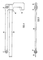
- FIGS. 2a, 2b and 3 show an overall view of this partial module in a side view (FIGS. 2a, 2b) and in a front view (FIG. 3) in the direction of arrow III of FIG 2a.
- the side view is divided into two sheets, wherein FIGS. 2a and 2b are to be thought of as abutting along the line A-A drawn on the far right in FIG. 2a and on the left in FIG. 2b.
- the slat magazine sub-module essentially consists of a movable elongated frame GE, in which the feed rails 11 for the hand magazines with the slats LA (FIG. 1) are mounted.
- the sub-module in FIGS. 2a and 2b is rotated through 180 °; its total length is about 3 meters.
- the feed rails 11 are formed by profile rails with a C-shaped cross section, into which elongated hand magazines 16 are hung. 4 and 5, these consist of a rail 18 carrying transport rollers 17, a handle 19 connected to the rail 18 and a slat rod 20 connected to the handle 19, on which the slats LA are lined up .
- the feed rails 11 run from the loading side of the submodule its unloading side, that is the separating station at which the lamellae LA are separated, obliquely downwards, so that the hand magazines 16 loaded with lamellae LA automatically roll to the separating station which is located at the left end of the submodule in FIG. 2a.
- return rails 21 are provided in the frame GE for returning the empty hand magazines from the separating station to the loading side. These run obliquely downwards away from the separating station, so that the empty hand magazines 16 roll back by themselves.
- the empty hand magazines are transferred to the return rails 21, which will be described later with reference to FIGS. 6 and 7.
- the foremost part of the feed and return rails 11 and 21, which adjoins the separating station is designed as a pivot rail 22 which can be pivoted optionally into the feed path or into the return path and whose length corresponds to the length of a hand magazine 16. It is therefore only ever located in the hand magazine 16 in the swivel rail 22, its entry and exit into and from the swivel rail being detected by sensors 23 and 28.
- the hand magazine 16 in the swivel station 22 abuts a stop with the tip of its rail 18 (FIG. 4) and is thereby fixed in the swivel rail.
- the individual lamellae LA are transferred to the separating station by moving the lamella stack lined up on the lamella rod 20 against the free end of the lamella rod. This displacement is carried out by a pneumatic cylinder 24, which drives a plunger 26 guided in a C-profile 25.
- This plunger is provided on its front part pressing against the stack of lamellae with a hinge-like driver finger 27.
- the driver finger is held in its working position by spring force, in which it stands at right angles from the plunger 26 and presses against the lamellae LA.
- the swivel rail 22 is swiveled into the return path, whereby the empty hand magazine 16 is transferred to the return rail 21 and rolls back to the right against the loading side of the lamella module.
- This movement is made by one Sensor 28 monitored on the return rail 21.
- the swivel rail 22 is swiveled into the feed path, so that a new full hand magazine 16 can roll into the swivel rail 22.
- the plunger 26 with the driver finger 27 is still in its foremost position.
- the pneumatic cylinder 24 is retracted.
- the driver finger 27 abuts against the lamellae LA and, because of its hinge-like attachment to the plunger 26, is pushed aside to the extent that it can slide along the lamellae.
- the frame GE has a central longitudinal rail 29, on which electrical connections 30 for the various sensors and pneumatic connections 31 for the various pneumatically driven adjusting elements are arranged.
- 29 supports 32 for the C-profiles 25 are attached to the central longitudinal rail 29.
- Each swivel rail 22 is articulated on its end face adjacent to the separating station to the central longitudinal rail 29 and is adjustable via a pneumatically driven lever 33 which is fastened to the frame GE.
- FIG. 3 shows the different positions of the two swivel rails 22, the swivel positions being drawn approximately in the region of the sensor 23, that is to say at the location of the maximum deflection of the swivel rails 22, for a clearer illustration. This is the place where the respective end of the swivel rails 22 is aligned with the associated feed or return rail 11 or 21.
- the swivel rail 22 is in the fully extended position in the feed path, the position shown in broken lines corresponds to the return path.
- the swivel rail 22 is in the fully extended position in the return path, the position shown in broken lines corresponds to the feed path.
- the left half shows a full hand magazine 16 with lamellae LA, which are pushed against the viewer by the pneumatic cylinder 24 via plunger 26 and driver 27.
- the right half shows an empty hand magazine 16, the slats of which have already been processed.
- the frame GE is provided with wheels 34 which run in corresponding rails 35.
- the frame GE and thus the entire lamella module are mobile on the one hand, that is to say they can be moved into and out of the drawing-in machine, and on the other hand can be fixed in the drawing-in machine in its working position.
- FIGS. 6 and 7 show the connection between the feed and return rails 11 and 21 on the one hand and the swivel rail 22 on the other hand, FIG. 6 being an enlarged detail from FIG. 2a and thus a side view and FIG. 7 a plan view in the direction of the arrow VII of Fig. 6 shows.
- a pivotable stop flap 36 for the hand magazines 16 is arranged on the end of the feed rails 11 facing the swivel rail 22.
- An arcuate groove 37 is milled into this stop flap, into which a locking bolt 38 engages, and which has a step 39 recessed at its upper end with respect to the base of the groove.
- the locking bolt 38 is arranged on one end face of a cylinder 40 which is resiliently mounted in a bore in the central longitudinal rail 29 and its length corresponds to the depth of the groove 38 plus step 39.
- the locking bolt 38 projects with its entire length into the groove 37 and step 39 and thereby locks the stop flap 36, as a result of which this occurs in the adjacent feed rail 11 in the transport direction, the foremost hand magazine 16 is prevented from rolling further (FIG. 6). If the swivel rail 22 is then swiveled into the feed path and aligned with the feed rail 11 (FIG. 7, upper half), then the swivel rail 22 also hits its side surface facing the central longitudinal rail onto the cylinder 40 and presses it against the force of its spring into its bearing bore, as a result of which the locking bolt 38 is pulled out of the step 39 of the groove 37.
- the corresponding adjustment path of cylinder 40 and locking bolt 38 is somewhat greater than the depth of the gradation 39, so that the locking bolt 38 no longer protrudes into the gradation and the stop flap 36 is therefore no longer locked.
- the stop flap 36 is pressed upwards by the foremost hand magazine 16 and this can roll into the swivel rail 22.
- the pressure of the swivel rail 22 on the cylinder 40 is released and the locking bolt 38 can snap back into the step 39 and lock the stop flap 36.
- the lamella module In its working position, the lamella module is detachably coupled to the drawing-in machine. In this working position, the loading of full magazines and the removal of the empty magazines takes place in the drawing-in machine, from which the lamella carriage is only removed for maintenance or service work.
Abstract
Die Vorrichtung enthält Magazine (16) zur Aufnahme von Lamellenstapeln (LA) und Transportmittel zu deren Zuführung an eine Separierstation, an welche eine Vereinzelung der Lamellen erfolgt. Die Transportmittel enthalten einen ersten Pfad (11) zur Zuführung der vollen Magazine (16) an die Separierstation und einen zweiten Pfad (21) zur Rückführung der leeren Magazine (16) von der Separierstation. Ausserdem sind Mittel (22, 33) zur Uebergabe der leeren Magazine vom ersten an den zweiten Pfad vorgesehen. Durch diese Vorrichtung wird eine weitgehend automatische Beschickung der Kettfadeneinziehmaschine mit Lamellen ermöglicht. <IMAGE>The device contains magazines (16) for receiving lamella stacks (LA) and transport means for feeding them to a separating station, to which the lamellae are separated. The transport means contain a first path (11) for feeding the full magazines (16) to the separating station and a second path (21) for returning the empty magazines (16) from the separating station. In addition, means (22, 33) are provided for transferring the empty magazines from the first to the second path. This device enables largely automatic loading of the warp threading machine with lamellae. <IMAGE>
Description
Die vorliegende Erfindung betrifft eine Vorrichtung zur Handhabung von Lamellen für Kettfadeneinziehmaschinen, und Mitteln zum Speichern der Lamellen und mit Transportmitteln zu deren Zuführung an eine Separierstation, an welcher eine Vereinzelung der Lamellen zum Zweck von deren Bereitstellung für den Kettfadeneinzug erfolgt.The present invention relates to a device for handling slats for warp threading machines, and means for storing the slats and with transport means for feeding them to a separating station, at which the slats are separated for the purpose of making them available for the warp threading.
Bei der aus der US-A-3 681 815 bekannten Webketteinziehmaschine USTER DELTA (USTER - eingetragenes Warenzeichen der Zellweger Uster AG) erfolgt die Handhabung der Lamellen derart, dass diese mit ihrem einen Ende in eine Profilschiene gesteckt und anschliessend mit einer Art von Schraubzwingen zu einem kompakten Paket zusammengeklemmt werden. Diese Pakete werden dann auf Tragschienen des den Kettbaum und die aufgespannte Kettfadenschicht tragenden Einziehwagens aufgereiht, welcher an der Einziehmaschine vorbeibewegt wird und dadurch als Transportmittel für die Lamellen wirkt. Da die Pakete nur eine relativ kurze Länge haben, ist bei hohen Fadenzahlen ein Nachfüllen neuer Pakete erforderlich, was immer mit einem unerwünschten Abstellen der Einziehmaschine verbunden ist.In the USTER DELTA (USTER - registered trademark of Zellweger Uster AG), known from US-A-3 681 815, the slats are handled in such a way that one end of them is inserted into a profile rail and then closed with a type of screw clamp can be clamped together in a compact package. These packages are then lined up on the mounting rails of the pull-in carriage carrying the warp beam and the stretched warp thread layer, which is moved past the pulling-in machine and thereby acts as a means of transport for the slats. Since the packages are only of a relatively short length, it is necessary to refill new packages when the thread count is high, which is always associated with an undesired shutdown of the drawing machine.
Durch die Erfindung soll nun eine Vorrichtung zur Handhabung von Lamellen für Kettfadeneinziehmaschinen angegeben werden, welche eine ununterbrochene automatische Beschickung der Kettfadeneinziehmaschine mit Lamellen ermöglicht.The invention is now to provide a device for handling slats for warp threading machines, which enables an uninterrupted automatic loading of the warp threading machine with slats.
Diese Aufgabe wird erfindungsgemäss dadurch gelöst, dass die Mittel zum Speichern der Lamellen Magazine zur Aufnahme von Lamellenstapeln und die Transportmittel einen ersten Pfad zur Zuführung der vollen Magazine an die Separierstation und einen zweiten Pfad zur Rückführung der leeren Magazine von der Separierstation aufweisen, und dass Mittel zur Uebergabe der leeren Magazine vom ersten an den zweiten Pfad vorgesehen sind.This object is achieved according to the invention in that the means for storing the lamella magazines for receiving lamella stacks and the transport means have a first path for feeding the full magazines to the separation station and a second path for returning the empty magazines from the separation station, and that means are provided for the transfer of the empty magazines from the first to the second path.
Bei der erfindungsgemässen Vorrichtung brauchen also lediglich die vollen Magazine dem ersten Pfad übergeben und die leeren Magazine dem zweiten Pfad entnommen werden; die gesamte Abarbeitung der Lamellen erfolgt vollautomatisch.In the device according to the invention, therefore, only the full magazines need to be transferred to the first path and the empty magazines removed from the second path; the entire processing of the slats takes place fully automatically.
Bei einem bevorzugten Ausführungsbeispiel enthält der erste Pfad eine gegen die Separierstation abfallend geneigte Zuführschiene und der zweite Pfad eine von der Separierstation weg abfallend geneigte Rückführschiene, und die Handmagazine sind in der Zu- und Rückführschiene rollend oder gleitend geführt. Gemäss einer bevorzugten Weiterbildung sind zwei Paare von Zu- und Rückführschienen vorgesehen, wobei jedem dieser Paare ein Mittel zur Uebergabe der leeren Magazine zugeordnet ist.In a preferred embodiment, the first path contains a feed rail sloping down towards the separating station and the second path contains a return rail sloping downwards away from the separating station, and the manual magazines are guided in a rolling or sliding manner in the feed and return rail. According to a preferred development, two pairs of feed and return rails are provided, each of these pairs being assigned a means for transferring the empty magazines.
Die Verwendung von zwei Paaren von Zu- und Rückführschienen eröffnet die Möglichkeit der Abarbeitung von zwei verschiedenen Lamellenarten, beispielsweise von dicken und dünnen Lamellen, was bei bestimmten Geweben (z.B. bei Nadelstreif) erforderlich ist, aber bisher bei automatischen Einziehmaschinen nicht möglich war. Dies ist ein ganz erheblicher Vorteil gegenüber allen bisher bekannten automatischen Einziehmaschinen.The use of two pairs of feed and return rails opens up the possibility of processing two different types of slats, for example thick and thin slats, which is required for certain fabrics (e.g. pinstripes), but was previously not possible with automatic drawing machines. This is a very significant advantage over all previously known automatic drawing machines.
Nachfolgend wird die Erfindung anhand eines Ausführungsbeispiels und der Zeichnungen näher erläutert; es zeigen:
- Fig. 1
- eine perspektivische Gesamtdarstellung einer Kettfadeneinziehmaschine,
- Fig. 2a, 2b
- eine Seitenansicht einer erfindungsgemässen Vorrichtung zur Handhabung von Lamellen,
- Fig. 3
- eine Ansicht in Richtung des Pfeiles III von Fig. 2a,
- Fig. 4,5
- ein erstes Detail der Vorrichtung von Fig. 2a, 2b in zwei Ansichten,
- Fig. 6
- ein weiteres Detail von Fig. 2a; und
- Fig. 7
- eine Ansicht in Richtung des Pfeiles VII von Fig. 6.
- Fig. 1
- an overall perspective view of a warp threading machine,
- 2a, 2b
- 2 shows a side view of an inventive device for handling lamellae,
- Fig. 3
- a view in the direction of arrow III of Fig. 2a,
- Fig. 4.5
- a first detail of the device of Fig. 2a, 2b in two views,
- Fig. 6
- another detail of Fig. 2a; and
- Fig. 7
- a view in the direction of arrow VII of Fig. 6th
Gemäss Fig. 1 besteht die Einziehmaschine aus einem Grundgestell 1 und aus verschiedenen in diesem angeordneten Baugruppen, welche jede ein Funktionsmodul bilden. Vor dem Grundgestell 1 ist ein Kettbaumwagen 2 mit einem auf diesem angeordneten Kettbaum 3 zu erkennen. Der Kettbaumwagen 3 enthält ausserdem eine Hebevorrichtung 4 zur Halterung eines Rahmens 5, auf welchem die Kettfäden KF aufgespannt sind. Dieses Aufspannen erfolgt vor dem eigentlichen Einziehen und an einem von der Einziehmaschine getrennten Ort, wobei der Rahmen 5 am unteren Ende der Hebevorrichtung 4 in unmittelbarer Nähe zum Kettbaum 3 positioniert ist. Für das Einziehen wird der Kettbaumwagen 2 mit Kettbaum 3 und Hebevorrichtung 4 an die sogenannte Aufrüstseite der Einziehmaschine gefahren und der Rahmen 5 wird von der Hebevorrichtung 4 nach oben gehoben und nimmt dann die dargestellte Lage ein.1, the drawing-in machine consists of a base frame 1 and of various assemblies arranged in it, each of which forms a functional module. A warp beam carriage 2 with a
Der Rahmen 5 und der Kettbaum 3 werden in Längsrichtung des Grundgestells 1 verschoben. Bei dieser Verschiebung werden die Kettfäden KF an einer Fadentrenngruppe 6 vorbeigeführt und dabei separiert und abgeteilt. Nach dem Abteilen werden die Kettfäden KF abgeschnitten und einer Einziehnadel 7 präsentiert, welche Bestandteil des sogenannten Einzugsmoduls bildet. Für das Abteilen der Kettfäden kann beispielsweise die in der Webkettenknüpfmaschine USTER TOPMATIC (USTER - eingetragenes Warenzeichen der Zellweger Uster AG) verwendete Abteileinrichtung eingesetzt werden.The frame 5 and the
Neben der Einziehnadel 7 ist ein Bildschirmgerät 8 zu erkennen, welches zu einer Bedienungsstation gehört und zur Anzeige von Maschinenfunktionen und Maschinenfehlfunktionen und zur Dateneingabe dient. Die Bedienungsstation, die Teil eines sogenannten Programmiermoduls bildet, enthält auch eine Eingabestufe für die manuelle Eingabe gewisser Funktionen, wie beispielsweise Kriechgang, Start/Stop, Repetition von Vorgängen, und dergleichen. Die Steuerung der Einziehmaschine erfolgt durch ein einen Steuerrechner enthaltendes Steuermodul, welches in einem Steuerkasten 9 angeordnet ist. Dieser Steuerkasten enthält neben dem Steuerrechner für jedes sogenannte Hauptmodul einen Modulrechner, wobei die einzelnen Modulrechner vom Steuerrechner gesteuert und überwacht sind. Die Hauptmodule der Einziehmaschine sind neben den schon erwähnten Modulen Einzugsmodul, Garnmodul, Steuermodul und Programmiermodul, noch das Litzen-, das Lamellen- und das Blattmodul.In addition to the pull-in
Die Fadentrenngruppe 6, welche der Einziehnadel 7 die einzuziehenden Kettfäden KF präsentiert, und die Bewegungsbahn der Einziehnadel 7, welche vertikal zur Ebene der aufgespannten Kettfäden KF verläuft, bestimmen eine Ebene im Bereich einer Teil des Grundgestells 1 bildenden Stütze 10, welche die schon erwähnte Aufrüstseite von der sogenannten Abrüstseite der Einziehmaschine trennt. An der Aufrüstseite werden die Kettfäden und die einzelnen Elemente, in welcher die Kettfäden einzuziehen sind, zugeführt, und an der Abrüstseite kann das sogenannte Geschirr (Litzen, Lamellen und Blatt) mit den eingezogenen Kettfäden entnommen werden. Während des Einziehens werden der Rahmen 5 mit den Kettfäden KF und der Kettbaumwagen 2 mit dem Kettbaum 3 an der Fadentrenngruppe 6 vorbei nach rechts bewegt, wobei die Einziehnadel 7 dem Rahmen 5 nacheinander die auf diesem aufgespannten Kettfäden KF entnimmt.The thread separation group 6, which presents the warp threads KF to be drawn in to the pull-in
Wenn alle Kettfäden KF eingezogen sind und der Rahmen 5 leer ist, befindet sich der letztere zusammen mit dem Kettbaumwagen 2, dem Kettbaum 3 und der Hebevorrichtung 4 auf der Abrüstseite.When all the warp threads KF have been drawn in and the frame 5 is empty, the latter is together with the warp beam carriage 2, the
Unmittelbar hinter der Ebene der Kettfäden KF sind die Kettfadenwächterlamellen LA angeordnet, hinter diesen die Weblitzen LI und noch weiter hinten das Webblatt. Die Lamellen LA werden in Handmagazinen aufgestapelt, und die vollen Handmagazine werden in geneigt angeordnete Zuführschienen 11 gehängt, auf denen sie nach rechts, zur Einziehnadel 7 hin, transportiert werden. Dort werden sie separiert und in die Einzugsposition gebracht. Nach erfolgtem Einzug gelangen die Lamellen LA auf Lamellentragschienen 12 auf die Abrüstseite.Immediately behind the plane of the warp threads KF are the warp thread monitor slats LA, behind them the healds LI and even further behind the reed. The lamellae LA are stacked in hand magazines, and the full hand magazines are hung in
Die Litzen LI werden auf Schienen 13 aufgereiht und auf diesen manuell oder automatisch zu einer Separierstufe verschoben. Dann werden die Litzen LI einzeln in ihre Einziehposition gebracht und nach erfolgtem Einzug auf die entsprechenden Webschäfte 14 auf der Abrüstseite verteilt. Das Webblatt wird ebenfalls schrittweise an der Einziehnadel 7 vorbeibewegt, wobei die entsprechende Blattlücke für den Einzug geöffnet wird. Nach dem Einzug befindet sich das Blatt ebenfalls auf der Abrüstseite. Rechts neben den Webschäften 14 ist ein Teil des Webblatts WB zu erkennen. Diese Darstellung ist rein illustrativ zu verstehen, weil sich das Webblatt bei der dargestellten Position des Rahmens 5 selbstverständlich auf der Aufrüstseite befindet.The strands LI are lined up on
Wie der Figur weiter entnommen werden kann, ist auf der Abrüstseite ein sogenannter Geschirrwagen 15 vorgesehen. Dieser wird zusammen mit den darauf befestigten Lamellentragschienen 12, Webschäften 14 und einer Halterung für das Webblatt in das Grundgestell 1 in die dargestellte Position eingeschoben und trägt nach dem Einziehen das Geschirr mit den eingezogenen Kettfäden KF. Zu diesem Zeitpunkt befindet sich der Kettbaumwagen 2 mit dem Kettbaum 3 unmittelbar vor dem Geschirrwagen 15. Nun wird mittels der Hebevorrichtung 4 das Geschirr vom Geschirrwagen 15 auf den Kettbaumwagen 2 umgeladen, der dann den Kettbaum 3 und das eingezogene Geschirr trägt und an die betreffende Webmaschine oder in ein Zwischenlager gefahren werden kann.As can be seen from the figure, a so-called
Die beschriebenen Funktionen sind auf mehrere Module verteilt, welche praktisch autonome Maschinen darstellen, die vom gemeinsamen Steuerrechner gesteuert sind. Die Querverbindungen zwischen den einelnen Modulen laufen über diesem übergeordneten Steuerrechner und es existieren keine direkten Querverbindungen zwischen den einzelnen Modulen. Die schon genannten Hauptmodule der Einziehmaschine sind selbst wieder modular aufgebaut und bestehen in der Regel aus Teilmodulen. Dieser modulare Aufbau ist in der CH-Patentanmeldung Nr. 03 633/89-1, auf deren Offenbarung hiermit ausdrücklich Bezug genommen wird, beschrieben.The functions described are distributed over several modules, which represent practically autonomous machines that are controlled by the common control computer. The cross-connections between the individual modules run via this higher-level control computer and there are no direct cross-connections between the individual modules. The main modules of the drawing-in machine which have already been mentioned are themselves modular again and generally consist of sub-modules. This modular structure is described in Swiss Patent Application No. 03 633 / 89-1, to the disclosure of which reference is hereby expressly made.
Nachfolgend soll nun das Teilmodul Lamellenmagazinierung des Lamellenmoduls beschrieben werden: Die Fig. 2a, 2b und 3 zeigen eine Gesamtdarstellung dieses Teilmoduls in einer Seitenansicht (Fig. 2a, 2b) und in einer Frontansicht (Fig. 3) in Richtung des Pfeiles III von Fig. 2a. Die Seitenansicht ist auf zwei Blätter aufgeteilt, wobei die Fig. 2a und 2b entlang der in Fig. 2a ganz rechts und in Fig. 2b ganz links eingezeichneten Linie A-A aneinanderstossend zu denken sind.The slat magazine sub-module of the slat module will now be described below: FIGS. 2a, 2b and 3 show an overall view of this partial module in a side view (FIGS. 2a, 2b) and in a front view (FIG. 3) in the direction of arrow III of FIG 2a. The side view is divided into two sheets, wherein FIGS. 2a and 2b are to be thought of as abutting along the line A-A drawn on the far right in FIG. 2a and on the left in FIG. 2b.
Wie sich den Figuren entnehmen lässt, besteht das Teilmodul Lamellenmagazinierung im wesentlichen aus einem verfahrbarem länglichen Gestell GE, in welchem die Zuführschienen 11 für die Handmagazine mit den Lamellen LA (Fig. 1) montiert sind. Bezogen auf Fig. 1 ist das Teilmodul in Fig. 2a und 2b um 180° gedreht; seine Gesamtlänge beträgt etwa 3 Meter. Die Zuführschienen 11 sind durch Profilschienen mit C-förmigem Querschnitt gebildet, in welche längliche Handmagazine 16 eingehängt werden. Diese bestehen, wie sich insbesondere den Fig. 4 und 5 entnehmen lässt, aus einer Transportrollen 17 tragenden Schiene 18, aus einem mit der Schiene 18 verbundenen Handgriff 19 und aus einem mit dem Handgriff 19 verbundenen Lamellenstab 20, auf welchen die Lamellen LA aufgereiht werden. Die Zuführschienen 11 verlaufen von der Beladeseite des Teilmoduls zu dessen Entladeseite, das ist die Separierstation, an welcher die Lamellen LA vereinzelt werden, schräg nach unten, so dass also die mit Lamellen LA beladenen Handmagazine 16 von selbst zur Separierstation rollen, welche sich an dem in Fig. 2a linken Ende des Teilmoduls befindet.As can be seen from the figures, the slat magazine sub-module essentially consists of a movable elongated frame GE, in which the feed rails 11 for the hand magazines with the slats LA (FIG. 1) are mounted. With reference to FIG. 1, the sub-module in FIGS. 2a and 2b is rotated through 180 °; its total length is about 3 meters. The feed rails 11 are formed by profile rails with a C-shaped cross section, into which
Neben den Zuführschienen 11 für die Zuführung der vollen Handmagazine 16 zur Separierstation sind im Gestell GE Rückführschienen 21 für die Rückführung der leeren Handmagazine von der Separierstation zur Beladeseite vorgesehen. Diese verlaufen von der Separierstation weg schräg nach unten, so dass die leeren Handmagazine 16 von selbst zurückrollen. Unmittelbar vor der Separierstation erfolgt die Uebergabe der leeren Handmagazine an die Rückführschienen 21, was später anhand der Figuren 6 und 7 beschrieben wird. Zu diesem Zweck ist der an die Separierstation anschliessende vorderste Teil der Zu- und Rückführschienen 11 bzw. 21 als wahlweise in den Zu- oder in den Rückführpfad schwenkbare Schwenkschiene 22 ausgebildet, deren Länge der Länge eines Handmagazins 16 entspricht. Es befindet sich also immer nur im Handmagazin 16 in der Schwenkschiene 22, wobei dessen Ein- und Auslauf in die bzw. aus der Schwenkschiene durch Sensoren 23 und 28 detektiert wird.In addition to the feed rails 11 for feeding the
Bei der dargestellten Version sind zwei Paare von Zuführ- und Rückführschienen 11 bzw. 21 vorgesehen, es ist aber selbstverständlich möglich, auch nur ein Paar zu verwenden. Zwei Paare bieten aber die Möglichkeit, zwei Arten von Lamellen abzuarbeiten, und das ist ein wesentlicher Vorteil gegenüber allen bisher bekannten automatischen Einziehmaschinen.In the version shown, two pairs of feed and return
Das Handmagazin 16 in der Schwenkstation 22 stösst mit der Spitze seiner Schiene 18 (Fig. 4) an einen Anschlag und ist dadurch in der Schwenkschiene fixiert. Die Uebergabe der einzelnen Lamellen LA an die Separierstation erfolgt durch Verschieben des auf den Lamellenstab 20 aufgreihten Lamellenstapels gegen das freie Ende des Lamellenstabs. Dieses Verschieben erfolgt durch einen Pneumatikzylinder 24, welcher einen in einem C-Profil 25 geführten Stössel 26 antreibt. Dieser Stössel ist an seinem gegen den Lamellenstapel drückenden Vorderteil mit einem scharnierartig ausgebildeten Mitnehmerfinger 27 versehen. Der Mitnehmerfinger ist durch Federkraft in seiner Arbeitsstellung gehalten, in welcher er rechtwinklig vom Stössel 26 wegsteht und gegen die Lamellen LA drückt. Wenn ein Lamellenstapel abgearbeitet und das betreffende Handmagazin 16 geleert ist, dann ist der Linearzylinder 24 voll ausgefahren und der Stössel 26 mit dem Mitnehmerfinger 27 befindet sich in seiner vordersten Stellung.The
Nun wird die Schwenkschiene 22 in den Rückführpfad geschwenkt, wodurch das leere Handmagazin 16 der Rückführschiene 21 übergeben wird und nach rechts, gegen die Beschickungsseite des Lamellenmoduls hin, zurückrollt. Diese Bewegung wird durch einen Sensor 28 an der Rückführschiene 21 überwacht. Sobald dieser das Vorbeirollen eines Handmagazins 16 detektiert, wird die Schwenkschiene 22 in den Zuführpfad geschwenkt, so dass ein neues volles Handmagazin 16 in die Schwenkschiene 22 rollen kann. Dabei befindet sich der Stössel 26 mit dem Mitnehmerfinger 27 noch immer in seiner vordersten Stellung. Nachdem der Sensor 23 die Anwesenheit eines neuen Handmagazins 16 in der Schwenkschiene 22 detektiert hat, wird der Pneumatikzylinder 24 zurückgefahren. Dabei stösst der Mitnehmerfinger 27 gegen die Lamellen LA und wird wegen seiner scharnierartigen Befestigung am Stössel 26 soweit zur Seite gedrückt, dass er an den Lamellen entlanggleiten kann.Now the
Wie den Fig. 2a, 2b und 3 entnommen werden kann, weist das Gestellt GE eine zentrale Längsschiene 29 auf, auf welcher elektrische Anschlüsse 30 für die verschiedenen Sensoren und pneumatische Anschlüsse 31 für die verschiedenen pneumatisch angetriebenen Verstellorgane angeordnet sind. Ausserdem sind an der zentralen Längsschiene 29 Träger 32 für die C-Profile 25 befestigt. Jede Schwenkschiene 22 ist an ihre der Separierstation benachbarten Stirnseite an die zentrale Längsschiene 29 angelenkt und sie ist über einen pneumatisch angetriebenen Hebel 33 verstellbar, welcher am Gestell GE befestigt ist.As can be seen from FIGS. 2a, 2b and 3, the frame GE has a central
Fig. 3 zeigt die verschiedenen Positionen der beiden Schwenkschienen 22, wobei zur deutlicheren Darstellung die Schwenkpositionen etwa im Bereich des Sensors 23, also am Ort der maximalen Auslenkung der Schwenkschienen 22 eingezeichnet sind. Das ist der Ort, wo das jeweilige Ende der Schwenkschienen 22 mit der zugehörigen Zu- oder Rückführschiene 11 bzw. 21 fluchtet. In der linken Hälfte der Figur befindet sich die Schwenkschiene 22 in der voll ausgezogenen Stellung im Zuführpfad, die strichpunktiert eingezeichnete Stellung entspricht dem Rückführpfad. In der rechten Hälfte von Fig. 3 befindet sich die Schwenkschiene 22 in der voll ausgezogenen Stellung im Rückführpfad, die strichpunktiert eingezeichnete Stellung entspricht dem Zuführpfad. Entsprechend zeigt die linke Hälfte ein volles Handmagazin 16 mit Lamellen LA, welche vom Pneumatikzylinder 24 via Stössel 26 und Mitnehmer 27 gegen den Betrachter geschoben werden. Die rechte Hälfte zeigt ein leeres Handmagazin 16, dessen Lamellen bereits abgearbeitet sind.3 shows the different positions of the two
Das Gestell GE ist mit Rädern 34 versehen, welche in entsprechenden Schienen 35 laufen. Dadurch ist das Gestell GE und damit das ganze Lamellenmodul einerseits mobil, also in die Einziehmaschine ein- und aus dieser ausfahrbar, und andererseits in seiner Arbeitsstellung in der Einziehmaschine fixierbar ist.The frame GE is provided with
Die Figuren 6 und 7 zeigen die Verbindung zwischen den Zu- und Rückführschienen 11 bzw. 21 einerseits und der Schwenkschiene 22 andererseits, wobei Fig. 6 einen vergrösserten Ausschnitt aus Fig. 2a und somit eine Seitenansicht und Fig. 7 eine Draufsicht in Richtung des Pfeiles VII von Fig. 6 zeigt.FIGS. 6 and 7 show the connection between the feed and return
Darstellungsgemäss ist an dem der Schwenkschiene 22 zugewandten Ende der Zuführschienen 11 eine verschwenkbare Anschlagklappe 36 für die Handmagazine 16 angeordnet. In diese Anschlagklappe ist eine bogenförmige Nut 37 eingefräst, in welche ein Arretierbolzen 38 eingreift, und welche an ihrem oberen Ende eine gegenüber dem Grund der Nut vertiefte Abstufung 39 aufweist. Der Arretierbolzen 38 ist an der einen Stirnseite eines in einer Bohrung in der zentralen Längsschiene 29 federnd gelagerten Zylinders 40 angeordnet und seine Länge entspricht der Tiefe von Nut 38 plus Abstufung 39.As shown, a
Wenn die Schwenkschiene 22 im Rückführpfad liegt und gegen die Rückführschiene 21 gerichtet ist (Fig. 7, untere Hälfte) dann ragt der Arretierbolzen 38 mit seiner ganzen Länge in Nut 37 und Abstufung 39 und verriegelt dadurch die Anschlagklappe 36, wodurch das in der benachbarten Zuführschiene 11 in Transportrichtung vorderste Handmagazin 16 am Weiterrollen gehindert wird (Fig. 6). Wenn dann die Schwenkschiene 22 in den Zuführpfad geschwenkt und mit der Zuführschiene 11 ausgerichtet wird (Fig. 7, obere Hälfte), dann trifft die Schwenkschiene 22 mit ihrer der zentralen Längsschiene zugewandten Seitenfläche auf den Zylinder 40 und drückt diesen gegen die Kraft seiner Feder in seine Lagerbohrung hinein, wodurch der Arretierbolzen 38 aus der Abstufung 39 der Nut 37 herausgezogen wird. Der entsprechende Verstellweg von Zylinder 40 und Arretierbolzen 38 ist etwas grösser als die Tiefe der Abstufung 39, so dass der Arretierbolzen 38 mit Sicherheit nicht mehr in die Abstufung ragt und somit die Anschlagklappe 36 nicht weiter arretiert ist. Dadurch wird die Anschlagklappe 36 durch das vorderste Handmagazin 16 nach oben gedrückt und dieses kann in die Schwenkschiene 22 einrollen. Sobald die Lamellen des Handmagazins abgearbeitet sind und die Schwenkschiene 22 zur Uebergabe des nun leeren Handmagazins an die Rückführschiene 21 in den Rückführpfad schwenkt, wird der Druck der Schwenkschiene 22 auf den Zylinder 40 aufgehoben, und der Arretierbolzen 38 kann wieder in die Abstufung 39 einrasten und die Anschlagklappe 36 verriegeln.If the
Das Lamellenmodul ist in seiner Arbeitsstellung mit der Einziehmaschine lösbar gekuppelt. Die Beschickung mit vollen Magazinen und die Entnahme der leeren Magazine erfolgt in dieser Arbeitsstellung in der Einziehmaschine, von welcher der Lamellenwagen nur für Wartungs- oder Servicearbeiten entfernt wird.In its working position, the lamella module is detachably coupled to the drawing-in machine. In this working position, the loading of full magazines and the removal of the empty magazines takes place in the drawing-in machine, from which the lamella carriage is only removed for maintenance or service work.
Claims (16)
Applications Claiming Priority (2)
| Application Number | Priority Date | Filing Date | Title |
|---|---|---|---|
| CH1694/90 | 1990-05-18 | ||
| CH1694/90A CH682409A5 (en) | 1990-05-18 | 1990-05-18 | Device for handling lamellae for Kettfadeneinziehmaschinen. |
Publications (3)
| Publication Number | Publication Date |
|---|---|
| EP0457145A2 true EP0457145A2 (en) | 1991-11-21 |
| EP0457145A3 EP0457145A3 (en) | 1991-12-11 |
| EP0457145B1 EP0457145B1 (en) | 1994-11-23 |
Family
ID=4216420
Family Applications (1)
| Application Number | Title | Priority Date | Filing Date |
|---|---|---|---|
| EP91107289A Expired - Lifetime EP0457145B1 (en) | 1990-05-18 | 1991-05-06 | Dropper handling device for warp threading machines |
Country Status (11)
| Country | Link |
|---|---|
| US (1) | US5148585A (en) |
| EP (1) | EP0457145B1 (en) |
| JP (1) | JPH04228638A (en) |
| KR (1) | KR0184009B1 (en) |
| CA (1) | CA2041500A1 (en) |
| CH (1) | CH682409A5 (en) |
| DE (1) | DE59103564D1 (en) |
| DK (1) | DK0457145T3 (en) |
| ES (1) | ES2067793T3 (en) |
| PT (1) | PT97699A (en) |
| TR (1) | TR25163A (en) |
Cited By (1)
| Publication number | Priority date | Publication date | Assignee | Title |
|---|---|---|---|---|
| WO1993018215A1 (en) * | 1992-03-11 | 1993-09-16 | Zellweger Uster Ag | Drop wire separator for warp thread feed machines |
Families Citing this family (4)
| Publication number | Priority date | Publication date | Assignee | Title |
|---|---|---|---|---|
| CH682577A5 (en) * | 1990-09-17 | 1993-10-15 | Zellweger Uster Ag | Device for handling strands or lamellae in a warp drawing. |
| EP0806506A3 (en) * | 1996-05-08 | 1999-05-12 | Hamamatsu Photonics K.K. | Flat heald/dropper-drawing/separating method and apparatus |
| US5735315A (en) * | 1996-09-11 | 1998-04-07 | A.E. Petsche Company, Inc. | Wire loom dobby |
| CN109159363B (en) * | 2018-11-12 | 2023-10-20 | 昆山迈致治具科技有限公司 | Loading and unloading device with cutting function |
Citations (5)
| Publication number | Priority date | Publication date | Assignee | Title |
|---|---|---|---|---|
| US2746119A (en) * | 1954-03-22 | 1956-05-22 | Zellweger Uster Ag | Device for arranging wire heddles on rods in warp drawing machines |
| US3681825A (en) * | 1970-05-11 | 1972-08-08 | Zellweger Uster Ag | Machine for the automatic drawing in of the threads of a warp |
| FR2239548A1 (en) * | 1973-08-04 | 1975-02-28 | Dornier Gmbh Lindauer | |
| EP0298616A2 (en) * | 1987-07-10 | 1989-01-11 | TEIJIN SEIKI CO. Ltd. | Heddle Magazine |
| WO1991005099A1 (en) * | 1989-10-04 | 1991-04-18 | Zellweger Uster Ag | Machine for automatically feeding warp threads |
Family Cites Families (7)
| Publication number | Priority date | Publication date | Assignee | Title |
|---|---|---|---|---|
| US750300A (en) * | 1904-01-26 | Warp stop-motion for looms | ||
| GB653386A (en) * | 1946-05-03 | 1951-05-16 | Zellweger Uster Ag | Improvements in or relating to apparatus for mounting warp-stop detectors in looms |
| FR1022823A (en) * | 1949-03-31 | 1953-03-10 | Vanguard | Improvements in the looms |
| GB684324A (en) * | 1949-07-30 | 1952-12-17 | Stanley Spencer West | Improvements in or relating to mechanism for releasing singly warp stop motion drop wires from a magazine |
| CH391614A (en) * | 1962-01-26 | 1965-04-30 | Zellweger Uster Ag | Method and device for alternately lining up warp thread monitor slats |
| DE3314615C2 (en) * | 1983-04-22 | 1985-04-18 | E. Fröhlich AG, Mühlehorn | Method for creating a stack of two different types of warp thread monitor slats, as well as means for carrying out the method |
| JPS6420359A (en) * | 1987-07-10 | 1989-01-24 | Teijin Seiki Co Ltd | Heald transfer apparatus |
-
1990
- 1990-05-18 CH CH1694/90A patent/CH682409A5/en not_active IP Right Cessation
-
1991
- 1991-04-30 CA CA002041500A patent/CA2041500A1/en not_active Abandoned
- 1991-05-01 KR KR1019910007027A patent/KR0184009B1/en not_active IP Right Cessation
- 1991-05-06 DE DE59103564T patent/DE59103564D1/en not_active Expired - Fee Related
- 1991-05-06 DK DK91107289.0T patent/DK0457145T3/en active
- 1991-05-06 ES ES91107289T patent/ES2067793T3/en not_active Expired - Lifetime
- 1991-05-06 EP EP91107289A patent/EP0457145B1/en not_active Expired - Lifetime
- 1991-05-10 JP JP3199765A patent/JPH04228638A/en active Pending
- 1991-05-16 PT PT97699A patent/PT97699A/en not_active Application Discontinuation
- 1991-05-17 TR TR91/0524A patent/TR25163A/en unknown
- 1991-05-17 US US07/702,020 patent/US5148585A/en not_active Expired - Fee Related
Patent Citations (5)
| Publication number | Priority date | Publication date | Assignee | Title |
|---|---|---|---|---|
| US2746119A (en) * | 1954-03-22 | 1956-05-22 | Zellweger Uster Ag | Device for arranging wire heddles on rods in warp drawing machines |
| US3681825A (en) * | 1970-05-11 | 1972-08-08 | Zellweger Uster Ag | Machine for the automatic drawing in of the threads of a warp |
| FR2239548A1 (en) * | 1973-08-04 | 1975-02-28 | Dornier Gmbh Lindauer | |
| EP0298616A2 (en) * | 1987-07-10 | 1989-01-11 | TEIJIN SEIKI CO. Ltd. | Heddle Magazine |
| WO1991005099A1 (en) * | 1989-10-04 | 1991-04-18 | Zellweger Uster Ag | Machine for automatically feeding warp threads |
Cited By (2)
| Publication number | Priority date | Publication date | Assignee | Title |
|---|---|---|---|---|
| WO1993018215A1 (en) * | 1992-03-11 | 1993-09-16 | Zellweger Uster Ag | Drop wire separator for warp thread feed machines |
| US5448811A (en) * | 1992-03-11 | 1995-09-12 | Zellweger Luwa Ag | Drop-wire separation device for warp drawing-in machines |
Also Published As
| Publication number | Publication date |
|---|---|
| CA2041500A1 (en) | 1991-11-19 |
| PT97699A (en) | 1993-06-30 |
| TR25163A (en) | 1992-11-01 |
| US5148585A (en) | 1992-09-22 |
| EP0457145A3 (en) | 1991-12-11 |
| JPH04228638A (en) | 1992-08-18 |
| DE59103564D1 (en) | 1995-01-05 |
| KR910020232A (en) | 1991-12-19 |
| DK0457145T3 (en) | 1995-05-15 |
| KR0184009B1 (en) | 1999-05-01 |
| CH682409A5 (en) | 1993-09-15 |
| ES2067793T3 (en) | 1995-04-01 |
| EP0457145B1 (en) | 1994-11-23 |
Similar Documents
| Publication | Publication Date | Title |
|---|---|---|
| EP0500848B1 (en) | Device for handling healds or drop wires in a warp thread insertion machine | |
| EP0448957B1 (en) | Heddle separating device for warp drawing-in apparatus | |
| EP0646668B1 (en) | Heald separator device for warp thread insertion machines | |
| EP1105558B1 (en) | Device and method for receiving and holding or distributing harness elements | |
| CH682929A5 (en) | Apparatus for drawing warp threads into a reed. | |
| EP1114214B1 (en) | Strand or lamella feeding system | |
| EP0457145B1 (en) | Dropper handling device for warp threading machines | |
| EP0646667B1 (en) | Device for handling healds in warp thread insertion machines | |
| EP0481183A2 (en) | Dropper separation device for warp drawing-in apparatus | |
| EP0646669B1 (en) | Device for the selective transfer of healds | |
| CH669179A5 (en) | CROSS COILS PRODUCING TEXTILE MACHINE. | |
| EP0510140B1 (en) | Machine for automatically inserting warp threads | |
| EP0584308B1 (en) | Drop wire separator for warp thread feed machines | |
| DE4124797C2 (en) | Pre-positioning and delivery device for heald frames in weaving machines | |
| EP0737642B1 (en) | Crimping machine | |
| EP0496232B1 (en) | Apparatus for handling droppers in a warp-threading machine | |
| EP1177339B1 (en) | Device and method for transferring individual harness elements to a transport device | |
| EP1112398A1 (en) | Method for transporting harness elements, especially drop wires | |
| DE10133533A1 (en) | Magazine loading method for wood boards has wood board layer with several boards transported to board separation point before loading in magazine by perpendicular displacement | |
| DE3333859A1 (en) | Storage arrangement | |
| DE10038648A1 (en) | Device for removing fabrics from a shingled stream of such fabrics |
Legal Events
| Date | Code | Title | Description |
|---|---|---|---|
| PUAI | Public reference made under article 153(3) epc to a published international application that has entered the european phase |
Free format text: ORIGINAL CODE: 0009012 |
|
| PUAL | Search report despatched |
Free format text: ORIGINAL CODE: 0009013 |
|
| AK | Designated contracting states |
Kind code of ref document: A2 Designated state(s): BE DE DK ES FR GB IT |
|
| AK | Designated contracting states |
Kind code of ref document: A3 Designated state(s): BE DE DK ES FR GB IT |
|
| 17P | Request for examination filed |
Effective date: 19920522 |
|
| 17Q | First examination report despatched |
Effective date: 19940125 |
|
| GRAA | (expected) grant |
Free format text: ORIGINAL CODE: 0009210 |
|
| ITF | It: translation for a ep patent filed |
Owner name: FIAMMENGHI FIAMMENGHI RACHELI |
|
| AK | Designated contracting states |
Kind code of ref document: B1 Designated state(s): BE DE DK ES FR GB IT |
|
| REF | Corresponds to: |
Ref document number: 59103564 Country of ref document: DE Date of ref document: 19950105 |
|
| RAP2 | Party data changed (patent owner data changed or rights of a patent transferred) |
Owner name: STAEUBLI AG |
|
| ET | Fr: translation filed | ||
| GBT | Gb: translation of ep patent filed (gb section 77(6)(a)/1977) |
Effective date: 19950206 |
|
| REG | Reference to a national code |
Ref country code: ES Ref legal event code: FG2A Ref document number: 2067793 Country of ref document: ES Kind code of ref document: T3 |
|
| REG | Reference to a national code |
Ref country code: DK Ref legal event code: T3 |
|
| PLBE | No opposition filed within time limit |
Free format text: ORIGINAL CODE: 0009261 |
|
| STAA | Information on the status of an ep patent application or granted ep patent |
Free format text: STATUS: NO OPPOSITION FILED WITHIN TIME LIMIT |
|
| 26N | No opposition filed | ||
| PGFP | Annual fee paid to national office [announced via postgrant information from national office to epo] |
Ref country code: DK Payment date: 19980529 Year of fee payment: 8 |
|
| PG25 | Lapsed in a contracting state [announced via postgrant information from national office to epo] |
Ref country code: DK Free format text: LAPSE BECAUSE OF NON-PAYMENT OF DUE FEES Effective date: 19990531 |
|
| REG | Reference to a national code |
Ref country code: DK Ref legal event code: EBP |
|
| PGFP | Annual fee paid to national office [announced via postgrant information from national office to epo] |
Ref country code: GB Payment date: 20000421 Year of fee payment: 10 |
|
| PGFP | Annual fee paid to national office [announced via postgrant information from national office to epo] |
Ref country code: BE Payment date: 20000515 Year of fee payment: 10 |
|
| PGFP | Annual fee paid to national office [announced via postgrant information from national office to epo] |
Ref country code: ES Payment date: 20000519 Year of fee payment: 10 |
|
| PGFP | Annual fee paid to national office [announced via postgrant information from national office to epo] |
Ref country code: FR Payment date: 20010405 Year of fee payment: 11 |
|
| PG25 | Lapsed in a contracting state [announced via postgrant information from national office to epo] |
Ref country code: GB Free format text: LAPSE BECAUSE OF NON-PAYMENT OF DUE FEES Effective date: 20010506 |
|
| PG25 | Lapsed in a contracting state [announced via postgrant information from national office to epo] |
Ref country code: ES Free format text: LAPSE BECAUSE OF NON-PAYMENT OF DUE FEES Effective date: 20010507 |
|
| PG25 | Lapsed in a contracting state [announced via postgrant information from national office to epo] |
Ref country code: BE Free format text: LAPSE BECAUSE OF NON-PAYMENT OF DUE FEES Effective date: 20010531 |
|
| PGFP | Annual fee paid to national office [announced via postgrant information from national office to epo] |
Ref country code: DE Payment date: 20010725 Year of fee payment: 11 |
|
| BERE | Be: lapsed |
Owner name: ZELLWEGER USTER A.G. Effective date: 20010531 |
|
| GBPC | Gb: european patent ceased through non-payment of renewal fee |
Effective date: 20010506 |
|
| PG25 | Lapsed in a contracting state [announced via postgrant information from national office to epo] |
Ref country code: DE Free format text: LAPSE BECAUSE OF NON-PAYMENT OF DUE FEES Effective date: 20021203 |
|
| PG25 | Lapsed in a contracting state [announced via postgrant information from national office to epo] |
Ref country code: FR Free format text: LAPSE BECAUSE OF NON-PAYMENT OF DUE FEES Effective date: 20030131 |
|
| REG | Reference to a national code |
Ref country code: FR Ref legal event code: ST |
|
| REG | Reference to a national code |
Ref country code: ES Ref legal event code: FD2A Effective date: 20030203 |
|
| PG25 | Lapsed in a contracting state [announced via postgrant information from national office to epo] |
Ref country code: IT Free format text: LAPSE BECAUSE OF NON-PAYMENT OF DUE FEES;WARNING: LAPSES OF ITALIAN PATENTS WITH EFFECTIVE DATE BEFORE 2007 MAY HAVE OCCURRED AT ANY TIME BEFORE 2007. THE CORRECT EFFECTIVE DATE MAY BE DIFFERENT FROM THE ONE RECORDED. Effective date: 20050506 |