EP0456788B1 - Sieve for a pressure sorting device for fibre suspensions - Google Patents
Sieve for a pressure sorting device for fibre suspensions Download PDFInfo
- Publication number
- EP0456788B1 EP0456788B1 EP90917475A EP90917475A EP0456788B1 EP 0456788 B1 EP0456788 B1 EP 0456788B1 EP 90917475 A EP90917475 A EP 90917475A EP 90917475 A EP90917475 A EP 90917475A EP 0456788 B1 EP0456788 B1 EP 0456788B1
- Authority
- EP
- European Patent Office
- Prior art keywords
- screen
- sieve
- recesses
- inlet
- outlet side
- Prior art date
- Legal status (The legal status is an assumption and is not a legal conclusion. Google has not performed a legal analysis and makes no representation as to the accuracy of the status listed.)
- Expired - Lifetime
Links
- 239000000835 fiber Substances 0.000 title claims abstract description 33
- 239000000725 suspension Substances 0.000 title claims abstract description 24
- 238000004519 manufacturing process Methods 0.000 abstract description 4
- 230000015572 biosynthetic process Effects 0.000 description 7
- 239000004745 nonwoven fabric Substances 0.000 description 4
- 230000000694 effects Effects 0.000 description 3
- 239000012535 impurity Substances 0.000 description 3
- 239000000126 substance Substances 0.000 description 2
- 238000005054 agglomeration Methods 0.000 description 1
- 230000002776 aggregation Effects 0.000 description 1
- 238000011001 backwashing Methods 0.000 description 1
- 238000005452 bending Methods 0.000 description 1
- 238000010276 construction Methods 0.000 description 1
- 238000011109 contamination Methods 0.000 description 1
- 239000000463 material Substances 0.000 description 1
- 239000002184 metal Substances 0.000 description 1
- 238000003801 milling Methods 0.000 description 1
- 230000002093 peripheral effect Effects 0.000 description 1
Images
Classifications
-
- B—PERFORMING OPERATIONS; TRANSPORTING
- B01—PHYSICAL OR CHEMICAL PROCESSES OR APPARATUS IN GENERAL
- B01D—SEPARATION
- B01D29/00—Filters with filtering elements stationary during filtration, e.g. pressure or suction filters, not covered by groups B01D24/00 - B01D27/00; Filtering elements therefor
- B01D29/11—Filters with filtering elements stationary during filtration, e.g. pressure or suction filters, not covered by groups B01D24/00 - B01D27/00; Filtering elements therefor with bag, cage, hose, tube, sleeve or like filtering elements
- B01D29/31—Self-supporting filtering elements
-
- D—TEXTILES; PAPER
- D21—PAPER-MAKING; PRODUCTION OF CELLULOSE
- D21D—TREATMENT OF THE MATERIALS BEFORE PASSING TO THE PAPER-MAKING MACHINE
- D21D5/00—Purification of the pulp suspension by mechanical means; Apparatus therefor
- D21D5/02—Straining or screening the pulp
- D21D5/16—Cylinders and plates for screens
-
- B—PERFORMING OPERATIONS; TRANSPORTING
- B01—PHYSICAL OR CHEMICAL PROCESSES OR APPARATUS IN GENERAL
- B01D—SEPARATION
- B01D2201/00—Details relating to filtering apparatus
- B01D2201/18—Filters characterised by the openings or pores
- B01D2201/184—Special form, dimension of the openings, pores of the filtering elements
Definitions
- the invention relates to a screen for pressure sorters for fiber suspensions, which have a rotor which is in particular adjacent to a lapping side of the screen for generating positive and negative pressure surges in the fiber suspensions, the screen having a shape which is rotationally symmetrical with respect to a screen axis.
- the measures for increasing the throughput mean that the forces acting on the sieve become ever greater and often cause the sieve to be destroyed rapidly, particularly as a result of cracks occurring in the screen plate.
- the wall thickness of the Sieves enlarged; this measure also lengthens the flow channels formed by the sieve openings, a consequence which has a negative effect on the throughput of the pressure sorter.
- a sieve for pressure sorters is proposed, which is composed of annular segments stacked one on top of the other in the direction of the sieve axis, each of which has a ring of slit-shaped sieve opening channels and of which two adjacent segments each define rings of recesses that differ from one another the inlet or the outlet side of the sieve extend to the sieve opening channels and taper towards the latter.
- a sieve has relatively short sieve opening channels in the flow direction and it is extremely resistant to high pressure surges generated by a rotor, it is extremely complex to manufacture and cannot particularly effectively prevent the formation of a nonwoven fabric on the inlet side of the sieve.
- a sieve for pressure sorters which has a rotor adjacent to an inlet side of the sieve, the sieve having a shape which is rotationally symmetrical to a sieve axis and the sieve wall which is integral with its wall thickness and connects the sieve opening channels with the sieve inlet side and the sieve outlet side and is provided on its inlet side with recesses into which the sieve opening channels open.
- the sieve opening channels are in the form of slots extending transversely to the sieve circumferential direction and the inlet-side recesses are in the form of boat-shaped recesses which are milled into the sieve plate and also run transversely to the sieve circumference direction, such a boat-shaped recess for each sieve opening channel is provided (Fig. 2 to 4 of EP-0042742-B).
- the sieve opening channels are circular-cylindrical bores, each of which is assigned a truncated cone-shaped recess which opens into the inlet side of the sieve and widens towards it with a relatively small opening angle (FIGS. 5 and 6) .
- the inlet-side recesses are intended to increase the throughput of the pressure sorter, which should be due to the fact that these inlet-side recesses together with the rotor rotating on the inlet side lead to turbulence which counteracts the formation of a nonwoven fabric on the inlet side of the screen.
- an unsatisfactory throughput rate can be determined, quite apart from the fact that it is quite expensive not only the individual slit-shaped sieve opening channels, but also a boat-shaped recess for each individual sieve opening channel to mill or in the second embodiment to produce a truncated cone-shaped recess on the sieve inlet side for each individual sieve opening channel.
- WO 87/03024 discloses a pressure sorter with a circular-cylindrical sieve, in which the sieve inlet side connects to the sieve outlet side and is formed as circular cylindrical bores in the sieve opening channels provided in the groove-shaped recesses provided on the sieve inlet side and the sieve outlet side, which are parallel to one another and run transversely to the sieve circumferential direction, as a result of which the efficiency of the sieve is to be improved.
- the known sieve construction has a serious disadvantage: the groove-shaped recesses on the inlet and outlet sides extending transversely to the sieve circumference lead to the formation of Lines of weakness of the screen wall that run parallel to the axis of the screen cylinder and thus to the surface lines of the screen cylinder, so that it is not only problematic to produce an absolutely rotationally symmetrical screen cylinder from a finished screen plate by bending, but these lines of weakness also lead to the risk of permanent breaks of the screen wall due to the pressure surges generated by a rotor.
- the invention was based on the object, a permanent, d. H. to create a screen with a high level of stability for a pressure screen provided with a rotor, which screen is relatively easy to manufacture and with which a specifically high throughput can be achieved.
- the sieve having a shape which is rotationally symmetrical with respect to a sieve axis and the sieve wall, which is integral over its wall thickness, is provided with recesses both on its inlet and on its outlet side, which are connected to one another by sieve opening channels, each of the inlet-side recesses extending over a plurality of sieve opening channels and being designed as a groove running transversely to the sieve circumferential direction, and the greatest width of the outlet-side recesses, measured in the outlet-side surface of the sieve wall, being at least as large as the largest width of the grooves on the inlet side, this object can be achieved according to the invention by designing a sieve such that each of the recesses on the outlet side extends only over one of the sieve opening channels.
- the recesses on the outlet side can in particular be designed as shown in US Pat. No. 3,581,903, ie they can be boat-shaped recesses.
- the sieve opening channels are bores and the recesses on the outlet side have the shape of frustoconical, in particular flat-conical, countersinks.
- the recesses provided both on the inlet and on the outlet side of the sieve allow relatively thick sheets to be used for the production of sieves according to the invention, without relatively narrow or fine sieve opening channels leading to high pressure losses on the sieve and opposing a high throughput of the pressure sorter , because the length of the sieve opening channels is considerable due to the recesses provided on both sides is reduced.
- the groove-shaped recesses provided on the inlet side lead to the desired turbulence in the fiber suspension to be sorted, as a result of which the risk of formation of fibers on the sieve inlet side is effectively countered.
- the relatively large recesses on the outlet side in conjunction with the negative pressure surges generated by the rotor, lead to a powerful backwashing effect, so that the sieve opening channels cannot be blocked.
- the outlet-side recesses which only extend over one sieve opening channel in each case, ultimately prevent the formation of lines of weakness in the sieve wall, especially if the sieve opening channels are not slit-shaped and the outlet-side recesses have the form of countersinks.
- Embodiments are particularly preferred in which the flaps on the flap side are flat, in particular a maximum of approximately 1 mm deep, since grooves of such a depth are sufficient to generate the desired turbulence and do not significantly weaken the screen wall.
- a relatively large depth of more than half the thickness of the screen wall is recommended for the recesses on the outlet side; since each sieve opening channel is assigned a separate outlet-side recess, these recesses do not weaken the sieve wall in an inadmissible manner despite their relatively large depth, although they lead to the desired short sieve opening channels. Ratios as specified in the appended claims 5 to 8 are particularly advantageous.
- the dimensioning of the recesses it should be noted that on the one hand they should be so large that the flow velocity in the region of the recesses becomes so low that the friction losses become negligibly small even with a relatively large material density, but on the other hand the screen wall through the recesses is not so is greatly weakened that the required strength of the screen would no longer be guaranteed.
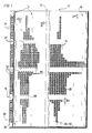
- the sieve shown in Figures 1 to 3 has a sieve wall 10 made of a metal sheet which has been bent into a circular cylinder; this sieve is intended for pressure sorters in which the fiber suspension to be sorted is introduced into the interior of the sieve cylinder formed by the sieve wall 10 and which have a rotor whose axis of rotation coincides with the axis 12 of the sieve cylinder.
- a pressure sorter is e.g. B. described and shown in EP-0042742-B.
- the fiber suspension to be sorted Since the fiber suspension to be sorted is usually fed to the sieve from above and since the rotor circulates the fiber suspension to be sorted on the inlet side of the sieve, the fiber suspension to be sorted moves helically from top to bottom along the inlet side of the sieve wall 10, which was indicated by the arrow "v" in FIG. 1.
- the inlet side of the screen was designated 14, the outlet side 16.
- the direction in which the fiber suspension passes the sieve was marked with the arrow "D" in FIGS. 1 to 4.
- 10 sieve opening channels 20 are incorporated into the sieve wall, which in the preferred embodiment shown consist of a cylindrical bore 20.
- the screen opening channels 20 are, as can clearly be seen in FIG. 1, in the sieve wall 10 according to the invention arranged in groups, each group forming a series of sieve opening channels 20 lying one behind the other in the direction of the axis 12.
- a first recess 22 is milled into the inlet side 14 of the screen wall 10, all of these recesses being approximately boat-shaped in plan view, having a triangular cross section and thus forming a groove, the width of which was designated B1.
- all of these grooves run parallel to one another and parallel to the screen cylinder axis 12.
- a recess 24 is incorporated into the screen outlet side 16 of the screen wall for each screen opening channel 20, which according to the invention is composed of a conical bore 24a and a flat-conical countersink 24b, both of which widen in the flow direction D.
- the width or the diameter of the recesses 24, namely the width B2, according to the invention is equal to or greater than the width B1.
- the thickness of the sieve wall 10 is approximately 8 mm, the grooves 22 are only 1 mm deep, and the length of the sieve opening channels 20, measured in the flow direction D, is only approximately 0.5 mm, so that the depth of the Recesses 24 and 24a, 24b is approximately 6.5 mm.
- the axes 28 of the recesses 24 on the outlet side and the axes 30 of the sieve opening channels 20 lie in the central plane 26 of the recesses 22 on the inlet side, ie in this embodiment there is no offset of the recesses and the sieve opening channels in the direction of rotation "R. "of the rotor, not shown, is provided.
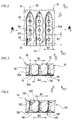
- the second embodiment shown in FIG. 4 differs from the first embodiment.
- FIG. 4 the screen wall with 110, the inlet side with 114 and the outlet side with 116, the likewise boat-shaped, inlet-side recesses with 122 and the combination of conical bores and flat-tapered recesses with outlet-side recesses with 124, which connect the recesses with each other Sieve opening channels with 120, their axes with 130, the center planes of the inlet-side recesses with 126 and the axes of the outlet
- the center planes 126 of the inlet-side recesses 122 in the direction of rotation "R" of the rotor, not shown, is offset from the axes 130 of the screen opening channels 120, while the axes 128 of the outlet-side recesses 124 coincide with the axes 130 of the screen opening channels 120.
- the offset of the recesses 122 on the inlet side, as shown in FIG. 4, is selected such that the side wall of the groove-shaped recesses 122, which increases in the direction of rotation “R” of the rotor, not shown, begins only behind the sieve opening channels 120.
- the recesses 22 and 122 on the inlet side can be machined in a simple manner by means of a profile milling cutter into the sheet forming the screen wall 10 and 110, without the strength of the screen wall being reduced too much.
Abstract
Description
Die Erfindung betrifft ein Sieb für Drucksortierer für Fasersuspensionen, welche einen insbesondere einer Einlapseite des Siebs benachbarten Rotor zur Erzeugung positiver und negativer Druckstöße in der Fasersuspensionen aufweisen, wobei das Sieb eine zu einer Siebachse rotationssymmetrische Gestalt aufweist.The invention relates to a screen for pressure sorters for fiber suspensions, which have a rotor which is in particular adjacent to a lapping side of the screen for generating positive and negative pressure surges in the fiber suspensions, the screen having a shape which is rotationally symmetrical with respect to a screen axis.
Bei der Aufbereitung von Fasersuspensionen werden in der Regel mehrere derartige Drucksortierer hintereinandergeschaltet, wobei die Sieböffnungen der hintereinandergeschalteten Drucksortierer immer kleiner werden, d.h. die Sieböffnungen der einem ersten Drucksortierer nachgeschalteten Drucksortierer sind immer kleiner als die Sieböffnungen des vorausgehenden Drucksortierers. Auf diese Weise werden Verunreinigungen und Faserzusammenballungen in Abhängigkeit von ihrer Größe stufenweise von den brauchbaren Fasern abgetrennt, da jedem Drucksortierer der sogenannte Gutstoff des vorausgehenden Drucksortierers zugeführt wird (beim Gutstoff handelt es sich um denjenigen Teil der Fasersuspension, der die Sieböffnungen eines Drucksortierers passiert hat).When processing fiber suspensions, several pressure sorters of this type are generally connected in series, the sieve openings of the pressure sorters connected in series becoming ever smaller, ie the sieve openings of the pressure sorters connected downstream of a first pressure sorter are always smaller than the sieve openings of the preceding pressure sorter. In this way, depending on their size, contamination and fiber agglomerations are gradually separated from the usable fibers, since the so-called good substance of the previous pressure sorter is fed to each pressure sorter (the good substance is the part of the fiber suspension that has passed through the screen openings of a pressure sorter) .
Von der Papierindustrie werden Geräte immer größerer Leistung gefordert; dies bedeutet für Drucksortierer, daß nicht nur eine immer höhere spezifische Durchsatzleistung gefordert wird (Menge der Fasersuspension, welche pro Zeiteinheit eine Siebfläche bestimmter Größe passiert), sondern daß eine bestimmte Sortierfeinheit mit immer weniger hintereinandergeschalteten Drucksortierern erreichbar sein soll, was sich nur mit relativ feinen Sieböffnungen erreichen läßt, welche jedoch der Erhöhung der Durchsatzleistung entgegenstehen.Devices of ever increasing performance are required by the paper industry; For pressure sorters, this means that not only is an ever higher specific throughput required (amount of fiber suspension which passes through a sieve area of a certain size per unit time), but that a certain sorting fineness should be achievable with fewer and fewer pressure sorters connected in series, which is only possible with relatively fine ones Screen openings can be reached, which, however, oppose the increase in throughput.
Zur Erhöhung der Durchsatzleistung wurden deshalb nicht nur neue Rotorformen entwickelt, sondern es wurde auch die Umfangsgeschwindigkeit der der Einlaßseite des Siebs benachbarten Rotorbereiche gesteigert, um in der Fasersuspension relativ hohe positive und negative Druckstöße und Turbulenzen zu erzeugen - durch die Druckstöpe soll ein Zusetzen der Sieböffnungen durch in der Fasersuspension enthaltene Verunreinigungen verhindert werden (an den Sieböffnungen treten Rückspüleffekte auf), und durch die Turbulenzen soll verhindert werden, daß die Fasern an der Einlapseite des Siebs eine Art Faservlies bilden, welches die Durchsatzleistung verringert oder ein Hindurchtreten brauchbarer Fasern durch die Sieböffnungen ganz verhindert. Die Maßnahmen zur Erhöhung der Durchsatzleistung (Erhöhung der Rotordrehzahl bzw. der Rotorumfangsgeschwindigkeit, aber auch Erhöhung der am Sieb auftretenden Druckdifferenz) führen jedoch dazu, daß die auf das Sieb einwirkenden Kräfte immer größer werden und sie bewirken oft eine rasche Zerstörung des Siebs, insbesondere infolge von im Siebblech auftretenden Rissen. Zur Erreichung höherer Standzeiten, d.h. zur Erzielung widerstandsfähigerer Siebe, hat man deshalb die Wandstärke der Siebe vergrößert; durch diese Maßnahme verlängern sich aber auch die von den Sieböffnungen gebildeten Durchflußkanäle, eine Folge, die sich negativ auf die Durchsatzleistung des Drucksortierers auswirkt. Des weiteren hat die Forderung nach immer leistungsfähigeren Geräten nicht nur dazu geführt, daß ein Drucksortierer pro Stunde immer gröpere Fasersuspensionsmengen verarbeiten soll, sondern daß er auch Fasersuspensionen höherer Stoffdichte (Faseranteil je Volumeneinheit) verarbeiten soll, und vor allem bei Fasersuspensionen relativ hoher Stoffdichte führen verhältnismäpiß lange Sieböffnungskanäle zu hohen Druckverlusten zwischen Einlaß- und Auslaßseite des Siebs, welche wiederum ein rasches Verstopfen der Sieböffnungen zur Folge haben.To increase the throughput, not only were new rotor shapes developed, but the circumferential speed of the rotor areas adjacent to the inlet side of the sieve was also increased in order to generate relatively high positive and negative pressure surges and turbulence in the fiber suspension - the pressure openings meant that the sieve openings were clogged are prevented by impurities contained in the fiber suspension (backwash effects occur at the sieve openings), and the turbulence is intended to prevent the fibers on the lapping side of the sieve from forming a type of fiber fleece which reduces the throughput or prevents useful fibers from passing through the sieve openings completely prevented. However, the measures for increasing the throughput (increasing the rotor speed or the peripheral speed of the rotor, but also increasing the pressure difference occurring on the sieve) mean that the forces acting on the sieve become ever greater and often cause the sieve to be destroyed rapidly, particularly as a result of cracks occurring in the screen plate. In order to achieve a longer service life, ie to achieve more resistant screens, the wall thickness of the Sieves enlarged; this measure also lengthens the flow channels formed by the sieve openings, a consequence which has a negative effect on the throughput of the pressure sorter. Furthermore, the demand for ever more powerful devices has not only led to a pressure sorter processing larger and larger amounts of fiber suspension per hour, but also processing fiber suspensions with a higher consistency (fiber content per unit volume), and especially with fiber suspensions having a relatively high consistency Long sieve opening channels lead to high pressure losses between the inlet and outlet side of the sieve, which in turn quickly clog the sieve openings.
Es sind nun schon die vielfältigsten Vorschläge für die Gestaltung der Siebwand solcher Siebe gemacht worden:The most varied suggestions for the design of the screen wall of such screens have now been made:
In der US-PS 3,581,903 der Anmelderin wurde vorgeschlagen, bei einem Sieb mit schlitzförmigen Sieböffnungskanälen in die Auslaßseite der Siebwand für jede Sieböffnung eine schiffchenförmige Ausnehmung einzufräsen und ein solches Sieb in einen Drucksortierer einzubauen, bei dem der Rotor der Auslaßseite des Siebs benachbart umläuft. Durch diese Maßnahme wird zwar die Gefahr eines Verstopfens der Sieb-Öffnungen durch in der Fasersuspension enthaltene Verunreinigungen erheblich vermindert, bei solchen Drucksortierern besteht jedoch die Gefahr, daß sich in der zu sortierenden Fasersuspension auf der Einlapseite des Siebs ein Faservlies oder dergleichen ausbildet, welches die Durchsatzleistung drastisch vermindert.In the applicant's US Pat. No. 3,581,903, it was proposed to mill a boat-shaped recess for each sieve opening in a sieve with slot-shaped sieve opening channels in the outlet side of the sieve wall and to install such a sieve in a pressure sorter in which the rotor rotates adjacent to the outlet side of the sieve. Although this measure considerably reduces the risk of the sieve openings becoming blocked by impurities contained in the fiber suspension, there is a risk with such pressure sorters that a fiber fleece or the like is formed in the fiber suspension to be sorted on the inlet side of the sieve, which forms the Throughput drastically reduced.
In der DE-AS 27 50 499 wird ein Sieb für Drucksortierer vorgeschlagen, welches aus in Richtung der Siebachse aufeinandergeschichteten ringförmigen Segmenten zusammengesetzt ist, deren jedes einen Kranz schlitzförmiger Sieböffnungskanäle aufweist und von denen jeweils zwei einander benachbarte Segmente Kränze von Ausnehmungen definieren, die sich von der Einlap- bzw. der Auslapseite des Siebs bis zu den Sieböffnungskanälen erstrecken und sich auf die letzteren zu verjüngen. Ein solches Sieb besitzt zwar in Durchstömrichtung relativ kurze Sieböffnungskanäle und es ist außerordentlich widerstandsfähig gegen hohe, von einem Rotor erzeugte Druckstöße, es ist jedoch in der Herstellung außerordentlich aufwendig und kann das Entstehen eines Faservlieses auf der Einlaßseite des Siebs nicht besonders wirksam verhindern.In DE-AS 27 50 499 a sieve for pressure sorters is proposed, which is composed of annular segments stacked one on top of the other in the direction of the sieve axis, each of which has a ring of slit-shaped sieve opening channels and of which two adjacent segments each define rings of recesses that differ from one another the inlet or the outlet side of the sieve extend to the sieve opening channels and taper towards the latter. Although such a sieve has relatively short sieve opening channels in the flow direction and it is extremely resistant to high pressure surges generated by a rotor, it is extremely complex to manufacture and cannot particularly effectively prevent the formation of a nonwoven fabric on the inlet side of the sieve.
Ähnliches gilt für das in der EP-0 093 187-B der Anmelderin offenbarte Sieb; dieses ist auf der Einlaßseite mit in Siebumfangsrichtung um das ganze Sieb herum verlaufenden Nuten und auf der Siebauslaßseite mit gefrästen, kreiszylindrischen Ausnehmungen versehen, deren Zentren in den Schnittpunkten eines von gleichseitigen Dreiecken gebildeten Netzes liegen und deren Bodenflächen vom Grund der Nuten durchbrochen werden. Der Sinn dieser Siebgestaltung ist im wesentlichen derselbe wie bei dem Sieb nach der vorstehend diskutierten US-PS 3,581,903, d.h. durch die kreiszylindrischen Ausnehmungen werden die von den Sieböffnungen gebildeten Durchflußkanäle in Durchströmrichtung erweitert. Auf der anderen Seite läßt sich auch bei dieser Siebgestaltung das Entstehen eines Faservlieses auf der Einlapseite nicht besonders wirksam verhindern.The same applies to the sieve disclosed in the applicant's EP-0 093 187-B; This is provided on the inlet side with grooves running around the entire sieve in the circumferential direction of the sieve and on the sieve outlet side with milled, circular-cylindrical recesses, the centers of which lie at the intersections of a network formed by equilateral triangles and the bottom surfaces of which are penetrated by the bottom of the grooves. The purpose of this sieve design is essentially the same as that of the sieve according to US Pat. No. 3,581,903 discussed above, that is to say the flow channels formed by the sieve openings are expanded in the flow direction by the circular cylindrical recesses. On the other hand, the formation of a nonwoven fabric on the lapping side cannot be prevented particularly effectively even with this sieve design.
Aus der EP-0042742-B ist ein Sieb für Drucksortierer bekannt geworden, welche einen einer Einlapseite des Siebs benachbarten Rotor aufweisen, wobei das Sieb eine zu einer Siebachse rotationssymmetrische Gestalt aufweist und die über ihre Wandstärke einstückige Siebwand mit die Siebeinlaßseite mit der Siebauslaßseite verbindenden Sieböffnungskanälen sowie an ihrer Einlaßseite mit Ausnehmungen versehen ist, in die die Sieböffnungskanäle münden. Bei einer ersten Ausführungsform des bekannten Siebs haben die Sieböffnungskanäle die Gestalt von sich quer zur Siebumfangsrichtung erstreckenden Schlitzen und die einlaßseitigen Ausnehmungen die Form von schiffchenförmigen Ausnehmungen, die in das Siebblech hineingefräst sind und ebenfalls quer zur Siebumfangsrichtung verlaufen, wobei für jeden Sieböffnungskanal eine solche schiffchenförmige Ausnehmung vorgesehen ist (Fig. 2 bis 4 der EP-0042742-B). Bei einer zweiten Ausführungsform dieses bekannten Siebs handelt es sich bei den Sieböffnungskanälen um kreiszylindrische Bohrungen, deren jeder eine kegelstumpfförmige Ausnehmung zugeordnet ist, die in die Einlaßseite des Siebs mündet und sich zu dieser hin mit einem verhältnismäßig kleinen Öffnungswinkel erweitert (Fig. 5 und 6). Durch die einlaßseitigen Ausnehmungen soll eine Erhöhung der Durchsatzleistung des Drucksortierers erzielt werden, was darauf zurückzuführen sein soll, daß diese einlaßseitigen Ausnehmungen zusammen mit dem auf der Einlaßseite umlaufenden Rotor zu Turbulenzen führen, welche dem Entstehen eines Faservlieses auf der Einlaßseite des Siebs entgegenwirken. Bei beiden Ausführungsformen des bekannten Drucksortierers ist aber eine nicht befriedigende Durchsatzleistung festzustellen, ganz abgesehen davon, daß es recht aufwendig ist, nicht nur die einzelnen schlitzförmigen Sieböffnungskanäle, sondern auch noch für jeden einzelnen Sieböffnungskanal eine schiffchenförmige Ausnehmung zu fräsen bzw. bei der zweiten Ausführungsform auf der Siebeinlaßseite für jeden einzelnen Sieböffnungskanal eine kegelstumpfförmige Ausnehmung herzustellen.From EP-0042742-B a sieve for pressure sorters has become known which has a rotor adjacent to an inlet side of the sieve, the sieve having a shape which is rotationally symmetrical to a sieve axis and the sieve wall which is integral with its wall thickness and connects the sieve opening channels with the sieve inlet side and the sieve outlet side and is provided on its inlet side with recesses into which the sieve opening channels open. In a first embodiment of the known sieve, the sieve opening channels are in the form of slots extending transversely to the sieve circumferential direction and the inlet-side recesses are in the form of boat-shaped recesses which are milled into the sieve plate and also run transversely to the sieve circumference direction, such a boat-shaped recess for each sieve opening channel is provided (Fig. 2 to 4 of EP-0042742-B). In a second embodiment of this known sieve, the sieve opening channels are circular-cylindrical bores, each of which is assigned a truncated cone-shaped recess which opens into the inlet side of the sieve and widens towards it with a relatively small opening angle (FIGS. 5 and 6) . The inlet-side recesses are intended to increase the throughput of the pressure sorter, which should be due to the fact that these inlet-side recesses together with the rotor rotating on the inlet side lead to turbulence which counteracts the formation of a nonwoven fabric on the inlet side of the screen. In both embodiments of the known pressure sorter, however, an unsatisfactory throughput rate can be determined, quite apart from the fact that it is quite expensive not only the individual slit-shaped sieve opening channels, but also a boat-shaped recess for each individual sieve opening channel to mill or in the second embodiment to produce a truncated cone-shaped recess on the sieve inlet side for each individual sieve opening channel.
Schließlich ist aus der WO 87/03024 ein Drucksortierer mit kreiszylindrischem Sieb bekannt, bei dem die Siebeinlaßseite mit der Siebauslaßseite verbindende, als kreiszylindrische Bohrungen ausgebildete Sieböffnungskanäle in an der Siebeinlaßseite und der Siebauslaßseite vorgesehene nutförmige, zueinander parallele und quer zur Siebumfangsrichtung verlaufende Ausnehmungen münden, wodurch die Effizienz des Siebs verbessert werden soll. Durch die Maßnahmen wird zwar der Druckverlust am Sieb vermindert, weil die engen Sieböffnungskanäle - relativ zur Siebwandstärke - verhältnismäßig kurz sind, die bekannte Siebkonstruktion hat jedoch einen gravierenden Nachteil: Die nutförmigen, sich quer zur Siebumfangsrichtung erstreckenden einlaß- und auslaßseitigen Ausnehmungen führen zur Bildung von Schwächungslinien der Siebwand, die parallel zur Siebzylinderachse und damit zu den Mantellinien des Siebzylinders verlaufen, so daß es nicht nur problematisch ist, aus einem fertig bearbeiteten Siebblech durch Biegen einen absolut rotationssymmetrischen Siebzylinder herzustellen, sondern diese Schwächungslinien führen auch zu dem Risiko von Dauerbrüchen der Siebwand aufgrund der von einem Rotor erzeugten Druckstöße.Finally, WO 87/03024 discloses a pressure sorter with a circular-cylindrical sieve, in which the sieve inlet side connects to the sieve outlet side and is formed as circular cylindrical bores in the sieve opening channels provided in the groove-shaped recesses provided on the sieve inlet side and the sieve outlet side, which are parallel to one another and run transversely to the sieve circumferential direction, as a result of which the efficiency of the sieve is to be improved. Although the measures reduce the pressure loss on the sieve because the narrow sieve opening channels - relative to the sieve wall thickness - are relatively short, the known sieve construction has a serious disadvantage: the groove-shaped recesses on the inlet and outlet sides extending transversely to the sieve circumference lead to the formation of Lines of weakness of the screen wall that run parallel to the axis of the screen cylinder and thus to the surface lines of the screen cylinder, so that it is not only problematic to produce an absolutely rotationally symmetrical screen cylinder from a finished screen plate by bending, but these lines of weakness also lead to the risk of permanent breaks of the screen wall due to the pressure surges generated by a rotor.
Der Erfindung lag nun die Aufgabe zugrunde, ein dauerhaftes, d. h. ein eine hohe Standfestigkeit aufweisendes Sieb für mit einem Rotor versehene Drucksortierer zu schaffen, welches sich relativ einfach herstellen und mit dem sich eine spezifisch hohe Durchsatzleistung erzielen läßt.The invention was based on the object, a permanent, d. H. to create a screen with a high level of stability for a pressure screen provided with a rotor, which screen is relatively easy to manufacture and with which a specifically high throughput can be achieved.
Ausgehend von einem Sieb für Drucksortierer, welche einen insbesondere einer Einlaßseite des Siebs benachbarten Rotor zur Erzeugung positiver und negativer Druckstöpe in der Fasersuspension aufweisen, wobei das Sieb eine zu einer Siebachse rotationssymmetrische Gestalt aufweist und die über ihre Wandstärke einstückige Siebwand sowohl an ihrer Einlaß- als auch an ihrer Auslaßseite mit Ausnehmungen versehen ist, welche durch Sieböffnungskanäle miteinander verbunden sind, wobei sich jede der einlaßseitigen Ausnehmungen über mehrere Sieböffnungskanäle erstreckt und als quer zur Siebumfangsrichtung verlaufende Nut ausgebildet ist und wobei die größte Breite der auslaßseitigen Ausnehmungen, gemessen in der auslaßseitigen Siebwandoberfläche, mindestens so groß ist, wie die gröpte Breite der einlaßseitigen Nuten, läßt sich diese Aufgabe erfindungsgemäß durch eine solche Siebgestaltung lösen, daß sich jede der auslaßseitigen Ausnehmungen nur über jeweils einen der Sieböffnungskanäle erstreckt. Im Falle schlitzförmiger Sieböffnungskanäle können die auslaßseitigen Ausnehmungen insbesondere so ausgebildet sein, wie dies die US-PS 3 581 903 zeigt, d. h. es kann sich um schiffchenförmige Ausnehmungen handeln. Bevorzugt werden jedoch Ausführungsformen, bei denen die Sieböffnungskanäle Bohrungen sind und die auslaßseitigen Ausnehmungen die Gestalt kegelstumpfförmiger, insbesondere flachkegeliger Ansenkungen aufweisen.Starting from a screen for pressure sorters, which one in particular have an adjacent rotor on the inlet side of the sieve for producing positive and negative pressure blocks in the fiber suspension, the sieve having a shape which is rotationally symmetrical with respect to a sieve axis and the sieve wall, which is integral over its wall thickness, is provided with recesses both on its inlet and on its outlet side, which are connected to one another by sieve opening channels, each of the inlet-side recesses extending over a plurality of sieve opening channels and being designed as a groove running transversely to the sieve circumferential direction, and the greatest width of the outlet-side recesses, measured in the outlet-side surface of the sieve wall, being at least as large as the largest width of the grooves on the inlet side, this object can be achieved according to the invention by designing a sieve such that each of the recesses on the outlet side extends only over one of the sieve opening channels. In the case of slot-shaped sieve opening channels, the recesses on the outlet side can in particular be designed as shown in US Pat. No. 3,581,903, ie they can be boat-shaped recesses. However, embodiments are preferred in which the sieve opening channels are bores and the recesses on the outlet side have the shape of frustoconical, in particular flat-conical, countersinks.
Die sowohl an der Einlaß- als auch an der Auslaßseite des Siebs vorgesehenen Ausnehmungen erlauben es, für die Herstellung erfindungsgemäßer Siebe verhältnismäßig dicke Bleche zu verwenden, ohne daß relativ enge bzw. feine Sieböffnungskanäle zu hohen Druckverlusten am Sieb führen und einer hohen Durchsatzleistung des Drucksortierers entgegenstehen, da durch die beiderseits vorgesehenen Ausnehmungen die Länge der Sieböffnungskanäle beträchtlich vermindert wird. Im Gegensatz zu dem aus der EP-0042742-B bekannten Sieb muß auch nicht für jeden Sieböffnungskanal eine gesonderte einlaßseitige Ausnehmung hergestellt werden. In Verbindung mit einem an der Einlaßseite des Siebs umlaufenden Rotor führen die auf der Einlaßseite vorgesehenen nutförmigen Ausnehmungen zu den gewünschten Turbulenzen in der zu sortierenden Fasersuspension, wodurch der Gefahr der Bildung von Faseransammlungen an der Siebeinlaßseite wirksam begegnet wird. Die verhältnismäßig großen auslaßseitigen Ausnehmungen führen in Verbindung mit den vom Rotor erzeugten negativen Druckstößen zu einem kräftigen Rückspüleffekt, so daß die Sieböffnungskanäle nicht verstopft werden können. Durch die sich nur über jeweils einen Sieböffnungskanal erstreckenden auslaßseitigen Ausnehmungen wird schließlich die Bildung von Schwächungslinien in der Siebwand vermieden, vor allem dann, wenn die Sieböffnungskanäle nicht schlitzförmig ausgebildet sind und die auslaßseitigen Ausnehmungen die Form von Ansenkungen haben.The recesses provided both on the inlet and on the outlet side of the sieve allow relatively thick sheets to be used for the production of sieves according to the invention, without relatively narrow or fine sieve opening channels leading to high pressure losses on the sieve and opposing a high throughput of the pressure sorter , because the length of the sieve opening channels is considerable due to the recesses provided on both sides is reduced. In contrast to the sieve known from EP-0042742-B, it is also not necessary to produce a separate inlet-side recess for each sieve opening channel. In conjunction with a rotor rotating on the inlet side of the sieve, the groove-shaped recesses provided on the inlet side lead to the desired turbulence in the fiber suspension to be sorted, as a result of which the risk of formation of fibers on the sieve inlet side is effectively countered. The relatively large recesses on the outlet side, in conjunction with the negative pressure surges generated by the rotor, lead to a powerful backwashing effect, so that the sieve opening channels cannot be blocked. The outlet-side recesses, which only extend over one sieve opening channel in each case, ultimately prevent the formation of lines of weakness in the sieve wall, especially if the sieve opening channels are not slit-shaped and the outlet-side recesses have the form of countersinks.
Besonders bevorzugt werden Ausführungsformen, bei denen die einlapseitigen Nuten flach, insbesondere maximal ungefähr 1 mm tief sind, da Nuten einer solchen Tiefe für die Erzeugung der gewünschten Turbulenzen ausreichen und die Siebwand nicht nennenswert schwächen. Hingegen empfiehlt sich für die auslaßseitigen Ausnehmungen eine verhältnismäßig große Tiefe von mehr als der Hälfte der Dicke der Siebwand; da jedem Sieböffnungskanal eine gesonderte auslaßseitige Ausnehmung zugeordnet ist, schwächen diese Ausnehmungen trotz ihrer relativ großen Tiefe die Siebwand nicht in unzulässiger Weise, obwohl sie zu den angestrebten kurzen Sieböffnungskanälen führen. Besonders vorteilhaft sind Verhältnisse, wie sie in den beigefügten Ansprüchen 5 bis 8 näher angegeben sind.Embodiments are particularly preferred in which the flaps on the flap side are flat, in particular a maximum of approximately 1 mm deep, since grooves of such a depth are sufficient to generate the desired turbulence and do not significantly weaken the screen wall. On the other hand, a relatively large depth of more than half the thickness of the screen wall is recommended for the recesses on the outlet side; since each sieve opening channel is assigned a separate outlet-side recess, these recesses do not weaken the sieve wall in an inadmissible manner despite their relatively large depth, although they lead to the desired short sieve opening channels. Ratios as specified in the appended claims 5 to 8 are particularly advantageous.
Damit das Sieb langfaserige Verunreinigungen besser abweist, ist es schließlich empfehlenswert, die einlaßseitigen Nuten gegenüber den Achsen der Sieböffnungskanäle in Rotordrehrichtung versetzt anzuordnen; dadurch wird außerdem die Gefahr eines Verstopfens der Sieböffnungen noch weiter verringert.Finally, in order that the sieve repels long-fiber impurities better, it is advisable to arrange the grooves on the inlet side offset with respect to the axes of the sieve opening channels in the direction of rotation of the rotor; this also further reduces the risk of the screen openings becoming blocked.
Bezüglich der Dimensionierung der Ausnehmungen ist zu beachten, daß diese einerseits so groß sein sollen, daß die Strömungsgeschwindigkeit im Bereich der Ausnehmungen so gering wird, daß auch bei verhältnismäßig groper Stoffdichte die Reibungsverluste vernachläpißbar klein werden, daß aber andererseits die Siebwand durch die Ausnehmungen nicht so stark geschwächt wird, daß die erforderliche Festigkeit des Siebs nicht mehr gewährleistet wäre.With regard to the dimensioning of the recesses, it should be noted that on the one hand they should be so large that the flow velocity in the region of the recesses becomes so low that the friction losses become negligibly small even with a relatively large material density, but on the other hand the screen wall through the recesses is not so is greatly weakened that the required strength of the screen would no longer be guaranteed.
Weitere Vorteile, Merkmale und Einzelheiten der Erfindung ergeben sich aus der beigefügten zeichnerischen Darstellung und der nachfolgenden Beschreibung zweier bevorzugter Ausführungsformen des erfindungsgemäßen Siebs; in der Zeichnung zeigen:
- Fig. 1:
- Einen Schnitt längs einer Durchmesserebene durch eine erste Ausführungsform des erfindungsgemäßen Siebs, welche die Gestalt eines Kreiszylinders be- sitzt;
- Fig. 2:
- eine Ansicht eines Teils der Siebwand des Siebs gemäß Fig. 1, gesehen in Richtung des Pfeils "D" in Fig. 1 (Ansicht auf die Einlapseite des Siebs);
- Fig. 3:
- einen Schnitt nach der Linie 3-3 in Fig. 2, und
- Fig. 4:
- eine der Fig. 3 entsprechende Darstellung der zweiten Ausführungsform des erfindungsgemäßen Siebs.
- Fig. 1:
- A section along a diameter plane through a first embodiment of the sieve according to the invention, which has the shape of a circular cylinder;
- Fig. 2:
- a view of part of the screen wall of the screen of Figure 1, seen in the direction of arrow "D" in Fig. 1 (view of the inlet side of the screen).
- Fig. 3:
- a section along the line 3-3 in Fig. 2, and
- Fig. 4:
- a representation corresponding to FIG. 3 of the second embodiment of the sieve according to the invention.
Das in den Fig. 1 bis 3 gezeigte Sieb besitzt eine aus einem Metallblech hergestellte Siebwand 10, die zu einem Kreiszylinder gebogen wurde; dieses Sieb ist für Drucksortierer bestimmt, bei denen die zu sortierende Fasersuspension in das Innere des von der Siebwand 10 gebildeten Siebzylinders eingeleitet wird und welche einen Rotor aufweisen, dessen Rotationsachse mit der Achse 12 des Siebzylinders zusammenfällt. Ein derartiger Drucksortierer ist z. B. in der EP-0042742-B beschrieben und dargestellt. Da die zu sortierende Fasersuspension dem Sieb in der Regel von oben zugeführt wird und da der Rotor die zu sortierende Fasersuspension an der Einlaßseite des Siebs in Umlauf versetzt, bewegt sich die zu sortierende Fasersuspension schraubenlinienförmig von oben nach unten der Einlaßseite der Siebwand 10 entlang, was in Fig. 1 durch den Pfeil "v" angedeutet wurde. Die Einlaßseite des Siebs wurde mit 14, die Auslaßseite mit 16 bezeichnet. Die Richtung, in der die Fasersuspension das Sieb passiert, wurde in den Fig. 1 bis 4 mit dem Pfeil "D" gekennzeichnet.The sieve shown in Figures 1 to 3 has a
Wie sich aus den Fig. 1 bis 3 ergibt, sind in die Siebwand 10 Sieböffnungskanäle 20 eingearbeitet, welche bei der dargestellten bevorzugten Ausführungsform aus einer zylindrischen Bohrung 20 bestehen. Die Sieböffnungskanäle 20 sind, wie sich deutlich aus Fig. 1 ergibt, in der Siebwand 10 erfindungsgemäß in Gruppen angeordnet, wobei jede Gruppe eine Reihe von in Richtung der Achse 12 hintereinander liegenden Sieböffnungskanälen 20 bildet. Für jede dieser Gruppen ist in die Einlaßseite 14 der Siebwand 10 eine erste Ausnehmung 22 eingefräst, wobei alle diese Ausnehmungen in der Draufsicht ungefähr schiffchenförmig sind, einen dreieckigen Querschnitt besitzen und so eine Nut bilden, deren Breite mit B1 bezeichnet wurde. Außerdem verlaufen alle diese Nuten parallel zueinander und parallel zur Siebzylinderachse 12.1 to 3, 10
Erfindungsgemäß ist in die Siebauslaßseite 16 der Siebwand für jeden Sieböffnungskanal 20 eine Ausnehmung 24 eingearbeitet, die sich erfindungsgemäß aus einer konischen Bohrung 24a und einer flachkegeligen Ansenkung 24b zusammensetzt, welche sich beide in Durchströmrichtung D erweitern. An der auslaßseitigen Siebwandoberfläche ist die Breite bzw. der Durchmesser der Ausnehmungen 24, nämlich die Breite B2, erfindungsgemäß gleich oder größer als die Breite B1.According to the invention, a
Bei einem bevorzugten Sieb beträgt die Dicke der Siebwand 10 ca. 8 mm, die Nuten 22 sind nur 1 mm tief, und die Länge der Sieböffnungskanäle 20, gemessen in Durchströmrichtung D, beträgt lediglich ca. 0,5 mm, so daß die Tiefe der Ausnehmungen 24 bzw. 24a, 24b ca. 6,5 mm beträgt.In a preferred sieve, the thickness of the
Bei der Ausführungsform nach den Fig. 1 bis 3 liegen die Achsen 28 der auslaßseitigen Ausnehmungen 24 und die Achsen 30 der Sieböffnungskanäle 20 in der Mittelebene 26 der einlaßseitigen Ausnehmungen 22, d. h. bei dieser Ausführungsform ist kein Versatz der Ausnehmungen und der Sieböffnungskanäle in Drehrichtung "R" des nicht dargestellten Rotors vorgesehen.In the embodiment according to FIGS. 1 to 3, the
Diesbezüglich unterscheidet sich die zweite Ausführungsform nach Fig. 4 von der ersten Ausführungsform. In Fig. 4 sind die Siebwand mit 110, deren Einlaßseite mit 114 und deren Auslaßseite mit 116 bezeichnet, die gleichfalls schiffchenförmigen, einlaßseitigen Ausnehmungen mit 122 und die gleichfalls als Kombination konischer Bohrungen und flachkegeliger Ansenkungen ausgebildeten auslaßseitigen Ausnehmungen mit 124, die die Ausnehmungen miteinander verbindenden Sieböffnungskanäle mit 120, deren Achsen mit 130, die Mittelebenen der einlaßseitigen Ausnehmungen mit 126 und die Achsen der auslaßseitigen Ausnehmungen mit 128. Die Fig. 4 zeigt, daß bei dieser Ausführungsform nach einem weiteren Merkmal der Erfindung die Mittelebenen 126 der einlaßseitigen Ausnehmungen 122 in Drehrichtung "R" des nicht dargestellten Rotors gegenüber den Achsen 130 der Sieböffnungskanäle 120 versetzt sind, während die Achsen 128 der auslaßseitigen Ausnehmungen 124 mit den Achsen 130 der Sieböffnungskanäle 120 zusammenfallen. Der Versatz der einlaßseitigen Ausnehmungen 122 ist, wie in Fig. 4 gezeigt, so gewählt, daß die - in Drehrichtung "R" des nicht dargestellten Rotors gesehen - ansteigende Seitenwand der nutförmigen Ausnehmungen 122 erst hinter den Sieböffnungskanälen 120 beginnt.In this regard, the second embodiment shown in FIG. 4 differs from the first embodiment. In Fig. 4, the screen wall with 110, the inlet side with 114 and the outlet side with 116, the likewise boat-shaped, inlet-side recesses with 122 and the combination of conical bores and flat-tapered recesses with outlet-side recesses with 124, which connect the recesses with each other Sieve opening channels with 120, their axes with 130, the center planes of the inlet-side recesses with 126 and the axes of the outlet-side recesses with 128. FIG. 4 shows that in this embodiment, according to a further feature of the invention, the center planes 126 of the inlet-
Durch den Verlauf der nutförmigen einlaßseitigen Ausnehmungen 22 bzw. 122 quer zur Anströmgeschwindigkeit v der zu sortierenden Fasersuspension werden an der Einlapseite 14 bzw. 114 der Siebwand Turbulenzen erzeugt, die dem Verstopfen der Sieböffnungen und der Bildung eines Faservlieses auf der Siebeinlaßseite entgegenwirken. Die einlaßseitigen Ausnehmungen 22 bzw. 122 lassen sich in einfacher Weise mittels eines Profilscheibenfräsers in das die Siebwand 10 bzw. 110 bildende Blech einarbeiten, ohne daß dadurch die Festigkeit der Siebwand zu sehr verringert wird.The course of the groove-shaped
Claims (9)
- Screen for pressure sorters for fibre suspensions comprising a rotor adjacent, in particular, to an inlet side (14, 114) of the screen for generating positive and negative pressure surges in the fibre suspension, said screen having a shape rotationally symmetrical in relation to a screen axis (12), and the screen wall (10, 110) integral throughout its wall thickness being provided on both its inlet (14, 114) and outlet (16, 116) sides with recesses (22, 122, 24, 124) connected to one another by screen opening channels (20, 120), each of said recesses (22, 122) on the inlet side extending over several screen opening channels (20, 120) and being in the form of a groove extending transversely to the circumferential direction of said screen, and the largest width (B2) of said recesses (24, 124) on the outlet side, measured in the screen wall surface on the outlet side, being at least as large as the largest width (B1) of the grooves (22, 122) on the inlet side, characterized in that each of the recesses (24, 124) on the outlet side extends over only one of the screen opening channels (20, 120) respectively.
- Screen as defined in claim 1, characterized in that the grooves (122) on the inlet side are arranged in offset relation to the axes (130) of the screen opening channels (120) in the direction of rotation (R) of the rotor.
- Screen as defined in claim 1 or 2, characterized in that the recesses (24, 124) on the outlet side comprise frustoconical countersinks (24b).
- Screen as defined in claim 3, characterized in that the countersinks (24b) on the outlet side are in the form of flat tapering countersinks, the taper thereof forming at the tip in cross section an angle of at least 90°.
- Screen as defined in any or several of claims 1 to 4, characterized in that the depth of the grooves (22, 122) on the inlet side is approximately 1/10 to approximately 1/5 of the total thickness of the screen wall (10, 110).
- Screen as defined in any or several of claims 1 to 5, characterized in that the depth of the recesses (24a, 24b) on the outlet side is approximately 4/5 of the total thickness of the screen wall (10, 110).
- Screen as defined in any or several of claims 1 to 6, characterized in that the length of the screen opening channels (20, 120) measured in the flow-through direction is at the most approximately 1/10 of the total thickness of the screen wall (10, 110).
- Screen as defined in claim 7, characterized in that the length of the screen opening channels (20, 120) is approximately 5/100 to approximately 7/100 of the total thickness of the screen wall (10, 110).
- Screen as defined in any or several of the preceding claims, characterized in that the recesses (24) on the outlet side each comprise a conical bore (24a) adjoining the screen opening channel (20) and widening in the flow-through direction (D) and a countersink (24b) adjoining said bore.
Priority Applications (1)
| Application Number | Priority Date | Filing Date | Title |
|---|---|---|---|
| AT90917475T ATE96863T1 (en) | 1989-12-06 | 1990-12-05 | SCREEN FOR PRESSURE SCREENS FOR FIBER SUSPENSIONS. |
Applications Claiming Priority (2)
| Application Number | Priority Date | Filing Date | Title |
|---|---|---|---|
| DE3940334A DE3940334A1 (en) | 1989-12-06 | 1989-12-06 | SCREEN FOR PRINT SORTING FOR FIBER SUSPENSIONS |
| DE3940334 | 1989-12-06 |
Publications (2)
| Publication Number | Publication Date |
|---|---|
| EP0456788A1 EP0456788A1 (en) | 1991-11-21 |
| EP0456788B1 true EP0456788B1 (en) | 1993-11-03 |
Family
ID=6394921
Family Applications (1)
| Application Number | Title | Priority Date | Filing Date |
|---|---|---|---|
| EP90917475A Expired - Lifetime EP0456788B1 (en) | 1989-12-06 | 1990-12-05 | Sieve for a pressure sorting device for fibre suspensions |
Country Status (5)
| Country | Link |
|---|---|
| US (1) | US5259512A (en) |
| EP (1) | EP0456788B1 (en) |
| CA (1) | CA2045677C (en) |
| DE (2) | DE3940334A1 (en) |
| WO (1) | WO1991008338A1 (en) |
Families Citing this family (19)
| Publication number | Priority date | Publication date | Assignee | Title |
|---|---|---|---|---|
| AT398090B (en) * | 1992-05-15 | 1994-09-26 | Andritz Patentverwaltung | DEVICE FOR SEPARATING LIQUID FROM SOLIDS-LIQUID MIXTURES WITH A SOLIDS RETENTION DEVICE AND DEVICE IN THE FORM OF A SCREW PRESS |
| AT398088B (en) * | 1992-11-09 | 1994-09-26 | Fehrer Textilmasch | PERFORATED PLATE FOR A DEVICE FOR NEEDLING A FIBER FIBER |
| US5384044A (en) * | 1993-09-07 | 1995-01-24 | Techniweave, Inc. | Fluid separation devices and methods of making same |
| US5624560A (en) * | 1995-04-07 | 1997-04-29 | Baker Hughes Incorporated | Wire mesh filter including a protective jacket |
| US5642781A (en) * | 1994-10-07 | 1997-07-01 | Baker Hughes Incorporated | Multi-passage sand control screen |
| ATE181120T1 (en) * | 1995-02-03 | 1999-06-15 | Finckh Maschf | PRESSURE SORTER FOR SORTING FIBER SUSPENSIONS AND SCREEN FOR SUCH A PRESSURE SORTER |
| US5598890A (en) * | 1995-10-23 | 1997-02-04 | Baker Hughes Inc. | Completion assembly |
| US5611399A (en) * | 1995-11-13 | 1997-03-18 | Baker Hughes Incorporated | Screen and method of manufacturing |
| FI100010B (en) * | 1995-11-28 | 1997-08-15 | Ahlstrom Machinery Oy | The screen cylinder |
| JP3396456B2 (en) * | 2000-02-04 | 2003-04-14 | 三菱重工業株式会社 | Stock selection equipment |
| CA2403127A1 (en) * | 2000-02-19 | 2002-10-11 | Voith Finckh Fiber Systems Gmbh & Co. Kg | Sieve for fibre suspensions and a method for producing same |
| US7168570B2 (en) * | 2001-10-24 | 2007-01-30 | Advanced Fiber Technologies | Screen cylinder with performance boosting configuration |
| FI118810B (en) * | 2003-09-01 | 2008-03-31 | Anpap Oy | Screening structure for use in the manufacture of a fiber product |
| SE526033C3 (en) | 2003-11-06 | 2009-12-08 | Metso Paper Inc | Screening device and strainer for screening of pulp suspensions |
| US7306176B1 (en) | 2004-06-21 | 2007-12-11 | Prince Industries, Inc. | Compression assembly |
| CN101291738B (en) * | 2005-10-19 | 2011-03-09 | 株式会社荒井铁工所 | Filter member |
| SE537441C2 (en) * | 2013-08-29 | 2015-04-28 | Bomill Ab | Drum, a machine incorporating such a drum, and a method of manufacturing such a drum |
| DE102016110271A1 (en) * | 2015-07-10 | 2017-01-12 | Hilite Germany Gmbh | Screen for a hydraulic valve and hydraulic valve |
| CN113512897B (en) * | 2021-06-24 | 2022-09-09 | 广东冠豪新材料研发有限公司 | Full bamboo pulp natural color kraft paper reinforced interweaving force processing equipment |
Family Cites Families (12)
| Publication number | Priority date | Publication date | Assignee | Title |
|---|---|---|---|---|
| DE1157200B (en) * | 1962-02-08 | 1963-11-14 | Buckau Wolf Maschf R | Sieve for separating solids from a solid-liquid mixture |
| DE1905832U (en) * | 1964-09-16 | 1964-12-03 | Hermann Finckh G M B H | SECURE FOR PAPER FABRIC SUSPENSIONS. |
| DE2750499C3 (en) * | 1977-11-11 | 1982-02-04 | Hermann Finckh, Maschinenfabrik GmbH & Co, 7417 Pfullingen | Sorter for fiber suspension |
| US4276159A (en) * | 1980-06-19 | 1981-06-30 | The Black Clawson Company | Apparatus for screening paper fiber stock |
| EP0093187B2 (en) * | 1982-05-04 | 1990-02-28 | Hermann Finckh Maschinenfabrik GmbH & Co. | Screen drum for a pulp stock screening apparatus |
| FI67588C (en) * | 1983-01-26 | 1985-04-10 | Ahlstroem Oy | SILPLAOT |
| US4717471A (en) * | 1985-09-05 | 1988-01-05 | The Black Clawson Company | Apparatus for screening paper fiber stock |
| SE450711B (en) * | 1985-11-14 | 1987-07-20 | Besam Ag | screening member |
| ATE43661T1 (en) * | 1986-07-15 | 1989-06-15 | Finckh Maschf | PRINT SORTER. |
| FR2613389A1 (en) * | 1987-04-06 | 1988-10-07 | Lamort E & M | IMPROVEMENT IN SIEVES FOR PULP CLEANERS |
| FI77279C (en) * | 1987-04-30 | 1989-02-10 | Ahlstroem Oy | FOERFARANDE OCH ANORDNING FOER BEHANDLING AV FIBERSUSPENSION. |
| US4986900A (en) * | 1989-04-04 | 1991-01-22 | A. Ahlstrom Corporation | Sectional screen cylinder |
-
1989
- 1989-12-06 DE DE3940334A patent/DE3940334A1/en not_active Withdrawn
-
1990
- 1990-12-05 US US07/743,344 patent/US5259512A/en not_active Expired - Fee Related
- 1990-12-05 CA CA002045677A patent/CA2045677C/en not_active Expired - Fee Related
- 1990-12-05 DE DE90917475T patent/DE59003364D1/en not_active Expired - Fee Related
- 1990-12-05 EP EP90917475A patent/EP0456788B1/en not_active Expired - Lifetime
- 1990-12-05 WO PCT/DE1990/000942 patent/WO1991008338A1/en active IP Right Grant
Also Published As
| Publication number | Publication date |
|---|---|
| CA2045677C (en) | 2001-08-21 |
| CA2045677A1 (en) | 1991-06-07 |
| EP0456788A1 (en) | 1991-11-21 |
| DE59003364D1 (en) | 1993-12-09 |
| US5259512A (en) | 1993-11-09 |
| WO1991008338A1 (en) | 1991-06-13 |
| DE3940334A1 (en) | 1991-06-13 |
Similar Documents
| Publication | Publication Date | Title |
|---|---|---|
| EP0456788B1 (en) | Sieve for a pressure sorting device for fibre suspensions | |
| DE3400423C3 (en) | Use of a perforated plate over which a fiber suspension can flow for classification | |
| DE102007020325B3 (en) | Process for producing a screen for the treatment of pulp suspensions suitable for paper production | |
| DE2522349A1 (en) | FINE MILL FOR WOOD SANDING LOW CONSISTENCY | |
| DE4000248C2 (en) | ||
| EP2516733A1 (en) | Method and screening device for screening a fiber suspension | |
| EP0146641B1 (en) | Sorting screen for fibrous suspensions | |
| EP1895046B1 (en) | Pulper with screen plate having maximum defibering edges | |
| DE19911884A1 (en) | Pressure sorter for screening a paper pulp suspension and screen clearer for one | |
| AT395325B (en) | DEVICE FOR SEPARATING A CELLULOSE-FIBER-MIXED SUSPENSION | |
| EP0093187B1 (en) | Screen drum for a pulp stock screening apparatus | |
| EP0805890B1 (en) | Fibre suspension pressure sorting machine and sieve for such pressure sorting machines | |
| DE3015370C2 (en) | Screen basket for sorters in the paper industry | |
| DE4432842C2 (en) | Process for discharging unwanted solid particles from an aqueous fiber suspension and device for carrying it out | |
| DE202016008505U1 (en) | pulper | |
| EP0807709B1 (en) | Apparatus for screening a fibrous suspension | |
| EP0905309B1 (en) | Screen and pressure screening device for fibre suspensions | |
| DE60028188T2 (en) | screening device | |
| DE3448571C2 (en) | Pulp screen drum | |
| DE19747653C2 (en) | Sieve for fiber suspensions | |
| DE256236C (en) | ||
| DE7533355U (en) | CENTRIFUGAL SEPARATOR DEVICE WITH AT LEAST TWO CENTRIFUGAL SEPARATORS | |
| DE19916038A1 (en) | Process for wet screening of fiber suspensions in pressure sorters and pressure sorter screens | |
| DE19712301C2 (en) | Unpressurized sorter for sorting pulp suspensions | |
| DE202007014091U1 (en) | Sieve, in particular rigid sieve for the treatment of papermaking pulp suspensions |
Legal Events
| Date | Code | Title | Description |
|---|---|---|---|
| PUAI | Public reference made under article 153(3) epc to a published international application that has entered the european phase |
Free format text: ORIGINAL CODE: 0009012 |
|
| 17P | Request for examination filed |
Effective date: 19910806 |
|
| AK | Designated contracting states |
Kind code of ref document: A1 Designated state(s): AT DE FR GB IT NL SE |
|
| 17Q | First examination report despatched |
Effective date: 19930414 |
|
| GRAA | (expected) grant |
Free format text: ORIGINAL CODE: 0009210 |
|
| AK | Designated contracting states |
Kind code of ref document: B1 Designated state(s): AT DE FR GB IT NL SE |
|
| PG25 | Lapsed in a contracting state [announced via postgrant information from national office to epo] |
Ref country code: SE Effective date: 19931103 |
|
| REF | Corresponds to: |
Ref document number: 96863 Country of ref document: AT Date of ref document: 19931115 Kind code of ref document: T |
|
| ITF | It: translation for a ep patent filed |
Owner name: BARZANO' E ZANARDO MILA |
|
| REF | Corresponds to: |
Ref document number: 59003364 Country of ref document: DE Date of ref document: 19931209 |
|
| ET | Fr: translation filed | ||
| GBT | Gb: translation of ep patent filed (gb section 77(6)(a)/1977) |
Effective date: 19940126 |
|
| PLBE | No opposition filed within time limit |
Free format text: ORIGINAL CODE: 0009261 |
|
| STAA | Information on the status of an ep patent application or granted ep patent |
Free format text: STATUS: NO OPPOSITION FILED WITHIN TIME LIMIT |
|
| 26N | No opposition filed | ||
| REG | Reference to a national code |
Ref country code: GB Ref legal event code: IF02 |
|
| PGFP | Annual fee paid to national office [announced via postgrant information from national office to epo] |
Ref country code: FR Payment date: 20020927 Year of fee payment: 13 |
|
| PGFP | Annual fee paid to national office [announced via postgrant information from national office to epo] |
Ref country code: GB Payment date: 20021204 Year of fee payment: 13 Ref country code: AT Payment date: 20021204 Year of fee payment: 13 |
|
| PGFP | Annual fee paid to national office [announced via postgrant information from national office to epo] |
Ref country code: NL Payment date: 20021223 Year of fee payment: 13 |
|
| PGFP | Annual fee paid to national office [announced via postgrant information from national office to epo] |
Ref country code: DE Payment date: 20021230 Year of fee payment: 13 |
|
| PG25 | Lapsed in a contracting state [announced via postgrant information from national office to epo] |
Ref country code: GB Free format text: LAPSE BECAUSE OF NON-PAYMENT OF DUE FEES Effective date: 20031205 Ref country code: AT Free format text: LAPSE BECAUSE OF NON-PAYMENT OF DUE FEES Effective date: 20031205 |
|
| PG25 | Lapsed in a contracting state [announced via postgrant information from national office to epo] |
Ref country code: NL Free format text: LAPSE BECAUSE OF NON-PAYMENT OF DUE FEES Effective date: 20040701 Ref country code: DE Free format text: LAPSE BECAUSE OF NON-PAYMENT OF DUE FEES Effective date: 20040701 |
|
| GBPC | Gb: european patent ceased through non-payment of renewal fee |
Effective date: 20031205 |
|
| PG25 | Lapsed in a contracting state [announced via postgrant information from national office to epo] |
Ref country code: FR Free format text: LAPSE BECAUSE OF NON-PAYMENT OF DUE FEES Effective date: 20040831 |
|
| NLV4 | Nl: lapsed or anulled due to non-payment of the annual fee |
Effective date: 20040701 |
|
| REG | Reference to a national code |
Ref country code: FR Ref legal event code: ST |
|
| PG25 | Lapsed in a contracting state [announced via postgrant information from national office to epo] |
Ref country code: IT Free format text: LAPSE BECAUSE OF NON-PAYMENT OF DUE FEES;WARNING: LAPSES OF ITALIAN PATENTS WITH EFFECTIVE DATE BEFORE 2007 MAY HAVE OCCURRED AT ANY TIME BEFORE 2007. THE CORRECT EFFECTIVE DATE MAY BE DIFFERENT FROM THE ONE RECORDED. Effective date: 20051205 |