EP0456643B1 - Adjustable cooking oven - Google Patents
Adjustable cooking oven Download PDFInfo
- Publication number
- EP0456643B1 EP0456643B1 EP90901475A EP90901475A EP0456643B1 EP 0456643 B1 EP0456643 B1 EP 0456643B1 EP 90901475 A EP90901475 A EP 90901475A EP 90901475 A EP90901475 A EP 90901475A EP 0456643 B1 EP0456643 B1 EP 0456643B1
- Authority
- EP
- European Patent Office
- Prior art keywords
- oven
- cooking
- hood
- accordance
- duct
- Prior art date
- Legal status (The legal status is an assumption and is not a legal conclusion. Google has not performed a legal analysis and makes no representation as to the accuracy of the status listed.)
- Expired - Lifetime
Links
- 238000010411 cooking Methods 0.000 title claims abstract description 270
- 235000013305 food Nutrition 0.000 claims abstract description 126
- 238000000034 method Methods 0.000 claims abstract description 17
- 230000008569 process Effects 0.000 claims abstract description 11
- 238000005457 optimization Methods 0.000 claims abstract description 7
- 238000004140 cleaning Methods 0.000 claims description 21
- XLYOFNOQVPJJNP-UHFFFAOYSA-N water Substances O XLYOFNOQVPJJNP-UHFFFAOYSA-N 0.000 claims description 14
- 238000013016 damping Methods 0.000 claims description 10
- 238000010438 heat treatment Methods 0.000 claims description 9
- 238000012423 maintenance Methods 0.000 claims description 6
- 239000000203 mixture Substances 0.000 claims description 5
- 238000004891 communication Methods 0.000 claims description 4
- 230000003134 recirculating effect Effects 0.000 claims description 2
- 229910001220 stainless steel Inorganic materials 0.000 claims description 2
- 239000010935 stainless steel Substances 0.000 claims description 2
- 238000006073 displacement reaction Methods 0.000 claims 1
- 238000012546 transfer Methods 0.000 abstract description 4
- 238000010276 construction Methods 0.000 description 21
- 238000004880 explosion Methods 0.000 description 9
- 238000009826 distribution Methods 0.000 description 8
- 230000004913 activation Effects 0.000 description 7
- 239000002184 metal Substances 0.000 description 5
- 230000007246 mechanism Effects 0.000 description 4
- 238000007789 sealing Methods 0.000 description 4
- 230000006835 compression Effects 0.000 description 3
- 238000007906 compression Methods 0.000 description 3
- 230000008878 coupling Effects 0.000 description 3
- 238000010168 coupling process Methods 0.000 description 3
- 238000005859 coupling reaction Methods 0.000 description 3
- 238000004519 manufacturing process Methods 0.000 description 3
- 230000003020 moisturizing effect Effects 0.000 description 3
- 230000036961 partial effect Effects 0.000 description 3
- 230000002829 reductive effect Effects 0.000 description 3
- 238000010348 incorporation Methods 0.000 description 2
- 230000001939 inductive effect Effects 0.000 description 2
- 239000011810 insulating material Substances 0.000 description 2
- 238000003303 reheating Methods 0.000 description 2
- 238000000926 separation method Methods 0.000 description 2
- 230000000712 assembly Effects 0.000 description 1
- 238000000429 assembly Methods 0.000 description 1
- 238000007664 blowing Methods 0.000 description 1
- 230000008859 change Effects 0.000 description 1
- 230000008602 contraction Effects 0.000 description 1
- 238000004320 controlled atmosphere Methods 0.000 description 1
- 230000003247 decreasing effect Effects 0.000 description 1
- 238000011067 equilibration Methods 0.000 description 1
- 238000007667 floating Methods 0.000 description 1
- 238000009413 insulation Methods 0.000 description 1
- 230000000670 limiting effect Effects 0.000 description 1
- 238000002360 preparation method Methods 0.000 description 1
- 230000009467 reduction Effects 0.000 description 1
- 230000003014 reinforcing effect Effects 0.000 description 1
- 230000000717 retained effect Effects 0.000 description 1
- 238000005096 rolling process Methods 0.000 description 1
- 239000007921 spray Substances 0.000 description 1
- 238000005728 strengthening Methods 0.000 description 1
- 238000012360 testing method Methods 0.000 description 1
- 238000013022 venting Methods 0.000 description 1
- 239000002699 waste material Substances 0.000 description 1
Images




Classifications
-
- A—HUMAN NECESSITIES
- A21—BAKING; EDIBLE DOUGHS
- A21B—BAKERS' OVENS; MACHINES OR EQUIPMENT FOR BAKING
- A21B1/00—Bakers' ovens
- A21B1/02—Bakers' ovens characterised by the heating arrangements
- A21B1/24—Ovens heated by media flowing therethrough
- A21B1/26—Ovens heated by media flowing therethrough by hot air
-
- A—HUMAN NECESSITIES
- A21—BAKING; EDIBLE DOUGHS
- A21B—BAKERS' OVENS; MACHINES OR EQUIPMENT FOR BAKING
- A21B1/00—Bakers' ovens
- A21B1/42—Bakers' ovens characterised by the baking surfaces moving during the baking
- A21B1/48—Bakers' ovens characterised by the baking surfaces moving during the baking with surfaces in the form of an endless band
Definitions
- This invention relates generally to ovens and associated methods for cooking of food products or the like. More particularly, the invention is directed to an oven in which a heated gaseous cooking medium is applied to the food product while moved through the oven by a conveyor.
- Cooking ovens utilized for mass cooking of food products are well known in the art.
- a continuous oven having a heated gaseous cooking medium comprising a mixture of steam and air is made to flow over the food product while the food product moves through the oven by means of a conveyor.
- the temperature of the gaseous cooking medium may be between approximately 250° F (121 °C) and up to approximately 700° F (371 °C) for full or partial cooking. It is of course desired to make the cooking process as rapid as possible while obtaining the desired degree of cooking, browning and moisture content in the food product being cooked.
- One cooking oven as disclosed in U. S. Patent No. 4,563,945, discloses a "controlled atmosphere oven" which allows adjustability of temperature and the proportion of steam in the gaseous cooking medium to provide the desired cooking atmosphere for the particular food product and the degree of doneness desired by the food processor.
- the gaseous cooking medium being a mixture of air and steam is heated to a high temperature and thereafter forced through a cooking chamber for cooking of a food product in the chamber.
- the gaseous cooking medium is subsequently recertified for reheating and circulation back into cooking chamber.
- the cooking oven comprises a movable hood which forms the upper portion of the enclosed cooking chamber of the oven.
- the hood portion can be raised from the base portion of the oven for cleaning interior surfaces of the oven quickly and efficiently so as not to inhibit rapid cooking of mass quantities of various food products.
- the gaseous cooking medium is directed into the cooking chamber at a central location such that the gaseous cooking medium is made to flow over the food product in a direction opposed to the direction of conveyance or counterflow in a portion of the chamber.
- the counterflow helps reduce the cooking time as desired and also yields an efficient circulation configuration.
- the continuous flow oven shown in this patent enables the rapid cooking of mass quantities of food product but also requires high temperatures and atmospheric control or alternatively longer cooking times to obtain the desired browning of the outer surface of the food product as well as the degree of doneness or moistness sought by the food processor.
- the continuous flow oven is not capable , of optimally cooking the food product with the characteristics desired by the food processor. For example, by directing the heated cooking medium into the cooking chamber at a central location from which the cooking medium flows toward the ends of the oven, the portion of the conveyor system near the central location will necessarily receive higher temperatures than that portion near the ends of the oven as the cooking medium cools. In this construction of an oven, there may exist a temperature differential across the length of the conveyor of up to 80°F (26,7 °C).
- hood member subjected to the stress of thermal expansion during use of the oven which must be compensated for while maintaining separability of the hood member in relation to the bottom portion of the oven.
- the offsetting characteristics of strength and flexibility to allow thermal expansion of the hood member may result in the loss of thermal expansion capabilities on behalf of strengthening the hood members so as to not collapse under its own weight.
- WO 88/09124 discloses an oven utilizing the impingement of a heated gaseous cooking medium on to the food product to more quickly and efficiently obtain the desired browning and/or crisping of the surface of the food product as well as achieve faster cooking times.
- This type of oven the temperature differential problem associated with the continuous flow oven previously described is alleviated as the air flow is across the conveyor belt rather than parallel to it.
- This oven also continuously circulates the gaseous cooking medium and allows the addition of moisture thereto for obtaining the desired characteristics of doneness and moistness.
- the cooking oven comprises impingement duct fingers for directing jet streams of the moisturized cooking medium onto a food product being conveyed through the oven.
- the gaseous cooking medium is heated and directed at a relatively high velocity to the duct fingers for impingement on the food product and is subsequently recertified for repeating this cycle.
- the structure as disclosed in the above application comprises a plurality of access doors to the interior of the oven for maintenance and cleaning thereof. Although the access doors are provided for gaining entrance to the oven's interior, not all surfaces which need to be cleaned are accessible.
- a mixture of steam and heated water is fed into the oven via the cooking medium moisturizing system for cleaning of surfaces in the vicinity thereof. Also, drippings from the food product or the like are continuously drained outwardly of the oven to reduce the necessary cleaning of the ovens interior.
- the cleaning procedures in combination allow for adequate cleaning of the oven but are somewhat time consuming and add costs to the oven.
- the oven as shown in this application positions the heating and blowing means for circulation of the gaseous cooking medium at the top of the oven to enable circulation to the lower duct fingers of the apparatus. In this way, the height of the oven may present a problem to the food processor.
- a food cooking oven comprising an upper hood means and base means which are separable from one another and define a substantially closed enclosure except for an inlet and outlet in said enclosure, wherein said hood comprises side walls, end walls, and a top wall, and said base means comprises side walls, end walls and a bottom wall, said enclosure defining a cooking chamber for receiving food product therein, means for conveying food product through said chamber from said inlet and exiting through said outlet, heater means extending through a side wall of said cooking chamber for heating a gaseous medium, suction fan means on a side wall of said cooking chamber in relatively closely spaced relation from an outlet of said heater means, a source of moisture disposed in relatively closely spaced relation to said outlet of said heater means for mixing moisture with said gaseous medium from said heater means, means disposed above and below said conveying means for directing said gaseous medium to opposite sides of said conveying means for impingement onto and cooking of food products thereon, a second chamber separate from said cooking chamber and in communication with
- Such means conveniently comprise a plurality of generally horizontally spaced duct fingers disposed in said cooking chamber and communicating with said second chamber by duct means.
- the duct fingers can allow the application of a heated gaseous cooking medium to the food product on the conveyor at a very high volocity for rapid and efficient cooking of the food product as well as providing desired characteristics to the cooked product.
- the moisture supplying means may be positioned within the path of the heated gaseous cooking medium which is circulated into the cooking chamber so that moisture can be incorporated into the cooking medium to maintain the moisture content of a food product as is desired in some cooking operations.
- the fan means may be disposed near the heater means for circulating the heated gaseous cooking medium to the upper and lower disposed duct fingers for directing the cooking medium onto the food products and subsequently for drawing the moisturized cooking medium upwardly out of the cooking chamber for reheating and recirculation thereof.
- the fan means is positioned such that the pressure side of the fans is in communication with the second chamber, separate from the cooking chamber, whereby moisture may be incorporated in the heated gaseous cooking medium and then directed to the duct fingers at high pressure for the impingement thereof onto food products disposed on a conveyor running intermediate the upper and lower duct fingers.
- the oven comprises an upper hood portion which conveniently includes the heater means and the upper duct fingers as well as the fan means and moisture supplying means as described.
- the lower or base portion of the oven conveniently includes the lower duct fingers, the conveyor system as well as means for permitting drippings falling down from the conveyor to flow out of the oven.
- the hood portion is preferably selectively raisable adjustably to vary the elevation of the upper duct fingers from the food product during the cooking operation, or can be selectively raised to disengage completely from the lower base portion for convenient and effective cleaning of the interior surfaces of the oven.
- the hood portion desirably includes duct tubes which coact with an orifice plate in the base portion of the oven so as to direct the heated gaseous cooking medium to the lower disposed duct fingers at high pressure for impingement onto the food product therefrom.
- the duct tubes are constructed so as to telescope into the orifice plate for allowing vertical adjustment thereof while maintaining the supply of high pressure cooking medium to the lower disposed duct fingers.
- the configuration of the oven results an efficient convenction type cooking oven for mass cooking of food products which allows for optimization of the cooking process and is especially readily cleanable.
- the invention also provides a method of cooking food products in an oven including a substantially closed vapor leak proof elongated enclosure having an inlet and outlet in opposite end walls of the enclosure, and including conveyor means for conveying food product through the cooking chamber in said enclosure from said inlet and exiting through said outlet, wherein said enclosure is formed from selectively separable hood means and base means, comprising providing a source of gaseous cooking medium and directing it into said cooking chamber, applying moisture to said cooking medium closely adjacent to said source of gaseous cooking medium and then sucking by fan means the moisturized cooking medium from said cooking chamber into another chamber separate from but adjacent to said cooking chamber, then forcing the moisturized cooking medium via said other chamber to means disposed above and below said conveying means for directing said gaseous medium toward the respective confronting surfaces of said conveyor means to cause impingement of said gaseous cooking medium on the food products, and then recirculating said cooking medium from said cooking chamber back into said other chamber via said fan means, and providing for adjustment of the elevation of at least certain of said means disposed
- a preferred embodiment of the oven 10 as shown in Fig. 1 comprises an enclosure assembly formed of an upper hood assembly 12 having side walls 12a and 12b, top wall 12c and end walls 12d and 12e.
- the walls of the upper hood portion 12 comprise an outer and inner skin to essentially form a double wall construction wherein an insulating material 16 will be disposed therebetween.
- the end walls 12d and 12e each have an inlet opening 18 and outlet opening 20 respectively therein, through which food products are introduced into and removed from the oven.
- the openings 18 and 20 allow various food products which may be flat or have substantial bulk to be introduced into the oven for cooking thereof on a conveyor means 26 for mass cooking of the food product.
- exhaust stack structures 22 of conventional known type along with an equilibration chamber 24 to help retain the heat within the oven and allow the cooked food products to adjust somewhat to atmospheric conditions upon removal from the oven.
- the conveyor means 26 may be an endless pervious conveyor mechanism which extends through the oven from the inlet 18 thereof and passes out the outlet 20 in a continuous manner.
- the conveyor 26 may be powered in a conventional manner by means of a motor (preferably a hydraulic motor) and allows food products to be transported through the oven at the desired speed to achieve the cooking characteristics desired by the food processor.
- the hood portion 12 of oven 10 acts in conjunction with a lower base portion 14 of the oven enclosure to form the cooking chamber through which food product will pass during the cooking operation.
- the base portion 14 includes side walls 14a, 14b, bottom wall 14c, and end walls 14d and 14e which in conjunction with the upper hood portion provide an essentially sealed vapor leak proof oven enclosure.
- the upper hood portion 12 is selectively raisable from the lower base portion 14 for optimization of cooking of various food products within the oven as well as enabling access to the ovens interior for cleaning thereof.
- a heating means 28 is mounted on a side wall 12a of the upper hood portion, and may include a known combination of gas blower and burner unit for supplying a heated gaseous cooking medium into the oven enclosure.
- the heating means 28 may generate gaseous medium having a temperature of 1600°F (871 °C) or similar high temperatures.
- the heater 28 may be supported at the location of the side wall 12a by means of a stand off plate 29.
- the heating means may alternatively be positioned on side wall 12b of the upper hood portion 12 as is desired while still supplying the heated gaseous cooking medium for the oven.
- a flame tube would extend across the high pressure plenum chamber so as to dispose the cooking medium into the cooking chamber.
- the positioning of the heater 28 on a side wall of the oven does not increase the height of the oven structure and will not impose any type of height limitations thereto.
- the heating means 28 directs the heated gaseous cooking medium to an outlet port 28a which is in relatively close relationship to a means for incorporating moisture into the cooking medium such as a source of moisture 31 which may constitute steam spray outlets for supplying predetermined amounts of moisture to the gaseous medium being furnished by the heater 28.
- a large suction fan means 30 which may be driven by means of an electric motor 30a (as shown in Fig.2) which is operatively coupled to the large impeller fan 30b which acts to circulate the gaseous cooking medium through the oven at high pressure.
- an electric motor 30a as shown in Fig.2
- a blower cone 32 which connects to the cooking chamber 36 of the oven through a gap in the high pressure plenum 34 in relatively close relationship to the discharge duct port 28a of the heater 28.
- the blower cone 32 is relatively deep and allows a large amount of cooking medium to be directed to the fan means 30 for distribution to the duct fingers at a high velocity.
- the fan 30 will suck the heated gaseous cooking medium as well as moisture generated at means 31 into the blower cone 32 at the upper portion of the cooking chamber 36.
- the heated gaseous cooking medium is discharged into the high pressure plenum chamber 34 in the oven which is separated from the cooking chamber 36 as will be fully described later.
- the high pressure plenum chamber 34 is adapted to transfer the heated and moisturized cooking medium to the duct fingers which are disposed above and below the food product traveling through the oven on the conveyor means 26.
- the high pressure plenum chamber 34 is separated from the cooking chamber 36 by means of a vertical dividing wall means 38 forming part of the upper hood assembly 12 as well as a similar divider in the base portion.
- the vertical dividing wall 38 may also act as the support for the upper disposed duct fingers 40 which are spaced relative to one another in the longitudinal direction of the oven as well as duct work for access to the high pressure plenum 34 comprising apertures in the wall 38.
- the upper disposed duct fingers 40 may be anchored at their distal ends to the front side wall 12a by means of finger supports 41 to ensure proper horizontal positioning thereof.
- An exhaust stack 42 may be positioned on the side wall 12b in communication with the high pressure plenum chamber 34 for venting the chamber 34 if desired.
- the exhaust stack 42 preferably embodies baffle means (not shown) for selectively restricting or preventing the ingress of gaseous medium to the stack 42 as is desired.
- the high pressure plenum chamber 34 may also be provided with baffle means to facilitate even distribution of the cooking medium.
- top wall 12c of the upper hood assembly 12 explosion proof doors 44 and guards 46 which would allow the egress of the heated gaseous cooking medium from cooking chamber 36 upon the occurrence of an explosion or blowout within the oven.
- the explosion proof doors 44 are provided with a sealing means on their periphery so as to seal tightly against the top wall 12c due to the weight of the doors themselves. The doors 44 will not interfere with the function of the oven except in the event of an explosion or the like.
- the upper hood assembly 12 of the oven is shown in more detail. As mentioned previously, the upper hood assembly 12 may be selectively raised from the lower base portion 14 of the oven for optimization of the cooking process or for gaining access to the interior of the oven for cleaning or maintenance thereof.
- the upper hood assembly 12 includes fan means 30 having fan 30b and blower cone 32 mounted on the back side wall 12b of the hood 12.
- the upper hood assembly 12 also includes upper disposed duct fingers 40 which are evenly spaced along the longitudinal direction of the oven which will be positioned directly above the conveyor means supported in the base portion of the oven as seen in Fig. 1.
- the upper hood assembly has a high pressure plenum chamber 34 and a cooking chamber 36 which are separated in the hood 12 by a dividing wall 38 extending in the vertical direction.
- the upper disposed duct fingers 40 are positioned in the cooking chamber and may be releasably supported on the dividing wall 38 in conjunction with apertures or duct work therein to properly position the fingers for cooking.
- the upper hood assembly 12 also comprises duct tubes 48 which extend from the bottom edge of the hood assembly 12 to allow the heated gaseous cooking medium generated by heating means 28 to be directed to lower disposed duct fingers supported in the base assembly 14 of the oven as will hereinafter be described.
- the duct tubes 48 include guide rods or fingers 50 which extend therefrom in the downward direction and are curved or bent so as to facilitate coupling with the base portion 14 of the oven as will be more fully described hereinafter.
- the duct tubes 48 also include openings 52 which are disposed in the high pressure plenum chamber 34 of the upper hood assembly 12. As seen in Fig. 5, the openings 52 is an angled aperture which allows a maximum flow of heated gaseous cooking medium therethrough from the high pressure plenum chamber 34.
- the duct tubes are supported in position by means of a positioning detent 60 or by other suitable means so as to extend a predetermined distance below the bottom edge of the upper hood portion for engaging the base assembly 14 as will be hereinafter described.
- the upper hood assembly 12 also includes support means 54 and 56 associated a the lift assembly means which allows the upper hood assembly to be selectively raised with respect to the base portion 14 of the oven as previously described.
- the upper support means 54 includes a driven sprocket 55 as well as idler sprockets 58 which are coupled by means of drive chain 59 to motor 57 positioned on top wall 12c of the hood assembly.
- a second sub-loop of drive chain 59a couples one of the sprockets 58 with the driven sprockets 55 thereby separating the chain tension applied to each of the sprockets 55.
- Driven sprockets 55 of the upper support means 54 are positioned so as to lie in a horizontal plane such that upon activation of the motor 57, all of the driven sprockets 55 will be positively driven simultaneously without inducing extreme torques or other unwanted forces in the lift system or on the hood assembly.
- the drive sprockets 55 are coupled to screw jacks for selectively raising the hood assembly 12 as is desired.
- Upon activation of the motor 57 a great amount of tension will be supplied to the drive chain, for example, upon the activation of the motor, there may be up to 200 lbs. of chain tension applied to supports 54.
- compression members 61 formed into an H-shaped frame to oppose chain tension which are coupled to the upper support means 54.
- the compression member 61 may be formed as shallow channels which will help to oppose this chain tension and the lift assembly of the invention will enable thermal expansion of the upper hood assembly to occur.
- the H-shaped frame including compression members 61 is not attached to the hood assembly 12 except at a central portion of the oven near motor 57.
- the weight of the hood assembly 12 is essentially carried by the lower support means 56 which are mounted at spaced positions at the lower edges of the hood assembly 12.
- the lower support means 56 forming part of the lift assembly for the hood assembly 12 are constructed as support shoes which extend under the edges of the hood assembly as seen in Fig. 5.
- the lower support shoes 56 act in conjunction with support beams running the length of the upper hood assembly 12 so as to maximize the strength of the hood assembly while enabling thermal expansion thereof.
- the support shoes 56 include pivoting or rolling means to allow the hood assembly to slide thereon while fully supporting the weight thereof. It should be recognized that upon activation of the motor 57, the driven sprockets 55 on upper supports 54 will rotate simultaneously to enable simultaneous operation of the screw jacks to which the driven sprockets are attached for lifting of the upper hood assembly 12. It is a novel aspect of the invention that the upper hood assembly 12 may be lifted a predetermined amount while remaining in coupling relationship with the lower base portion of the oven.
- the upper disposed duct fingers 40 may be selectively positioned at varying heights above the conveyor system 26 on which food products are disposed. Therefore, the upper duct fingers 40 may be positioned so as to optimize the cooking of any particular food product which is being cooked.
- the upper disposed duct fingers 40 may be selectively positioned at the optimum height for any particular food product which is to be cooked by raising or lowering the hood to this desired position.
- distribution of the heated gaseous cooking medium to the lower disposed duct fingers in the base portion of the oven may be provided at varying heights of the hood assembly 12.
- the hood assembly 12 also includes blades 62 extending from the lower edge of the hood assembly which coact with water troughs formed on the base portion so as to form a deep water seal allowing the selective height adjustment of the hood assembly 12 while the oven is operational.
- the moisturizing means 31 may be positioned at various locations within the cooking chamber 36 so as to provide for the incorporation of the desired amount of moisture into the heated gaseous cooking medium.
- Figs. 6-13 there are shown more detailed views of the hood assembly construction.
- Fig. 6 there is shown a cross-sectional view through the upper hood assembly 12 showing more distinctly the duct tube 48 associated therewith.
- a dividing wall 38 separates the high pressure plenum chamber 34 from the cooking chamber 36 and includes an apertures for access to the chamber 34 at the location of the duct fingers 40.
- the side walls 12a and 12b of the oven enclosure include outer skins as well as inner skins 64 and 66, whereby an insulating material may be disposed therebetween to retain heat within the oven for economic and efficient use thereof.
- the duct tubes 48 disposed within the high pressure plenum chamber 34 for supplying a heated gaseous cooking medium to the lower disposed duct fingers within the base portion of the oven may include a damping means 70, positioned over the upper opening 52 to force the high pressure cooking medium into a desired distribution for impingement on the food products being cooked.
- the damping means 70 also allows adjustment of the quantity of heated gaseous cooking medium being directed to either the upper or lower duct fingers respectively.
- the damping means 70 is adjustable within opening 52 in a range which may extend between 45 degrees and 90 degrees to control the amount of cooking medium entering the duct tubes 48 and its velocity.
- damping means 70 may be achieved automatically by means of a lever extending to support the damping means 70 which may be driven by a screw jack coupled to a stepper motor for selectively positioning the damping means by electronic control.
- a damping means 70 may be positioned for best cooking of that product before or during operation of the oven.
- Fig. 7 there is shown a lengthwise sectional view of the upper hood assembly 12 which more clearly shows the sectional nature of its construction.
- the upper hood assembly is constructed of a plurality of sections, wherein thermal expansion of the hood assembly will be accommodated by movement of the individual sections while maintaining the strength of the hood assembly as is desired.
- side wall 12a of the hood assembly may comprise sections 72, 73 and 74 being joined by weld joints 75 and 76 so as to make the side wall somewhat flexible to accommodate thermal expansion during operation of the oven.
- the offsetting characteristics of flexibility for thermal expansion and strength in the hood assembly has been a significant problem in the construction of such ovens.
- hood assembly For example, during operation of the oven, there may be up to 1/2 inch (12,7 mm) of thermal expansion axially along the length of the oven which would necessarily put a great amount of strain on the hood assembly. Separating the hood assembly into a plurality of sections introduces enough flexibility to compensate for this thermal expansion. A novel support structure for the hood assembly to be described later retains sufficient strength to prevent the hood assembly from collapsing.
- the duct fingers 40 having slotted apertures 132 therein to provide a sheet of impinging cooking medium to the food products are shown.
- an even distribution of cooking medium through the duct fingers is not achieved for one reason or another.
- It is desirable to equalize cooking characteristics over the extent of the conveyor belt which may be achieved by varying the geometry of the slots 132 in individual fingers across the belt.
- the geometry may be varied by changing the width of slots 132 across the belt to achieve even cooking characteristics. For example, if less cooking is achieved near the ends of the oven, the slots 132 may be widened to increase the flow of cooking medium therethrough and increase cooking in the area. In this way, any local variations in cooking within the oven may be compensated for.
- the slots 132 at the end of the oven may be wider than the slots in the duct fingers 40 near the central part of the oven.
- the high pressure plenum chamber 34 having the duct tube 48 disposed therein with upper aperture 52 receiving high pressure cooking medium for distribution to the lower disposed duct fingers is shown.
- the duct tube 48 includes guide rods or fingers 50 having a substantial length which facilitate proper positioning thereof within the orifice plate of the base portion of the oven as will hereinafter be described.
- the guide rods 50 have a substantial length so as to create gaps between the duct tube 48 and orifice plate of the base portion so as to reduce the surface area of duct tube 48 which may tend to attract cooking residue during the cooking process.
- the telescoping function of the duct tube with respect to the base portion of the oven is important for adjustability of the upper disposed duct fingers and optimization of the cooking process.
- Fig. 8 Also seen in Fig. 8 is the support construction of the walls of the upper hood assembly as shown at 78 and 79. As mentioned previously, it is desirable to allow the upper hood portion a degree of flexibility to accommodate thermal expansion during operation of the oven while retaining sufficient strength to prevent collapse of the hood assembly or other associated problems.
- the plurality of sections and joints described with relation to Fig. 7 allow sufficient flexibility for thermal expansion but detract from the strength of the overall hood construction.
- support means 78 and 79 which comprise two rectangular beams which run the length of the hood assembly and may be welded at a mid-portion of the oven.
- the rectangular beams add sufficient reinforcing strength to the hood assembly for long use and durability of the oven.
- the lower beam structure 78 acts in conjunction with the lifting means associated with the hood assembly as previously described to maintain the flexibility of the hood assembly for thermal expansion.
- the support assembly 78 includes beams 80 and 81 which provide sufficient rigidity and strength to the hood assembly as is desired.
- the sheet metal making up the outer skin of the side walls 12a and 12b of the hood assembly are formed with channels 82 welded thereto so as to distribute stress over an expansive area of the sheet metal skin of the hood assembly.
- a supporting channel 82 coacting with the beam supports 78 to allow the weight of the hood to be supported by the support beams while enabling axial movement of the hood sections by means of channels 82 which are free to move in the axial direction.
- the lower shoe support 56 associated with the lifting means of the invention may include a pivot or roller 83 to allow axial movement of the head assembly 12. the shoes 56 will act to hold the support beam structure 78 without inducing undue stress on the hood assembly during the lifting or expansion thereof.
- FIGs. 9 and 10 the enlarged sectional views of the upper hood assembly show more distinctly the position of the upper duct disposed duct fingers, duct tubes as well as the area of the fan means for circulating the heated gaseous cooking medium through the oven. It is noted that these figures also show the central portion of the oven which separates upper disposed duct fingers and duct tubes on either side thereof and houses the fan means 30.
- This middle section houses the fan means and blower on the rearward side wall 12b of the hood assembly at a central location thereof.
- the blower cone 32 mounted in this central location is in close proximity to the source of heated gaseous cooking medium generated at heater 28.
- the heated cooking medium is drawn into blower cone 32 by means of the blower or fan 30b as seen in Fig. 2.
- the heated gaseous cooking medium will then be distributed to the upper and lower disposed duct fingers through high pressure plenum chamber 34 separated from the cooking chamber by dividing wall 38 and dividing wall 123 in the hood and base portions respectively.
- FIG. 10 there is shown more distinctly the positioning of the fan means which is centrally located and supported on the back side wall 12b of the hood assembly at a centrally located aperture in the high pressure plenum chamber 34.
- a fan means 30b is rotated at a high rate by the motor 30a as shown in Fig. 2 which may, for example, be a 60 Hz. motor to generate very high velocity circulation of the heated gaseous cooking medium within the high pressure plenum chamber 34 for distribution to the upper and lower disposed duct fingers.
- the high pressure plenum chamber 34 comprises relatively restrictive air passages for distribution of the high velocity cooking medium to the duct fingers to generate impingement velocities of the cooking medium in a range between 4,500 and 5,500 feet per minute.
- velocities of the impinging cooking medium in this range it has been found with the oven configuration of the invention that cooking times may be reduced by up to 20-30% based upon cooking test data of various food products. For example, in prior art ovens utilizing impingement of a heated gaseous cooking medium, velocities in the range of 4,300 feet per minute have been generated for the expedient cooking of food product.
- the impingement of the heated gaseous cooking medium allows surface characteristics such as browning, searing and the like to be achieved while cooking food products, but it is always desirable to reduce the dwell time of the food products in the oven when being cooked. A decrease of 20-30% in the dwell time necessary for cooking of various products greatly enhances the capabilities of the food processor and allows more efficient and effective cooking procedures.
- baffle means for distributing the cooking medium evenly to the upper and lower duct fingers.
- the top wall 12c as shown in Figs. 11-13 is formed in sections which allow thermal expansion thereof when the oven is operational.
- the top wall 12c of the oven enclosure includes various sections 85, 86 and 87 about the central location of the oven housing the fan means.
- the top wall portion includes explosion proof doors 44 for allowing the egress of the cooking medium from the interior of the oven in the event of an explosion or the like, as seen in Figs. 12 and 13.
- the top wall construction includes inner and outer skins where insulation may be provided therebetween as previously described.
- the explosion proof door 44 is sealed onto the top wall portion 12c such as by a rubber gasket type seal or the like. Due to manufacturing tolerances in the weight of the door, it has been found that the double-skin construction may make the explosion proof doors 44 too heavy necessitating eliminating one of the skins as shown in Figure 12. It is of course recognized that other constructions are possible for the explosion proof door construction to meet the weight limitations while insuring proper insulating characteristics and sealing thereof.
- the base portion 14 as seen in Figure 14 includes lower disposed duct fingers which are spaced in the lengthwise direction underneath the conveyor means 26 upon which food products to be cooked are disposed.
- the lower base portion 14 is similarly separated into separate chambers by dividing wall 123 which in conjunction with the hood assembly define the cooking chamber 36 and the high pressure plenum chamber 34.
- the high pressure cooking medium from the high pressure plenum chamber 34 of the upper hood assembly may be distributed to the lower duct disposed duct fingers 90 by means of an orifice plate 91 having apertures 92 therein which coact with the duct tubes 48 of the upper hood assembly 12.
- duct fingers 90 may extend through the central portion of the oven to provide cooking across the entire belt.
- the orifice plates 91 are free to float in a horizontal plane so as to allow self-adjustment thereof with the duct tubes 48 which may be moved in the axial direction of the oven by thermal expansion.
- the base assembly 14 may be supported on a frame structure 94 as seen in Figure 16 which is relatively cool as compared to the oven enclosure.
- the hood assembly 12 is subjected to thermal expansion in the axial direction when the oven is operational requiring self-adjustment of the orifice plates so as not to induce unwanted stress on the hood assemble or duct tubes 48 thereof.
- hood assembly 12 is raised from the base assembly 14 when the oven is hot, there may be presented a problem in that some portions of the oven enclosure may cool significantly faster than other portions causing contraction thereof and subsequently misalignment of the duct tubes 48 with the apertures 92 in orifice plates 91. For this reason, floating in the horizontal plane of the orifice plate 91 allows the guide members 50 of the duct tubes 48 to reposition the apertures 92 in orifice plate 91 upon subsequent repositioning of the hood assembly 12 on the base assembly 14.
- the guide means 50 on the duct tubes 48 are constructed so as to allow the surface area of the tubes in relation to the orifice plate 91 to be reduced. This may also be accomplished by providing notches 94 in the apertures 92 of orifice plate 91 enabling reduction of the guide rod length.
- the orifice plate 91 may act as a mechanical fuse wherein, in the event that cooking residue from the food products happens to weld the duct tubes 48 and orifice plates 91 together, the orifice plates 91 are designed to shear upon the application of an amount of force allowing separation of the hood assembly 12 from the base assembly 14 without damaging other components of the oven. For example, cooking residue may congeal around the duct tubes 48 and onto the orifice plate 91 creating 200-300 psi sheer forces which weld the hood assembly 12 to the base assembly 14.
- hood assembly 12 was to be raised with the duct tubes 48 welded to the orifice plates 91 in this manner, it is possible that the entire base assembly 14 of the oven would also be raised in conjunction with the hood assembly 12. Without the mechanical fuse construction of the orifice plate 91, the separation of the hood assembly 12 from the base assembly 14 would necessitate the use of complicated measures as well as time and cost to separate the assemblies and possibly incurring extensive damage to the oven.
- the base assembly 14 also includes a deep water trough 96 which acts in conjunction with blades 62 formed on the upper hood assembly 12 to form a water seal around the periphery of the oven except in the area of input 18 and output 20 of the oven.
- the water trough 96 is necessarily deep to insure continuous sealing during vertical adjustment of the hood assembly 12 from the base assembly 14 by the lifting means associated with the hood. In this way, the operation of the oven is maintained while adjustment of the hood assembly 12 and therefore the upper disposed duct fingers 40 is performed to enable positioning of the upper disposed duct fingers 40 at the location where cooking of any particular food product is optimized.
- the base assembly 14 also includes the conveyor means 26 which is an endless pervious conveyor mechanism as shown in Figure 1.
- the conveyor system 26 may be supported on one side thereof by support means 97 which extend from the conveyor belt support to a sidewall of the base assembly 14.
- support means 97 which extend from the conveyor belt support to a sidewall of the base assembly 14.
- hinges On the other side of the conveyor belt support, as shown at 98, there may be provided hinges for allowing pivoting of the conveyor belt support for access to the lower disposed duct fingers 90 within the base assembly 14.
- the pervious conveyor belt of the conveyor system has enough flexibility to allow pivoting of the conveyor support upwardly to a sufficient extent to allow removal of the lower disposed duct fingers 90 for cleaning or maintenance thereof.
- the lower disposed duct fingers 90 may include finger support means 93 which extend from the distil ends of fingers 90 to the upper ledge of front side wall 14a to properly position the duct fingers 90.
- the base assembly 14 also comprises a water cooled plate 99 which is positioned at an angle in the bottom of the base assembly 14 so as to catch and direct cooking residue or the like continuously to an outlet drain aperture 100 formed in the bottom wall of the base assembly 14.
- a disposal pipe 102 may be connected to the aperture 100 directing the cooking residue and the like out of the oven and to a catch box 104 as shown in Figure 1 of a conventional type, adapted to receive the cooking residue and drippings from the food products during the cooking process.
- the sloping bottom wall surface 99 is seen more distinctly in Figure 16 for directing such waste to the opening 100 in the bottom wall of the base assembly 14.
- the hood assembly 12 and base assembly 14 are shown in their operational position whereby the operation of the oven can be seen more distinctly.
- the upper hood assembly 12 includes downwardly extending blades 62 which coact with the water troughs 96 formed in the base assembly 14 to allow a water seal to be formed around essentially the entire periphery of the oven enclosure at the junction of the hood assembly 12 with the base assembly 14.
- the upper disposed duct fingers 40 are positioned directly above the conveyor means 26 on which food products to be cooked are to be placed.
- the lower disposed duct fingers 90 are disposed directly underneath the conveyor means 26 for impingement of a heated gaseous cooking medium to both upper and lower surfaces of the food products passing through the oven on the conveyor means 26.
- the hood assembly 12 includes fan means 30 having a motor 30a drivingly coupled to driveshaft 112, operatively connected to the fan 30b for rotation thereof.
- the blower cone 32 extends through the dividing wall 38 which separates the high pressure plenum chamber 34 from the cooking chamber 36 so as to define and separate the high pressure side of the fan 114 disposed within plenum chamber 34 and the relatively low pressure or recirculation end of the fan as shown at 116.
- the heated gaseous cooking medium generated by the heating means 28 as seen in Figure 2 disposes the heated cooking medium into the cooking chamber in the vicinity of the blower cone 32.
- the fan 30b will suck in the heated cooking medium at 116 for subsequent high pressure circulation at the high pressure side 114 of the fan in high pressure plenum chamber 34.
- cooking medium which has already been applied to the food product between the upper and lower disposed duct fingers 40 and 90 respectively, is sucked into the recirculation path as shown by arrow 118.
- the high velocity heated cooking medium generated at high pressure side 114 of the fan means is directed into the upper disposed duct fingers 40 at position 120 for impingement to the food products thereto.
- the high velocity cooking medium is directed into duct tube 48 which coacts with orifice plate 91 forming part of the base assembly 14.
- the high velocity cooking medium is thus directed to the lower disposed duct fingers 90 at position 122 by means of duct tube 48 and orifice plate 91 for impingement of the cooking medium to the underside of the conveyor means 26.
- the oven can remain operational to provide impingement of the heated gaseous cooking medium onto food products passing through the oven on the conveyor means 26.
- the position of the upper disposed duct fingers 40 can be varied in the vertical direction the length of the blades 62 to provide proper placement of the duct fingers 40 for optimum cooking of the particular food product.
- lift assembly means which may comprise screw jacks 110 having support shoes 56 mounted under and supporting the side walls 12a and 12b of hood assembly 12.
- the support shoes 56 are secured to the screw jacks 110 such that upon operation of the screw jacks the shoes will be lifted and will correspondingly lift the hood assembly 12 to its desired position.
- the lift means 110 may be operated automatically such as by a micro-adjust controlling means to position the upper disposed duct fingers 40 in the optimum cooking position for a particular food product being passed through the oven, and may be adjusted during a cooking cycle for various food products while the oven is operational.
- the lift means 110 may completely disengage the upper hood assembly 12 from the lower base assembly 14 for access to the interior surfaces of the oven for cleaning and maintenance thereof.
- the lift means 110 allows the upper hood assembly 12 to be raised a significant distance up to 3 feet from the base assembly 14 for access to the oven's interior for easy cleaning, as well as removal of the duct fingers for cleaning thereof, or other maintenance operations.
- both the upper and lower disposed duct fingers 40 and 90 include a jet plate 130 facilitating impingement of the heated gaseous cooking medium onto a food product.
- the jet plate 130 consists of an apertured plate member with apertures 132 comprising slots disposed along the lengthwise edges thereof. Due to manufacturing tolerances, it may be necessary to include unbroken sections 133 in the slots 132 although optimally it would be desired to exclude these.
- Each of the apertures 132 in the jet plate 130 is formed as a L-shaped slot formed on the lower edges of the jet plate 130.
- a portion of the slots 132 extends along the bottom of jet plate 130, as well as extending along the longitudinal side walls 134 of the jet plate 130 as seen in Figure 20.
- the side walls 134 in conjunction with the side walls of the duct fingers act to direct the high velocity cooking medium out of the slots 132 and in an essentially vertical sheet or curtain of the cooking medium for impingement on the food product.
- the width of the slot through which cooking medium will pass is found to be optimum at about 1/8 inch (3.2 mm) but goods results are achieved with slots up to 1/4 inch (6.35 mm) in width.
- the slots 132 may also be constructed to be wider to let a greater flow of cooking medium therethrough for even cooking.
- the jet plates 130 may accommodate a collimating plate (not shown) which may comprise a plate have circular apertures therein for directing the flow of cooking medium in a perpendicular direction to the collimating plate.
- a collimating plate would induce a pressure drop thereby reducing the velocity of the impinging cooking medium, and it may be preferable to exclude the collimating plate to achieve the maximum velocity of the impinging medium.
- other aperture geometries may be utilized with the duct fingers to provide impingement of cooking medium to the food product.
- the lower disposed duct finger 90 comprises generally a fabricated sheet metal member having generally triangular shaped side walls 136, a generally sloping bottom wall 140, and a generally vertical end wall 142 with the top of the duct finger being open as at 144 and also being open at the right hand end 146 thereof.
- the sloping bottom wall 140 preferably has opening 148 ( Figure 22) formed therein for permitting drippings falling down from the conveyor means 26 into the chamber defined by the duct finger 90, to flow out of the duct finger onto the sloping bottom wall surface 99 as shown in Figure 17, for example.
- the side walls 136 of the lower disposed duct fingers 90 preferably has headed pins 150 projecting outwardly therefrom which are adapted for receiving the jet plate 130 and securing it in the lower end 144 thereof.
- the top of the rearward end portion of each duct finger 90 is preferably provided with a hook shaped member 152 adapted for coacting and retaining a jet plate 130 therein.
- the duct finger 90 is adapted to be removably mounted on a supporting vertical wall such as dividing wall 123 by means of hook members 154 so as to hang the duct finger 90 in the desired position below the conveyor means 26.
- the duct finger 90 is positioned on the dividing wall 123 in coacting relationship with apertures or duct work formed in the dividing wall 123 for furnishing the heated cooking medium from the duct tube 48 into the duct finger 90 and upwardly through the associated jet plate 130 to impinge upon the under side of the conveyor means 26 for cooking food products thereon.
- the duct finger 40 shown in more detail and is of a similar construction to that of the lower disposed duct finger 90.
- the duct finger 40 comprises a fabricated sheet metal member preferably made by stainless steel and having generally triangular shaped side walls 160, a sloping top wall 162, and generally vertical outer end wall 164 as well as open bottom and back walls 166 and 168 respectively.
- the jet plate 130 is adapted to be received in the bottom open end 166 of duct finger 40 and is retained therein by a key lock mechanism similar to that of the lower disposed duct finger 90.
- the duct finger 40 includes hook shaped members 170 adapted to releasably secure the duct finger 40 onto the dividing wall 38 over duct work in the dividing wall such that the upper disposed duct finger 40 will receive heated air from the pressure side 114 of the fan 30b and high pressure plenum chamber 34 as shown in Fig. 17.
- both the upper and lower disposed duct fingers 40 and 90 respectively are constructed so as to be releasably secured in there respective positions above and below the conveyor means 26 of the oven.
- the duct fingers may be easily removed when desired for thorough cleaning thereof as well as giving generally greater access to the interior surfaces of the oven for cleaning purposes.
- the lower duct fingers 90 are not able to be repositioned during a cooking cycle, and repositioning thereof is somewhat inconvenient, desired positions for certain food products are still able to be provided for optimum cooking in conjunction with the selectively adjustable upper disposed duct fingers 40 movable with the hood assembly 12.
- the lifting means 110 of the invention comprising a screw jack associated with the hood assembly 12 of the oven is shown in more detail.
- the lift assembly 110 includes upper and lower support shoes 54 and 56 as previously described wherein support shoe 56 coacts with support means running the length of the hood member 12 and essentially supports the weight of the hood thereon.
- the lift assembly 110 further includes a power screw means 180 which extends in the vertical direction from lift assembly 110 and may be provided with a driven sprocket 55 (shown in Figs. 4 and 5) thereon for coupling to a positive timing driving system.
- the lift assembly 110 further comprises outer and inner tubes 182 and 184 respectively which are adapted to adjust in a telescopic manner upon rotational movement of the power screw 180.
- a flange member 186 coacts with the power screw 180 as well as bumper tube 188 and a guide tube 189 so as to selectively move outer tube 182 relative to inner tube 184 upon activation of a drive means.
- the power screw 180 is supported for rotational movement within a bearing sleeve 181 and bearing plate 182 supported at upper support 54 of lift assembly 110.
- the screw jacks 110 and driving means as described with reference to Fig. 4 provides a supporting exoskeleton type of arrangement which enables proper support and lifting capabilities while allowing thermal expansion of the oven to occur.
- a drive chain 59 acting on drive sprockets associated with power screw 180 will act to simultaneously rotate the screw jacks 110 for vertical movement of the hood 12.
- the drive sprockets 55 associated with the power screw 180 are positioned in a coplanar manner such that upon activation of the motor 57 a positive timing relationship simultaneously rotate each of the drive sprockets 55 on the respective power jacks of the lift assembly 110.
- the hood assembly 12 will be selectively raised or lowered simultaneously to the desired height for operation or cleaning of the oven.
- the temperature of the heated medium may fall within the range of 200°F (93°C) to 700°F (371°C) and usually operation of the oven occurs within the range of 450°F to 500°F (232 to 260 °C).
- the dwell time necessary to provide the proper cooking characteristics to any particular food product may be reduced by up to 20 to 30% over prior art ovens. Typical cooking times may vary from nominal cooking times to 20 to 30 minutes depending upon the particular food product.
- the linear velocity of the conveyor means 26 disposed between the upper and lower disposed duct fingers in the oven construction is thus selected for the desired dwell time of the particular food product to provide the desired cooking characteristics thereof.
- the temperature and incorporation of moisture into the heated cooking medium is selected to provide the desired characteristics to the cooked food product.
- the construction of the oven as disclosed herein expands the abilities of the food processor to cook mass quantities of food products in an extremely efficient and effective manner.
- the food processor may cook various food products within the same cooking cycle while optimizing the cooking process.
- the impingement of the heated cooking medium allows for various surface characteristics such as browning and the like to be achieved while optimizing the full or partial cooking of a food product within the oven.
- the oven construction also allows easy and effective cleaning of the interior surfaces thereof without being extremely time consuming or inconvenient.
- the adjustable cooking oven of the invention allows a great amount of flexibility to the food processor to enable mass quantities of food products to be quickly and efficiently cooked with the desired characteristics.
Landscapes
- Life Sciences & Earth Sciences (AREA)
- Engineering & Computer Science (AREA)
- Food Science & Technology (AREA)
- Baking, Grill, Roasting (AREA)
- Devices That Are Associated With Refrigeration Equipment (AREA)
- Harvesting Machines For Specific Crops (AREA)
- Vending Machines For Individual Products (AREA)
- Commercial Cooking Devices (AREA)
Abstract
Description
- This invention relates generally to ovens and associated methods for cooking of food products or the like. More particularly, the invention is directed to an oven in which a heated gaseous cooking medium is applied to the food product while moved through the oven by a conveyor.
- Cooking ovens utilized for mass cooking of food products are well known in the art. For this process, a continuous oven having a heated gaseous cooking medium comprising a mixture of steam and air is made to flow over the food product while the food product moves through the oven by means of a conveyor. The temperature of the gaseous cooking medium may be between approximately 250° F (121 °C) and up to approximately 700° F (371 °C) for full or partial cooking. It is of course desired to make the cooking process as rapid as possible while obtaining the desired degree of cooking, browning and moisture content in the food product being cooked.
- One cooking oven, as disclosed in U. S. Patent No. 4,563,945, discloses a "controlled atmosphere oven" which allows adjustability of temperature and the proportion of steam in the gaseous cooking medium to provide the desired cooking atmosphere for the particular food product and the degree of doneness desired by the food processor. In this cooking oven, the gaseous cooking medium being a mixture of air and steam is heated to a high temperature and thereafter forced through a cooking chamber for cooking of a food product in the chamber.
- The gaseous cooking medium is subsequently recertified for reheating and circulation back into cooking chamber. The cooking oven comprises a movable hood which forms the upper portion of the enclosed cooking chamber of the oven. The hood portion can be raised from the base portion of the oven for cleaning interior surfaces of the oven quickly and efficiently so as not to inhibit rapid cooking of mass quantities of various food products. In this oven, the gaseous cooking medium is directed into the cooking chamber at a central location such that the gaseous cooking medium is made to flow over the food product in a direction opposed to the direction of conveyance or counterflow in a portion of the chamber. The counterflow helps reduce the cooking time as desired and also yields an efficient circulation configuration.
- It should be recognized that the continuous flow oven shown in this patent enables the rapid cooking of mass quantities of food product but also requires high temperatures and atmospheric control or alternatively longer cooking times to obtain the desired browning of the outer surface of the food product as well as the degree of doneness or moistness sought by the food processor. In some situations, the continuous flow oven is not capable, of optimally cooking the food product with the characteristics desired by the food processor. For example, by directing the heated cooking medium into the cooking chamber at a central location from which the cooking medium flows toward the ends of the oven, the portion of the conveyor system near the central location will necessarily receive higher temperatures than that portion near the ends of the oven as the cooking medium cools. In this construction of an oven, there may exist a temperature differential across the length of the conveyor of up to 80°F (26,7 °C).
- Another problem associated with the continuous flow oven as disclosed lies in that the hood member subjected to the stress of thermal expansion during use of the oven which must be compensated for while maintaining separability of the hood member in relation to the bottom portion of the oven. The offsetting characteristics of strength and flexibility to allow thermal expansion of the hood member may result in the loss of thermal expansion capabilities on behalf of strengthening the hood members so as to not collapse under its own weight.
- Another oven known in the prior art is shown in WO 88/09124 which discloses an oven utilizing the impingement of a heated gaseous cooking medium on to the food product to more quickly and efficiently obtain the desired browning and/or crisping of the surface of the food product as well as achieve faster cooking times. In this type of oven, the temperature differential problem associated with the continuous flow oven previously described is alleviated as the air flow is across the conveyor belt rather than parallel to it. This oven also continuously circulates the gaseous cooking medium and allows the addition of moisture thereto for obtaining the desired characteristics of doneness and moistness. The cooking oven comprises impingement duct fingers for directing jet streams of the moisturized cooking medium onto a food product being conveyed through the oven. The gaseous cooking medium is heated and directed at a relatively high velocity to the duct fingers for impingement on the food product and is subsequently recertified for repeating this cycle.
- It should be recognized that as the distance between the duct fingers and food product increases, the heat transfer characteristics of the jet stream will be decreased necessitating longer dwell time in the oven for proper cooking of the food product. Similarly, the browning of the food product cannot be effectively and optimally achieved as the distance between the duct finger and food product increases. Although the structure of the cooking oven as shown in this application allows adjustment of upper duct fingers for optimum cooking of a particular food product, such adjustment cannot be made during operation of the oven, and the flexibility of using the oven to cook various food products in one cooking cycle is inhibited. Further, adjustment of the duct fingers is somewhat inconvenient and time consuming thereby limiting the use of such a feature in mass preparation of various food products. Other ovens utilizing impingement of a heated cooking medium may be found for example in U. S. Patent No. 4,462,383.
- It is also found in this type of oven that cleaning of all interior surfaces is somewhat inhibited due to the necessity of providing a supporting structure for the duct fingers which are disposed above the food product within the oven. The structure as disclosed in the above application comprises a plurality of access doors to the interior of the oven for maintenance and cleaning thereof. Although the access doors are provided for gaining entrance to the oven's interior, not all surfaces which need to be cleaned are accessible. To facilitate further cleaning of the oven, a mixture of steam and heated water is fed into the oven via the cooking medium moisturizing system for cleaning of surfaces in the vicinity thereof. Also, drippings from the food product or the like are continuously drained outwardly of the oven to reduce the necessary cleaning of the ovens interior. The cleaning procedures in combination allow for adequate cleaning of the oven but are somewhat time consuming and add costs to the oven.
- Another problem associated with this type of oven is found in that any access doors must necessarily be sealed to prevent the egress of the gaseous cooking medium from within the oven. The sealing structure has presented a significant problem and results in additional costs in the manufacture of the oven.
- It is also noted that the oven as shown in this application positions the heating and blowing means for circulation of the gaseous cooking medium at the top of the oven to enable circulation to the lower duct fingers of the apparatus. In this way, the height of the oven may present a problem to the food processor.
- In accordance with the present invention there is provided a food cooking oven comprising an upper hood means and base means which are separable from one another and define a substantially closed enclosure except for an inlet and outlet in said enclosure, wherein said hood comprises side walls, end walls, and a top wall, and said base means comprises side walls, end walls and a bottom wall, said enclosure defining a cooking chamber for receiving food product therein, means for conveying food product through said chamber from said inlet and exiting through said outlet, heater means extending through a side wall of said cooking chamber for heating a gaseous medium, suction fan means on a side wall of said cooking chamber in relatively closely spaced relation from an outlet of said heater means, a source of moisture disposed in relatively closely spaced relation to said outlet of said heater means for mixing moisture with said gaseous medium from said heater means, means disposed above and below said conveying means for directing said gaseous medium to opposite sides of said conveying means for impingement onto and cooking of food products thereon, a second chamber separate from said cooking chamber and in communication with the pressure side of said fan means for directing the mixture of said gaseous medium and moisture to said means disposed above and below said conveying means for impingement of said gaseous medium onto said food products, wherein at least certain ones of said means disposed above and below said conveying means are adapted to be selectively movable in a vertical direction relative to said conveying means while said oven is being operated to allow the cooking characteristics of the oven to be varied during operation of the oven.
- Because at least some of said means disposed above and below said conveyor means are selectively movable during operation of the oven, it is possible to vary cooking characteristics of the oven, it is possible to vary cooking characteristics of the oven, eg to suit particular food being introduced to the oven, without having to stop operation of the oven. Such means conveniently comprise a plurality of generally horizontally spaced duct fingers disposed in said cooking chamber and communicating with said second chamber by duct means.
- The duct fingers can allow the application of a heated gaseous cooking medium to the food product on the conveyor at a very high volocity for rapid and efficient cooking of the food product as well as providing desired characteristics to the cooked product.
- The moisture supplying means may be positioned within the path of the heated gaseous cooking medium which is circulated into the cooking chamber so that moisture can be incorporated into the cooking medium to maintain the moisture content of a food product as is desired in some cooking operations.
- The fan means may be disposed near the heater means for circulating the heated gaseous cooking medium to the upper and lower disposed duct fingers for directing the cooking medium onto the food products and subsequently for drawing the moisturized cooking medium upwardly out of the cooking chamber for reheating and recirculation thereof. The fan means is positioned such that the pressure side of the fans is in communication with the second chamber, separate from the cooking chamber, whereby moisture may be incorporated in the heated gaseous cooking medium and then directed to the duct fingers at high pressure for the impingement thereof onto food products disposed on a conveyor running intermediate the upper and lower duct fingers.
- The oven comprises an upper hood portion which conveniently includes the heater means and the upper duct fingers as well as the fan means and moisture supplying means as described. The lower or base portion of the oven conveniently includes the lower duct fingers, the conveyor system as well as means for permitting drippings falling down from the conveyor to flow out of the oven. The hood portion is preferably selectively raisable adjustably to vary the elevation of the upper duct fingers from the food product during the cooking operation, or can be selectively raised to disengage completely from the lower base portion for convenient and effective cleaning of the interior surfaces of the oven.
- The hood portion desirably includes duct tubes which coact with an orifice plate in the base portion of the oven so as to direct the heated gaseous cooking medium to the lower disposed duct fingers at high pressure for impingement onto the food product therefrom. The duct tubes are constructed so as to telescope into the orifice plate for allowing vertical adjustment thereof while maintaining the supply of high pressure cooking medium to the lower disposed duct fingers. The configuration of the oven results an efficient convenction type cooking oven for mass cooking of food products which allows for optimization of the cooking process and is especially readily cleanable.
- In a further aspect, the invention also provides a method of cooking food products in an oven including a substantially closed vapor leak proof elongated enclosure having an inlet and outlet in opposite end walls of the enclosure, and including conveyor means for conveying food product through the cooking chamber in said enclosure from said inlet and exiting through said outlet, wherein said enclosure is formed from selectively separable hood means and base means, comprising providing a source of gaseous cooking medium and directing it into said cooking chamber, applying moisture to said cooking medium closely adjacent to said source of gaseous cooking medium and then sucking by fan means the moisturized cooking medium from said cooking chamber into another chamber separate from but adjacent to said cooking chamber, then forcing the moisturized cooking medium via said other chamber to means disposed above and below said conveying means for directing said gaseous medium toward the respective confronting surfaces of said conveyor means to cause impingement of said gaseous cooking medium on the food products, and then recirculating said cooking medium from said cooking chamber back into said other chamber via said fan means, and providing for adjustment of the elevation of at least certain of said means disposed above and below said conveying means while said oven is operated whereby the cooking characteristics of the oven may be varied and the cooking operation may be optimized during operation of said oven.
- A preferred embodiment of the invention will now be described, by way of illustration, with reference to the accompanying drawings, wherein:
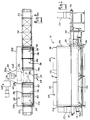
- Fig. 1 is a side elevational view of one embodiment of a convection type food cooking oven embodying the invention;
- Fig. 2 is top plan view of the oven as shown in Fig. 1;
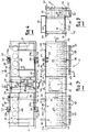
- Fig. 3 is an enlarged side elevational view of the hood assembly of the oven as shown in Fig. 1, and illustrating the position of the upper disposed duct fingers in the interior of the oven in relation to the fan means which circulates the heated gaseous cooking medium from the heater means to the duct fingers for impingement upon the food product, as well as the duct tubes enabling supply of the cooking medium to the base portion and lower disposed duct fingers;
- Fig. 4 is an enlarged top plan view of the hood portion as shown in Fig. 3 including the moisturizing means and the means by which the hood assembly may be selectively raised;
- Fig. 5 is an enlarged side elevational view of the hood portion as shown in Fig.3 showing more particularly the position of the upper disposed duct fingers and duct tubes associated with the hood portion;
- Fig. 6 is a partially broken, generally diagrammatic enlarged sectional view taken in general along the plane of line 6-6 of Fig. 3, and illustrating more particularly the construction of the hood portion including the flame tube associated with the heater means as well as a damping structure associated with the duct tubes therein;
- Fig. 7 is a partially broken, generally diagrammatic enlarged sectional view taken in general along the plane of line 7-7 of Fig.3, and illustrating more particularly the construction of the hood assembly including joints giving the hood portion flexibility for accommodating thermal expansion;
- Fig.8 is a partially broken, generally diagrammatic enlarged sectional view taken in general along the plane of line 8-8 of Fig. 4, and illustrating the unique support system for the hood assembly enabling thermal expansion and retaining sufficient strength therein;
- Fig. 9 is partially broken, generally diagrammatic enlarged sectional view taken in general along the plane of line 9-9 of Fig. 4, and illustrating more particularly the relative positions of the upper disposed duct fingers, the duct tubes as well as the flame tube and high pressure plenum in which the high pressure heated gaseous cooking medium is circulated;
- Fig. 10 is a partially, broken, generally diagrammatic enlarged sectional view taken in general along the plane of line 10-10 of Fig. 4, and illustrating the heater means including the flame tube in more detail;
- Fig. 11 is a partially broken, generally diagrammatic enlarged sectional view of a portion of the roof construction on the hood portion as shown in Fig. 3 showing in more detail the sectional structure of the hood portion allowing for thermal expansion;
- Fig. 12 is a partially broken, generally diagrammatic enlarged sectional view taken in general along the plane of line 12-12 of Fig. 11, and illustrating the outer skin configuration at the roof of the hood portion;
- Fig. 13 is an enlarged sectional view generally similar to Fig. 12 taken generally along the plane of line 13-13 of Fig. 11;
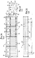
- Fig. 14 is a generally diagrammatic top plan view of the base portion of the oven as shown in Fig. 1 illustrating the lower disposed duct fingers and orifice plates which coact with the duct tubes forming a part of the hood portion of the oven;
- Fig. 15 is a generally diagrammatic enlarged side elevational view of the base portion as shown in Fig. 14;
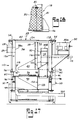
- Fig. 16 is a front elevational view of the base portion of the oven as shown in Fig. 14;
- Fig. 17 is a generally diagrammatic and enlarged side elevational view of the oven as shown in Fig. 1 showing more particularly the hood portion and base portions thereof in working relationship to one another so as to provide the cooking chamber of the oven;
- Fig. 18 is a partially broken, generally diagrammatic enlarged sectional view taken in general along the plane of
line 18 in Fig. 8, and illustrating the novel support structure for the hood portion of the oven allowing thermal expansion thereof; - Fig. 19 is an enlarged top plan view of a jet plate associated with the upper and lower duct fingers allowing for impingement of high velocity curtains of cooking medium onto a food product;
- Fig. 20 is an enlarged sectional view taken in general along the plane of line 20-20 of Fig. 19 showing the jet plate of the duct fingers;
- Fig. 21 is a partially broken bottom plan view of a lower disposed duct finger associated with the base portion of the oven;
- Fig. 22 is a side elevational view of the lower disposed duct finger as shown in Fig. 21;
- Fig. 23 is a front elevational view of the lower disposed duct finger as shown in Fig. 21;
- Fig. 24 is a sectional view taken in general along the plane of line 24-24 of Fig. 22 showing the relationship of the jet plate with the lower disposed duct finger;
- Fig. 25 is a side elevational view of an upper disposed duct finger associated with the hood portion of the oven;
- Fig. 26 is a partially broken top plan view of the upper disposed duct finger as shown in Fig. 25;
- Fig. 27 is a front plan view of the upper disposed duct finger as shown in Fig. 25;
- Fig. 28 is a sectional view taken in general along the plane of line 28-28 of Fig. 25 showing the upper disposed duct finger including jet plate associated therewith;
- Fig. 29 is a partially broken partial sectional view of a jack screw associated with the lift mechanism of the oven;
- Fig. 30 is a sectional view taken in general along the plane of 30-30 of Fig. 29; and
- Fig. 31 is a sectional view taken in general along the plane of 31-31 of Fig. 29.
- Referring now to the drawings, a preferred embodiment of the
oven 10 as shown in Fig. 1 comprises an enclosure assembly formed of anupper hood assembly 12 havingside walls top wall 12c andend walls upper hood portion 12 comprise an outer and inner skin to essentially form a double wall construction wherein an insulatingmaterial 16 will be disposed therebetween. Theend walls inlet opening 18 and outlet opening 20 respectively therein, through which food products are introduced into and removed from the oven. Theopenings outlet openings exhaust stack structures 22 of conventional known type along with anequilibration chamber 24 to help retain the heat within the oven and allow the cooked food products to adjust somewhat to atmospheric conditions upon removal from the oven. - The conveyor means 26 may be an endless pervious conveyor mechanism which extends through the oven from the
inlet 18 thereof and passes out theoutlet 20 in a continuous manner. Theconveyor 26 may be powered in a conventional manner by means of a motor (preferably a hydraulic motor) and allows food products to be transported through the oven at the desired speed to achieve the cooking characteristics desired by the food processor. Thehood portion 12 ofoven 10 acts in conjunction with alower base portion 14 of the oven enclosure to form the cooking chamber through which food product will pass during the cooking operation. - The
base portion 14 includesside walls 14a, 14b, bottom wall 14c, and endwalls upper hood portion 12 is selectively raisable from thelower base portion 14 for optimization of cooking of various food products within the oven as well as enabling access to the ovens interior for cleaning thereof. - A heating means 28 is mounted on a
side wall 12a of the upper hood portion, and may include a known combination of gas blower and burner unit for supplying a heated gaseous cooking medium into the oven enclosure. The heating means 28 may generate gaseous medium having a temperature of 1600°F (871 °C) or similar high temperatures. Theheater 28 may be supported at the location of theside wall 12a by means of a stand offplate 29. - It is understood that the heating means may alternatively be positioned on
side wall 12b of theupper hood portion 12 as is desired while still supplying the heated gaseous cooking medium for the oven. In this construction, a flame tube would extend across the high pressure plenum chamber so as to dispose the cooking medium into the cooking chamber. It is also noted that the positioning of theheater 28 on a side wall of the oven does not increase the height of the oven structure and will not impose any type of height limitations thereto. It is also noted that the heating means 28 directs the heated gaseous cooking medium to anoutlet port 28a which is in relatively close relationship to a means for incorporating moisture into the cooking medium such as a source ofmoisture 31 which may constitute steam spray outlets for supplying predetermined amounts of moisture to the gaseous medium being furnished by theheater 28. - At a central location of the
side wall portion 12b ofupper hood 12 is disposed a large suction fan means 30 which may be driven by means of anelectric motor 30a (as shown in Fig.2) which is operatively coupled to thelarge impeller fan 30b which acts to circulate the gaseous cooking medium through the oven at high pressure. Coupled to thefan 30b is ablower cone 32 which connects to thecooking chamber 36 of the oven through a gap in thehigh pressure plenum 34 in relatively close relationship to thedischarge duct port 28a of theheater 28. Theblower cone 32 is relatively deep and allows a large amount of cooking medium to be directed to the fan means 30 for distribution to the duct fingers at a high velocity. - As the
heater 28 generates and discharges the heated gaseous cooking medium at thedischarge duct port 28a, thefan 30 will suck the heated gaseous cooking medium as well as moisture generated at means 31 into theblower cone 32 at the upper portion of thecooking chamber 36. The heated gaseous cooking medium is discharged into the highpressure plenum chamber 34 in the oven which is separated from thecooking chamber 36 as will be fully described later. The highpressure plenum chamber 34 is adapted to transfer the heated and moisturized cooking medium to the duct fingers which are disposed above and below the food product traveling through the oven on the conveyor means 26. - The high
pressure plenum chamber 34 is separated from thecooking chamber 36 by means of a vertical dividing wall means 38 forming part of theupper hood assembly 12 as well as a similar divider in the base portion. Thevertical dividing wall 38 may also act as the support for the upperdisposed duct fingers 40 which are spaced relative to one another in the longitudinal direction of the oven as well as duct work for access to thehigh pressure plenum 34 comprising apertures in thewall 38. The upperdisposed duct fingers 40 may be anchored at their distal ends to thefront side wall 12a by means of finger supports 41 to ensure proper horizontal positioning thereof. Anexhaust stack 42 may be positioned on theside wall 12b in communication with the highpressure plenum chamber 34 for venting thechamber 34 if desired. Theexhaust stack 42 preferably embodies baffle means (not shown) for selectively restricting or preventing the ingress of gaseous medium to thestack 42 as is desired. The highpressure plenum chamber 34 may also be provided with baffle means to facilitate even distribution of the cooking medium. - There is also provided on
top wall 12c of theupper hood assembly 12explosion proof doors 44 andguards 46 which would allow the egress of the heated gaseous cooking medium from cookingchamber 36 upon the occurrence of an explosion or blowout within the oven. Theexplosion proof doors 44 are provided with a sealing means on their periphery so as to seal tightly against thetop wall 12c due to the weight of the doors themselves. Thedoors 44 will not interfere with the function of the oven except in the event of an explosion or the like. - Referring now to Figs. 3, 4 and 5, the
upper hood assembly 12 of the oven is shown in more detail. As mentioned previously, theupper hood assembly 12 may be selectively raised from thelower base portion 14 of the oven for optimization of the cooking process or for gaining access to the interior of the oven for cleaning or maintenance thereof. Theupper hood assembly 12 includes fan means 30 havingfan 30b andblower cone 32 mounted on theback side wall 12b of thehood 12. - As more distinctly seen in Fig. 3, the
upper hood assembly 12 also includes upperdisposed duct fingers 40 which are evenly spaced along the longitudinal direction of the oven which will be positioned directly above the conveyor means supported in the base portion of the oven as seen in Fig. 1. As mentioned previously, the upper hood assembly has a highpressure plenum chamber 34 and acooking chamber 36 which are separated in thehood 12 by a dividingwall 38 extending in the vertical direction. The upperdisposed duct fingers 40 are positioned in the cooking chamber and may be releasably supported on the dividingwall 38 in conjunction with apertures or duct work therein to properly position the fingers for cooking. - The
upper hood assembly 12 also comprisesduct tubes 48 which extend from the bottom edge of thehood assembly 12 to allow the heated gaseous cooking medium generated by heating means 28 to be directed to lower disposed duct fingers supported in thebase assembly 14 of the oven as will hereinafter be described. Theduct tubes 48 include guide rods orfingers 50 which extend therefrom in the downward direction and are curved or bent so as to facilitate coupling with thebase portion 14 of the oven as will be more fully described hereinafter. - The
duct tubes 48 also includeopenings 52 which are disposed in the highpressure plenum chamber 34 of theupper hood assembly 12. As seen in Fig. 5, theopenings 52 is an angled aperture which allows a maximum flow of heated gaseous cooking medium therethrough from the highpressure plenum chamber 34. The duct tubes are supported in position by means of a positioning detent 60 or by other suitable means so as to extend a predetermined distance below the bottom edge of the upper hood portion for engaging thebase assembly 14 as will be hereinafter described. - The
upper hood assembly 12 also includes support means 54 and 56 associated a the lift assembly means which allows the upper hood assembly to be selectively raised with respect to thebase portion 14 of the oven as previously described. As seen in Fig. 4, the upper support means 54 includes a drivensprocket 55 as well asidler sprockets 58 which are coupled by means ofdrive chain 59 to motor 57 positioned ontop wall 12c of the hood assembly. A second sub-loop ofdrive chain 59a couples one of thesprockets 58 with the drivensprockets 55 thereby separating the chain tension applied to each of thesprockets 55. Drivensprockets 55 of the upper support means 54 are positioned so as to lie in a horizontal plane such that upon activation of the motor 57, all of the drivensprockets 55 will be positively driven simultaneously without inducing extreme torques or other unwanted forces in the lift system or on the hood assembly. As will be described hereinafter, thedrive sprockets 55 are coupled to screw jacks for selectively raising thehood assembly 12 as is desired. Upon activation of the motor 57 a great amount of tension will be supplied to the drive chain, for example, upon the activation of the motor, there may be up to 200 lbs. of chain tension applied to supports 54. It therefore may be desirable to provide further support such ascompression members 61 formed into an H-shaped frame to oppose chain tension which are coupled to the upper support means 54. Thecompression member 61 may be formed as shallow channels which will help to oppose this chain tension and the lift assembly of the invention will enable thermal expansion of the upper hood assembly to occur. In this regard, the H-shaped frame includingcompression members 61 is not attached to thehood assembly 12 except at a central portion of the oven near motor 57. - Although the support means 54 are coupled to the screw jacks forming part of the lift assembly, the weight of the
hood assembly 12 is essentially carried by the lower support means 56 which are mounted at spaced positions at the lower edges of thehood assembly 12. The lower support means 56 forming part of the lift assembly for thehood assembly 12 are constructed as support shoes which extend under the edges of the hood assembly as seen in Fig. 5. - As will be more fully described hereinafter, the
lower support shoes 56 act in conjunction with support beams running the length of theupper hood assembly 12 so as to maximize the strength of the hood assembly while enabling thermal expansion thereof. The support shoes 56 include pivoting or rolling means to allow the hood assembly to slide thereon while fully supporting the weight thereof. It should be recognized that upon activation of the motor 57, the drivensprockets 55 onupper supports 54 will rotate simultaneously to enable simultaneous operation of the screw jacks to which the driven sprockets are attached for lifting of theupper hood assembly 12. It is a novel aspect of the invention that theupper hood assembly 12 may be lifted a predetermined amount while remaining in coupling relationship with the lower base portion of the oven. In this way, the upperdisposed duct fingers 40 may be selectively positioned at varying heights above theconveyor system 26 on which food products are disposed. Therefore, theupper duct fingers 40 may be positioned so as to optimize the cooking of any particular food product which is being cooked. - In the type of oven which utilizes impingement of a heated gaseous cooking medium onto the surfaces of the food product passing through the oven on a conveyor system, it is recognized that the heat transfer characteristics of the gaseous medium change according to the distance of the duct fingers, which supply the impinging cooking medium, from the food product itself. Thus, the upper
disposed duct fingers 40 may be selectively positioned at the optimum height for any particular food product which is to be cooked by raising or lowering the hood to this desired position. By extending theduct tubes 50 substantially below the lower edge of thehood assembly 12, distribution of the heated gaseous cooking medium to the lower disposed duct fingers in the base portion of the oven may be provided at varying heights of thehood assembly 12. - As will be seen more clearly in subsequent figures, the
hood assembly 12 also includesblades 62 extending from the lower edge of the hood assembly which coact with water troughs formed on the base portion so as to form a deep water seal allowing the selective height adjustment of thehood assembly 12 while the oven is operational. It is also noted that the moisturizing means 31 may be positioned at various locations within thecooking chamber 36 so as to provide for the incorporation of the desired amount of moisture into the heated gaseous cooking medium. - Turning now to Figs. 6-13, there are shown more detailed views of the hood assembly construction. In Fig. 6, there is shown a cross-sectional view through the
upper hood assembly 12 showing more distinctly theduct tube 48 associated therewith. A dividingwall 38 separates the highpressure plenum chamber 34 from thecooking chamber 36 and includes an apertures for access to thechamber 34 at the location of theduct fingers 40. It is also noted that theside walls inner skins - The
duct tubes 48 disposed within the highpressure plenum chamber 34 for supplying a heated gaseous cooking medium to the lower disposed duct fingers within the base portion of the oven may include a damping means 70, positioned over theupper opening 52 to force the high pressure cooking medium into a desired distribution for impingement on the food products being cooked. The damping means 70 also allows adjustment of the quantity of heated gaseous cooking medium being directed to either the upper or lower duct fingers respectively. The damping means 70 is adjustable within opening 52 in a range which may extend between 45 degrees and 90 degrees to control the amount of cooking medium entering theduct tubes 48 and its velocity. There may be provided a manual lever 60, as seen in Fig. 5 having a string of holes and a detent coacting with a spring loaded ball bearing to allow manual positioning of damping means 70 over theupper openings 52 in theduct tubes 48. - Alternatively, the adjustment of damping
means 70 may be achieved automatically by means of a lever extending to support the damping means 70 which may be driven by a screw jack coupled to a stepper motor for selectively positioning the damping means by electronic control. Depending on the particular food product which is being cooked, a damping means 70 may be positioned for best cooking of that product before or during operation of the oven. - In Fig. 7 there is shown a lengthwise sectional view of the
upper hood assembly 12 which more clearly shows the sectional nature of its construction. As is seen in Fig. 7, the upper hood assembly is constructed of a plurality of sections, wherein thermal expansion of the hood assembly will be accommodated by movement of the individual sections while maintaining the strength of the hood assembly as is desired. For example,side wall 12a of the hood assembly may comprisesections weld joints - For example, during operation of the oven, there may be up to 1/2 inch (12,7 mm) of thermal expansion axially along the length of the oven which would necessarily put a great amount of strain on the hood assembly. Separating the hood assembly into a plurality of sections introduces enough flexibility to compensate for this thermal expansion. A novel support structure for the hood assembly to be described later retains sufficient strength to prevent the hood assembly from collapsing.
- Also seen in Fig. 7, the
duct fingers 40 having slottedapertures 132 therein to provide a sheet of impinging cooking medium to the food products are shown. In some instances, an even distribution of cooking medium through the duct fingers is not achieved for one reason or another. It is desirable to equalize cooking characteristics over the extent of the conveyor belt which may be achieved by varying the geometry of theslots 132 in individual fingers across the belt. The geometry may be varied by changing the width ofslots 132 across the belt to achieve even cooking characteristics. For example, if less cooking is achieved near the ends of the oven, theslots 132 may be widened to increase the flow of cooking medium therethrough and increase cooking in the area. In this way, any local variations in cooking within the oven may be compensated for. In Fig. 7, theslots 132 at the end of the oven may be wider than the slots in theduct fingers 40 near the central part of the oven. - As seen more distinctly in Fig. 8, the high
pressure plenum chamber 34 having theduct tube 48 disposed therein withupper aperture 52 receiving high pressure cooking medium for distribution to the lower disposed duct fingers is shown. Theduct tube 48 includes guide rods orfingers 50 having a substantial length which facilitate proper positioning thereof within the orifice plate of the base portion of the oven as will hereinafter be described. - The
guide rods 50 have a substantial length so as to create gaps between theduct tube 48 and orifice plate of the base portion so as to reduce the surface area ofduct tube 48 which may tend to attract cooking residue during the cooking process. In order for theduct tubes 48 to freely move in the vertical direction into and out of its operational position with the base portion, it is necessary to prevent the congealing and caking of cooking residue on theduct tubes 48 which could possibly weld the duct tubes to the base portion of the oven. The telescoping function of the duct tube with respect to the base portion of the oven is important for adjustability of the upper disposed duct fingers and optimization of the cooking process. - Also seen in Fig. 8 is the support construction of the walls of the upper hood assembly as shown at 78 and 79. As mentioned previously, it is desirable to allow the upper hood portion a degree of flexibility to accommodate thermal expansion during operation of the oven while retaining sufficient strength to prevent collapse of the hood assembly or other associated problems. The plurality of sections and joints described with relation to Fig. 7 allow sufficient flexibility for thermal expansion but detract from the strength of the overall hood construction.
- To reinforce the strength of the upper hood assembly there may be provided support means 78 and 79 which comprise two rectangular beams which run the length of the hood assembly and may be welded at a mid-portion of the oven. The rectangular beams add sufficient reinforcing strength to the hood assembly for long use and durability of the oven. As will be seen with reference to Fig. 18, the
lower beam structure 78 acts in conjunction with the lifting means associated with the hood assembly as previously described to maintain the flexibility of the hood assembly for thermal expansion. - The
support assembly 78 includesbeams side walls channels 82 welded thereto so as to distribute stress over an expansive area of the sheet metal skin of the hood assembly. For example, at every joint in the sheet metal which allows flexibility but also forms an area of weakness in the hood, there may be provided a supportingchannel 82 coacting with the beam supports 78 to allow the weight of the hood to be supported by the support beams while enabling axial movement of the hood sections by means ofchannels 82 which are free to move in the axial direction. As also seen in Fig. 18, thelower shoe support 56 associated with the lifting means of the invention may include a pivot orroller 83 to allow axial movement of thehead assembly 12. theshoes 56 will act to hold thesupport beam structure 78 without inducing undue stress on the hood assembly during the lifting or expansion thereof. - Turning to Figs. 9 and 10, the enlarged sectional views of the upper hood assembly show more distinctly the position of the upper duct disposed duct fingers, duct tubes as well as the area of the fan means for circulating the heated gaseous cooking medium through the oven. It is noted that these figures also show the central portion of the oven which separates upper disposed duct fingers and duct tubes on either side thereof and houses the fan means 30.
- This middle section houses the fan means and blower on the
rearward side wall 12b of the hood assembly at a central location thereof. As seen in Fig. 9, theblower cone 32 mounted in this central location is in close proximity to the source of heated gaseous cooking medium generated atheater 28. As mentioned previously, the heated cooking medium is drawn intoblower cone 32 by means of the blower orfan 30b as seen in Fig. 2. The heated gaseous cooking medium will then be distributed to the upper and lower disposed duct fingers through highpressure plenum chamber 34 separated from the cooking chamber by dividingwall 38 and dividingwall 123 in the hood and base portions respectively. - In Fig. 10 there is shown more distinctly the positioning of the fan means which is centrally located and supported on the
back side wall 12b of the hood assembly at a centrally located aperture in the highpressure plenum chamber 34. A fan means 30b is rotated at a high rate by themotor 30a as shown in Fig. 2 which may, for example, be a 60 Hz. motor to generate very high velocity circulation of the heated gaseous cooking medium within the highpressure plenum chamber 34 for distribution to the upper and lower disposed duct fingers. - The high
pressure plenum chamber 34 comprises relatively restrictive air passages for distribution of the high velocity cooking medium to the duct fingers to generate impingement velocities of the cooking medium in a range between 4,500 and 5,500 feet per minute. With velocities of the impinging cooking medium in this range, it has been found with the oven configuration of the invention that cooking times may be reduced by up to 20-30% based upon cooking test data of various food products. For example, in prior art ovens utilizing impingement of a heated gaseous cooking medium, velocities in the range of 4,300 feet per minute have been generated for the expedient cooking of food product. The impingement of the heated gaseous cooking medium allows surface characteristics such as browning, searing and the like to be achieved while cooking food products, but it is always desirable to reduce the dwell time of the food products in the oven when being cooked. A decrease of 20-30% in the dwell time necessary for cooking of various products greatly enhances the capabilities of the food processor and allows more efficient and effective cooking procedures. In the highpressure plenum chamber 34, it may also be desirable to include baffle means for distributing the cooking medium evenly to the upper and lower duct fingers. - Similarly to the side walls of the oven enclosure, the
top wall 12c as shown in Figs. 11-13 is formed in sections which allow thermal expansion thereof when the oven is operational. As seen in Fig. 11, thetop wall 12c of the oven enclosure includesvarious sections - Additionally the top wall portion includes explosion
proof doors 44 for allowing the egress of the cooking medium from the interior of the oven in the event of an explosion or the like, as seen in Figs. 12 and 13. The top wall construction includes inner and outer skins where insulation may be provided therebetween as previously described. The explosionproof door 44 is sealed onto thetop wall portion 12c such as by a rubber gasket type seal or the like. Due to manufacturing tolerances in the weight of the door, it has been found that the double-skin construction may make theexplosion proof doors 44 too heavy necessitating eliminating one of the skins as shown in Figure 12. It is of course recognized that other constructions are possible for the explosion proof door construction to meet the weight limitations while insuring proper insulating characteristics and sealing thereof. - Turning now to Figures 14, 15 and 16, the base portion on 14 of the enclosure is shown in more detail. The
base portion 14 as seen in Figure 14 includes lower disposed duct fingers which are spaced in the lengthwise direction underneath the conveyor means 26 upon which food products to be cooked are disposed. Thelower base portion 14 is similarly separated into separate chambers by dividingwall 123 which in conjunction with the hood assembly define thecooking chamber 36 and the highpressure plenum chamber 34. It is noted that the high pressure cooking medium from the highpressure plenum chamber 34 of the upper hood assembly may be distributed to the lower duct disposedduct fingers 90 by means of anorifice plate 91 havingapertures 92 therein which coact with theduct tubes 48 of theupper hood assembly 12. It is noted thatduct fingers 90 may extend through the central portion of the oven to provide cooking across the entire belt. - It is a special feature of the invention that the
orifice plates 91 are free to float in a horizontal plane so as to allow self-adjustment thereof with theduct tubes 48 which may be moved in the axial direction of the oven by thermal expansion. It is recognized that thebase assembly 14 may be supported on aframe structure 94 as seen in Figure 16 which is relatively cool as compared to the oven enclosure. Thehood assembly 12 is subjected to thermal expansion in the axial direction when the oven is operational requiring self-adjustment of the orifice plates so as not to induce unwanted stress on the hood assemble orduct tubes 48 thereof. Similarly, if thehood assembly 12 is raised from thebase assembly 14 when the oven is hot, there may be presented a problem in that some portions of the oven enclosure may cool significantly faster than other portions causing contraction thereof and subsequently misalignment of theduct tubes 48 with theapertures 92 inorifice plates 91. For this reason, floating in the horizontal plane of theorifice plate 91 allows theguide members 50 of theduct tubes 48 to reposition theapertures 92 inorifice plate 91 upon subsequent repositioning of thehood assembly 12 on thebase assembly 14. - As mentioned previously, the guide means 50 on the
duct tubes 48 are constructed so as to allow the surface area of the tubes in relation to theorifice plate 91 to be reduced. This may also be accomplished by providingnotches 94 in theapertures 92 oforifice plate 91 enabling reduction of the guide rod length. - In another aspect of the invention the
orifice plate 91 may act as a mechanical fuse wherein, in the event that cooking residue from the food products happens to weld theduct tubes 48 andorifice plates 91 together, theorifice plates 91 are designed to shear upon the application of an amount of force allowing separation of thehood assembly 12 from thebase assembly 14 without damaging other components of the oven. For example, cooking residue may congeal around theduct tubes 48 and onto theorifice plate 91 creating 200-300 psi sheer forces which weld thehood assembly 12 to thebase assembly 14. If thehood assembly 12 was to be raised with theduct tubes 48 welded to theorifice plates 91 in this manner, it is possible that theentire base assembly 14 of the oven would also be raised in conjunction with thehood assembly 12. Without the mechanical fuse construction of theorifice plate 91, the separation of thehood assembly 12 from thebase assembly 14 would necessitate the use of complicated measures as well as time and cost to separate the assemblies and possibly incurring extensive damage to the oven. - The
base assembly 14 also includes adeep water trough 96 which acts in conjunction withblades 62 formed on theupper hood assembly 12 to form a water seal around the periphery of the oven except in the area ofinput 18 andoutput 20 of the oven. Thewater trough 96 is necessarily deep to insure continuous sealing during vertical adjustment of thehood assembly 12 from thebase assembly 14 by the lifting means associated with the hood. In this way, the operation of the oven is maintained while adjustment of thehood assembly 12 and therefore the upperdisposed duct fingers 40 is performed to enable positioning of the upperdisposed duct fingers 40 at the location where cooking of any particular food product is optimized. - The
base assembly 14 also includes the conveyor means 26 which is an endless pervious conveyor mechanism as shown in Figure 1. Theconveyor system 26 may be supported on one side thereof by support means 97 which extend from the conveyor belt support to a sidewall of thebase assembly 14. On the other side of the conveyor belt support, as shown at 98, there may be provided hinges for allowing pivoting of the conveyor belt support for access to the lowerdisposed duct fingers 90 within thebase assembly 14. The pervious conveyor belt of the conveyor system has enough flexibility to allow pivoting of the conveyor support upwardly to a sufficient extent to allow removal of the lowerdisposed duct fingers 90 for cleaning or maintenance thereof. Similarly, the lowerdisposed duct fingers 90 may include finger support means 93 which extend from the distil ends offingers 90 to the upper ledge of front side wall 14a to properly position theduct fingers 90. - As seen in Figure 15, the
base assembly 14 also comprises a water cooledplate 99 which is positioned at an angle in the bottom of thebase assembly 14 so as to catch and direct cooking residue or the like continuously to anoutlet drain aperture 100 formed in the bottom wall of thebase assembly 14. Adisposal pipe 102 may be connected to theaperture 100 directing the cooking residue and the like out of the oven and to a catch box 104 as shown in Figure 1 of a conventional type, adapted to receive the cooking residue and drippings from the food products during the cooking process. The slopingbottom wall surface 99 is seen more distinctly in Figure 16 for directing such waste to theopening 100 in the bottom wall of thebase assembly 14. - Turning now to Figure 17, the
hood assembly 12 andbase assembly 14 are shown in their operational position whereby the operation of the oven can be seen more distinctly. As it is shown in Figure 17, theupper hood assembly 12 includes downwardly extendingblades 62 which coact with thewater troughs 96 formed in thebase assembly 14 to allow a water seal to be formed around essentially the entire periphery of the oven enclosure at the junction of thehood assembly 12 with thebase assembly 14. In operation, the upperdisposed duct fingers 40 are positioned directly above the conveyor means 26 on which food products to be cooked are to be placed. Similarly, the lowerdisposed duct fingers 90 are disposed directly underneath the conveyor means 26 for impingement of a heated gaseous cooking medium to both upper and lower surfaces of the food products passing through the oven on the conveyor means 26. - As described previously, the
hood assembly 12 includes fan means 30 having amotor 30a drivingly coupled todriveshaft 112, operatively connected to thefan 30b for rotation thereof. Theblower cone 32 extends through the dividingwall 38 which separates the highpressure plenum chamber 34 from thecooking chamber 36 so as to define and separate the high pressure side of thefan 114 disposed withinplenum chamber 34 and the relatively low pressure or recirculation end of the fan as shown at 116. In operation, the heated gaseous cooking medium generated by the heating means 28 as seen in Figure 2, disposes the heated cooking medium into the cooking chamber in the vicinity of theblower cone 32. Thefan 30b will suck in the heated cooking medium at 116 for subsequent high pressure circulation at thehigh pressure side 114 of the fan in highpressure plenum chamber 34. Similarly, cooking medium which has already been applied to the food product between the upper and lowerdisposed duct fingers arrow 118. The high velocity heated cooking medium generated athigh pressure side 114 of the fan means is directed into the upperdisposed duct fingers 40 atposition 120 for impingement to the food products thereto. Similarly, the high velocity cooking medium is directed intoduct tube 48 which coacts withorifice plate 91 forming part of thebase assembly 14. The high velocity cooking medium is thus directed to the lowerdisposed duct fingers 90 atposition 122 by means ofduct tube 48 andorifice plate 91 for impingement of the cooking medium to the underside of the conveyor means 26. - As seen in Figure 17, as long as the
blades 62 are disposed inwater trough 96 to form the water seal around the periphery of the oven enclosure, the oven can remain operational to provide impingement of the heated gaseous cooking medium onto food products passing through the oven on the conveyor means 26. Thus, the position of the upperdisposed duct fingers 40 can be varied in the vertical direction the length of theblades 62 to provide proper placement of theduct fingers 40 for optimum cooking of the particular food product. - In order to accomplish raising of the
upper hood assembly 12 there are provided lift assembly means which may comprisescrew jacks 110 havingsupport shoes 56 mounted under and supporting theside walls hood assembly 12. The support shoes 56 are secured to thescrew jacks 110 such that upon operation of the screw jacks the shoes will be lifted and will correspondingly lift thehood assembly 12 to its desired position. The lift means 110 may be operated automatically such as by a micro-adjust controlling means to position the upperdisposed duct fingers 40 in the optimum cooking position for a particular food product being passed through the oven, and may be adjusted during a cooking cycle for various food products while the oven is operational. Similarly, the lift means 110 may completely disengage theupper hood assembly 12 from thelower base assembly 14 for access to the interior surfaces of the oven for cleaning and maintenance thereof. The lift means 110, as will be more fully described in reference to Figures 29-31, allows theupper hood assembly 12 to be raised a significant distance up to 3 feet from thebase assembly 14 for access to the oven's interior for easy cleaning, as well as removal of the duct fingers for cleaning thereof, or other maintenance operations. - With the oven construction as shown in Figure 17, it has been found that extremely high velocities of the heated gaseous cooking medium may be obtained for impingement onto the food products by means of upper and lower
disposed duct fingers disposed duct fingers 40 allows for optimization of the cooking process during a cooking cycle for various food products, as well as enabling easy and effective cleaning of the interior surfaces of the oven in an efficient manner. - Turning now to Figures 19-28, the upper and lower
disposed duct fingers disposed duct fingers jet plate 130 facilitating impingement of the heated gaseous cooking medium onto a food product. Thejet plate 130 consists of an apertured plate member withapertures 132 comprising slots disposed along the lengthwise edges thereof. Due to manufacturing tolerances, it may be necessary to includeunbroken sections 133 in theslots 132 although optimally it would be desired to exclude these. Each of theapertures 132 in thejet plate 130 is formed as a L-shaped slot formed on the lower edges of thejet plate 130. As seen in Figure 24, a portion of theslots 132 extends along the bottom ofjet plate 130, as well as extending along thelongitudinal side walls 134 of thejet plate 130 as seen in Figure 20. In this way, theside walls 134 in conjunction with the side walls of the duct fingers act to direct the high velocity cooking medium out of theslots 132 and in an essentially vertical sheet or curtain of the cooking medium for impingement on the food product. The width of the slot through which cooking medium will pass is found to be optimum at about 1/8 inch (3.2 mm) but goods results are achieved with slots up to 1/4 inch (6.35 mm) in width. As mentioned previously, theslots 132 may also be constructed to be wider to let a greater flow of cooking medium therethrough for even cooking. It is also noted that thejet plates 130 may accommodate a collimating plate (not shown) which may comprise a plate have circular apertures therein for directing the flow of cooking medium in a perpendicular direction to the collimating plate. The use of a collimating plate would induce a pressure drop thereby reducing the velocity of the impinging cooking medium, and it may be preferable to exclude the collimating plate to achieve the maximum velocity of the impinging medium. It is also recognized that other aperture geometries may be utilized with the duct fingers to provide impingement of cooking medium to the food product. - As seen in Figures 21 to 24, the lower
disposed duct finger 90 comprises generally a fabricated sheet metal member having generally triangular shapedside walls 136, a generally slopingbottom wall 140, and a generallyvertical end wall 142 with the top of the duct finger being open as at 144 and also being open at theright hand end 146 thereof. - The sloping
bottom wall 140 preferably has opening 148 (Figure 22) formed therein for permitting drippings falling down from the conveyor means 26 into the chamber defined by theduct finger 90, to flow out of the duct finger onto the slopingbottom wall surface 99 as shown in Figure 17, for example. - The
side walls 136 of the lowerdisposed duct fingers 90 preferably has headedpins 150 projecting outwardly therefrom which are adapted for receiving thejet plate 130 and securing it in thelower end 144 thereof. The top of the rearward end portion of eachduct finger 90 is preferably provided with a hook shapedmember 152 adapted for coacting and retaining ajet plate 130 therein. Theduct finger 90 is adapted to be removably mounted on a supporting vertical wall such as dividingwall 123 by means ofhook members 154 so as to hang theduct finger 90 in the desired position below the conveyor means 26. Theduct finger 90 is positioned on the dividingwall 123 in coacting relationship with apertures or duct work formed in the dividingwall 123 for furnishing the heated cooking medium from theduct tube 48 into theduct finger 90 and upwardly through the associatedjet plate 130 to impinge upon the under side of the conveyor means 26 for cooking food products thereon. - Referring now to Figs. 25-28, the upper
disposed duct finger 40 shown in more detail and is of a similar construction to that of the lowerdisposed duct finger 90. Theduct finger 40 comprises a fabricated sheet metal member preferably made by stainless steel and having generally triangular shapedside walls 160, a slopingtop wall 162, and generally verticalouter end wall 164 as well as open bottom andback walls jet plate 130 is adapted to be received in the bottomopen end 166 ofduct finger 40 and is retained therein by a key lock mechanism similar to that of the lowerdisposed duct finger 90. Theduct finger 40 includes hook shapedmembers 170 adapted to releasably secure theduct finger 40 onto the dividingwall 38 over duct work in the dividing wall such that the upperdisposed duct finger 40 will receive heated air from thepressure side 114 of thefan 30b and highpressure plenum chamber 34 as shown in Fig. 17. - It is noted that both the upper and lower
disposed duct fingers disposed duct fingers 90 so that they may be positioned at varying heights away from conveyor means 26 for optimum cooking of particular food products. Although thelower duct fingers 90 are not able to be repositioned during a cooking cycle, and repositioning thereof is somewhat inconvenient, desired positions for certain food products are still able to be provided for optimum cooking in conjunction with the selectively adjustable upperdisposed duct fingers 40 movable with thehood assembly 12. - Turning now to Figs. 29-31, the lifting means 110 of the invention comprising a screw jack associated with the
hood assembly 12 of the oven is shown in more detail. Thelift assembly 110 includes upper andlower support shoes support shoe 56 coacts with support means running the length of thehood member 12 and essentially supports the weight of the hood thereon. Thelift assembly 110 further includes a power screw means 180 which extends in the vertical direction fromlift assembly 110 and may be provided with a driven sprocket 55 (shown in Figs. 4 and 5) thereon for coupling to a positive timing driving system. - The
lift assembly 110 further comprises outer andinner tubes power screw 180. Aflange member 186 coacts with thepower screw 180 as well asbumper tube 188 and aguide tube 189 so as to selectively moveouter tube 182 relative toinner tube 184 upon activation of a drive means. Thepower screw 180 is supported for rotational movement within abearing sleeve 181 and bearingplate 182 supported atupper support 54 oflift assembly 110. There may also be provided a lower disposed support shoe 190 for supporting thebase assembly 14 of the oven enclosure. - It should be recognized that the
screw jacks 110 and driving means as described with reference to Fig. 4 provides a supporting exoskeleton type of arrangement which enables proper support and lifting capabilities while allowing thermal expansion of the oven to occur. Upon activation of the drive motor 57, adrive chain 59 acting on drive sprockets associated withpower screw 180 will act to simultaneously rotate thescrew jacks 110 for vertical movement of thehood 12. The drive sprockets 55 associated with thepower screw 180 are positioned in a coplanar manner such that upon activation of the motor 57 a positive timing relationship simultaneously rotate each of thedrive sprockets 55 on the respective power jacks of thelift assembly 110. Thus, at the location of each screw jack of the lift assembly, thehood assembly 12 will be selectively raised or lowered simultaneously to the desired height for operation or cleaning of the oven. - In the embodiment of the oven as disclosed herein, it is found that extremely high velocity of the impinging cooking medium can be obtained within the range of 4500 to 5500 feet per minute (22,9 to 27,9 m/s). In the preferred embodiment, the temperature of the heated medium may fall within the range of 200°F (93°C) to 700°F (371°C) and usually operation of the oven occurs within the range of 450°F to 500°F (232 to 260 °C). By the increase of velocity of the impinging cooking medium, the dwell time necessary to provide the proper cooking characteristics to any particular food product may be reduced by up to 20 to 30% over prior art ovens. Typical cooking times may vary from nominal cooking times to 20 to 30 minutes depending upon the particular food product. The linear velocity of the conveyor means 26 disposed between the upper and lower disposed duct fingers in the oven construction is thus selected for the desired dwell time of the particular food product to provide the desired cooking characteristics thereof. Similarly, the temperature and incorporation of moisture into the heated cooking medium is selected to provide the desired characteristics to the cooked food product.
- It should be recognized that the construction of the oven as disclosed herein expands the abilities of the food processor to cook mass quantities of food products in an extremely efficient and effective manner. By allowing the duct fingers to be selectively positioned for optimum cooking of any particular food product, the food processor may cook various food products within the same cooking cycle while optimizing the cooking process. Similarly, the impingement of the heated cooking medium allows for various surface characteristics such as browning and the like to be achieved while optimizing the full or partial cooking of a food product within the oven. The oven construction also allows easy and effective cleaning of the interior surfaces thereof without being extremely time consuming or inconvenient.
- The adjustable cooking oven of the invention allows a great amount of flexibility to the food processor to enable mass quantities of food products to be quickly and efficiently cooked with the desired characteristics.
Claims (27)
- A food cooking oven comprising an upper hood means (12) and base means (14) which are separable from one another and define a substantially closed enclosure except for an inlet (18) and outlet (20) in said enclosure, wherein said hood comprises side walls (12a), end walls (12d, 12e), and a top wall (12c), and said base means (14) comprises side walls, end walls and a bottom wall, said enclosure defining a cooking chamber (36) for receiving food product therein, means (26) for conveying food product through said chamber from said inlet (18) and exiting through said outlet (20), heater means (28) extending through a side wall of said cooking chamber (36) for heating a gaseous medium, suction fan means (30) on a side wall of said cooking chamber (36) in relatively closely spaced relation from an outlet of said heater means, a source of moisture (31) disposed in relatively closely spaced relation to said outlet (20) of said heater means (28) for mixing moisture with said gaseous medium from said heater means, means disposed above and below said conveying means (26) for directing said gaseous medium to opposite sides of said conveying means for impingement onto and cooking of food products thereon, a second chamber (34) separate from said cooking chamber (36) and in communication with the pressure side of said fan means (30) for directing the mixture of said gaseous medium and moisture to said means disposed above and below said conveying means for impingement of said gaseous medium onto said food products, wherein at least certain ones of said means disposed above and below said conveying means are adapted to be selectively movable in a vertical direction relative to said conveying means while said oven is being operated to allow the cooking characteristics of the oven to be varied during operation of the oven.
- An oven in accordance with claim 1, wherein said means disposed above and below said conveying means (26) for directing said gaseous medium to opposite sides of said conveying means comprises a plurality of generally horizontally spaced duct fingers (40) disposed in said cooking chamber (36) and communicating with said second chamber (34) by duct means.
- An oven in accordance with claim 2, wherein said duct fingers are located on a vertical dividing wall means which acts to separate said cooking chamber (36) from said second chamber.
- An oven in accordance with claim or 3, wherein said duct fingers include a chamber having at one side thereof a jet plate (130) comprising slots (132) formed therein for directing said gaseous medium out of said chamber as a sheet of gaseous medium which will impinge upon said food products for cooking thereof.
- An oven in accordance with claim 4, wherein said slots in said jet plate have a width within the range between 1/8 inch and ¼ inch (3,17 and 6,35 mm).
- An oven in accordance with claim 4 or 5, wherein said slots (132) in said jet plate (130) have a width which may be varied along the length of said oven in individual ones of said duct fingers so as to equalize cooking of said food products throughout the extent of said oven.
- An oven in accordance with any one of the preceding claims, wherein said hood means (12) includes a lifting means (110) adapted to support said hood means and to selectively raise or lower said hood means (12) in relation to said base means (14).
- An oven in accordance with claim 7, wherein said lifting means (110) allows selective raising or lowering of said hood means (12) and said means disposed above said conveying means for directing said gaseous medium onto said conveying means for impingement onto and cooking of food products thereon to be adjusted in essentially the vertical direction for optimization of the cooking process during operation of said oven.
- An oven in accordance with claim 7 or 8, wherein said lifting means (110) allows said hood means (12) to be fully disengaged from said base means (14) for access to the interior surfaces of said oven to facilitate cleaning and maintenance operations.
- An oven in accordance with claim 7, 8 or 9, wherein said lifting means (110) includes a plurality of screw jacks positioned around the periphery of said hood means (12), each having a driven sprocket associated therewith which is operatively coupled to a driving means for simultaneous rotation of each of said driven sprockets for operation of said screw jacks.
- An oven in accordance with claim 10, wherein each of said driven sprockets on said screw jacks is coupled to said driving means by drive chain means, and support means are provided between said driving means and said driven sprockets so as to oppose drive chain tension during operation of said drive means.
- An oven in accordance with claim 11, wherein said driven sprockets are coupled to said drive means by means of a sub-loop of drive chain so as to separate drive chain tension to each of the drive sprockets, wherein said sub-loop of drive chain is coupled to a drive idler sprocket which itself is driven by said drive means.
- An oven in accordance with any one of the preceding claims, wherein said hood means (12) includes blade means extending below the bottom edge of said hood means for operationally connecting to said base means to provide said substantially closed vapor leak proof enclosure at various elevations of said hood means.
- An oven in accordance with claim 13, wherein said blade means coacts with a deep water trough formed on said base means so as to provide a water seal around the periphery of said enclosure to allow vertical displacement of said hood means while maintaining said water seal.
- An oven in accordance with any one of the preceding claims, wherein said hood means (12) includes duct tube means extending below the bottom edge of said hood means to act in conjunction with orifice means in said base means to direct said gaseous medium from said second chamber to said means disposed below said conveying means for directing said gaseous medium onto the bottom side of said conveying means for impingement onto and cooking of food products thereon.
- An oven in accordance with claim 15, wherein said duct tube means is telescopically coupled to said orifice means in said base means so as to direct said gaseous medium to said means disposed below said conveying means at various elevations of said hood means.
- An oven in accordance with claim 15 or 16, wherein said orifice means comprises a plate which is movable in a horizontal plane to provide self-adjusting of the position of said plate in conjunction with the position of said duct tube means in said hood means.
- An oven in accordance with claim 15, 16 or 17, wherein said duct tube means includes damping means in coacting relationship with said second chamber for selectively adjusting the amount of flow of cooking medium from said second chamber to said means disposed below said conveying means for directing said gaseous medium onto siad conveying means.
- An oven in accordance with any one of claims 15 to 18, wherein said duct tube means include guide means to act on said orifice means of said base means to facilitate the self-adjustment of said orifice means to coact with said duct tube means.
- An oven in accordance with claim 19, wherein said guide means comprises rods having the substantial length so as to reduce the surface area contacting said orifice plate means to prevent congealing of cooking residue at the junction of said duct tube means and said orifice means.
- An oven in accordance with any one of claims 15 to 20, wherein said orifice means includes apertures being of generally circular shape and having notches formed at discrete intervals therearound so as to reduce the surface area of said orifice plate means which contacts said duct tube means so as to prevent congealing of a cooking residue at the junction of said orifice means and said duct tube means.
- An oven in accordance with any one of the preceding claims, wherein said hood means includes a plurality of support beams positioned at a lower edge of said side walls of said hood means which are movably coupled to channel means secured on said side walls to provide support for said hood means while allowing axial movement thereof.
- An oven in accordance with claim 22, wherein said hood means includes a lifting means for displacing said hood means in a vertical direction, wherein said lifting means is movably coupled to said support beams to thereby support said hood means and enable vertical and axial movement thereof.
- An oven in accordance with any one of the preceding claims, wherein the interior of said oven is comprised of stainless steel.
- A method of cooking food products in an oven including a substantially closed vapor leak proof elongated enclosure having an inlet (18) and outlet (20) in opposite end walls of the enclosure, and including conveyor means (26) for conveying food product through the cooking chamber (36) in said enclosure from said inlet (18) and exiting through said outlet (20), wherein said enclosure is formed from selectively separable hood means (12) and base means (14), comprising providing a source of gaseous cooking medium and directing it into said cooking chamber (36), applying moisture to said cooking medium closely adjacent to said source of gaseous cooking medium and then sucking by fan means (30) the moisturized cooking medium from said cooking chamber into another chamber separate from but adjacent to said cooking chamber, then forcing the moisturized cooking medium via said other chamber to means disposed above and below said conveying means for directing said gaseous medium toward the respective confronting surfaces of said conveyor means to cause impingement of said gaseous cooking medium on the food products, and then recirculating said cooking medium from said cooking chamber (36) back into said other chamber via said fan means (30), and providing for adjustment of the elevation of at least certain of said means disposed above and below said conveying means while said oven is operated whereby the cooking characteristics of the oven may be varied and the cooking operation may be optimized during operation of said oven.
- A method in accordance with claim 25, including adjusting the elevation of said hood means (12) in relation to said base means to provide for said adjustment of the elevation of said means disposed above said conveying means for directing said gaseous medium toward the upper confronting surface of said conveyor means.
- A method in accordance with claim 25 or 26, wherein said forcing of said moisturized cooking medium is provided to duct finger members disposed above and below said conveyor means for producing a high velocity sheet of cooking medium impinging upon said food product adapted to be moved through said oven on said conveyor means.
Applications Claiming Priority (3)
| Application Number | Priority Date | Filing Date | Title |
|---|---|---|---|
| US304368 | 1989-01-31 | ||
| US07/304,368 US4940040A (en) | 1989-01-31 | 1989-01-31 | Adjustable cooking oven |
| PCT/US1989/005800 WO1990008923A1 (en) | 1989-01-31 | 1989-12-21 | Adjustable cooking oven |
Publications (3)
| Publication Number | Publication Date |
|---|---|
| EP0456643A1 EP0456643A1 (en) | 1991-11-21 |
| EP0456643A4 EP0456643A4 (en) | 1993-05-19 |
| EP0456643B1 true EP0456643B1 (en) | 1996-03-13 |
Family
ID=23176226
Family Applications (1)
| Application Number | Title | Priority Date | Filing Date |
|---|---|---|---|
| EP90901475A Expired - Lifetime EP0456643B1 (en) | 1989-01-31 | 1989-12-21 | Adjustable cooking oven |
Country Status (7)
| Country | Link |
|---|---|
| US (1) | US4940040A (en) |
| EP (1) | EP0456643B1 (en) |
| JP (1) | JPH04506008A (en) |
| AU (1) | AU641632B2 (en) |
| CA (1) | CA2007025A1 (en) |
| DE (1) | DE68925980T2 (en) |
| WO (1) | WO1990008923A1 (en) |
Families Citing this family (24)
| Publication number | Priority date | Publication date | Assignee | Title |
|---|---|---|---|---|
| US6068874A (en) * | 1993-02-16 | 2000-05-30 | Dehydration Technologies, Inc. | Process of dehydrating biological products |
| US5609095A (en) * | 1993-07-01 | 1997-03-11 | Stein, Inc. | High performance cooking oven with steam chamber |
| US5676044A (en) * | 1996-01-03 | 1997-10-14 | Lara, Jr.; George A. | Rotary air impingement oven |
| US6268012B1 (en) | 1996-06-07 | 2001-07-31 | Dtl S.A. | Dried product and a drying process |
| US5826496A (en) * | 1996-07-23 | 1998-10-27 | Stein, Inc. | Cooking oven |
| ATE280362T1 (en) * | 1997-01-04 | 2004-11-15 | Heat Control Inc | HOT AIR OVEN |
| WO2000013528A1 (en) * | 1998-09-04 | 2000-03-16 | Rhm Technology Limited | Air impingement oven |
| US6419971B1 (en) | 1999-12-01 | 2002-07-16 | Fmc Corporation | Process for injecting thermal fluids for food processing |
| US6866033B2 (en) | 2001-09-14 | 2005-03-15 | Fmc Technologies Inc. | Cooking oven damper system for regulating upper and lower flow paths |
| WO2005112650A1 (en) * | 2003-02-21 | 2005-12-01 | Middleby Corporation | Charbroiler |
| US20070006865A1 (en) | 2003-02-21 | 2007-01-11 | Wiker John H | Self-cleaning oven |
| NL1024449C2 (en) * | 2003-10-03 | 2005-04-05 | Conway Exploitatie En Beheer B | Oven. |
| US8707861B2 (en) * | 2004-08-02 | 2014-04-29 | John Bean Technologies Corporation | Dry food pasteurization apparatus and method |
| US7721725B2 (en) * | 2004-08-11 | 2010-05-25 | Acushnet Company | Method and apparatus for heating golf balls |
| US7604000B2 (en) * | 2006-12-21 | 2009-10-20 | Wolfe Electric, Inc. | Tunnel oven |
| JP6042190B2 (en) * | 2012-11-30 | 2016-12-14 | シャープ株式会社 | Cooker |
| NL2011344C2 (en) * | 2013-08-27 | 2015-03-02 | Wegra Beheer B V | Apparatus and method for irradiating a product. |
| AU2016337526A1 (en) * | 2015-10-15 | 2018-06-07 | Jimmyash Llc | Method and apparatus for the controlled conveyance of a workpiece through a fluidized bed dryer |
| WO2017152225A1 (en) * | 2016-03-09 | 2017-09-14 | Dmp Enterprises Pty Ltd | Conveyor-type oven |
| AU2017286560B2 (en) | 2016-06-14 | 2023-03-09 | The Middleby Corporation | Convection conveyor oven manifold and damper system |
| US11924953B2 (en) | 2018-02-02 | 2024-03-05 | Automated Retail Technologies, Llc | Oven door for a vending machine |
| US11497217B2 (en) | 2019-09-09 | 2022-11-15 | Wolfe Electric, Inc. | Air impingement conveyor oven |
| CN215305176U (en) * | 2021-06-15 | 2021-12-28 | 江门市新会恒隆家居创新用品有限公司 | toaster |
| DE102022115343B3 (en) * | 2022-06-21 | 2023-10-05 | Miele & Cie. Kg | Cooking appliance muffle for a cooking appliance, cooking appliance and method for operating a cooking appliance |
Family Cites Families (7)
| Publication number | Priority date | Publication date | Assignee | Title |
|---|---|---|---|---|
| US2593233A (en) * | 1945-06-28 | 1952-04-15 | White Cabinet Corp | Oven |
| US4474498A (en) * | 1982-01-22 | 1984-10-02 | Smith Donald P | Multiple-pass impingement heating and cooling device |
| US4462383A (en) * | 1982-06-09 | 1984-07-31 | Lincoln Manufacturing Company, Inc. | Impingement food preparation apparatus |
| US4563945A (en) * | 1984-11-13 | 1986-01-14 | Stein Associates, Inc. | Heat shield-steam distributor for cooking oven |
| US4567819A (en) * | 1985-01-28 | 1986-02-04 | Taylor Freezer Company | Apparatus for two-sided grilling of hamburger patties |
| US4701340A (en) * | 1985-12-09 | 1987-10-20 | Lincoln Foodservice Products, Inc. | Impingement and steam oven apparatus for preparing food products |
| US4834063A (en) * | 1987-05-28 | 1989-05-30 | Stein Associates, Inc. | Food cooking oven with duct fingers and method |
-
1989
- 1989-01-31 US US07/304,368 patent/US4940040A/en not_active Expired - Lifetime
- 1989-12-21 EP EP90901475A patent/EP0456643B1/en not_active Expired - Lifetime
- 1989-12-21 JP JP2501916A patent/JPH04506008A/en active Pending
- 1989-12-21 DE DE68925980T patent/DE68925980T2/en not_active Expired - Fee Related
- 1989-12-21 AU AU48374/90A patent/AU641632B2/en not_active Ceased
- 1989-12-21 WO PCT/US1989/005800 patent/WO1990008923A1/en not_active Ceased
-
1990
- 1990-01-03 CA CA002007025A patent/CA2007025A1/en not_active Abandoned
Also Published As
| Publication number | Publication date |
|---|---|
| DE68925980D1 (en) | 1996-04-18 |
| CA2007025A1 (en) | 1990-07-31 |
| JPH04506008A (en) | 1992-10-22 |
| EP0456643A1 (en) | 1991-11-21 |
| WO1990008923A1 (en) | 1990-08-09 |
| DE68925980T2 (en) | 1996-08-08 |
| AU641632B2 (en) | 1993-09-30 |
| AU4837490A (en) | 1990-08-24 |
| EP0456643A4 (en) | 1993-05-19 |
| US4940040A (en) | 1990-07-10 |
Similar Documents
| Publication | Publication Date | Title |
|---|---|---|
| AU641632B2 (en) | Adjustable cooking oven | |
| EP0120075B1 (en) | High efficiency impingement heating and cooling apparatus | |
| EP0316373B1 (en) | Food cooking oven with duct fingers and method | |
| EP0086568B1 (en) | Thermal treatment of food products | |
| US4965435A (en) | Forced convection tunnel oven | |
| US8807021B2 (en) | Methods of cooking in continuous cooking oven systems | |
| US4873107A (en) | Air impingement tunnel oven apparatus | |
| USRE36941E (en) | Dual conveyor oven | |
| CA1198937A (en) | Impingement food preparation apparatus | |
| CA2439090C (en) | Multiconveyor convection oven | |
| US4438572A (en) | Heat duct support assembly for a food preparation oven and method | |
| EP0482255A1 (en) | Forced convection tunnel oven | |
| EP0068135A2 (en) | Oven system, and process for cooking food products | |
| US4514167A (en) | Oven heating system | |
| KR100643430B1 (en) | Gas treatment device of the product | |
| US11485581B2 (en) | Air balance tunnel for spiral conveyor | |
| US3281958A (en) | Material processing apparatus | |
| US5931084A (en) | Method and apparatus for searing and cooking food products | |
| EP1690453B1 (en) | Continuous oven for the treatment of food products | |
| US3799736A (en) | Apparatus and method for browning and baking pies | |
| US2161211A (en) | Baking oven | |
| CA1044463A (en) | Glass treating furnace | |
| MXPA01007346A (en) | Apparatus for gas treatment of products |
Legal Events
| Date | Code | Title | Description |
|---|---|---|---|
| PUAI | Public reference made under article 153(3) epc to a published international application that has entered the european phase |
Free format text: ORIGINAL CODE: 0009012 |
|
| 17P | Request for examination filed |
Effective date: 19910522 |
|
| AK | Designated contracting states |
Kind code of ref document: A1 Designated state(s): DE ES FR GB IT NL SE |
|
| A4 | Supplementary search report drawn up and despatched |
Effective date: 19930329 |
|
| AK | Designated contracting states |
Kind code of ref document: A4 Designated state(s): DE ES FR GB IT NL SE |
|
| 17Q | First examination report despatched |
Effective date: 19940127 |
|
| GRAH | Despatch of communication of intention to grant a patent |
Free format text: ORIGINAL CODE: EPIDOS IGRA |
|
| GRAA | (expected) grant |
Free format text: ORIGINAL CODE: 0009210 |
|
| AK | Designated contracting states |
Kind code of ref document: B1 Designated state(s): DE ES FR GB IT NL SE |
|
| PG25 | Lapsed in a contracting state [announced via postgrant information from national office to epo] |
Ref country code: IT Free format text: LAPSE BECAUSE OF FAILURE TO SUBMIT A TRANSLATION OF THE DESCRIPTION OR TO PAY THE FEE WITHIN THE PRE;WARNING: LAPSES OF ITALIAN PATENTS WITH EFFECTIVE DATE BEFORE 2007 MAY HAVE OCCURRED AT ANY TIME BEFORE 2007. THE CORRECT EFFECTIVE DATE MAY BE DIFFERENT FROM THE ONE RECORDED.SCRIBED TIME-LIMIT Effective date: 19960313 Ref country code: ES Free format text: THE PATENT HAS BEEN ANNULLED BY A DECISION OF A NATIONAL AUTHORITY Effective date: 19960313 |
|
| REF | Corresponds to: |
Ref document number: 68925980 Country of ref document: DE Date of ref document: 19960418 |
|
| ET | Fr: translation filed | ||
| PG25 | Lapsed in a contracting state [announced via postgrant information from national office to epo] |
Ref country code: SE Effective date: 19960613 |
|
| PGFP | Annual fee paid to national office [announced via postgrant information from national office to epo] |
Ref country code: FR Payment date: 19961220 Year of fee payment: 8 Ref country code: GB Payment date: 19961220 Year of fee payment: 8 |
|
| PLBE | No opposition filed within time limit |
Free format text: ORIGINAL CODE: 0009261 |
|
| STAA | Information on the status of an ep patent application or granted ep patent |
Free format text: STATUS: NO OPPOSITION FILED WITHIN TIME LIMIT |
|
| 26N | No opposition filed | ||
| PG25 | Lapsed in a contracting state [announced via postgrant information from national office to epo] |
Ref country code: GB Free format text: LAPSE BECAUSE OF NON-PAYMENT OF DUE FEES Effective date: 19971221 |
|
| PG25 | Lapsed in a contracting state [announced via postgrant information from national office to epo] |
Ref country code: FR Free format text: THE PATENT HAS BEEN ANNULLED BY A DECISION OF A NATIONAL AUTHORITY Effective date: 19971231 |
|
| PGFP | Annual fee paid to national office [announced via postgrant information from national office to epo] |
Ref country code: DE Payment date: 19980227 Year of fee payment: 9 |
|
| GBPC | Gb: european patent ceased through non-payment of renewal fee |
Effective date: 19971221 |
|
| REG | Reference to a national code |
Ref country code: FR Ref legal event code: ST |
|
| PG25 | Lapsed in a contracting state [announced via postgrant information from national office to epo] |
Ref country code: DE Free format text: LAPSE BECAUSE OF NON-PAYMENT OF DUE FEES Effective date: 19991001 |
|
| PGFP | Annual fee paid to national office [announced via postgrant information from national office to epo] |
Ref country code: NL Payment date: 20081223 Year of fee payment: 20 |
|
| NLV7 | Nl: ceased due to reaching the maximum lifetime of a patent |
Effective date: 20091221 |
|
| PG25 | Lapsed in a contracting state [announced via postgrant information from national office to epo] |
Ref country code: NL Free format text: LAPSE BECAUSE OF EXPIRATION OF PROTECTION Effective date: 20091221 |