EP0456500B1 - Image display device - Google Patents
Image display device Download PDFInfo
- Publication number
- EP0456500B1 EP0456500B1 EP91304197A EP91304197A EP0456500B1 EP 0456500 B1 EP0456500 B1 EP 0456500B1 EP 91304197 A EP91304197 A EP 91304197A EP 91304197 A EP91304197 A EP 91304197A EP 0456500 B1 EP0456500 B1 EP 0456500B1
- Authority
- EP
- European Patent Office
- Prior art keywords
- recording medium
- recording
- moving
- image
- phase
- Prior art date
- Legal status (The legal status is an assumption and is not a legal conclusion. Google has not performed a legal analysis and makes no representation as to the accuracy of the status listed.)
- Expired - Lifetime
Links
Images


Classifications
-
- G—PHYSICS
- G03—PHOTOGRAPHY; CINEMATOGRAPHY; ANALOGOUS TECHNIQUES USING WAVES OTHER THAN OPTICAL WAVES; ELECTROGRAPHY; HOLOGRAPHY
- G03G—ELECTROGRAPHY; ELECTROPHOTOGRAPHY; MAGNETOGRAPHY
- G03G15/00—Apparatus for electrographic processes using a charge pattern
- G03G15/50—Machine control of apparatus for electrographic processes using a charge pattern, e.g. regulating differents parts of the machine, multimode copiers, microprocessor control
- G03G15/5033—Machine control of apparatus for electrographic processes using a charge pattern, e.g. regulating differents parts of the machine, multimode copiers, microprocessor control by measuring the photoconductor characteristics, e.g. temperature, or the characteristics of an image on the photoconductor
-
- G—PHYSICS
- G03—PHOTOGRAPHY; CINEMATOGRAPHY; ANALOGOUS TECHNIQUES USING WAVES OTHER THAN OPTICAL WAVES; ELECTROGRAPHY; HOLOGRAPHY
- G03G—ELECTROGRAPHY; ELECTROPHOTOGRAPHY; MAGNETOGRAPHY
- G03G15/00—Apparatus for electrographic processes using a charge pattern
- G03G15/22—Apparatus for electrographic processes using a charge pattern involving the combination of more than one step according to groups G03G13/02 - G03G13/20
- G03G15/221—Machines other than electrographic copiers, e.g. electrophotographic cameras, electrostatic typewriters
-
- G—PHYSICS
- G03—PHOTOGRAPHY; CINEMATOGRAPHY; ANALOGOUS TECHNIQUES USING WAVES OTHER THAN OPTICAL WAVES; ELECTROGRAPHY; HOLOGRAPHY
- G03G—ELECTROGRAPHY; ELECTROPHOTOGRAPHY; MAGNETOGRAPHY
- G03G15/00—Apparatus for electrographic processes using a charge pattern
- G03G15/22—Apparatus for electrographic processes using a charge pattern involving the combination of more than one step according to groups G03G13/02 - G03G13/20
- G03G15/34—Apparatus for electrographic processes using a charge pattern involving the combination of more than one step according to groups G03G13/02 - G03G13/20 in which the powder image is formed directly on the recording material, e.g. by using a liquid toner
- G03G15/344—Apparatus for electrographic processes using a charge pattern involving the combination of more than one step according to groups G03G13/02 - G03G13/20 in which the powder image is formed directly on the recording material, e.g. by using a liquid toner by selectively transferring the powder to the recording medium, e.g. by using a LED array
- G03G15/348—Apparatus for electrographic processes using a charge pattern involving the combination of more than one step according to groups G03G13/02 - G03G13/20 in which the powder image is formed directly on the recording material, e.g. by using a liquid toner by selectively transferring the powder to the recording medium, e.g. by using a LED array using a stylus or a multi-styli array
-
- G—PHYSICS
- G03—PHOTOGRAPHY; CINEMATOGRAPHY; ANALOGOUS TECHNIQUES USING WAVES OTHER THAN OPTICAL WAVES; ELECTROGRAPHY; HOLOGRAPHY
- G03G—ELECTROGRAPHY; ELECTROPHOTOGRAPHY; MAGNETOGRAPHY
- G03G2215/00—Apparatus for electrophotographic processes
- G03G2215/00025—Machine control, e.g. regulating different parts of the machine
- G03G2215/00071—Machine control, e.g. regulating different parts of the machine by measuring the photoconductor or its environmental characteristics
- G03G2215/00075—Machine control, e.g. regulating different parts of the machine by measuring the photoconductor or its environmental characteristics the characteristic being its speed
-
- G—PHYSICS
- G03—PHOTOGRAPHY; CINEMATOGRAPHY; ANALOGOUS TECHNIQUES USING WAVES OTHER THAN OPTICAL WAVES; ELECTROGRAPHY; HOLOGRAPHY
- G03G—ELECTROGRAPHY; ELECTROPHOTOGRAPHY; MAGNETOGRAPHY
- G03G2217/00—Details of electrographic processes using patterns other than charge patterns
- G03G2217/0008—Process where toner image is produced by controlling which part of the toner should move to the image- carrying member
- G03G2217/0016—Process where toner image is produced by controlling which part of the toner should move to the image- carrying member where the toner is conveyed over the electrode array to get a charging and then being moved
Definitions
- This invention relates to an image display device for forming a visible image for display on a recording medium.
- One such device uses conductive magnetic toner which serves as a fine-particle developer.
- the toner is electrostatically applied onto a recording medium, and the resultant image is displayed.
- a method has, for example, been proposed in Japanese Patent Application No. 49-44336 (1974) (corresponding to U.S. Patent No. 3,816,840).
- conductive magnetic toner 51 adhered to the outer circumference of a nonmagnetic cylinder 50 is moved by a magnetic field generated by a rotating magnet 52 provided coaxially with the nonmagnetic cylinder 50.
- the toner 51 is passed through recording electrodes 50a which are densely arranged along the direction of the axis on the outer circumferential surface of the nonmagnetic cylinder 50.
- the toner 51 When the toner 51 physically contacts a recording medium 53, which comprises an insulating layer 53a laminated on a conductive layer (cylinder) 53b provided close to the nonmagnetic cylinder 50, voltage is applied to the recording electrodes 50a from a power supply unit 54.
- a voltage between the recording electrodes 50a and the conductive layer 53b of the recording medium 53 in accordance with image information and thereby injecting electric charges from the recording electrodes 50a into particles of the toner 51 the particles of the toner 51 electrostatically adhere to the insulating layer 53a of the recording medium 53, thus forming an image.
- the toner 51 is moved to the recording electrodes 50a by rotation of a magnetic roller (not shown), and particles of the toner 51 adhere or do not adhere to the recording medium 53, which is moved by a driving moving roller 55a and a driven moving roller 55b, in accordance with signal voltages from the recording electrodes 50a, thus forming an image.
- the driving moving roller 55a is driven by a driving motor 56 whose speed is controlled by a control unit 58 via a motor driver 57.
- An encoder 59 detects the moving speed of the recording medium 53.
- a page memory 60 stores image information.
- FIG. 12 is a timing chart corresponding to a control sequence performed by the control unit 58.
- Symbol "a" represents a motor control signal.
- a high level corresponds to the moving speed of the recording medium 53 to perform recording, and a low level corresponds to a reduced moving speed.
- Symbol c represents an output waveform of the encoder 59, and symbol d represents memory read pulses to be input to the page memory 60.
- FIG. 13 is a timing chart when image data are output from the page memory 60 to the recording electrodes 50a.
- a data enable signal f for requesting the output of image data a clock signal g for transmitting image data for one line, image data h, and a strobed pulse i for applying the image data h to the recording electrodes 50a are output.
- an image forming operation is started by inputting the memory read pulse e to the page memory 60 after the moving speed of the recording medium 53 has become constant. Accordingly, as shown in FIGS. 14 (a) and 14(b), an image forming area is smaller than a display area of the recording medium 53, thus decreasing the efficiency of the use of the display area.
- the recording medium 53 may have connecting portions 53c of recording media on which a recording image cannot be formed.
- the most efficient use of the image forming area can be realized by aligning the connecting portion 53c to face the recording electrodes 50a and starting recording from that position.
- the same problem is present even in a recording medium not having areas on which an image cannot be recorded as described above, and in a recording medium which has a predetermined specific position to start recording or stop the recording medium.
- US-A-4683380 discloses a photoelectric perforation sensor for detecting perforations in a moving web.
- the sensor comprises two photodiodes which lie in the direction of web travel.
- the circuit for detecting the perforation includes a comparator circuit for comparing the outputs of the photodiodes with each other. Circuitry is provided which causes the system to shut down when an insufficient amount of light is received by the photodiodes.
- DE-A-3435810 discloses an image display apparatus which inputs image information and displays it on a large display surface.
- the apparatus comprises a photosensitive material belt which is arranged to be driven relative to a display section. The joint of the belt is prevented from apearing in the display section.
- EP-A-0342798 discloses an image forming apparatus including a group of recording electrodes arranged in a direction transverse to the movement of a recording medium.
- US-A-4096487 discloses a recording apparatus in which a photosensitive record sheet is drawn past the face of a cathode ray tube. Means are provided for preventing the recording of an image on the record sheet during acceleration or deceleration of the record sheet relative to the cathode ray tube.
- an image display device comprising: moving means for supporting a belt-like recording medium such that the medium is endlessly movable in a moving direction; driving means for driving said moving means so as to move the recording medium; recording means for forming a visible image on the recording medium in a main scanning direction when the recording medium is moving, with the main scanning direction being transverse to the moving direction; said device being characterised by: moving speed detection means for detecting whether the movement of the recording medium is in a first phase of acceleration speed from a first stop position, a second phase of constant speed or a third phase of deceleration to a second stop position; control means for driving said recording means during the times when the first, second and third phases of moving speed of the recording medium are detected by said moving speed detection means; and a case for housing the recording medium, said case having an optical opening for viewing the image.
- an image display method comprising the steps of: supporting a belt-like recording medium such that the medium is endlessly movable in a moving direction; moving the recording medium; forming a visible image on the recording medium in a main scanning direction when the recording medium is moving, with the main scanning direction being transverse to the moving direction; said method being characterised by the further steps of: detecting whether the movement of the recording medium is in a first phase of acceleration speed from a first stop position, a second phase of constant speed or a third phase of deceleration to a second stop position; controlling the forming of a visible image of the recording medium during the times when the first, second and third phases of moving speed of the recording medium are detected by said moving speed detection means; and housing the recording medium in a case, said case having an optical opening for viewing the image.
- FIG. 1 is a cross-sectional view illustrating the schematic configuration of the image forming apparatus.
- FIG. 2 is a perspective view illustrating recording electrodes.
- FIG. 3 is a partially-enlarged cross-sectional view of a recording medium.
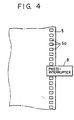
- FIG. 4 illustrates a photo-interrupter for detecting a moving speed of the recording medium.
- recording electrodes 1 apply a charge to particles of a developer in accordance with image information.
- the recording electrodes 1 are densely mounted on a projection 3a provided on the outer circumferential surface of a nonmagnetic cylinder 3, serving as developer supply means for supplying a conductive magnetic developer (hereinafter termed "toner") having a volume resistivity of 103 - 109 ⁇ .cm and a particle size of about 8 ⁇ m - 15 ⁇ m, along the direction of the axis.
- toner a conductive magnetic developer
- the recording electrodes 1 are connected to driving devices 1b provided on a substrata or substratum 1a.
- Recording units 1c, which contribute to recording, of the respective recording electrodes 1 are arranged on the projection 3a.
- a plurality of holes 1d are provided on the substrate 1a along the direction of the axis of the nonmagnetic cylinder 3. These holes 1d are configured so that the toner 2 moved on the outer circumference of the nonmagnetic cylinder 3 passes in the direction of arrow A and reaches the recording units 1c.
- a flexible printed circuit board is used as the substrate 1a.
- VFD drivers (MSG1163 made by Oki Electric Industry Company, Limited) are used as the driving devices 1b.
- a rotating magnet 4 is coaxially mounted on the nonmagnetic cylinder 3.
- the toner 2 is adhered to and moved on the outer circumferential surface of the nonmagnetic cylinder 3 by a magnetic field generated by the rotating magnet 4.
- the recording sheet 5 is mounted between a tension roller 6a and a driving roller 6b, serving as moving means, which are disposed at upper and lower positions to make a pair.
- the driving roller 6b is rotatably driven by a driving motor 7 shown in FIG. 5 so as to move the recording sheet 5 in the direction of arrow B shown in FIG. 1.
- the recording sheet 5 is configured by a base material 5d made of a plastic resin, such as polyethylene terephthalate, polyethylene, polypropylene or the like, a conductive layer 5c about 80 nm - 100 nm (800 ⁇ - 1000 ⁇ ) thick made by depositing aluminum or ITO (an oxide of indium and tin) on the base material 5d in vacuum for providing a conductive property, a colored layer 5b about 5 - 30 ⁇ m thick having a volume resistivity of 100 - 107 ⁇ ⁇ cm, made of a colored inorganic substance and a binder (a plastic resin, such as acrylic resin), and a surface layer 5a about 1 - 20 ⁇ m thick having a volume resistivity of 107 - 1016 ⁇ ⁇ cm, made of transparent materials comprising principally butyl resin or urethane resin.
- a plastic resin such as polyethylene terephthalate, polyethylene, polypropylene or the like
- a conductive layer 5c about
- the surface layer 5a and the colored layer 5b are electrically insulated from each other.
- An inorganic substance such as titanium dioxide (TiO2), aluminum oxide (Al2O3) or the like, is used for the colored layer 5b in order to provide a white base color for the picture surface.
- holes 5a are provided at a side end portion of the recording sheet 5 at a constant interval.
- a photo-interrupter 8 for detecting the moving speed of the recording sheet 5 is provided over the holes 5a. When the recording sheet 5 starts running, the photo-interrupter 8 outputs pulses in accordance with the moving speed of the holes 5a.
- FIGS. 4, 5, 9 and 11 Each of the elements shown in block outline in FIGS. 4, 5, 9 and 11 is well known per se and its specific type or construction is not critical to carrying out the invention or to a disclosure of the best mode for carrying out the invention.
- an image display portion 9 is used for displaying an image formed on the recording sheet 5 to an observer.
- a cleaning member 10 is mounted on a supporting member 11a of a back plate 11 of the main body of the apparatus.
- a nonmagnetic member 12 for supporting the recording sheet 5 is disposed facing the cleaning member 10. There is also shown a magnet 13.
- the toner 2 adhered to and moved on the outer circumference of the nonmagnetic cylinder 3 by the rotating magnet 4 passese through the holes 1d on the substrate 1a and is moved onto the recording electrodes 1.
- the toner 2 adheres to the recording sheet 5, and thus an image can be formed.
- Particles of the toner 2 which have not contributed to image formation on the recording electrodes 1 drop from the projection 3a of the nonmagnetic cylinder 3, and so do not influence the image formed on the recording sheet 5.
- the recording sheet 5 is moved in the direction of arrow B shown in FIG. 1 with a speed of 30 - 500 mm/sec by rotation of the driving roller 6b, and the image formed on the recording sheet 5 is displayed when the image passes through the image display portion 9.
- the toner 2 adhered to the recording sheet 5 passing through the image display portion 9 is removed by the cleaning member 10.
- the removed particles of the toner 2 drop onto the nonmagnetic cylinder 3 and are moved again to be used for the next recording.
- FIG. 5 is a block diagram of the image forming apparatus including a control system.
- a control substrate 14 controls a recording operation for the recording sheet 5 using a recording start signal 15 from the outside.
- the control substrate 14 outputs read pulse signals for a page memory 16, and speed control signals for a motor driver 17 which controls the driving speed of the driving motor 7.
- the page memory 16 stores image information to be recorded on the recording sheet 5.
- the page memory 16 applies signal voltages to the recording electrodes 1 in accordance with image data for one scanning line.
- step S1 when a recording start signal 15 has been input, the control substrate 14 drives the driving motor 7 by the motor driver 17.
- step S2 it is determined whether or not a pulse signal has been input from the photo-interrupter 8. If the determination is affirmative, the process proceeds to step S3, where the control substrate 14 outputs a memory read pulse to the page memory 16 in accordance wih the input pulse.
- the page memory 16 applies signal voltages corresponding to image data for one scannng line to the recording electrodes 1 to form an image.
- control substrate 14 counts the number of pulses output from the photo-interrupter 8.
- the process proceeds to step S4, where the number of pulses or the number of lines for one page is counted, and it is determined whether or not the driving motor 7 is to be decelerated. Whether or not the above-described count number is within the deceleration area for the driving motor 7 is determined so that the page memory 16 is vacant when the driving motor 7 stops.
- step S5 the rotating speed of the driving motor 7 is decelerated by the motor driver 17.
- step S6 it is determined whether or not the control substrate 14 has output memory read pulses corresponding to the number of scanning lines for one page to the page memory 16. If the determination is affirmative, the process proceeds to step S7, where the rotation of the driving motor 7 is stopped. If the result of determination is negative, the operation from step S2 to step S5 is repeated.
- step S4 When the count number has not reached the deceleration area for the driving motor 7 at step S4, the recording sheet 5 is moved at a recording speed to form an image, and the process proceeds to step S6, where the same operation is repeated.
- Symbol "a” represents a motor control signal for driving the driving motor 7.
- a motor speed control signal b for controlling the rotating speed of the driving motor 7 a high level sets the moving speed of the recording sheet 5 to a predetermined recording speed, and a low level sets the rotating speed of the driving motor 7 to a decelerated speed for stopping the driving motor 7 via the motor driver 17.
- Symbol c represents an output waveform from the photointerrupter 8
- symbol d represents memory read pulses output from the control substrate 14 to the page memory 16.
- the control substrate 14 controls the display device so that image data for one scanning line is read from the page memory 16 in accordance with an absolute position signal of the recording sheet 5, that is, a pulse output from the photo-interrupter 8.
- an absolute position signal of the recording sheet 5 that is, a pulse output from the photo-interrupter 8.
- a signal voltage corresponding to image information for one picture element with respect to the direction of movement of the recording sheet 5 is applied to the corresponding recording electrode 1 in accordance with the moving speed of the recording sheet 5.
- the moving speed of the recording sheet 5 is detected by pulse signals from the photo-interrupter 8 using the holes 5a provided at a side end portion of the recording sheet 5.
- an encoder 18 may be mounted on the tension roller 6a, and the moving speed of the recording sheet 5 may be detected by a photointerrupter 8.
- the encoder 18 may be detachably mounted. If an encoder 18 having a large number of holes is used, a high-density, i.e., high-resolution image in the direction of movement of the recording sheet 5 may be formed. If an encoder 18 having a small number of holes is used, a low-resolution image may be formed. Accordingly, it is possible to form an image with the desired resolution.
- the visible image forming means conventional means, wherein an electrostatic latent image is formed using electrostatic electrode needles and the latent image is developed by toner, may also be used.
Description
- This invention relates to an image display device for forming a visible image for display on a recording medium.
- Various kinds of devices for forming a visible image for display in accordance with image information have been developed. One such device uses conductive magnetic toner which serves as a fine-particle developer. The toner is electrostatically applied onto a recording medium, and the resultant image is displayed.
- A method has, for example, been proposed in Japanese Patent Application No. 49-44336 (1974) (corresponding to U.S. Patent No. 3,816,840). According to this method, as shown in FIG. 10, conductive
magnetic toner 51 adhered to the outer circumference of anonmagnetic cylinder 50 is moved by a magnetic field generated by a rotatingmagnet 52 provided coaxially with thenonmagnetic cylinder 50. Thetoner 51 is passed throughrecording electrodes 50a which are densely arranged along the direction of the axis on the outer circumferential surface of thenonmagnetic cylinder 50. When thetoner 51 physically contacts arecording medium 53, which comprises an insulating layer 53a laminated on a conductive layer (cylinder) 53b provided close to thenonmagnetic cylinder 50, voltage is applied to therecording electrodes 50a from a power supply unit 54. By applying a voltage between therecording electrodes 50a and theconductive layer 53b of therecording medium 53 in accordance with image information and thereby injecting electric charges from therecording electrodes 50a into particles of thetoner 51, the particles of thetoner 51 electrostatically adhere to the insulating layer 53a of therecording medium 53, thus forming an image. - In an image forming device for display to which the above-described image forming method is applied, as shown in FIG. 11, the
toner 51 is moved to therecording electrodes 50a by rotation of a magnetic roller (not shown), and particles of thetoner 51 adhere or do not adhere to therecording medium 53, which is moved by a driving movingroller 55a and a drivenmoving roller 55b, in accordance with signal voltages from therecording electrodes 50a, thus forming an image. - The driving moving
roller 55a is driven by a drivingmotor 56 whose speed is controlled by acontrol unit 58 via amotor driver 57. Anencoder 59 detects the moving speed of therecording medium 53. Apage memory 60 stores image information. - FIG. 12 is a timing chart corresponding to a control sequence performed by the
control unit 58. Symbol "a" represents a motor control signal. In a motor speed control signal b, a high level corresponds to the moving speed of therecording medium 53 to perform recording, and a low level corresponds to a reduced moving speed. Symbol c represents an output waveform of theencoder 59, and symbol d represents memory read pulses to be input to thepage memory 60. - FIG. 13 is a timing chart when image data are output from the
page memory 60 to therecording electrodes 50a. - When a memory read pulse e has been input to the
page memory 60, a data enable signal f for requesting the output of image data, a clock signal g for transmitting image data for one line, image data h, and a strobed pulse i for applying the image data h to therecording electrodes 50a are output. - That is, by outputting the strobe pulse i to the
recording electrodes 50a with a constant period while moving therecording medium 53 at a constant speed, an image can be formed on therecording medium 53 for every line with a constant interval. - However, in the above-described configuration, as shown in the timing charts of FIGS. 12 and 13, an image forming operation is started by inputting the memory read pulse e to the
page memory 60 after the moving speed of therecording medium 53 has become constant. Accordingly, as shown in FIGS. 14 (a) and 14(b), an image forming area is smaller than a display area of therecording medium 53, thus decreasing the efficiency of the use of the display area. - As shown in FIG. 14(a), the
recording medium 53 may have connectingportions 53c of recording media on which a recording image cannot be formed. In such a case, the most efficient use of the image forming area can be realized by aligning the connectingportion 53c to face therecording electrodes 50a and starting recording from that position. However, even if such approach is taken, it is impossible to prevent the image forming area from being narrow. The same problem is present even in a recording medium not having areas on which an image cannot be recorded as described above, and in a recording medium which has a predetermined specific position to start recording or stop the recording medium. - US-A-4683380 discloses a photoelectric perforation sensor for detecting perforations in a moving web. The sensor comprises two photodiodes which lie in the direction of web travel. The circuit for detecting the perforation includes a comparator circuit for comparing the outputs of the photodiodes with each other. Circuitry is provided which causes the system to shut down when an insufficient amount of light is received by the photodiodes.
- DE-A-3435810 discloses an image display apparatus which inputs image information and displays it on a large display surface. The apparatus comprises a photosensitive material belt which is arranged to be driven relative to a display section. The joint of the belt is prevented from apearing in the display section.
- EP-A-0342798 discloses an image forming apparatus including a group of recording electrodes arranged in a direction transverse to the movement of a recording medium.
- US-A-4096487 discloses a recording apparatus in which a photosensitive record sheet is drawn past the face of a cathode ray tube. Means are provided for preventing the recording of an image on the record sheet during acceleration or deceleration of the record sheet relative to the cathode ray tube.
- It is an object of the present invention to solve the above-described problems of the related art discussed above.
- It is another object of the present invention to provide an efficient display device.
- It is still another object of the present invention to provide a display device which can shorten recording time and can be made small in size without being restricted by a recording medium, and furthermore can be made under unstable recording speed.
- In accordance with a first aspect of the present invention there is provided an image display device comprising: moving means for supporting a belt-like recording medium such that the medium is endlessly movable in a moving direction; driving means for driving said moving means so as to move the recording medium; recording means for forming a visible image on the recording medium in a main scanning direction when the recording medium is moving, with the main scanning direction being transverse to the moving direction; said device being characterised by: moving speed detection means for detecting whether the movement of the recording medium is in a first phase of acceleration speed from a first stop position, a second phase of constant speed or a third phase of deceleration to a second stop position; control means for driving said recording means during the times when the first, second and third phases of moving speed of the recording medium are detected by said moving speed detection means; and a case for housing the recording medium, said case having an optical opening for viewing the image.
- In accordance with a second aspect of the present invention there is provided an image display method comprising the steps of: supporting a belt-like recording medium such that the medium is endlessly movable in a moving direction; moving the recording medium; forming a visible image on the recording medium in a main scanning direction when the recording medium is moving, with the main scanning direction being transverse to the moving direction; said method being characterised by the further steps of: detecting whether the movement of the recording medium is in a first phase of acceleration speed from a first stop position, a second phase of constant speed or a third phase of deceleration to a second stop position; controlling the forming of a visible image of the recording medium during the times when the first, second and third phases of moving speed of the recording medium are detected by said moving speed detection means; and housing the recording medium in a case, said case having an optical opening for viewing the image.
-
- FIG 1 is a cross-sectional view illustrating the schematic configuration of an image forming apparatus;
- FIG 2 is a perspective view illustrating recording electrodes;
- FIG 3 is a partially-enlarged cross-sectional view of a recording medium;
- FIG 4 is a diagram illustrating a photo-interrupter for detecting a moving speed of the recording medium;
- FIG. 5 is a block diagram of the image forming apparatus including a control system;
- FIG. 6 is a flowchart showing a control operation;
- FIG. 7 is a timing chart of the control operation;
- FIGS. 8(a) and 8(b) illustrate an image forming area;
- FIG. 9 is a block diagram of an image forming apparatus according to another embodiment;
- FIG. 10 illustrates the image forming principle of the apparatus of the embodiments;
- FIG. 11 is a block diagram of a control unit when forming an image;
- FIGS. 12 and 13 are timing charts of signals when operating the unit shown in FIG. 11;
- FIG. 14(a) is a perspective view of a conventional recording medium; and
- FIG. 14(b) is a graph showing a relationship between the moving speed and recording time of the recording medium.
- An explanation will now be provided of an image forming apparatus according to a preferred embodiment of the present invention with reference to the drawings.
- FIG. 1 is a cross-sectional view illustrating the schematic configuration of the image forming apparatus. FIG. 2 is a perspective view illustrating recording electrodes. FIG. 3 is a partially-enlarged cross-sectional view of a recording medium. FIG. 4 illustrates a photo-interrupter for detecting a moving speed of the recording medium.
- First, an explanation will be provided of the schematic configuration of the image forming appartus with reference to FIGS. 1 through 4.
- In FIG. 1,
recording electrodes 1 apply a charge to particles of a developer in accordance with image information. As shown in FIG. 2, therecording electrodes 1 are densely mounted on aprojection 3a provided on the outer circumferential surface of anonmagnetic cylinder 3, serving as developer supply means for supplying a conductive magnetic developer (hereinafter termed "toner") having a volume resistivity of 10³ - 10⁹ Ω .cm and a particle size of about 8 µm - 15 µm, along the direction of the axis. - The
recording electrodes 1 are connected to drivingdevices 1b provided on a substrata orsubstratum 1a. Recording units 1c, which contribute to recording, of therespective recording electrodes 1 are arranged on theprojection 3a. A plurality ofholes 1d are provided on thesubstrate 1a along the direction of the axis of thenonmagnetic cylinder 3. Theseholes 1d are configured so that thetoner 2 moved on the outer circumference of thenonmagnetic cylinder 3 passes in the direction of arrow A and reaches the recording units 1c. A flexible printed circuit board is used as thesubstrate 1a. VFD drivers (MSG1163 made by Oki Electric Industry Company, Limited) are used as thedriving devices 1b. - As shown in FIG. 1, a rotating magnet 4 is coaxially mounted on the
nonmagnetic cylinder 3. Thetoner 2 is adhered to and moved on the outer circumferential surface of thenonmagnetic cylinder 3 by a magnetic field generated by the rotating magnet 4. - An endless-belt-
like recording sheet 5, serving as a recording medium for forming an image by applying thetoner 2 thereon, is disposed so that part of therecording sheet 5 is close to therecording electrodes 1. Therecording sheet 5 is mounted between atension roller 6a and a drivingroller 6b, serving as moving means, which are disposed at upper and lower positions to make a pair. The drivingroller 6b is rotatably driven by a drivingmotor 7 shown in FIG. 5 so as to move therecording sheet 5 in the direction of arrow B shown in FIG. 1. - As shown in FIG. 3, the
recording sheet 5 is configured by abase material 5d made of a plastic resin, such as polyethylene terephthalate, polyethylene, polypropylene or the like, aconductive layer 5c about 80 nm - 100 nm (800 Å - 1000 Å) thick made by depositing aluminum or ITO (an oxide of indium and tin) on thebase material 5d in vacuum for providing a conductive property, acolored layer 5b about 5 - 30 µm thick having a volume resistivity of 10⁰ - 10⁷ Ω ·cm, made of a colored inorganic substance and a binder (a plastic resin, such as acrylic resin), and asurface layer 5a about 1 - 20 µm thick having a volume resistivity of 10⁷ - 10¹⁶ Ω ·cm, made of transparent materials comprising principally butyl resin or urethane resin. - The
surface layer 5a and thecolored layer 5b are electrically insulated from each other. An inorganic substance, such as titanium dioxide (TiO₂), aluminum oxide (Al₂O₃) or the like, is used for thecolored layer 5b in order to provide a white base color for the picture surface. - As shown in FIG. 4,
holes 5a are provided at a side end portion of therecording sheet 5 at a constant interval. A photo-interrupter 8 for detecting the moving speed of therecording sheet 5 is provided over theholes 5a. When therecording sheet 5 starts running, the photo-interrupter 8 outputs pulses in accordance with the moving speed of theholes 5a. - Each of the elements shown in block outline in FIGS. 4, 5, 9 and 11 is well known per se and its specific type or construction is not critical to carrying out the invention or to a disclosure of the best mode for carrying out the invention.
- Referring again to FIG. 1, an
image display portion 9 is used for displaying an image formed on therecording sheet 5 to an observer. A cleaningmember 10 is mounted on a supportingmember 11a of aback plate 11 of the main body of the apparatus. A material having a volume resistivity of 10⁰ - 10³ Ω ·cm, such as carbon fibers, a soft-type plastic (polyethylene or polypropylene) having a conductive property by forming a composite, urethane rubber, silicone or the like, is used for the cleaningmember 10. Anonmagnetic member 12 for supporting therecording sheet 5 is disposed facing the cleaningmember 10. There is also shown amagnet 13. - The
toner 2 adhered to and moved on the outer circumference of thenonmagnetic cylinder 3 by the rotating magnet 4 passee through theholes 1d on thesubstrate 1a and is moved onto therecording electrodes 1. At that time, by applying voltages of about 20 - 40 V (volts) to therecording electrodes 1 in accordance with image information, thetoner 2 adheres to therecording sheet 5, and thus an image can be formed. Particles of thetoner 2 which have not contributed to image formation on therecording electrodes 1 drop from theprojection 3a of thenonmagnetic cylinder 3, and so do not influence the image formed on therecording sheet 5. - During recording, the
recording sheet 5 is moved in the direction of arrow B shown in FIG. 1 with a speed of 30 - 500 mm/sec by rotation of the drivingroller 6b, and the image formed on therecording sheet 5 is displayed when the image passes through theimage display portion 9. Thetoner 2 adhered to therecording sheet 5 passing through theimage display portion 9 is removed by the cleaningmember 10. The removed particles of thetoner 2 drop onto thenonmagnetic cylinder 3 and are moved again to be used for the next recording. - Next, an explanation will be provided of the timing of the charges to be applied to the
recording electrodes 1 in accordance with the moving speed of therecording sheet 5, and a control means for changing the time of voltage application for one picture element with reference to FIG. 5. FIG. 5 is a block diagram of the image forming apparatus including a control system. - A
control substrate 14 controls a recording operation for therecording sheet 5 using arecording start signal 15 from the outside. Thecontrol substrate 14 outputs read pulse signals for apage memory 16, and speed control signals for amotor driver 17 which controls the driving speed of the drivingmotor 7. - The
page memory 16 stores image information to be recorded on therecording sheet 5. When a read pulse is input from thecontrol substrate 14, thepage memory 16 applies signal voltages to therecording electrodes 1 in accordance with image data for one scanning line. - An explanation will now be provided of a control sequence by the
control substrate 14 with reference to the flowchart shown in FIG. 6. - First, at step S1, when a
recording start signal 15 has been input, thecontrol substrate 14 drives the drivingmotor 7 by themotor driver 17. - At step S2, it is determined whether or not a pulse signal has been input from the photo-
interrupter 8. If the determination is affirmative, the process proceeds to step S3, where thecontrol substrate 14 outputs a memory read pulse to thepage memory 16 in accordance wih the input pulse. When the memory read pulse has been input to thepage memory 16, thepage memory 16 applies signal voltages corresponding to image data for one scannng line to therecording electrodes 1 to form an image. - At the same time, the
control substrate 14 counts the number of pulses output from the photo-interrupter 8. The process proceeds to step S4, where the number of pulses or the number of lines for one page is counted, and it is determined whether or not the drivingmotor 7 is to be decelerated. Whether or not the above-described count number is within the deceleration area for the drivingmotor 7 is determined so that thepage memory 16 is vacant when the drivingmotor 7 stops. - When the count number has reached the deceleration area for the driving
motor 7, the process proceeds to step S5, where the rotating speed of the drivingmotor 7 is decelerated by themotor driver 17. - Next, at step S6, it is determined whether or not the
control substrate 14 has output memory read pulses corresponding to the number of scanning lines for one page to thepage memory 16. If the determination is affirmative, the process proceeds to step S7, where the rotation of the drivingmotor 7 is stopped. If the result of determination is negative, the operation from step S2 to step S5 is repeated. - When the count number has not reached the deceleration area for the driving
motor 7 at step S4, therecording sheet 5 is moved at a recording speed to form an image, and the process proceeds to step S6, where the same operation is repeated. - The timing chart of the above-described control operation is shown in FIG. 7. Symbol "a" represents a motor control signal for driving the driving
motor 7. In a motor speed control signal b for controlling the rotating speed of the drivingmotor 7, a high level sets the moving speed of therecording sheet 5 to a predetermined recording speed, and a low level sets the rotating speed of the drivingmotor 7 to a decelerated speed for stopping the drivingmotor 7 via themotor driver 17. Symbol c represents an output waveform from thephotointerrupter 8, and symbol d represents memory read pulses output from thecontrol substrate 14 to thepage memory 16. - According to the above-described timing chart, the
control substrate 14 controls the display device so that image data for one scanning line is read from thepage memory 16 in accordance with an absolute position signal of therecording sheet 5, that is, a pulse output from the photo-interrupter 8. Hence, when the moving speed of therecording sheet 5 is low, the time of voltage application for every picture element for therecording electrodes 1 is increased. As a result, it is possible to form images with an equal interval with respect to the direction of movement of therecording sheet 5. - According to the above-described configuration, a signal voltage corresponding to image information for one picture element with respect to the direction of movement of the
recording sheet 5 is applied to thecorresponding recording electrode 1 in accordance with the moving speed of therecording sheet 5. Hence, it is possible to eliminate wasteful time which is not related to recording, such as a rise time and a fall time of the drivingmotor 7, and the like, and to reduce an area not forming an image of therecording sheet 5, as shown in FIGS. 8(a) and 8(b). - Accordingly, it is possible to sufficiently provide an image forming area relative to an image display area, and to efficiently use the
recording sheet 5. As result, it is possible to provide a small and low-cost apparatus. - In the foregoing embodiment, the moving speed of the
recording sheet 5 is detected by pulse signals from the photo-interrupter 8 using theholes 5a provided at a side end portion of therecording sheet 5. Alternatively, as shown in FIG. 9, anencoder 18 may be mounted on thetension roller 6a, and the moving speed of therecording sheet 5 may be detected by aphotointerrupter 8. - According to the above-described configuration, the
encoder 18 may be detachably mounted. If anencoder 18 having a large number of holes is used, a high-density, i.e., high-resolution image in the direction of movement of therecording sheet 5 may be formed. If anencoder 18 having a small number of holes is used, a low-resolution image may be formed. Accordingly, it is possible to form an image with the desired resolution. - The same effect may also be obtained if a DC motor having an encoder is used for the driving
motor 7. - As described above, in the foregoing embodiments, by changing the timing of the charges applied to the recording electrodes in accordance with the moving speed og the recording medium, wasteful time which does not contribute to image formation is eliminated. Furthermore, it is possible to reduce the side of the entire apparatus by reducing an area not forming an image in an image display area of the recording medium, and thus shortening the recording medium.
- Accordingly, it is possible to sufficiently provide an image forming area relative to an image display area of the recording medium, and to increase the efficiency of the use of the recording mediums. As a result, it is possible to provide a small and low-cost apparatus.
- The above-described effects are effective for a device where in an image forming area is predetermined as shown in FIG. 14(a), as well as for a device wherein an image forming area is not restricted.
- As the visible image forming means, conventional means, wherein an electrostatic latent image is formed using electrostatic electrode needles and the latent image is developed by toner, may also be used.
Claims (5)
- An image display device, comprising:moving means for supporting a belt-like recording medium (5) such that the medium (5) is endlessly movable in a moving direction (B);driving means (6a, 6b, 7) for driving said moving means so as to move the recording medium;recording means (1,2) for forming a visible image on the recording medium (5) in a main scanning direction when the recording medium (5) is moving, with the main scanning direction being transverse to the moving direction;
said device being characterised by:moving speed detection means (5a, 8) for detecting whether the movement of the recording medium (5) is in a first phase of acceleration speed from a first stop position, a second phase of constant speed or a third phase of deceleration to a second stop position;control means (14) for driving said recording means (1,2) during the times when the first, second and third phases of moving speed of the recording medium (5) are detected by said moving speed detection means (5a, 8); anda case for housing the recording medium (5), said case having an optical opening (9) for viewing the image. - An image display device according to claim 1, wherein said control means for driving said recording means (5) is arranged to enable recording during the acceleration phase after the recording medium (5) starts to move.
- An image display device according to claim 1 or 2, wherein said recording means is disposed across the recording medium (5), and comprises recording electrodes (1) arranged in a main scanning direction transverse to the moving direction of said recording means (1,2) and toner supply means (3) for supplying toner (2) between said recording electrodes (1) and the recording medium (5), the recording means being arranged to form a toner image on the recording medium (5) by the application of signal voltages to said recording electrodes (1) when the recording medium (5) is moving.
- An image display method, comprising the steps of:supporting a belt-like recording medium (5) such that the medium (5) is endlessly movable in a moving direction (B);moving the recording medium;forming a visible image on the recording medium (5) in a main scanning direction when the recording medium (5) is moving, with the main scanning direction being transverse to the moving direction;
said method being characterised by the further steps of:detecting whether the movement of the recording medium (5) is in a first phase of acceleration speed from a first stop position, a second phase of constant speed or a third phase of deceleration to a second stop position;controlling the forming of a visible image of the recording medium (5) during the times when the first, second and third phases of moving speed of the recording medium (5) are detected by said moving speed detection means (5a, 8); andhousing the recording medium (5) in a case, said case having an optical opening (9) for viewing the image. - An image display method according to claim 4, wherein said step of driving said moving means (5) enables recording during the acceleration phase after the recording medium (5) starts to move.
Applications Claiming Priority (2)
| Application Number | Priority Date | Filing Date | Title |
|---|---|---|---|
| JP118720/90 | 1990-05-10 | ||
| JP2118720A JPH0416866A (en) | 1990-05-10 | 1990-05-10 | Image forming device |
Publications (3)
| Publication Number | Publication Date |
|---|---|
| EP0456500A2 EP0456500A2 (en) | 1991-11-13 |
| EP0456500A3 EP0456500A3 (en) | 1992-05-06 |
| EP0456500B1 true EP0456500B1 (en) | 1996-04-10 |
Family
ID=14743418
Family Applications (1)
| Application Number | Title | Priority Date | Filing Date |
|---|---|---|---|
| EP91304197A Expired - Lifetime EP0456500B1 (en) | 1990-05-10 | 1991-05-09 | Image display device |
Country Status (4)
| Country | Link |
|---|---|
| US (1) | US5227814A (en) |
| EP (1) | EP0456500B1 (en) |
| JP (1) | JPH0416866A (en) |
| DE (1) | DE69118579T2 (en) |
Families Citing this family (6)
| Publication number | Priority date | Publication date | Assignee | Title |
|---|---|---|---|---|
| US5867688A (en) * | 1994-02-14 | 1999-02-02 | Reliable Transaction Processing, Inc. | Data acquisition and retrieval system with wireless handheld user interface |
| US5614290A (en) * | 1994-02-28 | 1997-03-25 | Nec Corporation | Method and apparatus for displaying color image |
| JPH11281873A (en) * | 1998-03-31 | 1999-10-15 | Fuji Photo Optical Co Ltd | Lens operating device for camera |
| US6542176B1 (en) * | 2000-11-07 | 2003-04-01 | Hewlett-Packard Development Co., L.P. | Electronic display devices and methods |
| US6396525B1 (en) * | 2000-11-07 | 2002-05-28 | Hewlett-Packard Company | Electronic display devices and methods |
| US7559627B2 (en) * | 2004-03-12 | 2009-07-14 | Infoprint Solutions Company, Llc | Apparatus, system, and method for electrorheological printing |
Citations (2)
| Publication number | Priority date | Publication date | Assignee | Title |
|---|---|---|---|---|
| US4096487A (en) * | 1976-11-19 | 1978-06-20 | Honeywell Inc. | Recording apparatus |
| DE3435810A1 (en) * | 1983-09-29 | 1985-04-18 | Canon K.K., Tokio/Tokyo | IMAGE VISOR |
Family Cites Families (16)
| Publication number | Priority date | Publication date | Assignee | Title |
|---|---|---|---|---|
| US3816840A (en) * | 1973-04-20 | 1974-06-11 | Minnesota Mining & Mfg | Electrographic recording process and apparatus using conductive toner subject to a capacitive force |
| US3914771A (en) * | 1973-11-14 | 1975-10-21 | Minnesota Mining & Mfg | Electrographic recording process and apparatus employing synchronized recording pulses |
| JPS53106126A (en) * | 1977-02-28 | 1978-09-14 | Ricoh Co Ltd | Electrostatic recording and apparatus therefor |
| US4167014A (en) * | 1977-02-25 | 1979-09-04 | International Business Machines Corporation | Circuitry for perfecting ink drop printing at varying carrier velocity |
| US4491855A (en) * | 1981-09-11 | 1985-01-01 | Canon Kabushiki Kaisha | Image recording method and apparatus |
| US4504130A (en) * | 1982-09-27 | 1985-03-12 | Coherent Communications, Inc. | System for recording a time code signal on motion picture film |
| EP0142579B1 (en) * | 1983-11-01 | 1988-05-18 | Agfa-Gevaert N.V. | Recording apparatus |
| JPH0773318B2 (en) * | 1985-03-08 | 1995-08-02 | 株式会社日立製作所 | Image information device |
| JPS61233765A (en) * | 1985-04-10 | 1986-10-18 | Canon Inc | Image forming device |
| JPH0690556B2 (en) * | 1985-06-18 | 1994-11-14 | 富士通株式会社 | Electrophotographic recording device |
| US4683380A (en) * | 1985-11-06 | 1987-07-28 | Eastman Kodak Company | Apparatus and method for detecting a perforation on a web |
| US4837636A (en) * | 1987-10-22 | 1989-06-06 | Xerox Corporation | Motion sensor for sensing the relative position and velocity of a recording member |
| JPH01144256A (en) * | 1987-11-30 | 1989-06-06 | Matsushita Electric Ind Co Ltd | Magnetic tape reproducing device |
| US4835545A (en) * | 1987-11-30 | 1989-05-30 | Printware, Inc. | Modulating laser intensity in a laser printer proportionately to the velocity of the photoconductive media |
| JPH06104368B2 (en) * | 1988-04-23 | 1994-12-21 | キヤノン株式会社 | Electrostatic image forming device |
| US5038158A (en) * | 1989-11-13 | 1991-08-06 | Applied Resources, Inc. | Electromagnetic gray scale printer |
-
1990
- 1990-05-10 JP JP2118720A patent/JPH0416866A/en active Pending
-
1991
- 1991-05-09 EP EP91304197A patent/EP0456500B1/en not_active Expired - Lifetime
- 1991-05-09 DE DE69118579T patent/DE69118579T2/en not_active Expired - Fee Related
- 1991-05-10 US US07/698,142 patent/US5227814A/en not_active Expired - Fee Related
Patent Citations (2)
| Publication number | Priority date | Publication date | Assignee | Title |
|---|---|---|---|---|
| US4096487A (en) * | 1976-11-19 | 1978-06-20 | Honeywell Inc. | Recording apparatus |
| DE3435810A1 (en) * | 1983-09-29 | 1985-04-18 | Canon K.K., Tokio/Tokyo | IMAGE VISOR |
Also Published As
| Publication number | Publication date |
|---|---|
| DE69118579T2 (en) | 1996-09-19 |
| JPH0416866A (en) | 1992-01-21 |
| EP0456500A2 (en) | 1991-11-13 |
| US5227814A (en) | 1993-07-13 |
| DE69118579D1 (en) | 1996-05-15 |
| EP0456500A3 (en) | 1992-05-06 |
Similar Documents
| Publication | Publication Date | Title |
|---|---|---|
| US5157423A (en) | Apparatus for pattern generation on a dielectric substrate | |
| US5121170A (en) | Device for transporting sheet members using an alternating voltage | |
| KR100299640B1 (en) | Electrostatic single-pass printer | |
| US5640189A (en) | Image forming apparatus using an electrode matrix to form a latent image | |
| US4547787A (en) | Image forming apparatus with displaying and printing functions | |
| US6291925B1 (en) | Apparatus and methods for reversible imaging of nonemissive display systems | |
| US4658275A (en) | Image forming apparatus | |
| EP0456500B1 (en) | Image display device | |
| US4757332A (en) | Optically imaged recording apparatus | |
| US5172164A (en) | Image forming apparatus with microcapsules dispersed in the photoconductive member | |
| CN1119710C (en) | Method of controlling charge voltage of apparatus using electrophotographic developing process | |
| CN1179251C (en) | Device and method for reducing reverse transfer of image forming apparatus using electrophotography developing system | |
| US5077566A (en) | Image forming apparatus | |
| US20030011795A1 (en) | Belt control means for an image forming apparatus | |
| EP0844095A2 (en) | Toner projection printer | |
| JP3091083B2 (en) | Image forming device | |
| JP2673581B2 (en) | Image forming device | |
| JPH0658553B2 (en) | Recording device | |
| JPS62164083A (en) | Image display device | |
| JPS6086557A (en) | Image forming method | |
| JPS61193184A (en) | Image display unit | |
| JPH0511543A (en) | Image forming device | |
| JPH0652437B2 (en) | Image recorder | |
| JPH0441826B2 (en) | ||
| JPS6010272A (en) | Electrostatic rear recording device |
Legal Events
| Date | Code | Title | Description |
|---|---|---|---|
| PUAI | Public reference made under article 153(3) epc to a published international application that has entered the european phase |
Free format text: ORIGINAL CODE: 0009012 |
|
| AK | Designated contracting states |
Kind code of ref document: A2 Designated state(s): DE FR GB IT |
|
| PUAL | Search report despatched |
Free format text: ORIGINAL CODE: 0009013 |
|
| AK | Designated contracting states |
Kind code of ref document: A3 Designated state(s): DE FR GB IT |
|
| 17P | Request for examination filed |
Effective date: 19920922 |
|
| 17Q | First examination report despatched |
Effective date: 19940426 |
|
| GRAA | (expected) grant |
Free format text: ORIGINAL CODE: 0009210 |
|
| AK | Designated contracting states |
Kind code of ref document: B1 Designated state(s): DE FR GB IT |
|
| PG25 | Lapsed in a contracting state [announced via postgrant information from national office to epo] |
Ref country code: IT Free format text: LAPSE BECAUSE OF FAILURE TO SUBMIT A TRANSLATION OF THE DESCRIPTION OR TO PAY THE FEE WITHIN THE PRESCRIBED TIME-LIMIT;WARNING: LAPSES OF ITALIAN PATENTS WITH EFFECTIVE DATE BEFORE 2007 MAY HAVE OCCURRED AT ANY TIME BEFORE 2007. THE CORRECT EFFECTIVE DATE MAY BE DIFFERENT FROM THE ONE RECORDED. Effective date: 19960410 Ref country code: FR Effective date: 19960410 |
|
| REF | Corresponds to: |
Ref document number: 69118579 Country of ref document: DE Date of ref document: 19960515 |
|
| EN | Fr: translation not filed | ||
| PLBE | No opposition filed within time limit |
Free format text: ORIGINAL CODE: 0009261 |
|
| STAA | Information on the status of an ep patent application or granted ep patent |
Free format text: STATUS: NO OPPOSITION FILED WITHIN TIME LIMIT |
|
| 26N | No opposition filed | ||
| REG | Reference to a national code |
Ref country code: GB Ref legal event code: IF02 |
|
| PGFP | Annual fee paid to national office [announced via postgrant information from national office to epo] |
Ref country code: GB Payment date: 20040426 Year of fee payment: 14 |
|
| PGFP | Annual fee paid to national office [announced via postgrant information from national office to epo] |
Ref country code: DE Payment date: 20040521 Year of fee payment: 14 |
|
| PG25 | Lapsed in a contracting state [announced via postgrant information from national office to epo] |
Ref country code: GB Free format text: LAPSE BECAUSE OF NON-PAYMENT OF DUE FEES Effective date: 20050509 |
|
| PG25 | Lapsed in a contracting state [announced via postgrant information from national office to epo] |
Ref country code: DE Free format text: LAPSE BECAUSE OF NON-PAYMENT OF DUE FEES Effective date: 20051201 |
|
| GBPC | Gb: european patent ceased through non-payment of renewal fee |
Effective date: 20050509 |