EP0456446A1 - Wärmemotor mit einem Kreisprozess mit isenthalper Druckerhöhung - Google Patents
Wärmemotor mit einem Kreisprozess mit isenthalper Druckerhöhung Download PDFInfo
- Publication number
- EP0456446A1 EP0456446A1 EP91304080A EP91304080A EP0456446A1 EP 0456446 A1 EP0456446 A1 EP 0456446A1 EP 91304080 A EP91304080 A EP 91304080A EP 91304080 A EP91304080 A EP 91304080A EP 0456446 A1 EP0456446 A1 EP 0456446A1
- Authority
- EP
- European Patent Office
- Prior art keywords
- fluid
- pressure
- cycle
- working fluid
- temperature
- Prior art date
- Legal status (The legal status is an assumption and is not a legal conclusion. Google has not performed a legal analysis and makes no representation as to the accuracy of the status listed.)
- Granted
Links
- 238000000034 method Methods 0.000 title claims description 37
- 230000008569 process Effects 0.000 title claims description 33
- 239000012530 fluid Substances 0.000 claims abstract description 134
- 230000008859 change Effects 0.000 claims abstract description 24
- 238000011946 reduction process Methods 0.000 claims description 6
- 230000001447 compensatory effect Effects 0.000 claims 1
- 238000007599 discharging Methods 0.000 abstract description 4
- 238000007906 compression Methods 0.000 description 14
- 238000006073 displacement reaction Methods 0.000 description 14
- 239000007789 gas Substances 0.000 description 14
- 230000006835 compression Effects 0.000 description 12
- 230000007423 decrease Effects 0.000 description 9
- XKRFYHLGVUSROY-UHFFFAOYSA-N Argon Chemical compound [Ar] XKRFYHLGVUSROY-UHFFFAOYSA-N 0.000 description 8
- 238000010586 diagram Methods 0.000 description 6
- 229910052786 argon Inorganic materials 0.000 description 4
- 230000009471 action Effects 0.000 description 2
- 230000000694 effects Effects 0.000 description 2
- 230000009467 reduction Effects 0.000 description 2
- 230000004075 alteration Effects 0.000 description 1
- 239000012080 ambient air Substances 0.000 description 1
- 238000002485 combustion reaction Methods 0.000 description 1
- 230000003247 decreasing effect Effects 0.000 description 1
- 239000000463 material Substances 0.000 description 1
- 239000000203 mixture Substances 0.000 description 1
- 239000008239 natural water Substances 0.000 description 1
- 238000005057 refrigeration Methods 0.000 description 1
- 230000000630 rising effect Effects 0.000 description 1
Images



Classifications
-
- F—MECHANICAL ENGINEERING; LIGHTING; HEATING; WEAPONS; BLASTING
- F02—COMBUSTION ENGINES; HOT-GAS OR COMBUSTION-PRODUCT ENGINE PLANTS
- F02C—GAS-TURBINE PLANTS; AIR INTAKES FOR JET-PROPULSION PLANTS; CONTROLLING FUEL SUPPLY IN AIR-BREATHING JET-PROPULSION PLANTS
- F02C1/00—Gas-turbine plants characterised by the use of hot gases or unheated pressurised gases, as the working fluid
- F02C1/04—Gas-turbine plants characterised by the use of hot gases or unheated pressurised gases, as the working fluid the working fluid being heated indirectly
- F02C1/10—Closed cycles
Definitions
- This invention relates to a heat engine based on an improved cycle in which, of the various phases which comprise the thermodynamically functioning cycle; changes are made in the reduction method of the entropy-reduction phase for the purpose of improving the heat efficiency of the cycle used in a heat engine or cold generating device.
- the operating cycle of internal combustion engines and other types of heat engines is comprised of four changing phases consisting of isothermal changes and adiabatic changes between the high-heat source (temperature T1 (°K)) and the low-heat source (temperature T2 (°K)).
- this invention uses for this entropy-reduction phase a cycle which compresses at constant enthalpy by mechanical work without any accompanying generation of heat; in other words, without the need for the discharge of heat to a low-temperature heat source.
- the heat engine utilizing a cycle having an isenthalpic pressure-increasing phase of this invention is characterized in that, in the entropy-reduction phase of the cycle for changing the state of the working fluid, in order to have at least a part of that phase change at constant enthalpy, a compensating fluid (high-pressure feed) at a pressure higher than that of the cycle working fluid is introduced into the cycle system at the beginning of the isenthalpic change, thus increasing the pressure of the working fluid, and then the entropy of the working fluid is reduced by discharging a part of the working fluid to the outside of the cycle system at the end of the isenthalpic change.
- a compensating fluid high-pressure feed
- high-pressure compensating fluid (hereafter sometimes referred to as high-pressure feed) is at the same time supplied through the compensating fluid passage 7 to the tank 6 at approximately the same temperature and pressure P2 as the fluid inside the tank.
- the conditions inside the cylinder during this changing process can be explained based on the P-V graph in Fig. 2 as a process whereby the pressure of the intake fluid is constant at P1 and the volume increases to V1 and then, through the opening of the valve 4, the volume remains constant and the pressure rises to P2. If the volume inside the cylinder taken up by the intake fluid is V2, the volume taken up by the compensating fluid corresponds to V1 - V2. If the working fluid is a real gas, the higher the pressure and the lower the temperature, the smaller the required volume ratio of compensating fluid, (V1 - V2)/V1. For example, if argon gas at a temperature of 132 K is increased in pressure from 500 kg/cm2 to 1,000 kg/cm2, the required volume ratio would be approximately 13%.
- n is the number of molecules of the working fluid and m is the mass of one of these molecules
- the mass of the intake fluid is n1 m
- the mass of the compensating fluid is n2 m
- the mass of the discharge fluid is n3 m
- n1 m + n2 m n3 m
- n1 + n2 n3.
- cycle process is an adiabatic process in which there is no heat flowing in from or out to the outside, and also because a displacement type compressor 1 is used, kinetic energy can be ignored.
- di1 dU1 + A P1 dV1 + A V1 dP1
- Equation (4) When Equation (4) is integrated from pressures P1 to P2,
- the amount of change ⁇ i1 of the apparent enthalpy of the intake fluid is equivalent to the total enthalpy of the compensating fluid flowing into the system.
- Equation (9) U1 + A P1 V1 + U f + A P2 V f + A P2 V1 - A P1 V1
- Equation (11) U3 + U1 + U f + A P2 V f
- Equation (12) U1 + A P1 V1 + U f + A P2 V f + A P2 V1 - A P1 V1
- Equation (13) indicates the enthalpy of the working fluid discharged to the outside of the system from the isenthalpic pressure-increasing apparatus of this invention.
- U f + A P2 V f is the enthalpy of the compensating fluid which enters the system, and it can be seen from Equation (13) that, through the changing process, this enthalpy remains constant.
- the remaining U1 + A P1 V1 is the enthalpy of the intake fluid flowing into the system, and it too must remain constant throughout the changing process. This verifies that the working fluid taken into the system is isenthalpic and that the pressure changes from P1 to P2.
- Fig. 3 is a sketch of the T s graph of the range in which the temperature rises as a result of the Joule-Thomson effect.
- the working fluid at point (I) which has been taken in from the passage 2 is compressed at constant enthalpy i1, reaches point (II), and the pressure increases from P1 to P2.
- the temperature decreases from T1 to T2.
- This temperature decrease functions as a low-temperature source which primarily maintains the temperature of the low-temperature side of a clockwise cycle.
- Equation (1) U3 + A P2 V2′
- Equation (27) If Equations (1), (25) and (26) are substituted into Equation (27) and the kinetic energy is ignored in the same way as described earlier,
- Equation (28) is substituted into Equation (25) and the kinetic energy is ignored
- the enthalpy of the fluid discharged from the sytem is the sum of the internal energy of the intake fluid, the amount of work of the adiabatic isentropic compression performed by the compressor, and the amount of work of discharging the working fluid after compression.
- this work of the adiabatic isentropic compression is converted into heat, thus causing the enthalpy of the intake fluid to increase.
- This process is indicated by the shift from point (I) to point (II′) in Fig. 3, with the temperature of the fluid increasing from T1 to T2′ and the enthalpy increasing from i1 to i2′.
- FIG. 4 is a system diagram of one embodiment of the heat engine according to this invention.
- a displacement compressor 10 and a tank 11 comprise the essential elements of the isenthalpic pressure-increasing apparatus of this invention.
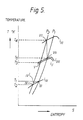
- Fig. 5 shows the T s graph for the cycle process and Fig. 6 is the basic cycle diagram.
- the high-pressure compensating fluid which enters the passage 13 passes through heat exchangers 14 and 15, and undergoes heat exchange with the fluid coming from a compressor 16 and an expander 17 so that its temperature increases at a constant pressure.
- the compensating fluid then passes through a heater 18, where the temperature is further increased by a high-temperature heat source fluid 19 from outside the system, and finally it reaches the expander 17. This process is indicated by points (IV), (V), and (VI) in Fig. 5.
- This high-pressure, high-temperature working fluid performs mechanical work outside the system in the expander 17, and the working fluid itself decreases in pressure and temperature, passes through the heat exchanger 15, undergoes heat exchange with the working fluid from the passage 13, the temperature decreases further, and this fluid is taken into the displacement compressor 10.
- This process is indicated in Fig. 5 by points (VI) and (VII) and points (VII) and (III).
- the compensating fluid needed for the isenthalpic pressure increase is guided from the outlet side of the expander 17 to the compressor 16, where it is compressed at constant entropy, the pressure and temperature increase, and then the fluid is guided to the heater 18.
- This process is indicated by the shift from point (VII) to point (VI) in Fig. 5.
- this fluid is cooled to approximately the same temperature as the working fluid inside the tank 11, it enters the tank 11 as the compensating fluid, and it also enters the displacement compressor 10.
- the piston of the compressor 16 rises slightly earlier than the piston of the displacement compressor 10, performing one compression per cycle and functioning to move the compensating fluid.
- the tank 11 is provided with a refrigeration unit or a cold generating device 21 in order to compensate for this increase.
- the entropy of the working fluid is reduced at constant enthalpy by mechanical work without discharging any heat to the low-temperature side.
- the cycle operate in accordance with the characteristics of the working fluid across an appropriate temperature range below the natural temperature. Taking only the temperature into consideration, it is possible to set the T0 in Equation (30) to an appropriate temperature below the natural temperature, and, if the high-temperature side of the cycle is the same, it is possible for ⁇ c to be closer to 1, thus improving the heat efficiency of the cycle.
- the process from point (a) to point (b) is an isenthalpic change, the temperature remains T0 and does not change.
- working fluid equivalent to the enthalpy (i f ) of the compensating fluid is discharged to the outside of the system (the outside of the cylinder) by the displacement action of the piston.
- the amount of heat applied to the cycle is the area enclosed by points (f), (c), (d), and (e) in Fig. 6, and this is designated Q H .
- the work consumed in the isenthalpic process from point (a) to point (b) is designated W, the corresponding amount of heat is A W.
- ⁇ ⁇ 0.94 i.e. 94% is the theoretical heat efficiency of this heat engine.
Landscapes
- Engineering & Computer Science (AREA)
- Chemical & Material Sciences (AREA)
- Combustion & Propulsion (AREA)
- Mechanical Engineering (AREA)
- General Engineering & Computer Science (AREA)
- Engine Equipment That Uses Special Cycles (AREA)
Applications Claiming Priority (2)
| Application Number | Priority Date | Filing Date | Title |
|---|---|---|---|
| JP11934090A JPH0417703A (ja) | 1990-05-08 | 1990-05-08 | 等エンタルピー昇圧過程を持つサイクルの熱機関 |
| JP119340/90 | 1990-05-08 |
Publications (2)
| Publication Number | Publication Date |
|---|---|
| EP0456446A1 true EP0456446A1 (de) | 1991-11-13 |
| EP0456446B1 EP0456446B1 (de) | 1997-03-05 |
Family
ID=14759064
Family Applications (1)
| Application Number | Title | Priority Date | Filing Date |
|---|---|---|---|
| EP19910304080 Expired - Lifetime EP0456446B1 (de) | 1990-05-08 | 1991-05-07 | Wärmemotor mit einem Kreisprozess mit isenthalper Druckerhöhung |
Country Status (3)
| Country | Link |
|---|---|
| EP (1) | EP0456446B1 (de) |
| JP (1) | JPH0417703A (de) |
| DE (1) | DE69124831D1 (de) |
Families Citing this family (1)
| Publication number | Priority date | Publication date | Assignee | Title |
|---|---|---|---|---|
| JP6295391B1 (ja) * | 2017-10-20 | 2018-03-14 | 一彦 永嶋 | 動力生成システム及び同動力生成システムを用いた発電システム |
Citations (3)
| Publication number | Priority date | Publication date | Assignee | Title |
|---|---|---|---|---|
| US2621481A (en) * | 1946-09-25 | 1952-12-16 | Parsons C A & Co Ltd | Closed cycle air turbine power plant having direct and indirect heat exchangers |
| FR2412692A1 (fr) * | 1977-12-23 | 1979-07-20 | Texaco Development Corp | Procede pour gazeifier du gaz naturel liquefie et produire de l'energie |
| DE3515560A1 (de) * | 1985-04-30 | 1985-10-10 | Genswein, geb.Schmitt, Annemarie, 5160 Düren | Waermekraftmaschine zur nutzung von umgebungswaerme, insbesondere von luftwaerme |
-
1990
- 1990-05-08 JP JP11934090A patent/JPH0417703A/ja active Pending
-
1991
- 1991-05-07 EP EP19910304080 patent/EP0456446B1/de not_active Expired - Lifetime
- 1991-05-07 DE DE69124831T patent/DE69124831D1/de not_active Expired - Lifetime
Patent Citations (3)
| Publication number | Priority date | Publication date | Assignee | Title |
|---|---|---|---|---|
| US2621481A (en) * | 1946-09-25 | 1952-12-16 | Parsons C A & Co Ltd | Closed cycle air turbine power plant having direct and indirect heat exchangers |
| FR2412692A1 (fr) * | 1977-12-23 | 1979-07-20 | Texaco Development Corp | Procede pour gazeifier du gaz naturel liquefie et produire de l'energie |
| DE3515560A1 (de) * | 1985-04-30 | 1985-10-10 | Genswein, geb.Schmitt, Annemarie, 5160 Düren | Waermekraftmaschine zur nutzung von umgebungswaerme, insbesondere von luftwaerme |
Also Published As
| Publication number | Publication date |
|---|---|
| DE69124831D1 (de) | 1997-04-10 |
| EP0456446B1 (de) | 1997-03-05 |
| JPH0417703A (ja) | 1992-01-22 |
Similar Documents
| Publication | Publication Date | Title |
|---|---|---|
| US4267701A (en) | Helium liquefaction plant | |
| US3237847A (en) | Compressor and method | |
| US5209065A (en) | Heat engine utilizing a cycle having an isenthalpic pressure-increasing process | |
| JP2511604B2 (ja) | 寒剤冷凍装置 | |
| KR940000732B1 (ko) | 영구가스 스트림(stream) 액화방법 | |
| KR101980332B1 (ko) | 상변화 웨이브 로터를 사용한 오토-케스케이드 냉동 시스템 | |
| US3812682A (en) | Thermal refrigeration process and apparatus | |
| US4341070A (en) | High thermal efficiency power plant and operating method therefor | |
| EP0456446B1 (de) | Wärmemotor mit einem Kreisprozess mit isenthalper Druckerhöhung | |
| US3636719A (en) | Refrigeration apparatus for developing extremely low temperatures | |
| Rea et al. | The influence of pressure cycling on thermal regenerators | |
| EP2638252B1 (de) | Verfahren zur umwandlung von wärmeenergie aus einer temperaturveränderlichen wärmequelle in mechanische energie | |
| US3803857A (en) | Refrigeration system | |
| Arnaiz Del Pozo et al. | Thermal and exergy efficiency analysis of a solar-driven closed brayton power plant with helium & S-CO2 as working fluids | |
| Haywood | An introduction to Stirling-cycle machines | |
| Kim et al. | A new Ericsson cycle comprising a scroll expander and a scroll compressor for power and refrigeration applications | |
| US4878350A (en) | Pulsation dampening device for super critical fluid expansion engine, hydraulic engine or pump in cryogenic service | |
| Chouder et al. | Dynamic Modeling of a Free Liquid Piston Ericsson Engine (FLPEE) | |
| RU2036394C1 (ru) | Способ получения холода | |
| SU1537980A1 (ru) | Способ производства холода и криогенна установка дл его осуществлени | |
| Bartoli | Gifford McMahon Refrigerating Cycle for Liquefying Small Amounts of Hydrogen: Analysis of the Performances | |
| CN1991155A (zh) | 热气机装置及其制造方法 | |
| RU2158831C1 (ru) | Способ работы теплового двигателя | |
| Subramaniyan et al. | Second law analysis on performance of double stage reciprocating air compressor with inter cooler | |
| Peterson | Thermocompression engine cycle with isothermal expansion |
Legal Events
| Date | Code | Title | Description |
|---|---|---|---|
| PUAI | Public reference made under article 153(3) epc to a published international application that has entered the european phase |
Free format text: ORIGINAL CODE: 0009012 |
|
| AK | Designated contracting states |
Kind code of ref document: A1 Designated state(s): CH DE FR GB IT LI |
|
| 17P | Request for examination filed |
Effective date: 19920313 |
|
| 17Q | First examination report despatched |
Effective date: 19930303 |
|
| GRAG | Despatch of communication of intention to grant |
Free format text: ORIGINAL CODE: EPIDOS AGRA |
|
| GRAH | Despatch of communication of intention to grant a patent |
Free format text: ORIGINAL CODE: EPIDOS IGRA |
|
| GRAH | Despatch of communication of intention to grant a patent |
Free format text: ORIGINAL CODE: EPIDOS IGRA |
|
| GRAA | (expected) grant |
Free format text: ORIGINAL CODE: 0009210 |
|
| AK | Designated contracting states |
Kind code of ref document: B1 Designated state(s): CH DE FR GB IT LI |
|
| PG25 | Lapsed in a contracting state [announced via postgrant information from national office to epo] |
Ref country code: IT Free format text: LAPSE BECAUSE OF FAILURE TO SUBMIT A TRANSLATION OF THE DESCRIPTION OR TO PAY THE FEE WITHIN THE PRE;WARNING: LAPSES OF ITALIAN PATENTS WITH EFFECTIVE DATE BEFORE 2007 MAY HAVE OCCURRED AT ANY TIME BEFORE 2007. THE CORRECT EFFECTIVE DATE MAY BE DIFFERENT FROM THE ONE RECORDED.SCRIBED TIME-LIMIT Effective date: 19970305 Ref country code: LI Effective date: 19970305 Ref country code: CH Effective date: 19970305 |
|
| REG | Reference to a national code |
Ref country code: CH Ref legal event code: EP |
|
| REF | Corresponds to: |
Ref document number: 69124831 Country of ref document: DE Date of ref document: 19970410 |
|
| ET | Fr: translation filed | ||
| PG25 | Lapsed in a contracting state [announced via postgrant information from national office to epo] |
Ref country code: DE Effective date: 19970606 |
|
| REG | Reference to a national code |
Ref country code: CH Ref legal event code: PL |
|
| PLBE | No opposition filed within time limit |
Free format text: ORIGINAL CODE: 0009261 |
|
| STAA | Information on the status of an ep patent application or granted ep patent |
Free format text: STATUS: NO OPPOSITION FILED WITHIN TIME LIMIT |
|
| 26N | No opposition filed | ||
| PGFP | Annual fee paid to national office [announced via postgrant information from national office to epo] |
Ref country code: FR Payment date: 19980511 Year of fee payment: 8 |
|
| PGFP | Annual fee paid to national office [announced via postgrant information from national office to epo] |
Ref country code: GB Payment date: 19990505 Year of fee payment: 9 |
|
| PG25 | Lapsed in a contracting state [announced via postgrant information from national office to epo] |
Ref country code: FR Free format text: LAPSE BECAUSE OF NON-PAYMENT OF DUE FEES Effective date: 20000131 |
|
| REG | Reference to a national code |
Ref country code: FR Ref legal event code: ST |
|
| PG25 | Lapsed in a contracting state [announced via postgrant information from national office to epo] |
Ref country code: GB Free format text: LAPSE BECAUSE OF NON-PAYMENT OF DUE FEES Effective date: 20000507 |
|
| GBPC | Gb: european patent ceased through non-payment of renewal fee |
Effective date: 20000507 |