EP0455575B1 - Shielding overcoat device - Google Patents
Shielding overcoat device Download PDFInfo
- Publication number
- EP0455575B1 EP0455575B1 EP91480060A EP91480060A EP0455575B1 EP 0455575 B1 EP0455575 B1 EP 0455575B1 EP 91480060 A EP91480060 A EP 91480060A EP 91480060 A EP91480060 A EP 91480060A EP 0455575 B1 EP0455575 B1 EP 0455575B1
- Authority
- EP
- European Patent Office
- Prior art keywords
- connector
- shielding
- data connector
- shield
- mating
- Prior art date
- Legal status (The legal status is an assumption and is not a legal conclusion. Google has not performed a legal analysis and makes no representation as to the accuracy of the status listed.)
- Expired - Lifetime
Links
Images


Classifications
-
- H—ELECTRICITY
- H01—ELECTRIC ELEMENTS
- H01R—ELECTRICALLY-CONDUCTIVE CONNECTIONS; STRUCTURAL ASSOCIATIONS OF A PLURALITY OF MUTUALLY-INSULATED ELECTRICAL CONNECTING ELEMENTS; COUPLING DEVICES; CURRENT COLLECTORS
- H01R13/00—Details of coupling devices of the kinds covered by groups H01R12/70 or H01R24/00 - H01R33/00
- H01R13/02—Contact members
- H01R13/28—Contacts for sliding cooperation with identically-shaped contact, e.g. for hermaphroditic coupling devices
-
- H—ELECTRICITY
- H01—ELECTRIC ELEMENTS
- H01R—ELECTRICALLY-CONDUCTIVE CONNECTIONS; STRUCTURAL ASSOCIATIONS OF A PLURALITY OF MUTUALLY-INSULATED ELECTRICAL CONNECTING ELEMENTS; COUPLING DEVICES; CURRENT COLLECTORS
- H01R13/00—Details of coupling devices of the kinds covered by groups H01R12/70 or H01R24/00 - H01R33/00
- H01R13/648—Protective earth or shield arrangements on coupling devices, e.g. anti-static shielding
- H01R13/658—High frequency shielding arrangements, e.g. against EMI [Electro-Magnetic Interference] or EMP [Electro-Magnetic Pulse]
- H01R13/6581—Shield structure
- H01R13/6582—Shield structure with resilient means for engaging mating connector
- H01R13/6583—Shield structure with resilient means for engaging mating connector with separate conductive resilient members between mating shield members
-
- H—ELECTRICITY
- H01—ELECTRIC ELEMENTS
- H01R—ELECTRICALLY-CONDUCTIVE CONNECTIONS; STRUCTURAL ASSOCIATIONS OF A PLURALITY OF MUTUALLY-INSULATED ELECTRICAL CONNECTING ELEMENTS; COUPLING DEVICES; CURRENT COLLECTORS
- H01R13/00—Details of coupling devices of the kinds covered by groups H01R12/70 or H01R24/00 - H01R33/00
- H01R13/648—Protective earth or shield arrangements on coupling devices, e.g. anti-static shielding
- H01R13/658—High frequency shielding arrangements, e.g. against EMI [Electro-Magnetic Interference] or EMP [Electro-Magnetic Pulse]
- H01R13/6591—Specific features or arrangements of connection of shield to conductive members
- H01R13/6592—Specific features or arrangements of connection of shield to conductive members the conductive member being a shielded cable
- H01R13/6593—Specific features or arrangements of connection of shield to conductive members the conductive member being a shielded cable the shield being composed of different pieces
-
- H—ELECTRICITY
- H01—ELECTRIC ELEMENTS
- H01R—ELECTRICALLY-CONDUCTIVE CONNECTIONS; STRUCTURAL ASSOCIATIONS OF A PLURALITY OF MUTUALLY-INSULATED ELECTRICAL CONNECTING ELEMENTS; COUPLING DEVICES; CURRENT COLLECTORS
- H01R13/00—Details of coupling devices of the kinds covered by groups H01R12/70 or H01R24/00 - H01R33/00
- H01R13/62—Means for facilitating engagement or disengagement of coupling parts or for holding them in engagement
- H01R13/627—Snap or like fastening
Definitions
- the present invention relates to electrical connectors in general and in particular to a shielding overcoat device for a data connector used in data communications systems.
- Data connectors are widely used in the communications industry. Usually, data connectors are used to attach data terminal equipment (DTE) to communications highways. DTE is a generic term which may include computers, printers, word processors, displays, etc. The data connectors transmit electrical signals representative of data between the DTE and the communications highway.
- DTE data terminal equipment
- the data connectors transmit electrical signals representative of data between the DTE and the communications highway.
- the governments have set radiation limits above which a product, such as the data connector, should not radiate. Failure to meet the set limits or standard could result in severe penalties.
- each member consists of a plurality of terminals 19 mounted in a terminal block 15.
- the connector consists of identical hermaphroditic mating members.
- the terminals have wire connecting sections and folded resilient contact sections (not shown) for mating with similar folded resilient contact sections of a complimentary mating member.
- the terminal block 15 is mounted in a housing.
- the housing includes a non-conducting lower cover plate 21 which has a wire connecting end aligned with the wire connecting section of the terminals and an open end for mating with a similar lower cover plate of a complementary mating member, aligned with the contact sections of the terminals.
- a non-conducting upper cover member 11 co-acts with the lower non-conducting plate to form a casing about the terminals.
- a conductive upper ground shield 13 and a conductive lower ground shield 14 are provided with interlocking members and are placed inside of the upper and lower cover plates.
- the housing is open at the mating contact sections of the terminals and, except for an opening formed by 51 and 49, is closed at the wire connecting sections of the terminals.
- a shielded cable carrying a plurality of conductors is inserted through the opening. The conductors are each connected to the wire connecting section of a selected terminal and the cable shield 129 firmly connected to the ground shield via elements 65, 70 etc.
- the prior art data connectors work well provided that the data rate is within the range of 4Mb/sec. Whenever the data rate exceeds the 4Mb/sec range, the radiation from the prior art data connector may exceed acceptable radiation limits.
- a principle already disclosed in document "Machine design vol. 58 n° 26, p. 150-152" is to provide a schielding overcoat which can be additionnally fitted over a data connector plug and is connected to the cable shield. A path for grounding between the over coat and the plug is also provided.
- the EMI shielding includes an inner conductive shield interconnected by a conductive member to an outer conductive shield.
- the inner and outer shields encircle the connectors and are coupled to the cable shield. Thus, a low level current conductive path is provided from the connector through the cable shield to ground potential.
- the kit is used to retrofit a data connector one of the above described type an opening is made in the cover of one of the mating members of the hermaphroditic connector.
- the opening provides access to the internal metal casing which shields the terminals.
- a grounding plug is fitted into the opening.
- the plug has a section which firmly contacts the metal casing and a section which forms a seal for the opening and simultaneously contacts a metal sleeve which slides over the connector housing.
- Another metal sleeve is slid over the mating half of the hermaphroditic connector.
- the respective geometries of the sleeves are such that if the connector halves are in mating relationship, the sleeves are placed in an overlapping orientation over the juncture where the cover of the mating conductors meet.
- the shielding overcoat kit of the present invention can be used to in situ retrofitting installed data connectors or it can be included as components of a data connector kit. If included as part of a data connector kit, its installation is affected during the assembling of the data connector.
- Figure 1 is an exploded perspective view of the improved connector according to the teachings of the present invention.
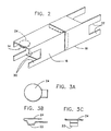
- Figure 2 is a perspective view of the shielding overcoat according to the teachings of the present invention.
- Figure 3 is a sectional view of the grounding plug.
- Figure 4 is a sectional view of one of the two sleeves.
- Figure 5 is a sectional view of the other sleeve.
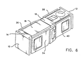
- Figure 6 is a perspective view of the improved connector.
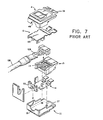
- Figure 7 shows an exploded view of a prior art connector.
- the shielding overcoat device can be used to improve the EMI characteristic of any data connector having internal EMI shield. It works well with the prior art connector and, as such, is described in that environment. However, this should not be construed as a limitation on the scope of the present invention since it is well within the skill of one skilled in the connector art to make changes to the shield overcoat without departing from the scope of the present invention.
- the prior art connector of Figure 7 transmits data at higher data rates without unacceptable EMI problems if covered with the shield overcoat.
- the shield overcoat can be attached to installed connectors without disassembling it or it could be part of a connector kit. It is believed that most of the RF radiation that leaks out of the connector is caused by the disturbance of the electrical characteristics of cable 128 by adding the connector and the necessary altering of the cable shield.
- the cable is a balanced transmission line within a shield 129.
- the lay of the twisted pair conductors is disturbed, the symmetry is altered and the shield is interrupted to provide the mechanical connection function and still achieve the hermaphroditic design required of the connector.
- the balance of the twisted pair cannot be corrected without a major redesign of the connector, but the shield altering can be improved by the external shielding overcoat.
- FIG 1 shows an exploded perspective view of the improved data connector according to the teachings of the present invention.
- the improved data connector includes hermaphroditic connectors 10, 12 and shield overcoat comprised of grounding plug 17, sleeve members 16 and 18.
- the overcoat is assembled to the hermaphroditic connectors by removing dust cover 20 and inserting the ground plug in its place.
- the ground plug is inserted so that contact section 22 is in contact with internal shielding members 13 and 14 (see Fig. 7), respectively.
- the section 24 of the grounding plug contacts the underside of sleeve member 16 when it is mounted to the hermaphroditic connector 10.
- sleeve member 18 is mounted on hermaphroditic connector 12.
- the mating front end of the sleeve members are configured in an overlapping relationship as is shown in Figure 2.
- a conductive path is generated between the overlapping members 16 and 18 through the ground plug 17 to the internal shield 13 and 14 which is connected to cable shield 129 (Fig. 7).
- Figures 3, 4 and 5 show sectional views of the shield overcoat members.
- Figure 3 shows sectional views of the ground plug 17.
- Figure 3A shows a top plan view of the plug.
- Figure 3B shows a front view of the plug with elements 22 and 24.
- Figure 3C shows a side view of the plug.
- Figure 4A shows a top plan view of sleeve 16.
- the mating end 26 has angled members 26A and 26B which are inclined relative to the sides of the sleeve member.
- Figure 4B shows a front elevational view of sleeve member 16 while Figure 4C shows a side elevational view.
- Figure 5 shows sectional views of sleeve member 18.
- Figure 5A shows a top plan view of the sleeve member.
- Figure 5B shows a front elevational view with the mating end 28 having angle members 28A and 28B, respectively.
- Figure 5C shows a side elevational view of sleeve member 18.
- each of the sleeve members has slots such as slot 30 and 32 on opposite sides of each sleeve member. These slots allow each sleeve member to slide over its associated hermaphroditic connector between the connector housing and latching mechanism 34, 36, 38 and 40 (Figs. 1 and 6) respectively.
- the dimensions of the overcoat sleeves can be selected based on the connector to be shielded and will depend on the size of the respective hermaphroditic connector.
- the respective size of the sleeve should be of different geometries so that one can slide over the other to provide the above described overlapping relationship at the mating ends.
- the length of the sleeve measured along respective hermaphroditic connector is approximately 1.50" and the thickness is between .010 and .015 inches.
- the material for the overcoat can be plated steel or any other conductive metal.
- Figure 6 shows a pictorial view of the improved mated connectors 10 and 12 with overcoat members 16 and 18 and ground plug 17.
- the shield can be slipped onto a connector without disassembly, even if it is mounted in a distribution panel (not shown).
- the external surface of the shield occupies a perimeter smaller than that of the connector's exterior dimensions, thereby allowing the shield to be slipped into place without disturbing the mounting of the connector.
- the shield covers the contact and inter-contact area with 360° covering that is connected to the cable system ground by means of ground plug 17.
- the dust cover 20 and one of the mating connectors is removed and the grounding plug substituted in its place.
- the strap on the underside of the plug makes contact with the connector ground plane and the top of the plug makes contact with the overcoat that is slipped over the connector.
- the improved connector with inner and outer shield provides a connector which transmits data at very high rate yet still meets the EMI requirements.
Description
- The present invention relates to electrical connectors in general and in particular to a shielding overcoat device for a data connector used in data communications systems.
- Electrical connectors, hereinafter referred to as data connectors, are widely used in the communications industry. Usually, data connectors are used to attach data terminal equipment (DTE) to communications highways. DTE is a generic term which may include computers, printers, word processors, displays, etc. The data connectors transmit electrical signals representative of data between the DTE and the communications highway. In order to control radiation emission, the governments have set radiation limits above which a product, such as the data connector, should not radiate. Failure to meet the set limits or standard could result in severe penalties.
- U. S. patent 4,501,459 (Re. 32,760) and EP patent 0112711 describe each a prior art data connector. With reference to figure 7 of the present drawings each member consists of a plurality of
terminals 19 mounted in aterminal block 15. The connector consists of identical hermaphroditic mating members. The terminals have wire connecting sections and folded resilient contact sections (not shown) for mating with similar folded resilient contact sections of a complimentary mating member. Theterminal block 15 is mounted in a housing. The housing includes a non-conductinglower cover plate 21 which has a wire connecting end aligned with the wire connecting section of the terminals and an open end for mating with a similar lower cover plate of a complementary mating member, aligned with the contact sections of the terminals. A non-conducting upper cover member 11 co-acts with the lower non-conducting plate to form a casing about the terminals. A conductiveupper ground shield 13 and a conductivelower ground shield 14 are provided with interlocking members and are placed inside of the upper and lower cover plates. The housing is open at the mating contact sections of the terminals and, except for an opening formed by 51 and 49, is closed at the wire connecting sections of the terminals. A shielded cable carrying a plurality of conductors is inserted through the opening. The conductors are each connected to the wire connecting section of a selected terminal and thecable shield 129 firmly connected to the ground shield viaelements - For EMI purposes, the prior art data connectors work well provided that the data rate is within the range of 4Mb/sec. Whenever the data rate exceeds the 4Mb/sec range, the radiation from the prior art data connector may exceed acceptable radiation limits.
- A principle already disclosed in document "Machine design vol. 58 n° 26, p. 150-152" is to provide a schielding overcoat which can be additionnally fitted over a data connector plug and is connected to the cable shield. A path for grounding between the over coat and the plug is also provided.
- Using a similar principle, it is a general object of the present invention to provide a data connector which transmits data at a relatively high data rate and has acceptable radiation characteristics.
- It is another object of the present invention to provide a kit which can be used to retrofit prior art data connectors so that the connectors may transmit data at a relatively high data rate, yet still have radiation levels that fall within acceptable limits.
- These and other objects are achieved by providing improved EMI shielding for the data connector. The EMI shielding includes an inner conductive shield interconnected by a conductive member to an outer conductive shield. The inner and outer shields encircle the connectors and are coupled to the cable shield. Thus, a low level current conductive path is provided from the connector through the cable shield to ground potential.
- In particular, if the kit is used to retrofit a data connector one of the above described type an opening is made in the cover of one of the mating members of the hermaphroditic connector. The opening provides access to the internal metal casing which shields the terminals. A grounding plug is fitted into the opening. The plug has a section which firmly contacts the metal casing and a section which forms a seal for the opening and simultaneously contacts a metal sleeve which slides over the connector housing. Another metal sleeve is slid over the mating half of the hermaphroditic connector. The respective geometries of the sleeves are such that if the connector halves are in mating relationship, the sleeves are placed in an overlapping orientation over the juncture where the cover of the mating conductors meet.
- Thus, the shielding overcoat kit of the present invention can be used to in situ retrofitting installed data connectors or it can be included as components of a data connector kit. If included as part of a data connector kit, its installation is affected during the assembling of the data connector.
- An embodiment of the invention will be more fully described now with reference to the accompanying drawings.
- Figure 1 is an exploded perspective view of the improved connector according to the teachings of the present invention.
- Figure 2 is a perspective view of the shielding overcoat according to the teachings of the present invention.
- Figure 3 is a sectional view of the grounding plug.
- Figure 4 is a sectional view of one of the two sleeves.
- Figure 5 is a sectional view of the other sleeve.
- Figure 6 is a perspective view of the improved connector.
- Figure 7 shows an exploded view of a prior art connector.
- The shielding overcoat device can be used to improve the EMI characteristic of any data connector having internal EMI shield. It works well with the prior art connector and, as such, is described in that environment. However, this should not be construed as a limitation on the scope of the present invention since it is well within the skill of one skilled in the connector art to make changes to the shield overcoat without departing from the scope of the present invention.
- The prior art connector of Figure 7 transmits data at higher data rates without unacceptable EMI problems if covered with the shield overcoat. The shield overcoat can be attached to installed connectors without disassembling it or it could be part of a connector kit. It is believed that most of the RF radiation that leaks out of the connector is caused by the disturbance of the electrical characteristics of
cable 128 by adding the connector and the necessary altering of the cable shield. The cable is a balanced transmission line within ashield 129. The lay of the twisted pair conductors is disturbed, the symmetry is altered and the shield is interrupted to provide the mechanical connection function and still achieve the hermaphroditic design required of the connector. The balance of the twisted pair cannot be corrected without a major redesign of the connector, but the shield altering can be improved by the external shielding overcoat. - Figure 1 shows an exploded perspective view of the improved data connector according to the teachings of the present invention. The improved data connector includes
hermaphroditic connectors grounding plug 17,sleeve members dust cover 20 and inserting the ground plug in its place. The ground plug is inserted so thatcontact section 22 is in contact withinternal shielding members 13 and 14 (see Fig. 7), respectively. Thesection 24 of the grounding plug contacts the underside ofsleeve member 16 when it is mounted to thehermaphroditic connector 10. Similarly,sleeve member 18 is mounted onhermaphroditic connector 12. When the connectors are in mating relationship, the mating front end of the sleeve members are configured in an overlapping relationship as is shown in Figure 2. A conductive path is generated between the overlappingmembers ground plug 17 to theinternal shield - Figures 3, 4 and 5 show sectional views of the shield overcoat members. Figure 3 shows sectional views of the
ground plug 17. Figure 3A shows a top plan view of the plug. Figure 3B shows a front view of the plug withelements - Figure 4A shows a top plan view of
sleeve 16. Themating end 26 has angledmembers sleeve member 16 while Figure 4C shows a side elevational view. - Figure 5 shows sectional views of
sleeve member 18. Figure 5A shows a top plan view of the sleeve member. Figure 5B shows a front elevational view with themating end 28 havingangle members sleeve member 18. - With reference to Figure 2, each of the sleeve members has slots such as
slot mechanism - Figure 6 shows a pictorial view of the improved mated
connectors overcoat members ground plug 17. By using a design that places a shield between the connector body and the latching and unlatching operatedarms ground plug 17. Thedust cover 20 and one of the mating connectors is removed and the grounding plug substituted in its place. The strap on the underside of the plug makes contact with the connector ground plane and the top of the plug makes contact with the overcoat that is slipped over the connector. The improved connector with inner and outer shield provides a connector which transmits data at very high rate yet still meets the EMI requirements.
Claims (6)
- A shielding overcoat device for a dataconnector comprising:an insulative support means (15) having a first face for mating with a complementary data connector and a second face for connecting conductors,a plurality of terminals (19) mounted in the insulative support means, said plurality of terminals having wire connecting ends aligned with the second face and mating ends for mating with terminals of a complimentary data connector aligned with the first face,inner ground shield means (13, 14) disposed adjacent to the insulative support means, andinsulative housing means (11, 21) connected to said insulative support means, and being operable for covering and supporting components of said connector,said shielding overcoat device being characterized in that it comprises:an outer conductive sleeve (16) mounted on the insulative housing means, and being operable for contacting a complimentary conductive shield (18) when said connector is in a mated condition; andgrounding means (17) interconnecting the inner grounding shield and the outer conductive sleeve.
- The shielding overcoat device of claim 1 characterized in that said insulating housing means comprises a removable dust cover section and said grounding means (17) having two contact sections:one section (24) in contact with the underside of said outer conductive sleeve, andthe second section (22) replacing said dust cover section when removed and is thus in contact with said inner ground shield members of the data connector.
- The shielding overcoat device of claim 1 or 2 further including a cable (128) connected to the data connector, and having a plurality of conductors one of each conductor being connected to the wire connecting end of a terminal and a shielding braid (129) coupled to said inner ground shield (13, 14).
- The shielding overcoating device of anyone of claims 1 to 3 wherein the approximate thickness of said shell is between 0.245 and 0.381 mm (0.01 and 0.015 inches).
- The shielding overcoat device of anyone of claims 1 to 4 wherein said shell is fabricated from plated steel.
- The shielding overcoat device of anyone of claims 1 to 5 further including:
a second conductive sleeve member for mounting to a second data connector, said first sleeve and said second sleeve being oriented so that selective ends are overlapped if said data connector and complementary data connector are in matting relation.
Applications Claiming Priority (2)
| Application Number | Priority Date | Filing Date | Title |
|---|---|---|---|
| US07/516,412 US5030114A (en) | 1990-04-30 | 1990-04-30 | Shield overcoat |
| US516412 | 1990-04-30 |
Publications (3)
| Publication Number | Publication Date |
|---|---|
| EP0455575A2 EP0455575A2 (en) | 1991-11-06 |
| EP0455575A3 EP0455575A3 (en) | 1992-10-21 |
| EP0455575B1 true EP0455575B1 (en) | 1996-08-28 |
Family
ID=24055464
Family Applications (1)
| Application Number | Title | Priority Date | Filing Date |
|---|---|---|---|
| EP91480060A Expired - Lifetime EP0455575B1 (en) | 1990-04-30 | 1991-03-29 | Shielding overcoat device |
Country Status (4)
| Country | Link |
|---|---|
| US (1) | US5030114A (en) |
| EP (1) | EP0455575B1 (en) |
| JP (1) | JPH0775180B2 (en) |
| DE (1) | DE69121628D1 (en) |
Families Citing this family (10)
| Publication number | Priority date | Publication date | Assignee | Title |
|---|---|---|---|---|
| US5195902A (en) * | 1990-05-11 | 1993-03-23 | Rit-Rad Interconnection Technologies Ltd. | Electrical connector |
| US5518421A (en) * | 1993-01-26 | 1996-05-21 | The Whitaker Corporation | Two piece shell for a connector |
| US5405268A (en) * | 1993-02-04 | 1995-04-11 | Thomas & Betts Corporation | Vertically aligned electrical connector components |
| US5376021A (en) * | 1993-02-05 | 1994-12-27 | Thomas & Betts Corporation | Enhanced performance data connector |
| US5308264A (en) * | 1993-04-15 | 1994-05-03 | United Technologies Corporation | Modular backshell interface system |
| US5593311A (en) * | 1993-07-14 | 1997-01-14 | Thomas & Betts Corporation | Shielded compact data connector |
| US6939173B1 (en) * | 1995-06-12 | 2005-09-06 | Fci Americas Technology, Inc. | Low cross talk and impedance controlled electrical connector with solder masses |
| US6404995B1 (en) * | 1998-04-10 | 2002-06-11 | Canon Kabushiki Kaisha | Image forming apparatus including a unit detachably attachable to the main assembly having a memory and an antenna electrically connected to the memory |
| US8167661B2 (en) | 2008-12-02 | 2012-05-01 | Panduit Corp. | Method and system for improving crosstalk attenuation within a plug/jack connection and between nearby plug/jack combinations |
| EP2290758B1 (en) * | 2009-08-26 | 2016-09-07 | Wieland Electric GmbH | Industry connector |
Family Cites Families (5)
| Publication number | Priority date | Publication date | Assignee | Title |
|---|---|---|---|---|
| GB2098412B (en) * | 1981-05-11 | 1984-08-01 | Trw Carr Ltd | Shielded electrical connectors |
| IE55318B1 (en) * | 1982-12-22 | 1990-08-01 | Amp Inc | Shunt-protected electrical connector |
| US4781623A (en) * | 1984-01-16 | 1988-11-01 | Stewart Stamping Corporation | Shielded plug and jack connector |
| US4759729A (en) * | 1984-11-06 | 1988-07-26 | Adc Telecommunications, Inc. | Electrical connector apparatus |
| US4708412A (en) * | 1986-05-20 | 1987-11-24 | Amp Incorporated | Electrical connector having low inductance shield |
-
1990
- 1990-04-30 US US07/516,412 patent/US5030114A/en not_active Expired - Fee Related
-
1991
- 1991-03-07 JP JP3065353A patent/JPH0775180B2/en not_active Expired - Lifetime
- 1991-03-29 DE DE69121628T patent/DE69121628D1/en not_active Expired - Lifetime
- 1991-03-29 EP EP91480060A patent/EP0455575B1/en not_active Expired - Lifetime
Also Published As
| Publication number | Publication date |
|---|---|
| EP0455575A3 (en) | 1992-10-21 |
| US5030114A (en) | 1991-07-09 |
| EP0455575A2 (en) | 1991-11-06 |
| JPH0773933A (en) | 1995-03-17 |
| JPH0775180B2 (en) | 1995-08-09 |
| DE69121628D1 (en) | 1996-10-02 |
Similar Documents
| Publication | Publication Date | Title |
|---|---|---|
| CA1188381A (en) | Shielded electrical connector | |
| CA1169533A (en) | Shielded assembly having capacitive coupling feature | |
| US4673236A (en) | Connector assembly | |
| JP3018284B2 (en) | Ground shroud assembly for electrical connector | |
| US4619487A (en) | Flat cable connector with grounding clip | |
| KR100280987B1 (en) | Shielded electrical connectors | |
| US5876248A (en) | Matable electrical connectors having signal and power terminals | |
| EP0297699B1 (en) | Flat cable connectors | |
| US4687263A (en) | Shielding kit for electrical connectors terminating multiconductor 360 degree shielded cable | |
| AU678048B2 (en) | Jack module | |
| US7771230B2 (en) | Methods and systems for minimizing alien crosstalk between connectors | |
| EP0002890B1 (en) | Shielded electrical connector | |
| CN107565279A (en) | Electric connector with shared ground shield | |
| US4579415A (en) | Grounding of shielded cables in a plug and receptacle electrical connector | |
| EP0455575B1 (en) | Shielding overcoat device | |
| US5340333A (en) | Shielded modular adapter | |
| US5222898A (en) | Modular cable assembly | |
| US20080032554A1 (en) | Electrical connector assembly with improved covers | |
| US6042398A (en) | Electrical connector having improved grounding arrangement | |
| EP0108477A1 (en) | Keying system for connector families | |
| US7121888B2 (en) | Multiple wire cable connector | |
| KR100585938B1 (en) | Connector having a shell which can readily be fixed to a connector housing | |
| US8079873B2 (en) | LVDS connector | |
| US6106334A (en) | Shielded cable connector | |
| WO2004008582A1 (en) | Multiple wire cable connector |
Legal Events
| Date | Code | Title | Description |
|---|---|---|---|
| PUAI | Public reference made under article 153(3) epc to a published international application that has entered the european phase |
Free format text: ORIGINAL CODE: 0009012 |
|
| AK | Designated contracting states |
Kind code of ref document: A2 Designated state(s): DE FR GB |
|
| 17P | Request for examination filed |
Effective date: 19911219 |
|
| PUAL | Search report despatched |
Free format text: ORIGINAL CODE: 0009013 |
|
| AK | Designated contracting states |
Kind code of ref document: A3 Designated state(s): DE FR GB |
|
| 17Q | First examination report despatched |
Effective date: 19941220 |
|
| GRAH | Despatch of communication of intention to grant a patent |
Free format text: ORIGINAL CODE: EPIDOS IGRA |
|
| GRAH | Despatch of communication of intention to grant a patent |
Free format text: ORIGINAL CODE: EPIDOS IGRA |
|
| GRAA | (expected) grant |
Free format text: ORIGINAL CODE: 0009210 |
|
| AK | Designated contracting states |
Kind code of ref document: B1 Designated state(s): DE FR GB |
|
| PG25 | Lapsed in a contracting state [announced via postgrant information from national office to epo] |
Ref country code: FR Effective date: 19960828 |
|
| REF | Corresponds to: |
Ref document number: 69121628 Country of ref document: DE Date of ref document: 19961002 |
|
| PG25 | Lapsed in a contracting state [announced via postgrant information from national office to epo] |
Ref country code: DE Effective date: 19961129 |
|
| EN | Fr: translation not filed | ||
| PGFP | Annual fee paid to national office [announced via postgrant information from national office to epo] |
Ref country code: GB Payment date: 19970224 Year of fee payment: 7 |
|
| PLBE | No opposition filed within time limit |
Free format text: ORIGINAL CODE: 0009261 |
|
| STAA | Information on the status of an ep patent application or granted ep patent |
Free format text: STATUS: NO OPPOSITION FILED WITHIN TIME LIMIT |
|
| 26N | No opposition filed | ||
| PG25 | Lapsed in a contracting state [announced via postgrant information from national office to epo] |
Ref country code: GB Free format text: LAPSE BECAUSE OF NON-PAYMENT OF DUE FEES Effective date: 19980329 |
|
| GBPC | Gb: european patent ceased through non-payment of renewal fee |
Effective date: 19980329 |