EP0455496B1 - Multilayer discoidal capacitors - Google Patents
Multilayer discoidal capacitors Download PDFInfo
- Publication number
- EP0455496B1 EP0455496B1 EP91303993A EP91303993A EP0455496B1 EP 0455496 B1 EP0455496 B1 EP 0455496B1 EP 91303993 A EP91303993 A EP 91303993A EP 91303993 A EP91303993 A EP 91303993A EP 0455496 B1 EP0455496 B1 EP 0455496B1
- Authority
- EP
- European Patent Office
- Prior art keywords
- dielectric body
- capacitor
- planar electrodes
- electrodes
- discoidal
- Prior art date
- Legal status (The legal status is an assumption and is not a legal conclusion. Google has not performed a legal analysis and makes no representation as to the accuracy of the status listed.)
- Expired - Lifetime
Links
- 239000003990 capacitor Substances 0.000 title claims description 37
- 239000003989 dielectric material Substances 0.000 claims description 7
- 230000002093 peripheral effect Effects 0.000 claims description 7
- 238000001465 metallisation Methods 0.000 claims description 5
- 239000000919 ceramic Substances 0.000 description 4
- 230000005684 electric field Effects 0.000 description 4
- 238000000926 separation method Methods 0.000 description 4
- 238000010276 construction Methods 0.000 description 2
- 230000000694 effects Effects 0.000 description 2
- 238000004519 manufacturing process Methods 0.000 description 2
- 230000015556 catabolic process Effects 0.000 description 1
- 229910010293 ceramic material Inorganic materials 0.000 description 1
- 239000004020 conductor Substances 0.000 description 1
- 239000000463 material Substances 0.000 description 1
- 239000002184 metal Substances 0.000 description 1
- 238000000034 method Methods 0.000 description 1
- 230000001629 suppression Effects 0.000 description 1
Images

Classifications
-
- H—ELECTRICITY
- H01—ELECTRIC ELEMENTS
- H01G—CAPACITORS; CAPACITORS, RECTIFIERS, DETECTORS, SWITCHING DEVICES, LIGHT-SENSITIVE OR TEMPERATURE-SENSITIVE DEVICES OF THE ELECTROLYTIC TYPE
- H01G4/00—Fixed capacitors; Processes of their manufacture
- H01G4/30—Stacked capacitors
Definitions
- the present invention relates to multilayer discoidal capacitors.
- Multilayer discoidal capacitors are used, for example, to suppress electrical interference on signal and power lines.
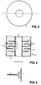
- Each capacitor is constructed from appropriate ceramic materials depending on requirements and has a typical construction as shown in Figs. 3 and 4 of the accompanying drawings, wherein a plurality of first parallel, annular electrodes 53 are embedded within a cylindrical mass of dielectric material 55 and are connected at their inner edges to an inner cylindrical metallization 51, and a plurality of second, annular electrodes 54 are embedded within the dielectric material 55 and are connected at their outer edges to an outer cylindrical metallization 52.
- the total capacitance is the sum of the parallel plate capacitors between each electrode pair.
- C TOT ⁇ ⁇ o ⁇ rA d
- the disc construction is similar to that of multilayer chip capacitors. Their unique application requires the discoidal configuration, firstly, because the central electrode leads to a low inductance path and secondly, for ease of mechanical handling.
- ⁇ r is limited by temperature requirements on the temperature coefficient of capacitance, and unless this is changed, it can be regarded as fixed.
- the separation d is limited by breakdown voltage requirements.
- the area A can only be increased by increasing the number of electrodes, hence making the height of the disc larger, or by reducing the distance from the edge of the electrode to the opposing termination, which increases production alignment problems.
- a multi-layer discoidal capacitor having a plurality of laterally spaced, planar electrodes disposed within a dielectric body.
- a cylindrical electrode extends through the dielectric body perpendicularly to the planar electrodes and is connected to a first terminal of the capacitor.
- a metallisation layer around the outside of the dielectric body is connected to a second terminal of the capacitor.
- a multilayer discoidal capacitor comprising a plurality of laterally spaced, planar electrodes disposed within a dielectric body and at least one cylindrical electrode extending through the dielectric body, perpendicularly to said planar electrodes, and through respective apertures in said electrodes, the cylindrical electrode being connected to a first terminal of the capacitor, wherein the peripheries of said apertures in the planar electrodes terminate within the dielectric body so as to be separated from the cylindrical electrode solely by the dielectric material of the dielectric body, the planar electrodes being connected to a second terminal of the capacitor.
- the or each said cylindrical electrode is formed by metallising the wall of a cylindrical hole in the dielectric body.
- the outer edges of the planar electrodes extend to the peripheral edge of the dielectric body where they are electrically connected together by a metallisation area supplied to said peripheral edge of the body.
- the outer edges of the planar electrodes terminate inwardly of the peripheral edge of the dielectric body and are connected together by one or more conductive pins or vias extending through the dielectric body.
- a multi-layer discoidal capacitor comprising a plurality of laterally spaced, planar electrodes disposed within a dielectric body, at least one cylindrical electrode extending around the dielectric body perpendicularly to said planar electrodes and being connected to a first terminal of the capacitor, and at least one cylindrical electrode which extends through the dielectric body and the planar electrodes and is directly connected to the planar electrodes, said cylindrical electrode being connected to a second terminal of the capacitor, wherein the outer peripheries of the planar electrodes terminate within the dielectric body so as to be separated from the cylindrical electrode solely by the dielectric material of the dielectric body.
- a multilayer discoidal capacitor 50 of the prior art is illustrated in Figs. 3 and 4 and comprises a body of dielectric material 55 of annular cross-section having coaxial inner and outer metallised terminations 51 and 52, respectively, and electrodes in the form of annular discs, the inner electrodes 53 being in electrical contact with the inner termination 51 and the outer electrodes 54 being in contact with the outer termination 52.
- outer and inner terminations are oppositely polarised, then opposing charges will develop on the attached respective outer and inner electrodes. Charge is then distributed over the area of overlap, which is maximised between each pair of inner and outer electrodes. This is illustrated diagrammatically in Fig. 5.
- stray electric fields In order to address the challenge of higher capacitance per unit volume and to give tight control over the spread of capacitance values, use is made in the present invention of "stray" electric fields.
- An example of a “stray” electric field of the type used by the present invention is illustrated in Fig. 5.
- the invention makes use of the "stray" electric field from the edge of conductors rather than trying to achieve a parallel plate capacitor.
- the illustrated embodiment in accordance with the present invention comprises a discoidal body 20 of dielectric (ceramic) material having a plurality of metallic disc electrodes 22 disposed therewithin in spaced parallel planes.
- the ceramic body 20 contains a plurality of through-holes 24 which are coated metallically so as, in effect, to form conductive tubular electrodes 25 which extend perpendicularly to the planes of the metal layers forming the disc electrodes 22.
- the disc electrodes 22 do not extend up to those tubular electrodes 25 but are separated from them by small annular gaps 26. Electrical contact is made to the disc electrodes 22 by metallising the peripheral surface 28 of the ceramic body as shown at 30.
- electrical connection with the disc electrodes 22 can be made by one or more conductive vias or pins 32 which are arranged to extend through the ceramic body 20.
- FIG.2 shows another embodiment of a discoidal capacitor 15 in accordance with the present invention, which has a cylindrical inner termination 16 coaxially disposed within a cylindrical outer termination 17.
- the capacitor 15 further comprises layers of annular discs 18, the inner circumferences of which are in contact with the inner termination 16.
- the diameters of the disc 18 are such that narrow annular gaps 19 arise from the separation between the outer circumferences of each disc 18 and the outer termination 17, the outer termination extending perpendicularly with respect to the discs 18.
Landscapes
- Engineering & Computer Science (AREA)
- Power Engineering (AREA)
- Manufacturing & Machinery (AREA)
- Microelectronics & Electronic Packaging (AREA)
- Fixed Capacitors And Capacitor Manufacturing Machines (AREA)
Description
- The present invention relates to multilayer discoidal capacitors.
- Multilayer discoidal capacitors are used, for example, to suppress electrical interference on signal and power lines. Each capacitor is constructed from appropriate ceramic materials depending on requirements and has a typical construction as shown in Figs. 3 and 4 of the accompanying drawings, wherein a plurality of first parallel,
annular electrodes 53 are embedded within a cylindrical mass ofdielectric material 55 and are connected at their inner edges to an innercylindrical metallization 51, and a plurality of second,annular electrodes 54 are embedded within thedielectric material 55 and are connected at their outer edges to an outercylindrical metallization 52. - The total capacitance is the sum of the parallel plate capacitors between each electrode pair.

where - εo
- = permittivity of free space
- εr
- = dielectric constant
- A
- = area of overlap
- d
- = separation of electrodes
- The disc construction is similar to that of multilayer chip capacitors. Their unique application requires the discoidal configuration, firstly, because the central electrode leads to a low inductance path and secondly, for ease of mechanical handling.
- The requirement for capacitors having a smaller outside diameter offers substantial advantages and is in frequent demand by users. This demand leads to changes in the design of the disc in order to accommodate the same capacitance in a lower volume.
- The three variable parameters in equation (1) are εr, A and d. εr is limited by temperature requirements on the temperature coefficient of capacitance, and unless this is changed, it can be regarded as fixed. The separation d is limited by breakdown voltage requirements. The area A can only be increased by increasing the number of electrodes, hence making the height of the disc larger, or by reducing the distance from the edge of the electrode to the opposing termination, which increases production alignment problems.
- From GB-A- 2046018 there is known a multi-layer discoidal capacitor having a plurality of laterally spaced, planar electrodes disposed within a dielectric body. A cylindrical electrode extends through the dielectric body perpendicularly to the planar electrodes and is connected to a first terminal of the capacitor. A metallisation layer around the outside of the dielectric body is connected to a second terminal of the capacitor. Some of the planar electrodes are connected to the inner cylindrical electrode but not the outer cylindrical electrode and some of the planar electrodes are connected to the outer cylindrical electrode but not the inner cylindrical electrode. Other planar electrodes are connected to neither of the inner and outer cylindrical electrodes.
- It is an object of the present invention to provide improvements in multi-layer discoidal capacitors.
- In accordance with one aspect of the present invention, there is provided a multilayer discoidal capacitor, comprising a plurality of laterally spaced, planar electrodes disposed within a dielectric body and at least one cylindrical electrode extending through the dielectric body, perpendicularly to said planar electrodes, and through respective apertures in said electrodes, the cylindrical electrode being connected to a first terminal of the capacitor, wherein the peripheries of said apertures in the planar electrodes terminate within the dielectric body so as to be separated from the cylindrical electrode solely by the dielectric material of the dielectric body, the planar electrodes being connected to a second terminal of the capacitor.
- Advantageously, the or each said cylindrical electrode is formed by metallising the wall of a cylindrical hole in the dielectric body.
- In one embodiment, the outer edges of the planar electrodes extend to the peripheral edge of the dielectric body where they are electrically connected together by a metallisation area supplied to said peripheral edge of the body.
- In another embodiment the outer edges of the planar electrodes terminate inwardly of the peripheral edge of the dielectric body and are connected together by one or more conductive pins or vias extending through the dielectric body.
- In accordance with a second aspect of the present invention, there is provided a multi-layer discoidal capacitor, comprising a plurality of laterally spaced, planar electrodes disposed within a dielectric body, at least one cylindrical electrode extending around the dielectric body perpendicularly to said planar electrodes and being connected to a first terminal of the capacitor, and at least one cylindrical electrode which extends through the dielectric body and the planar electrodes and is directly connected to the planar electrodes, said cylindrical electrode being connected to a second terminal of the capacitor, wherein the outer peripheries of the planar electrodes terminate within the dielectric body so as to be separated from the cylindrical electrode solely by the dielectric material of the dielectric body.
- By way of example only, specific embodiments of the present invention will now be described with reference to the accompanying drawings, in which:-
- Fig.1a is a longitudinal cross-section of one embodiment of a multilayer discoidal capacitor in accordance with the present invention;
- Fig.1b is a partial longitudinal cross-section of a modified version of a multi-layer discoidal capacitor of Fig.1a;
- Fig.2 is a longitudinal cross-section of a further embodiment of a multi-layer discoidal capacitor in accordance with the invention;
- Fig.3 is a transverse cross-section of a discoidal capacitor of the prior art;
- Fig.4 is a longitudinal cross-section through the line y-y of the capacitor in Fig. 3 of the prior art, and
- Fig.5 shows schematically the production of a "stray" electric field of the type used in the present invention.
- A multilayer
discoidal capacitor 50 of the prior art is illustrated in Figs. 3 and 4 and comprises a body ofdielectric material 55 of annular cross-section having coaxial inner and outermetallised terminations inner electrodes 53 being in electrical contact with theinner termination 51 and theouter electrodes 54 being in contact with theouter termination 52. - If the outer and inner terminations are oppositely polarised, then opposing charges will develop on the attached respective outer and inner electrodes. Charge is then distributed over the area of overlap, which is maximised between each pair of inner and outer electrodes. This is illustrated diagrammatically in Fig. 5.
- In order to address the challenge of higher capacitance per unit volume and to give tight control over the spread of capacitance values, use is made in the present invention of "stray" electric fields. An example of a "stray" electric field of the type used by the present invention is illustrated in Fig. 5. As explained hereinafter, the invention makes use of the "stray" electric field from the edge of conductors rather than trying to achieve a parallel plate capacitor.
- Referring first to Fig.1, the illustrated embodiment in accordance with the present invention comprises a
discoidal body 20 of dielectric (ceramic) material having a plurality ofmetallic disc electrodes 22 disposed therewithin in spaced parallel planes. Theceramic body 20 contains a plurality of through-holes 24 which are coated metallically so as, in effect, to form conductivetubular electrodes 25 which extend perpendicularly to the planes of the metal layers forming thedisc electrodes 22. Thedisc electrodes 22 do not extend up to thosetubular electrodes 25 but are separated from them by smallannular gaps 26. Electrical contact is made to thedisc electrodes 22 by metallising theperipheral surface 28 of the ceramic body as shown at 30. Alternatively, as shown in Fig. 1b, electrical connection with thedisc electrodes 22 can be made by one or more conductive vias orpins 32 which are arranged to extend through theceramic body 20. - Such a capacitor is particularly applicable to situations where space is at a premium, for example in RFI suppression devices. In the latter case, each
tubular electrode 25 would receive a respective through wire (not shown) carrying signal information, the capacitor then acting as a multiway filter. Fig.2 shows another embodiment of adiscoidal capacitor 15 in accordance with the present invention, which has a cylindricalinner termination 16 coaxially disposed within a cylindricalouter termination 17. Thecapacitor 15 further comprises layers ofannular discs 18, the inner circumferences of which are in contact with theinner termination 16. The diameters of thedisc 18 are such that narrowannular gaps 19 arise from the separation between the outer circumferences of eachdisc 18 and theouter termination 17, the outer termination extending perpendicularly with respect to thediscs 18. If theinner termination 16 is then polarised with respect to theouter termination 17, small areas of relatively high charge distribution will develop across thegaps 19. This results because the side edges of the discs have a relatively small surface area in comparison with that of theouter termination 17 to which they are exposed. This arrangement, as illustrated diagrammatically in Fig. 5, allows increased capacitance, independent of axial separation of the individual electrodes. For thicker walled disc electrodes, the effect can be utilised to reduce the impact of process variations and hence produce tight tolerance batches.
Claims (5)
- A multi-layer capacitor, comprising a plurality of axially spaced, planar electrodes (22) disposed within a discoidal dielectric body (20) and at least one tubular electrode (25) extending through the dielectric body (20), perpendicularly to said planar electrodes (22), and throush respective apertures in said electrodes (22), the tubular electrode (25) being connected to a first terminal of the capacitor, characterised in that the peripheries of said apertures in the planar electrodes terminate within the dielectric body (20) so as to be separated from the tubular electrode (25) by the dielectric material of the dielectric body (20), the planar electrodes (22) being connected to a second terminal of the capacitor. (Fig. 1)
- A multi-layer discoidal capacitor as claimed in claim 1 wherein the or each said tubular electrode (25) is formed by metallising the wall of a cylindrical hole in the dielectric body (20).
- A multi-layer discoidal capacitor as claimed in claim 1 or 2, wherein the outer edges of the planar electrodes (22) extend to the peripheral edge of the dielectric body (20) where they are electrically connected together by a metallisation area applied to said peripheral edge of the body (20).
- A multi-layer discoidal capacitor as claimed in claim 1 or 2, wherein the outer edges of the planar electrodes (22) terminate inwardly of the peripheral edge of the dielectric body (20) and are connected together by one or more conductive pins or vias (32) extending through the dielectric body (20).
- A multi-layer capacitor, comprising a plurality of axially spaced, planar electrodes (18) disposed within a discoidal dielectric body, an outer cylindrical termination (17) extending around the dielectric body perpendicularly to said planar electrodes (18) and being connected to a first terminal of the capacitor, and an inner cylindrical termination (16) which extends through the dielectric body and the planar electrodes (18) and is connected to the planar electrodes (18), said inner termination (16) being connected to a second terminal of the capacitor, characterised in that the outer peripheries of the planar electrodes (18) terminate within the dielectric body so as to be separated from the outer termination (17) by the dielectric material of the dielectric body. (Fig. 2)
Applications Claiming Priority (2)
| Application Number | Priority Date | Filing Date | Title |
|---|---|---|---|
| GB9009997 | 1990-05-03 | ||
| GB9009997A GB2243722A (en) | 1990-05-03 | 1990-05-03 | Improvements in multilayer discoidal capacitors |
Publications (3)
| Publication Number | Publication Date |
|---|---|
| EP0455496A2 EP0455496A2 (en) | 1991-11-06 |
| EP0455496A3 EP0455496A3 (en) | 1991-12-27 |
| EP0455496B1 true EP0455496B1 (en) | 1995-08-30 |
Family
ID=10675433
Family Applications (1)
| Application Number | Title | Priority Date | Filing Date |
|---|---|---|---|
| EP91303993A Expired - Lifetime EP0455496B1 (en) | 1990-05-03 | 1991-05-02 | Multilayer discoidal capacitors |
Country Status (4)
| Country | Link |
|---|---|
| US (1) | US5177663A (en) |
| EP (1) | EP0455496B1 (en) |
| DE (1) | DE69112484D1 (en) |
| GB (1) | GB2243722A (en) |
Families Citing this family (29)
| Publication number | Priority date | Publication date | Assignee | Title |
|---|---|---|---|---|
| US5657199A (en) * | 1992-10-21 | 1997-08-12 | Devoe; Daniel F. | Close physical mounting of leaded amplifier/receivers to through holes in monolithic, buried-substrate, multiple capacitors simultaneous with electrical connection to dual capacitors otherwise transpiring, particularly for hearing aid filters |
| US5817130A (en) * | 1996-05-03 | 1998-10-06 | Sulzer Intermedics Inc. | Implantable cardiac cardioverter/defibrillator with EMI suppression filter with independent ground connection |
| GB9623460D0 (en) * | 1996-11-09 | 1997-01-08 | Oxley Dev Co Ltd | Electronic components incorporating capacitors |
| US5872695A (en) * | 1997-02-26 | 1999-02-16 | International Business Machines Corporation | Integrated electronic components having conductive filled through holes |
| US7336468B2 (en) | 1997-04-08 | 2008-02-26 | X2Y Attenuators, Llc | Arrangement for energy conditioning |
| US7321485B2 (en) | 1997-04-08 | 2008-01-22 | X2Y Attenuators, Llc | Arrangement for energy conditioning |
| US9054094B2 (en) | 1997-04-08 | 2015-06-09 | X2Y Attenuators, Llc | Energy conditioning circuit arrangement for integrated circuit |
| JP2000512810A (en) * | 1997-04-25 | 2000-09-26 | コーニンクレッカ フィリップス エレクトロニクス エヌ ヴィ | Method of manufacturing encapsulated multilayer capacitor and encapsulated multilayer capacitor |
| US6088215A (en) * | 1997-11-03 | 2000-07-11 | Motorola, Inc. | Capacitor and method of manufacture |
| US6542352B1 (en) * | 1997-12-09 | 2003-04-01 | Daniel Devoe | Ceramic chip capacitor of conventional volume and external form having increased capacitance from use of closely spaced interior conductive planes reliably connecting to positionally tolerant exterior pads through multiple redundant vias |
| US6366443B1 (en) * | 1997-12-09 | 2002-04-02 | Daniel Devoe | Ceramic chip capacitor of conventional volume and external form having increased capacitance from use of closely-spaced interior conductive planes reliably connecting to positionally-tolerant exterior pads through multiple redundant vias |
| JP3701138B2 (en) * | 1999-04-23 | 2005-09-28 | 松下電器産業株式会社 | Manufacturing method of electronic parts |
| US6327134B1 (en) * | 1999-10-18 | 2001-12-04 | Murata Manufacturing Co., Ltd. | Multi-layer capacitor, wiring board, and high-frequency circuit |
| US6477032B2 (en) * | 2001-01-31 | 2002-11-05 | Avx Corporation | Low inductance chip with center via contact |
| US6760215B2 (en) * | 2001-05-25 | 2004-07-06 | Daniel F. Devoe | Capacitor with high voltage breakdown threshold |
| US6545854B2 (en) * | 2001-05-25 | 2003-04-08 | Presidio Components, Inc. | Fringe-field non-overlapping-electrodes discoidal feed-through ceramic filter capacitor with high breakdown voltage |
| KR20030062021A (en) * | 2002-01-15 | 2003-07-23 | (주) 래트론 | Manufacturing method of cylindrical ceramic capacitor |
| US7307829B1 (en) * | 2002-05-17 | 2007-12-11 | Daniel Devoe | Integrated broadband ceramic capacitor array |
| US6661639B1 (en) | 2002-07-02 | 2003-12-09 | Presidio Components, Inc. | Single layer capacitor |
| JP2004147332A (en) * | 2002-10-23 | 2004-05-20 | Spectrum Control Inc | Miniaturized filter |
| US6917509B1 (en) | 2002-11-21 | 2005-07-12 | Daniel F. Devoe | Single layer capacitor with dissimilar metallizations |
| US6885539B1 (en) | 2003-12-02 | 2005-04-26 | Presidio Components, Inc. | Single layer capacitor |
| US7265995B2 (en) * | 2003-12-29 | 2007-09-04 | Intel Corporation | Array capacitors with voids to enable a full-grid socket |
| FR2880193A1 (en) * | 2004-12-23 | 2006-06-30 | St Microelectronics Sa | SCHOTTKY DIODE WITH VERTICAL BARRIER |
| US7551963B2 (en) * | 2005-02-01 | 2009-06-23 | Greatbatch Ltd. | Apparatus to improve the high voltage flashover characteristics of EMI feedthrough filters used in active implantable medical devices |
| JP2008537843A (en) | 2005-03-01 | 2008-09-25 | エックストゥーワイ アテニュエイターズ,エルエルシー | Overlapping adjuster inside |
| DE102005016590A1 (en) * | 2005-04-11 | 2006-10-26 | Epcos Ag | Electric multilayer component and method for producing a multilayer component |
| US10102973B2 (en) * | 2014-09-12 | 2018-10-16 | Nanotek Instruments, Inc. | Graphene electrode based ceramic capacitor |
| CN118742986A (en) * | 2022-03-15 | 2024-10-01 | 松下知识产权经营株式会社 | Capacitors and power modules |
Family Cites Families (7)
| Publication number | Priority date | Publication date | Assignee | Title |
|---|---|---|---|---|
| GB1149569A (en) * | 1966-09-01 | 1969-04-23 | Mini Of Technology | Capacitors and methods for their manufacture |
| GB1356213A (en) * | 1972-02-18 | 1974-06-12 | Erie Technological Prod Inc | Capacitors |
| US4047240A (en) * | 1976-06-01 | 1977-09-06 | Victor Insetta | Multiple electrode capacitor assembly |
| US4247881A (en) * | 1979-04-02 | 1981-01-27 | Sprague Electric Company | Discoidal monolithic ceramic capacitor |
| NL7905562A (en) * | 1979-07-17 | 1981-01-20 | Heerens Willem Christiaan | CAPACITIVE METER. |
| JPS6016411A (en) * | 1983-07-08 | 1985-01-28 | 株式会社村田製作所 | Laminated porcelain condenser |
| US4864465A (en) * | 1988-05-10 | 1989-09-05 | The United States Of America | Viad chip capacitor and method for making same |
-
1990
- 1990-05-03 GB GB9009997A patent/GB2243722A/en not_active Withdrawn
-
1991
- 1991-05-02 DE DE69112484T patent/DE69112484D1/en not_active Expired - Lifetime
- 1991-05-02 EP EP91303993A patent/EP0455496B1/en not_active Expired - Lifetime
- 1991-05-03 US US07/695,631 patent/US5177663A/en not_active Expired - Lifetime
Also Published As
| Publication number | Publication date |
|---|---|
| US5177663A (en) | 1993-01-05 |
| EP0455496A2 (en) | 1991-11-06 |
| DE69112484D1 (en) | 1995-10-05 |
| GB2243722A (en) | 1991-11-06 |
| GB9009997D0 (en) | 1990-06-27 |
| EP0455496A3 (en) | 1991-12-27 |
Similar Documents
| Publication | Publication Date | Title |
|---|---|---|
| US5177663A (en) | Multilayer discoidal capacitors | |
| US5602517A (en) | Laminate type LC composite device having coils with opposing directions and adjacent leads | |
| US6545854B2 (en) | Fringe-field non-overlapping-electrodes discoidal feed-through ceramic filter capacitor with high breakdown voltage | |
| US3538464A (en) | Multiple pin connector having ferrite core stacked capacitor filter | |
| JP3106942B2 (en) | LC resonance components | |
| US5751539A (en) | EMI filter for human implantable heart defibrillators and pacemakers | |
| JP3863777B2 (en) | Low-capacity multilayer varistor | |
| US5392019A (en) | Inductance device and manufacturing process thereof | |
| US6563688B2 (en) | Isolating energy conditioning shield assembly | |
| US5153540A (en) | Capacitor array utilizing a substrate and discoidal capacitors | |
| EP0444948A2 (en) | Dielectric resonator and a filter using same | |
| US4556929A (en) | Multi-layer ceramic capacitor | |
| US20040012462A1 (en) | Feed-through filter having improved shielding and mounting functions | |
| US6619763B2 (en) | Feed-through filter capacitor with non-overlapping electrodes | |
| US3808478A (en) | Multiple feed-through capacitor and methods of making | |
| WO2001071908A1 (en) | Isolating energy conditioning shield assembly | |
| EP0123457B1 (en) | Filter connector | |
| CN109935467A (en) | Capacitor assembly | |
| US3721871A (en) | High voltage monolithic ceramic capacitor | |
| EP0607898B1 (en) | Pi signal frequency filter and method of manufacture | |
| JP3019616B2 (en) | Stack-through capacitor array | |
| US5051542A (en) | Low impedance bus bar | |
| US3183419A (en) | Electrical capacitor having an internal rib structure | |
| US5459443A (en) | Planar filter, in particular for multiple-pole plug connectors having a plug and a counterpart plug | |
| US3568109A (en) | Variable or low pass filter |
Legal Events
| Date | Code | Title | Description |
|---|---|---|---|
| PUAI | Public reference made under article 153(3) epc to a published international application that has entered the european phase |
Free format text: ORIGINAL CODE: 0009012 |
|
| AK | Designated contracting states |
Kind code of ref document: A2 Designated state(s): DE FR GB |
|
| PUAL | Search report despatched |
Free format text: ORIGINAL CODE: 0009013 |
|
| AK | Designated contracting states |
Kind code of ref document: A3 Designated state(s): DE FR GB |
|
| 17P | Request for examination filed |
Effective date: 19920624 |
|
| 17Q | First examination report despatched |
Effective date: 19940209 |
|
| GRAA | (expected) grant |
Free format text: ORIGINAL CODE: 0009210 |
|
| AK | Designated contracting states |
Kind code of ref document: B1 Designated state(s): DE FR GB |
|
| PG25 | Lapsed in a contracting state [announced via postgrant information from national office to epo] |
Ref country code: FR Free format text: THE PATENT HAS BEEN ANNULLED BY A DECISION OF A NATIONAL AUTHORITY Effective date: 19950830 |
|
| REF | Corresponds to: |
Ref document number: 69112484 Country of ref document: DE Date of ref document: 19951005 |
|
| PG25 | Lapsed in a contracting state [announced via postgrant information from national office to epo] |
Ref country code: DE Effective date: 19951201 |
|
| EN | Fr: translation not filed | ||
| PLBE | No opposition filed within time limit |
Free format text: ORIGINAL CODE: 0009261 |
|
| STAA | Information on the status of an ep patent application or granted ep patent |
Free format text: STATUS: NO OPPOSITION FILED WITHIN TIME LIMIT |
|
| 26N | No opposition filed | ||
| PGFP | Annual fee paid to national office [announced via postgrant information from national office to epo] |
Ref country code: GB Payment date: 19980423 Year of fee payment: 8 |
|
| PG25 | Lapsed in a contracting state [announced via postgrant information from national office to epo] |
Ref country code: GB Free format text: LAPSE BECAUSE OF NON-PAYMENT OF DUE FEES Effective date: 19990502 |
|
| GBPC | Gb: european patent ceased through non-payment of renewal fee |
Effective date: 19990502 |