EP0455377A1 - Labeling machine and method - Google Patents
Labeling machine and method Download PDFInfo
- Publication number
- EP0455377A1 EP0455377A1 EP91303424A EP91303424A EP0455377A1 EP 0455377 A1 EP0455377 A1 EP 0455377A1 EP 91303424 A EP91303424 A EP 91303424A EP 91303424 A EP91303424 A EP 91303424A EP 0455377 A1 EP0455377 A1 EP 0455377A1
- Authority
- EP
- European Patent Office
- Prior art keywords
- segment
- article
- arcuate surface
- leading
- turret
- Prior art date
- Legal status (The legal status is an assumption and is not a legal conclusion. Google has not performed a legal analysis and makes no representation as to the accuracy of the status listed.)
- Granted
Links
Images
Classifications
-
- B—PERFORMING OPERATIONS; TRANSPORTING
- B65—CONVEYING; PACKING; STORING; HANDLING THIN OR FILAMENTARY MATERIAL
- B65C—LABELLING OR TAGGING MACHINES, APPARATUS, OR PROCESSES
- B65C3/00—Labelling other than flat surfaces
- B65C3/06—Affixing labels to short rigid containers
- B65C3/08—Affixing labels to short rigid containers to container bodies
- B65C3/14—Affixing labels to short rigid containers to container bodies the container being positioned for labelling with its centre-line vertical
- B65C3/16—Affixing labels to short rigid containers to container bodies the container being positioned for labelling with its centre-line vertical by rolling the labels onto cylindrical containers, e.g. bottles
-
- Y—GENERAL TAGGING OF NEW TECHNOLOGICAL DEVELOPMENTS; GENERAL TAGGING OF CROSS-SECTIONAL TECHNOLOGIES SPANNING OVER SEVERAL SECTIONS OF THE IPC; TECHNICAL SUBJECTS COVERED BY FORMER USPC CROSS-REFERENCE ART COLLECTIONS [XRACs] AND DIGESTS
- Y10—TECHNICAL SUBJECTS COVERED BY FORMER USPC
- Y10T—TECHNICAL SUBJECTS COVERED BY FORMER US CLASSIFICATION
- Y10T156/00—Adhesive bonding and miscellaneous chemical manufacture
- Y10T156/17—Surface bonding means and/or assemblymeans with work feeding or handling means
- Y10T156/1702—For plural parts or plural areas of single part
- Y10T156/1744—Means bringing discrete articles into assembled relationship
- Y10T156/1768—Means simultaneously conveying plural articles from a single source and serially presenting them to an assembly station
- Y10T156/1771—Turret or rotary drum-type conveyor
- Y10T156/1773—For flexible sheets
-
- Y—GENERAL TAGGING OF NEW TECHNOLOGICAL DEVELOPMENTS; GENERAL TAGGING OF CROSS-SECTIONAL TECHNOLOGIES SPANNING OVER SEVERAL SECTIONS OF THE IPC; TECHNICAL SUBJECTS COVERED BY FORMER USPC CROSS-REFERENCE ART COLLECTIONS [XRACs] AND DIGESTS
- Y10—TECHNICAL SUBJECTS COVERED BY FORMER USPC
- Y10T—TECHNICAL SUBJECTS COVERED BY FORMER US CLASSIFICATION
- Y10T156/00—Adhesive bonding and miscellaneous chemical manufacture
- Y10T156/17—Surface bonding means and/or assemblymeans with work feeding or handling means
- Y10T156/1702—For plural parts or plural areas of single part
- Y10T156/1744—Means bringing discrete articles into assembled relationship
- Y10T156/1776—Means separating articles from bulk source
- Y10T156/1778—Stacked sheet source
- Y10T156/178—Rotary or pivoted picker
Definitions
- This invention relates to labeling machines of the type in which labels are picked up by a vacuum drum at a label pick up station from a stack of labels or as they are severed from a continuous strip of label stock, and are held on the drum surface by vacuum and transported to a label applying station, and in which containers are picked up at a container pick up station by aligned chucks on a turret and are transported to the label applying station where they contact the leading end of labels (which are released) and are wrapped around the container by spinning motion of the containers and are transported to a container exit station.
- Such unattached or flagging segments of labels are ultimately wrapped around a container, either completely as in full wrap or partially as in what is known as a "spot label".
- the trailing end of the label is adhered to the container by an adhesive in the case of a spot label or it overlaps and is adhered to the leading end of the label by an adhesive in the case of a full wrap.
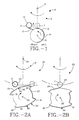
- Figure 1 is a diagrammatic top plan view of a turret type of labeling machine employing a vacuum drum such as described in U.S. Patent 4,108,709 and it is shown at a stage of operation where the leading end of a label has been applied to a container and the label has been partially been wrapped around the container.
- a vacuum drum such as described in U.S. Patent 4,108,709
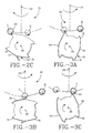
- Figure 2A is a similar view of a turret type of labeling machine in which the vacuum drum is shaped in accordance with the present invention, such view showing the situation at the commencement of labeling of a container when the leading end of the label is applied to the container.
- Figure 2B is similar to Figure 2A but shows the machine at a later stage of operation with the label partially wrapped around the container.
- Figure 2C is a similar view but of the final stage of labeling in which the label has been completely applied to the container and its trailing end laps over the leading end.
- Figures 3A, 3B and 3C are similar to Figures 2A, 2B and 2C, respectively, but show a machine in which the vacuum drum and the turret are rotating in opposite directions, for example one being clockwise and the other counterclockwise.
- a labeling machine is shown diagramatically and is generally designated by the reference numeral 10. It comprises a turret 11 rotating orbitally about a central turret axis 12 and carrying pairs of axially aligned chucks (not shown) such as those shown at 39 and 36 in Figure 2 of U.S. Patent 4,108,709. Each pair of chucks clamps a container such as shown at I by its ends, transports the container to a label pickup station as illustrated by the container I where it picks up the leading end of a label 13 from a rotating vacuum drum 14 which rotates about an axis 15 parallel to the turret axis 12.
- the container with the leading end of a label 13 attached is caused to spin in the direction shown by the arrow, thus wrapping the label around it.
- the turret is provided with means to separate each pair of chucks at a container pickup station to receive a container between them and then to move toward one another to clamp the container between the chucks and to cause the container to spin. It will also be understood that after labeling has been completed the chucks will be separated to allow removal of a labeled container, which is removed from the turret at a container delivery station.
- Container II has moved with the turret away from the vacuum drum and a segment of partially applied label, indicated at 17, is unattached to the container. For a short interval of time the trailing end of the label remains unattached to the vacuum drum but later it is wrapped around the container. If the label is, for example, a limp, plastic label and/or if because of the speed of the machine there are currents of air the unattached portion of the label, particularly when its trailing end leaves the vacuum drum, is subject to random, chaotic motion which will result in faulty labeling.
- a turret/vacuum drum labeling machine is shown diagrammatically and is designated generally by the numeral 20. It includes a turret 21 rotating about a turret axis 22. Containers I and II are shown, container I being shown at the position of commencement of labeling. A vacuum drum is shown at 23 which transports and applies labels 24 to the containers.
- the vacuum drum 23 rotates about axis 25 parallel to the turret axis 22.
- the drum 23 is shown with two sections or pads 26 separated by segments 27. There may, however, be only one pad 26 and one segment 27 or there may be more than two pads 26 and more than two segments 27.
- the pads 26 are preferably made of a hard rubber material of a type commonly used in the construction of vacuum drums for labeling machines and they are perforated to apply vacuum from the vacuum system of the machine for the purpose of holding labels on the surface of the drum by suction while being transported from the label pickup station to the label applying station, such suction being relieved at the label applying station to allow the label to part from the vacuum drum and to adhere to the container by means of adhesive.
- Each pad 26 comprises a leading segment 30, a trailing segment 31 and an intervening segment 32 which are shaped and configured as follows:
- the leading segment 30 is slightly curved and convex and is so located that it is tangent to a container which is at the position of container I in Figure 2A and applies pressure to the leading end of a label 24 and causes it to adhere to the container.
- the intervening segment 32 is so shaped and configured that it is either tangent to a container as it travels from the position shown in Figure 2A to the position shown in Figure 2B and beyond or, if it is not tangent it is close enough to the container and to the label that there is no tendency of the label to move except with the vacuum drum and with the container.
- the segment 31, like the segment 30, is slightly curved and convex so that it applies pressure to the trailing end of the label and causes it to adhere to the leading end of the label in the case of a full wrap or directly to the container in the case of a spot label.
- the positions of the container and the segment 31 at the conclusion of the labeling operation are shown in Figure 2C.
- the shapes and configurations of the segments 30, 31 and 32 may be derived from trial and error or they may be determined by mathematical calculation.
- the segments 30 and 31 are configured so that they touch (through the intervening label) the container and apply adequate pressure to the label to adhere the label to the container or, in the case of segment 31, to adhere the trailing end to the leading end of the label.
- the intervening segment 32 allows more leeway in its configuration, being such as to be close enough to the container to control the label. Mathematical exactness is not essential nor need the distance separating the segment 32 and the container be constant.
Abstract
Description
- This invention relates to labeling machines of the type in which labels are picked up by a vacuum drum at a label pick up station from a stack of labels or as they are severed from a continuous strip of label stock, and are held on the drum surface by vacuum and transported to a label applying station, and in which containers are picked up at a container pick up station by aligned chucks on a turret and are transported to the label applying station where they contact the leading end of labels (which are released) and are wrapped around the container by spinning motion of the containers and are transported to a container exit station.
- Labeling machines of the type described above are illustrated by U.S. Patent No. 4,108,709; also by other turret type labeling machines which are on the market. Referring to U.S. Patent 4,108,709, the disclosure of which is incorporated herein by reference, each container in its turn is gripped between upper and lower chucks which are caused to spin about their common axis as the turret rotates about the turret axis. As each container reaches a line of tangency with the vacuum drum the leading end of the label on the drum is adhered to the container by an adhesive, vacuum is released from the drum surface so that the label may follow the container and wrap around it and, as the container recedes from the line of tangency with the vacuum drum, there is a segment of the label between the line where it comes into contact with the container and the line where it is still in contact with the vacuum drum. Finally, as the label becomes completely detached from the vacuum drum there is a loose end to the label which is attached to the spinning container but not to the drum, such loose end being commonly referred to as a "flagging" end.
- Such unattached or flagging segments of labels are ultimately wrapped around a container, either completely as in full wrap or partially as in what is known as a "spot label". The trailing end of the label is adhered to the container by an adhesive in the case of a spot label or it overlaps and is adhered to the leading end of the label by an adhesive in the case of a full wrap.
- It will be understood that segments of sheet material other than labels, for example decorative or protective sheets may be used and that the articles need not be containers. It will also be understood that, although the containers are generally cylindrical in shape, their shapes may depart from cylindrical. For simplicity "labels" and "containers" are described below and the containers are generally described as cylindrical.
- In labeling machines of this type difficulties are encountered due to the freedom of movement of the unattached segment or flagging end of the label and its tendency to undergo random motion. This is particularly troublesome with lightweight, thin, limp plastic labels and/or at high speeds of labeling.
- The difficulties mentioned above are avoided or greatly diminished by providing a vacuum drum having a configuration or contour such that as a container undergoes orbital motion about the turret axis and spinning motion about its own axis, the container is at all times, until wrapping has been substantially entirely completed, either in tangent contact with the vacuum drum or is very close to the surface of the vacuum drum.
- Figure 1 is a diagrammatic top plan view of a turret type of labeling machine employing a vacuum drum such as described in U.S. Patent 4,108,709 and it is shown at a stage of operation where the leading end of a label has been applied to a container and the label has been partially been wrapped around the container. Such figure illustrates the problems discussed above.
- Figure 2A is a similar view of a turret type of labeling machine in which the vacuum drum is shaped in accordance with the present invention, such view showing the situation at the commencement of labeling of a container when the leading end of the label is applied to the container.
- Figure 2B is similar to Figure 2A but shows the machine at a later stage of operation with the label partially wrapped around the container.
- Figure 2C is a similar view but of the final stage of labeling in which the label has been completely applied to the container and its trailing end laps over the leading end.
- Figures 3A, 3B and 3C are similar to Figures 2A, 2B and 2C, respectively, but show a machine in which the vacuum drum and the turret are rotating in opposite directions, for example one being clockwise and the other counterclockwise.
- Referring now to Figure 1 a labeling machine is shown diagramatically and is generally designated by the
reference numeral 10. It comprises aturret 11 rotating orbitally about acentral turret axis 12 and carrying pairs of axially aligned chucks (not shown) such as those shown at 39 and 36 in Figure 2 of U.S. Patent 4,108,709. Each pair of chucks clamps a container such as shown at I by its ends, transports the container to a label pickup station as illustrated by the container I where it picks up the leading end of alabel 13 from a rotatingvacuum drum 14 which rotates about anaxis 15 parallel to theturret axis 12. The container with the leading end of alabel 13 attached is caused to spin in the direction shown by the arrow, thus wrapping the label around it. It will be understood that the turret is provided with means to separate each pair of chucks at a container pickup station to receive a container between them and then to move toward one another to clamp the container between the chucks and to cause the container to spin. It will also be understood that after labeling has been completed the chucks will be separated to allow removal of a labeled container, which is removed from the turret at a container delivery station. - Container II has moved with the turret away from the vacuum drum and a segment of partially applied label, indicated at 17, is unattached to the container. For a short interval of time the trailing end of the label remains unattached to the vacuum drum but later it is wrapped around the container. If the label is, for example, a limp, plastic label and/or if because of the speed of the machine there are currents of air the unattached portion of the label, particularly when its trailing end leaves the vacuum drum, is subject to random, chaotic motion which will result in faulty labeling.
- Referring now to Figure 2A, a turret/vacuum drum labeling machine is shown diagrammatically and is designated generally by the
numeral 20. It includes aturret 21 rotating about aturret axis 22. Containers I and II are shown, container I being shown at the position of commencement of labeling. A vacuum drum is shown at 23 which transports and applieslabels 24 to the containers. - The
vacuum drum 23 rotates aboutaxis 25 parallel to theturret axis 22. Thedrum 23 is shown with two sections orpads 26 separated bysegments 27. There may, however, be only onepad 26 and onesegment 27 or there may be more than twopads 26 and more than twosegments 27. Thepads 26 are preferably made of a hard rubber material of a type commonly used in the construction of vacuum drums for labeling machines and they are perforated to apply vacuum from the vacuum system of the machine for the purpose of holding labels on the surface of the drum by suction while being transported from the label pickup station to the label applying station, such suction being relieved at the label applying station to allow the label to part from the vacuum drum and to adhere to the container by means of adhesive. - Each
pad 26 comprises a leadingsegment 30, atrailing segment 31 and anintervening segment 32 which are shaped and configured as follows: The leadingsegment 30 is slightly curved and convex and is so located that it is tangent to a container which is at the position of container I in Figure 2A and applies pressure to the leading end of alabel 24 and causes it to adhere to the container. Theintervening segment 32 is so shaped and configured that it is either tangent to a container as it travels from the position shown in Figure 2A to the position shown in Figure 2B and beyond or, if it is not tangent it is close enough to the container and to the label that there is no tendency of the label to move except with the vacuum drum and with the container. Thesegment 31, like thesegment 30, is slightly curved and convex so that it applies pressure to the trailing end of the label and causes it to adhere to the leading end of the label in the case of a full wrap or directly to the container in the case of a spot label. The positions of the container and thesegment 31 at the conclusion of the labeling operation are shown in Figure 2C. - The shapes and configurations of the
segments segments segment 31, to adhere the trailing end to the leading end of the label. Theintervening segment 32 allows more leeway in its configuration, being such as to be close enough to the container to control the label. Mathematical exactness is not essential nor need the distance separating thesegment 32 and the container be constant. - Referring now to Figures 3A, 3B and 3C in which the same reference numerals are used as in Figures 2A, 2B and 2C, the
turret 21 is shown as rotating counterclockwise and the vacuum drum is shown as rotating clockwise. The containers also spin counterclockwise. The configuration of thevacuum drum 23 is the same as in Figures 2A, 2B and 2C. As will be seen the labels are applied in the same manner as 2A, 2B and 2C. - It will therefore be apparent that a new and advantageous labeling machine has been provided.
Claims (10)
- A turret type machine for wrapping segments of sheet material, each having a leading end and a trailing end, about articles, said machine including a turret (21) rotatable about a central turret axis (22) and a plurality of pairs of chucks carried by the turret, the chucks of each pair being aligned coaxially and for orbital motion about the turret axis and for spinning about their own axes parallel to the turret axis,
said machine also comprising a vacuum feed member (23) for said segments (24) which is rotatable about an axis (25) parallel to the turret axis (22) and which has an arcuate surface (26) generally parallel to the turret axis and which is capable of receiving a segment (24) of sheet material at a segment pickup station, holding such segment on such arcuate surface (26) by vacuum while transporting it to a segment applying station and releasing it at such station,
wherein the improvement comprises a configuration of said arcuate surface (26) including a leading section (30) which acts to apply pressure to the leading end of a segment (24) to adhere it to an article (I, II) held by a pair of said chucks, a trailing section (31) which acts to apply pressure to the trailing end of such segment (24) to adhere it to the article (I, II) or to overlap and adhere to the leading end of the segment (24) and a mid-section (32) between said leading and trailing sections (30, 31) which is so shaped and contoured that it is in contact with the orbitally moving and spinning article (I, II) or is close enough thereto that there is no substantial amount of freedom of movement allowed the segment other than its orbital and spinning motions. - A machine as claimed in claim 1 in which said arcuate surface (26) has a configuration such that the article (I, II) is in physical contact with the arcuate surface during substantially the entire time that the segment (24) is being wrapped around it.
- A machine as claimed in claim 1 in which said arcuate surface (26) has a leading end (30) and a trailing end (31) which are in physical contact with the article (I, II) to apply pressure to the leading and trailing ends, respectively, of the segment (24) to adhere them to the article, the section of said arcuate surface between its leading and trailing ends being in close proximity to but not in physical contact with the article, such close proximity being sufficient to control the portion of the segment bridging the gap between the arcuate surface and the article and to prevent faulty wrapping about the article.
- A machine as claimed in any preceding claim in which said arcuate surface (26) has a configuration to wrap segments (24) of sheet material about cylindrical articles.
- A machine as claimed in any preceding claim in which said arcuate surface (26) has a configuration to wrap segments (24) of sheet material about non-cylindrical articles.
- A method of wrapping segments of sheet material, each having a leading end and a trailing end, about articles each of which has a longitudinal axis and a cylindrical or non-cylindrical surface parallel to said longitudinal axis and also having an upper end and a lower end, said method comprising:(a) gripping each such article (I, II), in turn, at its ends,(b) moving each article so gripped orbitally about a central axis (22) of orbital motion and during at least a portion of such orbital motion also spinning each article about its longitudinal axis,(c) transporting a segment (24) of sheet material for each such article on an arcuate surface (26) of a vacuum member (23) and in a generally circular path between a segment pick up station and a segment release station, and releasing the segment (24) at said release station, the segment being tangent to said surface of the article at said release station,(d) said arcuate surface (26) of the vacuum member having a configuration such that it applies pressure to the leading and trailing ends of each segment to adhere them to the article or, in the case of the trailing ends, to adhere them to the leading ends and such that the article remains at all times in physical contact with the arcuate surface or remains in close enough proximity thereto to exert control over the segment.
- A method as claimed in claim 6 in which the articles (I, II) are containers and the segments (24) of sheet material are labels.
- A method as claimed in claim 7 in which the containers (I, II) are cylindrical.
- A method as claimed in claim 7 in which the containers (I, II) are non-cylindrical.
- Use of a machine as claimed in any one of claims 1 to 5 in labeling articles.
Applications Claiming Priority (2)
| Application Number | Priority Date | Filing Date | Title |
|---|---|---|---|
| US07/518,747 US5091040A (en) | 1990-05-03 | 1990-05-03 | Turret type labeling machine with contoured vacuum drum |
| US518747 | 2000-03-03 |
Publications (2)
| Publication Number | Publication Date |
|---|---|
| EP0455377A1 true EP0455377A1 (en) | 1991-11-06 |
| EP0455377B1 EP0455377B1 (en) | 1994-07-13 |
Family
ID=24065317
Family Applications (1)
| Application Number | Title | Priority Date | Filing Date |
|---|---|---|---|
| EP91303424A Expired - Lifetime EP0455377B1 (en) | 1990-05-03 | 1991-04-17 | Labeling machine and method |
Country Status (7)
| Country | Link |
|---|---|
| US (1) | US5091040A (en) |
| EP (1) | EP0455377B1 (en) |
| JP (1) | JP3192435B2 (en) |
| AU (1) | AU633720B2 (en) |
| CA (1) | CA2040888C (en) |
| DE (1) | DE69102814T2 (en) |
| ZA (1) | ZA913220B (en) |
Cited By (3)
| Publication number | Priority date | Publication date | Assignee | Title |
|---|---|---|---|---|
| EP0675806A1 (en) * | 1992-12-18 | 1995-10-11 | B & H MANUFACTURING COMPANY, INC. | Method of labeling articles having convex surfaces |
| WO1999008936A1 (en) * | 1997-08-18 | 1999-02-25 | Trine Labeling Systems, Inc. | Method and apparatus of labeling cylindrical articles with label having formed curl |
| EP1179480A2 (en) | 2000-07-21 | 2002-02-13 | Sasib Labelling Machinery S.p.A. | Labelling machine for non cylindrical containers |
Families Citing this family (18)
| Publication number | Priority date | Publication date | Assignee | Title |
|---|---|---|---|---|
| US5399216A (en) * | 1992-06-30 | 1995-03-21 | Cms Gilbreth Packaging Systems | Apparatus and method for applying labels onto small cylindrical articles using pressure applicator to prevent label mismatching |
| US5350482A (en) * | 1992-06-30 | 1994-09-27 | Cms Gilbreth Packaging Systems | Apparatus and method for applying labels onto small cylindrical articles |
| US5344519A (en) * | 1992-06-30 | 1994-09-06 | Cms Gilbreth Packaging Systems | Apparatus for applying labels onto small cylindrical articles having improved vacuum and air pressure porting for label transport drum |
| US5405487A (en) * | 1992-06-30 | 1995-04-11 | Cms Gilbreth Packaging Systems, Inc. | Apparatus and method for applying labels onto small cylindrical articles and web and adhesive delivery mechanism |
| US5401353A (en) * | 1992-06-30 | 1995-03-28 | Cms Gilbreth Packaging Systems | Apparatus and method for applying labels onto small cylindrical articles using static wipers |
| US5458728A (en) * | 1994-06-27 | 1995-10-17 | Galchefski; John | Apparatus and method for applying labels onto small cylindrical articles with improved seam formation by retarded article rotation |
| WO1996009213A2 (en) * | 1994-09-19 | 1996-03-28 | Cms Gilbreth Packaging Systems, Inc. | Labelling machine |
| US5538575A (en) * | 1994-10-21 | 1996-07-23 | Cms Gilbreth Packaging Systems | Labelling machine and method for applying adhesive to labels for attachment to containers and article therefore |
| US5779835A (en) * | 1994-11-21 | 1998-07-14 | Cms Gilbreth Packaging Systems, Inc. | Method and apparatus for applying labels to articles using bottom feed chain conveyor |
| US5749990A (en) * | 1994-11-21 | 1998-05-12 | Cms Gillbreth Packaging Systems, Inc. | Method and apparatus for applying labels to articles using bottom feed conveying unit |
| US5480502A (en) * | 1994-11-21 | 1996-01-02 | Cms Gilbreth Packaging Systems, Inc. | Method and apparatus for applying labels to articles using cooling air on label receiving positions |
| BR9609108A (en) | 1995-06-07 | 1999-06-15 | B & H Mfg Co Inc | Process of applying an elastic segment of laminar material and labeling articles for identification by people with impaired vision and apparatus for labeling an article with a distinguishable touch marking |
| US5863382A (en) * | 1995-09-22 | 1999-01-26 | Trine Manufacturing Company, Inc. | Labeling machine with improved cutter assembly |
| US5882474A (en) * | 1997-06-13 | 1999-03-16 | B&H Manufacturing Company, Inc. | Labeling machine with radial motion turret |
| EP0894726A1 (en) | 1997-07-31 | 1999-02-03 | Eastman Kodak Company | Mechanism for applying labels to the inside of a carton |
| US6328832B1 (en) | 1998-06-26 | 2001-12-11 | S-Con, Inc. | Labeling apparatus with web registration, web cutting and carrier mechanisms, and methods thereof |
| US6450230B1 (en) | 1999-06-24 | 2002-09-17 | S-Con, Inc. | Labeling apparatus and methods thereof |
| MX2011009657A (en) * | 2009-03-19 | 2011-09-28 | Graphic Packaging Int Inc | Method and apparatus for applying labels to a rotating container on a rotating turret. |
Citations (4)
| Publication number | Priority date | Publication date | Assignee | Title |
|---|---|---|---|---|
| GB862642A (en) * | 1956-08-28 | 1961-03-15 | John Philip Lissimore | Improvements relating to labelling machines |
| DE2726822A1 (en) * | 1976-06-14 | 1977-12-22 | B & J Mfg Co | DEVICE FOR APPLYING LABELS |
| GB2187163A (en) * | 1986-02-21 | 1987-09-03 | Owens Illinois Inc | Labelling apparatus |
| DE3717549A1 (en) * | 1986-05-27 | 1987-12-03 | Fuji Seal Ind Co Ltd | FILM FEEDER |
Family Cites Families (2)
| Publication number | Priority date | Publication date | Assignee | Title |
|---|---|---|---|---|
| FR1488311A (en) * | 1966-04-20 | 1967-07-13 | Labeling machine for containers with bodies of different shapes or sizes | |
| DE3806919A1 (en) * | 1987-05-23 | 1988-12-15 | Eti Tec Maschinenbau | SUPPORT PLATE FOR BOTTLE TURNTABLES IN LABELING MACHINES |
-
1990
- 1990-05-03 US US07/518,747 patent/US5091040A/en not_active Expired - Lifetime
-
1991
- 1991-04-17 DE DE69102814T patent/DE69102814T2/en not_active Expired - Lifetime
- 1991-04-17 EP EP91303424A patent/EP0455377B1/en not_active Expired - Lifetime
- 1991-04-18 AU AU75095/91A patent/AU633720B2/en not_active Ceased
- 1991-04-19 CA CA002040888A patent/CA2040888C/en not_active Expired - Lifetime
- 1991-04-29 ZA ZA913220A patent/ZA913220B/en unknown
- 1991-05-07 JP JP10136191A patent/JP3192435B2/en not_active Expired - Lifetime
Patent Citations (4)
| Publication number | Priority date | Publication date | Assignee | Title |
|---|---|---|---|---|
| GB862642A (en) * | 1956-08-28 | 1961-03-15 | John Philip Lissimore | Improvements relating to labelling machines |
| DE2726822A1 (en) * | 1976-06-14 | 1977-12-22 | B & J Mfg Co | DEVICE FOR APPLYING LABELS |
| GB2187163A (en) * | 1986-02-21 | 1987-09-03 | Owens Illinois Inc | Labelling apparatus |
| DE3717549A1 (en) * | 1986-05-27 | 1987-12-03 | Fuji Seal Ind Co Ltd | FILM FEEDER |
Cited By (6)
| Publication number | Priority date | Publication date | Assignee | Title |
|---|---|---|---|---|
| EP0675806A1 (en) * | 1992-12-18 | 1995-10-11 | B & H MANUFACTURING COMPANY, INC. | Method of labeling articles having convex surfaces |
| EP0675806B1 (en) * | 1992-12-18 | 2001-02-28 | B & H MANUFACTURING COMPANY, INC. | Method of labeling articles having convex surfaces |
| WO1999008936A1 (en) * | 1997-08-18 | 1999-02-25 | Trine Labeling Systems, Inc. | Method and apparatus of labeling cylindrical articles with label having formed curl |
| US5964975A (en) * | 1997-08-18 | 1999-10-12 | Trine Labeling Systems, Inc. | Method and apparatus of labeling cylindrical articles with label having formed curl |
| EP1179480A2 (en) | 2000-07-21 | 2002-02-13 | Sasib Labelling Machinery S.p.A. | Labelling machine for non cylindrical containers |
| EP1179480A3 (en) * | 2000-07-21 | 2002-03-06 | Sasib Labelling Machinery S.p.A. | Labelling machine for non cylindrical containers |
Also Published As
| Publication number | Publication date |
|---|---|
| CA2040888C (en) | 2000-11-28 |
| AU7509591A (en) | 1991-11-07 |
| CA2040888A1 (en) | 1991-11-04 |
| DE69102814D1 (en) | 1994-08-18 |
| AU633720B2 (en) | 1993-02-04 |
| DE69102814T2 (en) | 1994-11-24 |
| JPH05221435A (en) | 1993-08-31 |
| ZA913220B (en) | 1992-02-26 |
| EP0455377B1 (en) | 1994-07-13 |
| JP3192435B2 (en) | 2001-07-30 |
| US5091040A (en) | 1992-02-25 |
Similar Documents
| Publication | Publication Date | Title |
|---|---|---|
| EP0455377B1 (en) | Labeling machine and method | |
| US4931122A (en) | Straight through labelling machine | |
| US4500386A (en) | Container feed for labeling machine | |
| EP0944528B1 (en) | Roll-fed labelling apparatus | |
| US4704173A (en) | System for applying heat shrink film to containers and other articles and heat shrinking the same | |
| JP2542399B2 (en) | Straight container labeling device | |
| US4801348A (en) | Film supply apparatus | |
| JPS6317698B2 (en) | ||
| JPS63152531A (en) | Vessel labelling method | |
| US3450591A (en) | Apparatus for the labeling of bottles and other articles | |
| US4872931A (en) | Heat shrink labeling machine with extended chuck | |
| US5269864A (en) | High speed labeling machine | |
| US3116193A (en) | Method of applying labels | |
| CA1222481A (en) | Labeling machines | |
| US6066223A (en) | Labeling machine and method | |
| US4521271A (en) | Labeling machines | |
| US4493744A (en) | Labeling machines | |
| JPH08225250A (en) | Core take-off device | |
| US3970499A (en) | Method for the application of glued labels to bottles or the like | |
| EP0368505A1 (en) | Turret type labeling machine | |
| EP3760551A1 (en) | Method for applying labels onto articles adapted to contain a pourable product | |
| CA1087137A (en) | Container feed for labeling machine | |
| CA2016050A1 (en) | Roll fed labelling machine | |
| WO1995005977A1 (en) | Glue wheel applicator system | |
| ITTO970960A1 (en) | PROCEDURE AND APPARATUS FOR THE APPLICATION OF SELF-ADHESIVE LABELS ON CYLINDRICAL SURFACES OF CONTAINERS. |
Legal Events
| Date | Code | Title | Description |
|---|---|---|---|
| PUAI | Public reference made under article 153(3) epc to a published international application that has entered the european phase |
Free format text: ORIGINAL CODE: 0009012 |
|
| AK | Designated contracting states |
Kind code of ref document: A1 Designated state(s): DE FR GB IT |
|
| 17P | Request for examination filed |
Effective date: 19920319 |
|
| 17Q | First examination report despatched |
Effective date: 19930507 |
|
| GRAA | (expected) grant |
Free format text: ORIGINAL CODE: 0009210 |
|
| AK | Designated contracting states |
Kind code of ref document: B1 Designated state(s): DE FR GB IT |
|
| REF | Corresponds to: |
Ref document number: 69102814 Country of ref document: DE Date of ref document: 19940818 |
|
| ET | Fr: translation filed | ||
| ITF | It: translation for a ep patent filed |
Owner name: FUMERO BREVETTI S.N.C. |
|
| PLBE | No opposition filed within time limit |
Free format text: ORIGINAL CODE: 0009261 |
|
| STAA | Information on the status of an ep patent application or granted ep patent |
Free format text: STATUS: NO OPPOSITION FILED WITHIN TIME LIMIT |
|
| 26N | No opposition filed | ||
| REG | Reference to a national code |
Ref country code: GB Ref legal event code: IF02 |
|
| PGFP | Annual fee paid to national office [announced via postgrant information from national office to epo] |
Ref country code: FR Payment date: 20100506 Year of fee payment: 20 |
|
| PGFP | Annual fee paid to national office [announced via postgrant information from national office to epo] |
Ref country code: DE Payment date: 20100428 Year of fee payment: 20 Ref country code: IT Payment date: 20100428 Year of fee payment: 20 |
|
| PGFP | Annual fee paid to national office [announced via postgrant information from national office to epo] |
Ref country code: GB Payment date: 20100426 Year of fee payment: 20 |
|
| REG | Reference to a national code |
Ref country code: DE Ref legal event code: R071 Ref document number: 69102814 Country of ref document: DE |
|
| REG | Reference to a national code |
Ref country code: GB Ref legal event code: PE20 Expiry date: 20110416 |
|
| PG25 | Lapsed in a contracting state [announced via postgrant information from national office to epo] |
Ref country code: GB Free format text: LAPSE BECAUSE OF EXPIRATION OF PROTECTION Effective date: 20110416 |
|
| PG25 | Lapsed in a contracting state [announced via postgrant information from national office to epo] |
Ref country code: DE Free format text: LAPSE BECAUSE OF EXPIRATION OF PROTECTION Effective date: 20110417 |