EP0455334B1 - Opticle fibre coupling device with a phase plate - Google Patents
Opticle fibre coupling device with a phase plate Download PDFInfo
- Publication number
- EP0455334B1 EP0455334B1 EP91302250A EP91302250A EP0455334B1 EP 0455334 B1 EP0455334 B1 EP 0455334B1 EP 91302250 A EP91302250 A EP 91302250A EP 91302250 A EP91302250 A EP 91302250A EP 0455334 B1 EP0455334 B1 EP 0455334B1
- Authority
- EP
- European Patent Office
- Prior art keywords
- fibre
- core
- coupling device
- loss
- coupling
- Prior art date
- Legal status (The legal status is an assumption and is not a legal conclusion. Google has not performed a legal analysis and makes no representation as to the accuracy of the status listed.)
- Expired - Lifetime
Links
- 239000000835 fiber Substances 0.000 title claims description 39
- 230000008878 coupling Effects 0.000 title claims description 34
- 238000010168 coupling process Methods 0.000 title claims description 34
- 238000005859 coupling reaction Methods 0.000 title claims description 34
- 238000005253 cladding Methods 0.000 claims description 18
- 239000013307 optical fiber Substances 0.000 claims description 15
- 238000010276 construction Methods 0.000 claims description 14
- 239000011162 core material Substances 0.000 description 42
- 239000000463 material Substances 0.000 description 14
- 230000000694 effects Effects 0.000 description 13
- 230000005540 biological transmission Effects 0.000 description 6
- 230000000903 blocking effect Effects 0.000 description 6
- 238000005530 etching Methods 0.000 description 6
- 238000002310 reflectometry Methods 0.000 description 6
- KRHYYFGTRYWZRS-UHFFFAOYSA-N Fluorane Chemical compound F KRHYYFGTRYWZRS-UHFFFAOYSA-N 0.000 description 4
- YBMRDBCBODYGJE-UHFFFAOYSA-N germanium dioxide Chemical compound O=[Ge]=O YBMRDBCBODYGJE-UHFFFAOYSA-N 0.000 description 4
- 239000011521 glass Substances 0.000 description 4
- 238000000034 method Methods 0.000 description 4
- QTBSBXVTEAMEQO-UHFFFAOYSA-N Acetic acid Chemical compound CC(O)=O QTBSBXVTEAMEQO-UHFFFAOYSA-N 0.000 description 3
- 230000006872 improvement Effects 0.000 description 3
- 238000004519 manufacturing process Methods 0.000 description 3
- 239000000203 mixture Substances 0.000 description 3
- 230000003287 optical effect Effects 0.000 description 3
- 230000008569 process Effects 0.000 description 3
- 230000009467 reduction Effects 0.000 description 3
- 238000007493 shaping process Methods 0.000 description 3
- 238000012937 correction Methods 0.000 description 2
- 230000000994 depressogenic effect Effects 0.000 description 2
- 239000002019 doping agent Substances 0.000 description 2
- 238000002474 experimental method Methods 0.000 description 2
- 239000000523 sample Substances 0.000 description 2
- DDFHBQSCUXNBSA-UHFFFAOYSA-N 5-(5-carboxythiophen-2-yl)thiophene-2-carboxylic acid Chemical compound S1C(C(=O)O)=CC=C1C1=CC=C(C(O)=O)S1 DDFHBQSCUXNBSA-UHFFFAOYSA-N 0.000 description 1
- ZCYVEMRRCGMTRW-UHFFFAOYSA-N 7553-56-2 Chemical compound [I] ZCYVEMRRCGMTRW-UHFFFAOYSA-N 0.000 description 1
- GRYLNZFGIOXLOG-UHFFFAOYSA-N Nitric acid Chemical compound O[N+]([O-])=O GRYLNZFGIOXLOG-UHFFFAOYSA-N 0.000 description 1
- 230000001808 coupling effect Effects 0.000 description 1
- 230000001419 dependent effect Effects 0.000 description 1
- 238000009499 grossing Methods 0.000 description 1
- 229910052740 iodine Inorganic materials 0.000 description 1
- 239000011630 iodine Substances 0.000 description 1
- 238000012986 modification Methods 0.000 description 1
- 230000004048 modification Effects 0.000 description 1
- 229910017604 nitric acid Inorganic materials 0.000 description 1
- 238000000926 separation method Methods 0.000 description 1
- 235000012239 silicon dioxide Nutrition 0.000 description 1
- 238000012360 testing method Methods 0.000 description 1
- XLYOFNOQVPJJNP-UHFFFAOYSA-N water Substances O XLYOFNOQVPJJNP-UHFFFAOYSA-N 0.000 description 1
Images



Classifications
-
- G—PHYSICS
- G02—OPTICS
- G02B—OPTICAL ELEMENTS, SYSTEMS OR APPARATUS
- G02B6/00—Light guides; Structural details of arrangements comprising light guides and other optical elements, e.g. couplings
- G02B6/24—Coupling light guides
- G02B6/42—Coupling light guides with opto-electronic elements
- G02B6/4201—Packages, e.g. shape, construction, internal or external details
- G02B6/4202—Packages, e.g. shape, construction, internal or external details for coupling an active element with fibres without intermediate optical elements, e.g. fibres with plane ends, fibres with shaped ends, bundles
- G02B6/4203—Optical features
-
- G—PHYSICS
- G02—OPTICS
- G02B—OPTICAL ELEMENTS, SYSTEMS OR APPARATUS
- G02B6/00—Light guides; Structural details of arrangements comprising light guides and other optical elements, e.g. couplings
- G02B6/24—Coupling light guides
- G02B6/245—Removing protective coverings of light guides before coupling
-
- G—PHYSICS
- G02—OPTICS
- G02B—OPTICAL ELEMENTS, SYSTEMS OR APPARATUS
- G02B6/00—Light guides; Structural details of arrangements comprising light guides and other optical elements, e.g. couplings
- G02B6/24—Coupling light guides
- G02B6/42—Coupling light guides with opto-electronic elements
- G02B6/4201—Packages, e.g. shape, construction, internal or external details
- G02B6/4204—Packages, e.g. shape, construction, internal or external details the coupling comprising intermediate optical elements, e.g. lenses, holograms
- G02B6/4206—Optical features
-
- G—PHYSICS
- G02—OPTICS
- G02B—OPTICAL ELEMENTS, SYSTEMS OR APPARATUS
- G02B6/00—Light guides; Structural details of arrangements comprising light guides and other optical elements, e.g. couplings
- G02B6/24—Coupling light guides
- G02B6/42—Coupling light guides with opto-electronic elements
- G02B6/4201—Packages, e.g. shape, construction, internal or external details
- G02B6/4204—Packages, e.g. shape, construction, internal or external details the coupling comprising intermediate optical elements, e.g. lenses, holograms
- G02B6/4207—Packages, e.g. shape, construction, internal or external details the coupling comprising intermediate optical elements, e.g. lenses, holograms with optical elements reducing the sensitivity to optical feedback
Definitions
- This invention relates to an optical fibre coupling device.
- an optical coupling device comprising an optical fibre waveguide having a core and a cladding, in which at a fibre end face an axially extended ring well is recessed in said cladding around said core and, in which said ring well is formed with a well floor of a non-planar shape so as to define a partial Fresnel lens construction.
- an optical fibre coupling arrangement is formed when a waveguide device which is a laser 1 is directed towards an end of an optical fibre having a fibre core 2 which is surrounded by a body 3 of cladding material.
- a waveguide device which is a laser 1
- a divergent beam 4 thus strikes the end of the fibre core 2, and a particular proportion of the laser 1 light output will thus be directed into the core 2 and along the optical fibre.
- the shape of the wave front entering the fibre is indicated by the curve 5.
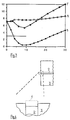
- Figure 2 which shows on a vertical axis the Coupling Loss in decibels, against Spacing Distance in micrometres on the horizontal axis.
- Curve A gives the 'butt' loss whilst Curve B is the loss associated with use of an ideal lens as a coupling device.
- Curve C shows the loss when an intermediate fibre coupling device is used and Curve D shows a loss when an axial well is used.
- Curve E illustrates the effect when a ring well coupling device is used. The Curves D and E for the well constructions have been drawn to ignore the 2:1 asymmetry effect but this makes very little difference to the final result. All the curves have been drawn with the approximate assumption that Gaussian fields are present.
- the graph also includes a horizontal line marking the position of a 3dB coupling loss.
- any lens used needs to be correctly aligned and this operation may be costly.
- the lens also needs to be of a high optical quality to avoid loss.
- the structure of the coupling device should additionally be small in size and capable of being assembled by automatic means. These conditions are difficult to fulfil but even when this is done correctly, the lens coupling device can still give losses of about 5dB.
- the present invention proposes an alternative way of reducing the mismatch by placing a blocking aperture of appropriate size in front of the fibre core.
- Figure 3 is a graph similar to that of Figure 2 which shows the result of using such a blocking aperture instead of a lens.
- Curve A gives the 'butt' loss whilst Curve B is the loss associated with an ideal lens.
- Curve F shows the loss associated with a blocking aperture. The loss in some cases is seen to be reduced by using the blocking aperture.
- the performance of the coupling device could be improved upon by correcting the phase every time it crosses ⁇ and starts to cancel, but this improvement would require the use of a circular symmetric phase plate which is centred on the fibre end.
- Figure 3 also includes a horizontal line marking the position of a 3dB coupling loss.
- Figure 4 in the upper part shows the end of an optical fibre with the core 2 surrounded by a body 3 of cladding material.
- the lower part of this Figure shows the core 2 end on a greatly enlarged scale and with the core longitudinal axis repositioned into a vertical attitude.
- the end surface of the core 2 has been cut away so that this lies below a plane defined by the surface of the cladding material at the fibre end.
- the result of having the core region depressed by a distance of a half of the wavelength of the laser light (that is, about 1.5 micrometres) is to introduce a relative delay in the light entering the core.
- the ring well construction can be expected to give a slightly better performance (Figure 2, Curve E) and this can be done by using a cladding material which has a readily etchable composition.
- the body 3 of cladding material is formed with an inner portion in contact with the core 2 the material of which inner portion is more readily etched than the outer cladding material.
- the region of this inner cladding material can thus be readily etched so that it will form a ring well 7 located about the core 2. It will be noted that use of a ring well cannot be expected to improve on a 3dB loss because the well acts as a diffractive zone plate that sends as much light 'out' as 'in', that is, it has as much a positive as a negative lens power.
- the ring well construction is modified by incorporating a blaze and thus a structure like a Fresnel lens/zone plate hybrid will be formed in accordance with the present invention.
- a construction is improved results and examples are seen in Figures 6 and 7.
- the ring well 7 is formed with a well floor of a non-planar shape so that a partial Fresnel lens construction has been formed.
- the end of the fibre core 2 material has also been recessed by the etching operation and given a curved shape on its outer surface.
- the Figure 6 and 7 embodiments could be readily fabricated by using special dopant profiles in the fibre manufacture. There is no necessary coincidence between the required zone plate dimensions and the size of the fibre core. It is not essential to use the specially fabricated fibres which have been mentioned because fibres can be made with differential etch rates independently from the arrangement of relative refractive indices.
- an optical fibre having a single core doped with germania and a cladding of pure silica was used.
- Sample fibre ends were etched in a solution of hydrofluoric acid buffered in ammonium fluoride in a ratio of 1:7. This gave a core end in the shape of a protruding stud of simple form and somewhat graded. The etch time required was dependent on etching temperature and the fibre composition.
- Etching trials with other etchants and fibres appeared to indicate that the use of boria (refractive index reducing) and phosphoria (refractive index increasing) doping, in conjunction with germania would allow a close and independent control of index and etched profile.
- the boria and phosphoria dopants are both generally etch rate increasing with high differential rates, although this factor depends upon the particular etchant which is used.
- Figures 8 to 11 show further profiles of core ends which have been shaped to provide the circular symmetric phase plate construction.
- Each of the Figures 8 to 11 represents the cross-section of the core region only.
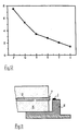
- These shapes can be considered in conjunction with the graph of Figure 12 which shows on the vertical axis the Coupling Loss in decibels against a profile type as denoted by the characters P to U on the horizontal axis.
- the Figure 12 curve was determined for a fibre having a core radius of 3.5 micrometres. Values for core radii having other dimensions would differ slightly but the overall trends would be expected to be similar.
- the selected shape of the core end contributes in some degree to the correction of the phase errors in the launch process it is relevant to coupling losses obtained with different core end profiles.
- the device comprises a mount 11 which supports an optical fibre having a fibre core 2 and body 3 of cladding material.
- the mount 11 additionally supports a laser 1 which is maintained at a predetermined distance from the fibre end and in a position where its light output can be fed directly into the end of the core 2.
- the end of the optical fibre carries the phase plate 7 structure of the invention.
- the construction of the coupling device of the invention as shown in figure 6 or 7 has been found to be simple to implement and fabrication can be effected by a mass production operation.
- the 'zone plate' feature is designed to be self-aligning on the fibre core and it offers low coupling losses.
- the spacing between the laser and the fibre end is normally about ten micrometres. However, the optimum spacing will be found to vary somewhat according to the particular shape required to be applied to the fibre core end.
- Figure 15 is a graph showing the reflection loss from a fibre end into a laser waveguide for various simple phase plate types.
- the vertical axis depicts the Reflection Loss in units of negative decibels against spacing distance on the horizontal axis.
- the graph thus shows the reflection loss for the path waveguide/fibre end/waveguide ignoring reflection effects at the waveguide end.
- curve A gives the 'butt' reflection for a plane fibre core end.
- Curve D shows a simple stud optimised for loss, whilst Curve E is for the ring well construction.
- Curve G shows the result with a simple stud optimised for low reflectivity.
- the graph shows the reflectivity of a plane glass surface (about -14dB).
- the Curve A indicates the performance of an untreated end, and it can be seen that the etched ends can be worse (higher reflectivity) as well as better.
Landscapes
- Physics & Mathematics (AREA)
- General Physics & Mathematics (AREA)
- Optics & Photonics (AREA)
- Optical Couplings Of Light Guides (AREA)
- Optical Fibers, Optical Fiber Cores, And Optical Fiber Bundles (AREA)
Description
- This invention relates to an optical fibre coupling device.
- In the coupling of laser light into a single-mode optical fibre it is important that losses in the transmitted light intensity should be kept low so that the total losses in a single-mode transmission system can be minimised. The launching of the light is usually effected from a single mode waveguide device such as a laser or amplifier and, whilst a perfect launching arrangement is theoretically possible, practical constraints usually limit the coupling efficiency to only about fifty percent, that is with a loss of more than three decibels (dB). Many real systems in practice will show losses as high as 5dB.
- Attempts have been made to improve the coupling efficiency by using lensing schemes which are intended to match the typically small and elliptically-shaped laser mode to a larger spot area requirement and a circular fibre mode. Thus, chemically etched conical microlenses have been disclosed in a paper by G. Eisenstein and D. Vitello in Applied Optics, Vol. 21, No. 19, 1 October 1982, pp 3470 to 3474. However, these lens devices can still give high losses and the conical external shape may represent an unwanted feature. Losses are mainly due to the effect of a partial cancellation between different parts of the launch wave due to the existence of a phase mismatch in the wave. A further example is found in EP-A- 61378.
- This source of losses is capable of being corrected and the present invention was devised as a way of making this correction which enables certain difficulties in implementation to be avoided.
- According to the invention there is provided an optical coupling device comprising an optical fibre waveguide having a core and a cladding, in which at a fibre end face an axially extended ring well is recessed in said cladding around said core and, in which said ring well is formed with a well floor of a non-planar shape so as to define a partial Fresnel lens construction.
- The invention will now be described with reference to the accompanying drawings, in which:-
- Figure 1 is a sketch of a simple butt coupling arrangement of the prior art showing a waveguide device and an optical fibre on a greatly enlarged scale;
- Figure 2 is a graph depicting the transmission losses that can be expected with a variation in separation distance between the waveguide and the fibre core end;
- Figure 3 is a further graph depicting the effect of placing a blocking aperture of appropriate size in front of the fibre core end;
- Figure 4 is a sketch of one form of coupling device;
- Figures 5 shows a coupling device;
- Figures 6 and 7 show embodiments of the present invention;
- Figures 8 to 11 show profiles of core ends;
- Figure 12 is a graph showing the transmission losses for various shapes of the core material end;
- Figure 13 is a sketch of a complete optical fibre coupling device;
- Figure 14 shows some possible paths for light beams travelling through the fibre core end face; and,
- Figure 15 is a graph showing the reflection loss from a fibre end into a laser waveguide for various simple phase plate types.
- As shown in Figure 1, an optical fibre coupling arrangement is formed when a waveguide device which is a laser 1 is directed towards an end of an optical fibre having a
fibre core 2 which is surrounded by abody 3 of cladding material. Light from the laser 1 in adivergent beam 4 thus strikes the end of thefibre core 2, and a particular proportion of the laser 1 light output will thus be directed into thecore 2 and along the optical fibre. The shape of the wave front entering the fibre is indicated by thecurve 5. - This is a simple butt coupling arrangement and it will be apparent that the resulting coupling loss will be at a minimum value when the spacing distance between the laser 1 and
core 2 is zero. - Figure 2 which shows on a vertical axis the Coupling Loss in decibels, against Spacing Distance in micrometres on the horizontal axis.
- The values for the graph were calculated for a representative case of launch from a 1.5 x 3 micrometre spot waveguide launching into a nine micrometre spot size fibre, for a 1.5 micrometre wavelength of the light. Curve A gives the 'butt' loss whilst Curve B is the loss associated with use of an ideal lens as a coupling device. Curve C shows the loss when an intermediate fibre coupling device is used and Curve D shows a loss when an axial well is used. Curve E illustrates the effect when a ring well coupling device is used. The Curves D and E for the well constructions have been drawn to ignore the 2:1 asymmetry effect but this makes very little difference to the final result. All the curves have been drawn with the approximate assumption that Gaussian fields are present.
- The graph also includes a horizontal line marking the position of a 3dB coupling loss.
- It might be reasonably assumed from this data that the use of a lens or lenses is an obvious solution to the coupling device probe. However, any lens used needs to be correctly aligned and this operation may be costly. The lens also needs to be of a high optical quality to avoid loss. The structure of the coupling device should additionally be small in size and capable of being assembled by automatic means. These conditions are difficult to fulfil but even when this is done correctly, the lens coupling device can still give losses of about 5dB.
- These losses are essentially due to the effect of a partial cancellation which can occur between different parts of the launch wave due to phase mismatch as already explained. Instead of using a lens, the present invention proposes an alternative way of reducing the mismatch by placing a blocking aperture of appropriate size in front of the fibre core.
- Figure 3 is a graph similar to that of Figure 2 which shows the result of using such a blocking aperture instead of a lens. As before, Curve A gives the 'butt' loss whilst Curve B is the loss associated with an ideal lens. Curve F shows the loss associated with a blocking aperture. The loss in some cases is seen to be reduced by using the blocking aperture. The performance of the coupling device could be improved upon by correcting the phase every time it crosses π and starts to cancel, but this improvement would require the use of a circular symmetric phase plate which is centred on the fibre end. Figure 3 also includes a horizontal line marking the position of a 3dB coupling loss.
- Figure 4 in the upper part shows the end of an optical fibre with the
core 2 surrounded by abody 3 of cladding material. The lower part of this Figure shows thecore 2 end on a greatly enlarged scale and with the core longitudinal axis repositioned into a vertical attitude. By making use of a differential etch process, the end surface of thecore 2 has been cut away so that this lies below a plane defined by the surface of the cladding material at the fibre end. The result of having the core region depressed by a distance of a half of the wavelength of the laser light (that is, about 1.5 micrometres) is to introduce a relative delay in the light entering the core. A similar delay would be introduced if the etching effect acted only on the cladding material of the fibre so that the core region will become raised by a distance of a half wavelength (as shown by the dotted line 6) above the plane of the cladding material end. - This practical construction where the end of the core material is displaced relative to that of the cladding material can be termed an 'axial well". It might be throught that this construction is no more than an approximation to the shape of an optical lens but in fact the coupling effect is almost the same whether the core material is raised above or depressed below the plane of the cladding material end.
- The performance of this axial well is shown by the Curve D in Figure 2.
- The ring well construction can be expected to give a slightly better performance (Figure 2, Curve E) and this can be done by using a cladding material which has a readily etchable composition.
- In Figure 5, the
body 3 of cladding material is formed with an inner portion in contact with thecore 2 the material of which inner portion is more readily etched than the outer cladding material. The region of this inner cladding material can thus be readily etched so that it will form a ring well 7 located about thecore 2. It will be noted that use of a ring well cannot be expected to improve on a 3dB loss because the well acts as a diffractive zone plate that sends as much light 'out' as 'in', that is, it has as much a positive as a negative lens power. - The ring well construction is modified by incorporating a blaze and thus a structure like a Fresnel lens/zone plate hybrid will be formed in accordance with the present invention. Such a construction is improved results and examples are seen in Figures 6 and 7.
- It will be seen in Figures 6 and 7 that the ring well 7 is formed with a well floor of a non-planar shape so that a partial Fresnel lens construction has been formed. In Figure 7, the end of the
fibre core 2 material has also been recessed by the etching operation and given a curved shape on its outer surface. - The Figure 6 and 7 embodiments could be readily fabricated by using special dopant profiles in the fibre manufacture. There is no necessary coincidence between the required zone plate dimensions and the size of the fibre core. It is not essential to use the specially fabricated fibres which have been mentioned because fibres can be made with differential etch rates independently from the arrangement of relative refractive indices.
- In one series of experiments, an optical fibre having a single core doped with germania and a cladding of pure silica was used.
Sample fibre ends were etched in a solution of hydrofluoric acid buffered in ammonium fluoride in a ratio of 1:7. This gave a core end in the shape of a protruding stud of simple form and somewhat graded. The etch time required was dependent on etching temperature and the fibre composition. - When using a 'Corning' (trade mark) single mode fibre end the etch time with the abovementioned solution was fifteen minutes at a temperature of 50°C. Under test, the minimum loss obtainable with this fibre end was found to be 2.7dB.
- In further experiments, a similar fibre end was etched in a solution of 55 millilitres nitric acid, 55 millilitres acetic acid, 25 millilitres hydrofluoric acid (40% in water) and 0.16 grams of iodine. This solution produced a graded profile.
- Whichever etching solution had been used, the grading effect was found to be produced by a combination of differential etch rates with a relevant graded composition of the fibre. A particular etching process was found to have its own smoothing characteristics.
- Etching trials with other etchants and fibres appeared to indicate that the use of boria (refractive index reducing) and phosphoria (refractive index increasing) doping, in conjunction with germania would allow a close and independent control of index and etched profile. The boria and phosphoria dopants are both generally etch rate increasing with high differential rates, although this factor depends upon the particular etchant which is used.
- Figures 8 to 11 show further profiles of core ends which have been shaped to provide the circular symmetric phase plate construction. Each of the Figures 8 to 11 represents the cross-section of the core region only. These shapes can be considered in conjunction with the graph of Figure 12 which shows on the vertical axis the Coupling Loss in decibels against a profile type as denoted by the characters P to U on the horizontal axis. The Figure 12 curve was determined for a fibre having a core radius of 3.5 micrometres. Values for core radii having other dimensions would differ slightly but the overall trends would be expected to be similar.
- Since the selected shape of the core end contributes in some degree to the correction of the phase errors in the launch process it is relevant to coupling losses obtained with different core end profiles.
- In Figure 12, the values for Coupling Loss were obtained by calculation and, as a start, the profile type P is that for a simple butt coupling where the fibre core has an unformed shape. An improvement of almost three dB is effected by using a blocking aperture, profile type Q. A further reduction in loss is made when the core end is given the simple hat shape of Figure 10, and this construction corresponds to profile type R.
- An additional improvement is seen when the core end has a double well shaping as depicted in Figure 11, this corresponds to the profile type S. A simple lens shaping as shown in Figure 8 gives the coupling loss of profile type T. A lens/well shaping as shown in Figure 9 gives the coupling loss of profile type U.
- A complete construction of an optical fibre coupling device is shown in Figure 13. The device comprises a mount 11 which supports an optical fibre having a
fibre core 2 andbody 3 of cladding material. The mount 11 additionally supports a laser 1 which is maintained at a predetermined distance from the fibre end and in a position where its light output can be fed directly into the end of thecore 2. The end of the optical fibre carries the phase plate 7 structure of the invention. - The construction of the coupling device of the invention as shown in figure 6 or 7 has been found to be simple to implement and fabrication can be effected by a mass production operation. The 'zone plate' feature is designed to be self-aligning on the fibre core and it offers low coupling losses.
- The same technique as that proposed to enhance the coupling efficiency can also be used to reduce the reflectivity of the fibre end face as seen by the laser/waveguide. There is no absolute reduction in reflectivity, but the cancellation effect can result in less light being coupled back into the waveguide. This effect could also reduce the reflection back into the fibre from the end. The effect on reflectivity arises because the physical shape of the phase plate also affects the differential phase of light in (in the case of the simple hat/stud profile) the cladding and core regions. This effect is different from the transmission effect because the two paths are different. Some of the possible light paths are shown in Figure 14. These are:-
- Transmission through the elevated glass stud, and through the air around it (Figure 14,
light paths 12 and 13), differing because of the glass refractive index. - Reflection twice through the air around the stud. (Figure 14,
light paths 16 and 17), different for geometrical reasons; internal reflection (from below) would be different because of the glass refractive index. - Clearly, it will in general be true that the best shape for a reflection reduction will be different from that for transmission maximisation. For the most part the optimisation involved is on the height of the stud. It happens fortuitously that one can get both conditions near to optimum with a single shape for typical fibre.
- The foregoing descriptions of embodiments of the invention have been given by way of example only and a number of modifications may be made without departing from the scope of the invention as defined in the appended claims. For example, the spacing between the laser and the fibre end is normally about ten micrometres. However, the optimum spacing will be found to vary somewhat according to the particular shape required to be applied to the fibre core end.
- Figure 15 is a graph showing the reflection loss from a fibre end into a laser waveguide for various simple phase plate types. The vertical axis depicts the Reflection Loss in units of negative decibels against spacing distance on the horizontal axis. The graph thus shows the reflection loss for the path waveguide/fibre end/waveguide ignoring reflection effects at the waveguide end.
- The symbols for the reflection curves correspond to those given in Figure 2. Thus curve A gives the 'butt' reflection for a plane fibre core end. Curve D shows a simple stud optimised for loss, whilst Curve E is for the ring well construction. The Curve G shows the result with a simple stud optimised for low reflectivity.
- The graph shows the reflectivity of a plane glass surface (about -14dB).
- The Curve A indicates the performance of an untreated end, and it can be seen that the etched ends can be worse (higher reflectivity) as well as better.
Claims (1)
- An optical fibre coupling device comprising an optical fibre waveguide having a core (2) and a cladding (3), in which at a fibre end face an axially extended ring well (7) is recessed in said cladding (3) around said core (2), characterized in that said ring well (7) is formed with a well floor of a non-planar shape so as to define a partial Fresnel lens construction.
Applications Claiming Priority (2)
| Application Number | Priority Date | Filing Date | Title |
|---|---|---|---|
| GB9007320A GB2242755B (en) | 1990-03-31 | 1990-03-31 | Optical fibre coupling device |
| GB9007320 | 1990-03-31 |
Publications (2)
| Publication Number | Publication Date |
|---|---|
| EP0455334A1 EP0455334A1 (en) | 1991-11-06 |
| EP0455334B1 true EP0455334B1 (en) | 1995-03-01 |
Family
ID=10673676
Family Applications (1)
| Application Number | Title | Priority Date | Filing Date |
|---|---|---|---|
| EP91302250A Expired - Lifetime EP0455334B1 (en) | 1990-03-31 | 1991-03-15 | Opticle fibre coupling device with a phase plate |
Country Status (5)
| Country | Link |
|---|---|
| US (1) | US5132079A (en) |
| EP (1) | EP0455334B1 (en) |
| JP (1) | JP3364721B2 (en) |
| DE (1) | DE69107668T2 (en) |
| GB (1) | GB2242755B (en) |
Families Citing this family (21)
| Publication number | Priority date | Publication date | Assignee | Title |
|---|---|---|---|---|
| US5459803A (en) * | 1993-02-18 | 1995-10-17 | The Furukawa Electric Co., Ltd. | Quartz-based optical fiber with a lens and its manufacturing method |
| US5687264A (en) * | 1995-08-24 | 1997-11-11 | Sandia Corporation | Apparatus for injecting high power laser light into a fiber optic cable |
| AU7844498A (en) | 1996-12-09 | 1998-07-03 | Tjin, Swee Chuan | Method and apparatus for continuous cardiac output monitoring |
| AUPR262601A0 (en) | 2001-01-19 | 2001-02-15 | University Of Melbourne, The | Optical fibre lens and method of forming same |
| JP2002277657A (en) * | 2001-03-19 | 2002-09-25 | Nec Corp | Integrated optical module |
| US6948862B2 (en) * | 2002-02-22 | 2005-09-27 | Brown Joe D | Apparatus and method for coupling laser energy into small core fibers |
| US7090411B2 (en) * | 2002-02-22 | 2006-08-15 | Brown Joe D | Apparatus and method for diffusing laser energy that fails to couple into small core fibers, and for reducing coupling to the cladding of the fiber |
| US8463080B1 (en) | 2004-01-22 | 2013-06-11 | Vescent Photonics, Inc. | Liquid crystal waveguide having two or more control voltages for controlling polarized light |
| US8989523B2 (en) | 2004-01-22 | 2015-03-24 | Vescent Photonics, Inc. | Liquid crystal waveguide for dynamically controlling polarized light |
| US8860897B1 (en) | 2004-01-22 | 2014-10-14 | Vescent Photonics, Inc. | Liquid crystal waveguide having electric field orientated for controlling light |
| US20050271325A1 (en) * | 2004-01-22 | 2005-12-08 | Anderson Michael H | Liquid crystal waveguide having refractive shapes for dynamically controlling light |
| EP1635204A1 (en) * | 2004-09-10 | 2006-03-15 | Schott AG | Glass fibre with integrated diffractive element on the top of its end face |
| US20070292087A1 (en) * | 2006-06-19 | 2007-12-20 | Joe Denton Brown | Apparatus and method for diffusing laser energy that fails to couple into small core fibers, and for reducing coupling to the cladding of the fiber |
| US7540668B2 (en) * | 2006-12-22 | 2009-06-02 | Brown Joe D | Fiber optic connector for coupling laser energy into small core fibers, and termination method therefor |
| US20090177191A1 (en) * | 2007-12-11 | 2009-07-09 | Brown Joe D | Laser surgery methods and apparatus |
| WO2010053575A2 (en) * | 2008-11-07 | 2010-05-14 | Joe Denton Brown | Apparatus and method for detecting overheating during laser surgery |
| US9366938B1 (en) * | 2009-02-17 | 2016-06-14 | Vescent Photonics, Inc. | Electro-optic beam deflector device |
| US9314303B2 (en) * | 2010-03-23 | 2016-04-19 | Joe Denton Brown | Laser surgery controller with variable time delay and feedback detector sensitivity control |
| US8638428B2 (en) | 2010-06-01 | 2014-01-28 | Joe Denton Brown | Method and apparatus for using optical feedback to detect fiber breakdown during surgical laser procedures |
| US8995038B1 (en) | 2010-07-06 | 2015-03-31 | Vescent Photonics, Inc. | Optical time delay control device |
| US9766420B2 (en) | 2013-03-15 | 2017-09-19 | Joe Denton Brown | Apparatus and method for absorbing laser energy that fails to couple into the core of a laser fiber, and for absorbing the energy that has been transmitted to the cladding of the laser |
Family Cites Families (17)
| Publication number | Priority date | Publication date | Assignee | Title |
|---|---|---|---|---|
| NL7706379A (en) * | 1977-06-10 | 1978-12-12 | Philips Nv | METHOD FOR THE MANUFACTURE OF A COUPLING ELEMENT. |
| US4148554A (en) * | 1977-08-05 | 1979-04-10 | Minnesota Mining And Manufacturing Company | Method of providing recessed optical fiber ends for use in connector structures |
| DE2912563A1 (en) * | 1979-03-29 | 1980-10-09 | Licentia Gmbh | METHOD FOR GLASS EQUIPMENT |
| FR2502345B1 (en) * | 1981-03-17 | 1985-01-04 | Thomson Csf | |
| US4676586A (en) * | 1982-12-20 | 1987-06-30 | General Electric Company | Apparatus and method for performing laser material processing through a fiber optic |
| JPS6043889A (en) * | 1983-08-22 | 1985-03-08 | Hitachi Ltd | Light-emitting device |
| SE455968B (en) * | 1985-03-01 | 1988-08-22 | Ericsson Telefon Ab L M | Optical cable |
| DE3632743A1 (en) * | 1986-09-26 | 1988-03-31 | Standard Elektrik Lorenz Ag | Optical waveguide with a microlens at the end |
| AU596451B2 (en) * | 1986-10-31 | 1990-05-03 | Alcatel N.V. | Optical communication system |
| US4763976A (en) * | 1987-05-21 | 1988-08-16 | Corning Glass Works | Connector employing mode field modification |
| US4799755A (en) * | 1987-12-21 | 1989-01-24 | General Electric Company | Laser materials processing with a lensless fiber optic output coupler |
| US4966433A (en) * | 1988-03-03 | 1990-10-30 | At&T Bell Laboratories | Device including a component in alignment with a substrate-supported waveguide |
| US4919506A (en) * | 1989-02-24 | 1990-04-24 | General Electric Company | Single mode optical fiber coupler |
| US5046809A (en) * | 1989-09-29 | 1991-09-10 | Siemens Aktiengesellschaft | Coupling arrangement for optically coupling a fiber to a planar optical waveguide integrated on a substrate |
| US5011254A (en) * | 1989-11-30 | 1991-04-30 | At&T Bell Laboratories | Coupling of optical devices to optical fibers by means of microlenses |
| US5044717A (en) * | 1990-01-18 | 1991-09-03 | Acculase, Inc. | Method and apparatus for coupling high energy laser to fiberoptic waveguide |
| US5018820A (en) * | 1990-03-02 | 1991-05-28 | Gte Laboratories Incorporated | Method of optically coupling an uptapered single-mode optical fiber to optoelectronic components |
-
1990
- 1990-03-31 GB GB9007320A patent/GB2242755B/en not_active Expired - Fee Related
-
1991
- 1991-03-15 EP EP91302250A patent/EP0455334B1/en not_active Expired - Lifetime
- 1991-03-15 DE DE69107668T patent/DE69107668T2/en not_active Expired - Fee Related
- 1991-03-25 US US07/675,079 patent/US5132079A/en not_active Expired - Lifetime
- 1991-03-28 JP JP08726691A patent/JP3364721B2/en not_active Expired - Fee Related
Also Published As
| Publication number | Publication date |
|---|---|
| JP3364721B2 (en) | 2003-01-08 |
| GB2242755A (en) | 1991-10-09 |
| GB2242755B (en) | 1994-07-27 |
| DE69107668D1 (en) | 1995-04-06 |
| US5132079A (en) | 1992-07-21 |
| EP0455334A1 (en) | 1991-11-06 |
| GB9007320D0 (en) | 1990-05-30 |
| DE69107668T2 (en) | 1995-06-29 |
| JPH0777631A (en) | 1995-03-20 |
Similar Documents
| Publication | Publication Date | Title |
|---|---|---|
| US5132079A (en) | Optical fibre coupling device | |
| US4265699A (en) | Etching of optical fibers | |
| US4490020A (en) | Coupling system for output light of semiconductor laser | |
| US4456330A (en) | Optical coupling system and method for manufacturing same | |
| US6411762B1 (en) | Optical fiber with irregularities at cladding boundary | |
| US6963682B2 (en) | Beam altering fiber lens device and method of manufacture | |
| US5566267A (en) | Flat surfaced optical fibers and diode laser medical delivery devices | |
| US4919506A (en) | Single mode optical fiber coupler | |
| EP0872747B1 (en) | Optical module | |
| US7068882B2 (en) | Optical fiber microlens, optical fiber and method of positioning optical fiber | |
| US6130972A (en) | Lensed optical fiber and laser module | |
| JP2006512616A (en) | Optical fiber lens and manufacturing method | |
| EP0683410B1 (en) | Optical fiber light coupling interface with an enlarged incident surface | |
| GB2354839A (en) | Hyperbolic transfer lens for fibre optics | |
| EP3441805B1 (en) | Lens-attached optical fiber and optical coupler | |
| US4611883A (en) | Two-dimensional optics element for correcting aberrations | |
| US6956876B1 (en) | Method and apparatus for coupling a multimode laser to a multimode fiber | |
| US20030165290A1 (en) | Optical signal altering lensed apparatus and method of manufacture | |
| JPH05114767A (en) | Method for manufacturing optical coupling device | |
| JPH05281443A (en) | Optical coupling method | |
| US6661582B1 (en) | Optical transmitter and anamorphic lens therefor | |
| JPH0544643B2 (en) | ||
| JP2017026660A (en) | Optical fiber terminal | |
| JPH0784146A (en) | Optical element for connection, method of manufacturing the same, and method of connecting optical element | |
| JP3821576B2 (en) | Optical module |
Legal Events
| Date | Code | Title | Description |
|---|---|---|---|
| PUAI | Public reference made under article 153(3) epc to a published international application that has entered the european phase |
Free format text: ORIGINAL CODE: 0009012 |
|
| AK | Designated contracting states |
Kind code of ref document: A1 Designated state(s): DE FR NL SE |
|
| 17P | Request for examination filed |
Effective date: 19920406 |
|
| 17Q | First examination report despatched |
Effective date: 19930826 |
|
| GRAA | (expected) grant |
Free format text: ORIGINAL CODE: 0009210 |
|
| AK | Designated contracting states |
Kind code of ref document: B1 Designated state(s): DE FR NL SE |
|
| PG25 | Lapsed in a contracting state [announced via postgrant information from national office to epo] |
Ref country code: NL Free format text: LAPSE BECAUSE OF NON-PAYMENT OF DUE FEES Effective date: 19950301 |
|
| ET | Fr: translation filed | ||
| REF | Corresponds to: |
Ref document number: 69107668 Country of ref document: DE Date of ref document: 19950406 |
|
| PG25 | Lapsed in a contracting state [announced via postgrant information from national office to epo] |
Ref country code: SE Effective date: 19950601 |
|
| NLV1 | Nl: lapsed or annulled due to failure to fulfill the requirements of art. 29p and 29m of the patents act | ||
| PLBE | No opposition filed within time limit |
Free format text: ORIGINAL CODE: 0009261 |
|
| STAA | Information on the status of an ep patent application or granted ep patent |
Free format text: STATUS: NO OPPOSITION FILED WITHIN TIME LIMIT |
|
| PGFP | Annual fee paid to national office [announced via postgrant information from national office to epo] |
Ref country code: FR Payment date: 19960130 Year of fee payment: 6 |
|
| 26N | No opposition filed | ||
| PGFP | Annual fee paid to national office [announced via postgrant information from national office to epo] |
Ref country code: DE Payment date: 19960525 Year of fee payment: 6 |
|
| PG25 | Lapsed in a contracting state [announced via postgrant information from national office to epo] |
Ref country code: FR Free format text: LAPSE BECAUSE OF NON-PAYMENT OF DUE FEES Effective date: 19971128 |
|
| PG25 | Lapsed in a contracting state [announced via postgrant information from national office to epo] |
Ref country code: DE Effective date: 19971202 |
|
| REG | Reference to a national code |
Ref country code: FR Ref legal event code: ST |